

Page 1

CNC SYSTEM
OSP-P200M
OSP-P20M
SPECIAL FUNCTION FOR MB-V/MD-V/MU-V SERIES
INSTRUCTION MANUAL
(2nd Edition)
Pub No. 5309-E-R1 (ME61-048-R2) Feb. 2007
Page 2

5309-E P-(i)
SAFETY PRECAUTIONS
SAFETY PRECAUTIONS
The machine is equipped with safety devices which serve to protect personnel and the machine itself from
hazards arising from unforeseen accidents. However, operators must not rely exclusively on these safety
devices: they must also become fully familiar with the safety guidelines presented below to ensure accidentfree operation.
This instruction manual and the warning signs attached to the machine cover only those hazards which
Okuma can predict. Be aware that they do not cover all possible hazards.
1. Precautions Relating to Installation
(1) Please be noted about a primary power supply as follows.
• Do not draw the primary power supply from a distribution panel that also supplies a major
noise source (for example, an electric welder or electric discharge machine) since this
could cause malfunction of the CNC unit.
• If possible, connect the machine to a ground not used by any other equipment. If there is
no choice but to use a common ground, the other equipment must not generate a large
amount of noise (such as an electric welder or electric discharge machine).
(2) Installation Environment
Observe the following points when installing the control enclosure.
• Make sure that the CNC unit will not be subject to direct sunlight.
• Make sure that the control enclosure will not be splashed with chips, water, or oil.
• Make sure that the control enclosure and operation panel are not subject to excessive
vibrations or shock.
• The permissible ambient temperature range for the control enclosure is 5 to 40°C.
• The permissible ambient humidity range for the control enclosure is relative humidity 50%
or less at 40°C (no condensation).
• The maximum altitude at which the control enclosure can be used is 1000 m (3281ft.).
2. Points to Check before Turning on the Power
(1) Close all the doors of the control enclosure and operation panel to prevent the entry of water,
chips, and dust.
(2) Make absolutely sure that there is nobody near the moving parts of the machine, and that there
are no obstacles around the machine, before starting machine operation.
(3) When turning on the power, turn on the main power disconnect switch first, then the CONTROL
ON switch on the operation panel.
Page 3

3. Precautions Relating to Operation
(1) After turning on the power, carry out inspection and adjustment in accordance with the daily
inspection procedure described in this instruction manual.
(2) Use tools whose dimensions and type are appropriate for the work undertaken and the machine
specifications. Do not use badly worn tools since they can cause accidents.
(3) Do not, for any reason, touch the spindle or tool while spindle indexing is in progress since the
spindle could rotate: this is dangerous.
(4) Check that the workpiece and tool are properly secured.
(5) Never touch a workpiece or tool while it is rotating: this is extremely dangerous.
(6) Do not remove chips by hand while machining is in progress since this is dangerous. Always
stop the machine first, then remove the chips with a brush or broom.
(7) Do not operate the machine with any of the safety devices removed. Do not operate the
machine with any of the covers removed unless it is necessary to do so.
(8) Always stop the machine before mounting or removing a tool.
5309-E P-(ii)
SAFETY PRECAUTIONS
(9) Do not approach or touch any moving part of the machine while it is operating.
(10) Do not touch any switch or button with wet hands. This is extremely dangerous.
(11) Before using any switch or button on the operation panel, check that it is the one intended.
4. Precautions Relating to the ATC
(1) The tool clamps of the magazine, spindle, etc., are designed for reliability, but it is possible that
a tool could be released and fall in the event of an unforeseen accident, exposing you to
danger: do not touch or approach the ATC mechanism during ATC operation.
(2) Always inspect and change tools in the magazine in the manual magazine interrupt mode.
(3) Remove chips adhering to the magazine at appropriate intervals since they can cause
misoperation. Do not use compressed air to remove these chips since it will only push the chips
further in.
(4) If the ATC stops during operation for some reason and it has to be inspected without turning the
power off, do not touch the ATC since it may start moving suddenly.
5. On Finishing Work
(1) On finishing work, clean the vicinity of the machine.
(2) Return the ATC, APC and other equipment to the predetermined retraction position.
(3) Always turn off the power to the machine before leaving it.
(4) To turn off the power, turn off the CONTROL ON switch on the operation panel first, then the
main power disconnect switch.
Page 4

5309-E P-(iii)
SAFETY PRECAUTIONS
6. Precautions during Maintenance Inspection and When Trouble Occurs
In order to prevent unforeseen accidents, damage to the machine, etc., it is essential to observe the
following points when performing maintenance inspections or during checking when trouble has
occurred.
(1) When trouble occurs, press the emergency stop button on the operation panel to stop the
machine.
(2) Consult the person responsible for maintenance to determine what corrective measures need
to be taken.
(3) If two or more persons must work together, establish signals so that they can communicate to
confirm safety before proceeding to each new step.
(4) Use only the specified replacement parts and fuses.
(5) Always turn the power off before starting inspection or changing parts.
(6) When parts are removed during inspection or repair work, always replace them as they were
and secure them properly with their screws, etc.
(7) When carrying out inspections in which measuring instruments are used - for example voltage
checks - make sure the instrument is properly calibrated.
(8) Do not keep combustible materials or metals inside the control enclosure or terminal box.
(9) Check that cables and wires are free of damage: damaged cables and wires will cause current
leakage and electric shocks.
(10) Maintenance inside the Control Enclosure
a. Switch the main power disconnect switch OFF before opening the control enclosure door.
b. Even when the main power disconnect switch is OFF, there may some residual charge in
the MCS drive unit (servo/spindle), and for this reason only service personnel are permitted
to perform any work on this unit. Even then, they must observe the following precautions.
• MCS drive unit (servo/spindle)
The residual voltage discharges two minutes after the main switch is turned OFF.
c. The control enclosure contains the NC unit, and the NC unit has a printed circuit board
whose memory stores the machining programs, parameters, etc. In order to ensure that the
contents of this memory will be retained even when the power is switched off, the memory
is supplied with power by a battery. Depending on how the printed circuit boards are
handled, the contents of the memory may be destroyed and for this reason only service
personnel should handle these boards.
Page 5

(11) Periodic Inspection of the Control Enclosure
a. Cleaning the cooling unit
The cooling unit in the door of the control enclosure serves to prevent excessive
temperature rise inside the control enclosure and increase the reliability of the NC unit.
Inspect the following points every three months.
• Is the fan motor inside the cooling unit working?
The motor is normal if there is a strong draft from the unit.
• Is the external air inlet blocked?
If it is blocked, clean it with compressed air.
7. General Precautions
(1) Keep the vicinity of the machine clean and tidy.
(2) Wear appropriate clothing while working, and follow the instructions of someone with sufficient
training.
(3) Make sure that your clothes and hair cannot become entangled in the machine. Machine
operators must wear safety equipment such as safety shoes and goggles.
5309-E P-(iv)
SAFETY PRECAUTIONS
(4) Machine operators must read the instruction manual carefully and make sure of the correct
procedure before operating the machine.
(5) Memorize the position of the emergency stop button so that you can press it immediately at any
time and from any position.
(6) Do not access the inside of the control panel, transformer, motor, etc., since they contain high-
voltage terminals and other components which are extremely dangerous.
(7) If two or more persons must work together, establish signals so that they can communicate to
confirm safety before proceeding to each new step.
Page 6

8. Symbols Used in This Manual
The following warning indications are used in this manual to draw attention to information of
particular importance. Read the instructions marked with these symbols carefully and follow them.
DANGER
indicates an imminently hazardous situation which, if not avoided, will result in death or serious
injury.
WARNING
indicates a potentially hazardous situation which, if not avoided, could result in death or serious injury.
CAUTION
indicates a potentially hazardous situation which, if not avoided, may result in minor or moderate injury.
CAUTION
5309-E P-(v)
SAFETY PRECAUTIONS
indicates a potentially hazardous situation which, if not avoided, may result in damage to your
property.
SAFETY INSTRUCTIONS
indicates general instructions for safe operation.
Page 7

5309-E P-(i)
INTRODUCTION
INTRODUCTION
Thank you very much for choosing our CNC system. This numerical control system is an expandable CNC
with various features. Major features of the CNC system are described below.
(1) NC operation panels
The following types of NC operation panels are offered to improve the user-friendliness.
• Color CRT operation panels
• Thin color operation panels (horizontal)
• Thin color operation panels (vertical)
One or more of the above types may not be used for some models.
(2) Machining management functions
These functions contribute to the efficient operation of the CNC system and improve the profitability from
small quantity production of multiple items and variable quantity production of variations. Major control
functions are described below.
a. Reduction of setup time
With increase in small-volume production, machining data setting is more frequently needed. The
simplified file operation facilitates such troublesome operation. The documents necessary for setup,
such as work instructions, are displayed on the CNC system to eliminate the necessity of controlling
drawings and further reduce the setup time.
b. Production Status Monitor
The progress and operation status can be checked on a real-time basis on the screen of the CNC
system.
c. Reduction of troubleshooting time
Correct information is quickly available for troubleshooting.
(3) Help functions
When an alarm is raised, press the help key to view the content of the alarm.
This helps take quick action against the alarm.
To operate the CNC system to its maximum performance, thoroughly read and understand this instruction
manual before use.
Keep this instruction manual at hand so that it will be available when you need a help.
Screens
Different screens are used for different models. Therefore, the
screens used on your CNC system may differ from those shown
in this manual.
Page 8

CONTENTS
SECTION 1 ROBOT/LOADER INTERFACE TYPES
SECTION 2 Chuck (Jig) Control
SECTION 3 Work Sit Confirmation
SECTION 4 OPERATION DOOR AUTO OPEN/CLOSE SPEC
SECTION 5 STACKER CRANE INTERFACE
SECTION 6 DNC-C STACKER CRANE I/F FOR ETHERNET
5309-E P-(i)
CONTENTS
SECTION 7 SEMI-DRY COOLANT UNIT
This instruction manual consists of several specifications for peripheral devices
and systems including those not selected by some users.
For details of each specification, refer to the corresponding materials such as the
final specification.
Page 9

5309-E P-(i)
TABLE OF CONTENTS
TABLE OF CONTENTS
SECTION 1 ROBOT/LOADER INTERFACE TYPES...................................................1
1. Robot/loader Interface Types ..................................................................................................1
2. Automatic Mode....................................................................................................................... 1
3. NC Operation Interlock ............................................................................................................ 1
4. List of Input and Output Signals............................................................................................... 3
4-1. Inputs from the Robot/loader to the NC ............................................................................ 3
4-2. Outputs from the NC to the Robot/loader ......................................................................... 4
5. Description of Signals.............................................................................................................. 5
5-1. Robot/loader Interface Type B.......................................................................................... 5
5-2. Robot/loader Interface Type C ....................................................................................... 12
6. Interlock ................................................................................................................................. 20
6-1. Axis Interlock .................................................................................................................. 20
6-2. APC Interlock.................................................................................................................. 20
7. Work Condition Display Function........................................................................................... 21
8. Parameters ............................................................................................................................ 22
9. Automatic Power Shutdown................................................................................................... 23
9-1. Effective Conditions........................................................................................................23
9-2. Description of the Function............................................................................................. 24
9-3. Parameters ..................................................................................................................... 25
10.Input/Output Bit ...................................................................................................................... 26
SECTION 2 CHUCK (JIG) CONTROL.......................................................................30
1. No. 1 Chuck (Jig)................................................................................................................... 30
1-1. Clamping Modes............................................................................................................. 30
1-2. Chuck clamp/unclamp commands.................................................................................. 30
1-3. Chuck clamp/unclamp sequences.................................................................................. 33
1-4. "Chuck Open/Closed" limit switches............................................................................... 34
1-5. Work clamp/unclamp timers ........................................................................................... 35
1-6. Timing chart.................................................................................................................... 36
1-7. Interlocking ..................................................................................................................... 37
1-8. Special conditions........................................................................................................... 38
1-9. Status indicators ............................................................................................................. 38
2. Chuck (jig) pressure switching............................................................................................... 39
2-1. No. 1 chuck (jig).............................................................................................................. 39
3. Chuck air blow control ........................................................................................................... 45
3-1. Chuck air blow commands ............................................................................................. 45
3-2. Special cases ................................................................................................................. 45
4. Input/output signals................................................................................................................ 46
Page 10

5309-E P-(ii)
TABLE OF CONTENTS
SECTION 3 WORK SIT CONFIRMATION.................................................................47
1. Work Sit Condition Monitor....................................................................................................47
1-1. M Codes ......................................................................................................................... 47
1-2. Entering the sit condition monitoring mode .................................................................... 47
1-3. Continuous monitoring in work sit condition monitoring mode ....................................... 48
1-4. Exiting the sit condition monitoring mode ....................................................................... 49
1-5. Linking the seating air blow ............................................................................................ 50
1-6. Protection against air outlet clogging matter .................................................................. 50
1-7. Sit condition confirmation timer ...................................................................................... 51
1-8. Robot/loader interface .................................................................................................... 51
1-9. Seating Error LED .......................................................................................................... 52
1-10.Seating Alarm Reset button........................................................................................... 52
1-11.Normally Seated LED .................................................................................................... 52
2. Input/output signals................................................................................................................ 53
SECTION 4 OPERATION DOOR AUTO OPEN/CLOSE SPEC ................................54
1. Automatic Operation Door Functions..................................................................................... 54
1-1. Contents of Functions..................................................................................................... 54
1-2. Timing chart.................................................................................................................... 57
1-3. Door status monitoring ................................................................................................... 58
1-4. Notes .............................................................................................................................. 58
2. Operation door closing operation with both hands ................................................................ 59
2-1. Linking the dual-palm starting and operation door closing sequences........................... 59
2-2. Operation door closing operation with both hands ......................................................... 62
2-3. Ineffective M code commands........................................................................................ 63
3. Prevention of entanglement by automatic operation door ..................................................... 63
3-1. Content of sequence ...................................................................................................... 63
4. Input/output signals................................................................................................................ 64
SECTION 5 STACKER CRANE INTERFACE............................................................65
1. Link Mode .............................................................................................................................. 65
2. Description of Input/output Signals ........................................................................................ 65
2-1. Input/output Signals List ................................................................................................. 65
2-2. Detailed Description of Input/output Signals................................................................... 67
3. Pallet Loading/unloading Time Chart..................................................................................... 75
4. M334 (Work Ready) Command............................................................................................. 75
5. NC Operation Interlock .......................................................................................................... 76
6. M Command for Requesting Unloading of Pallet................................................................... 76
7. Specification for Work State Display...................................................................................... 77
8. Optional Input/output Bit Table .............................................................................................. 78
Page 11

5309-E P-(iii)
TABLE OF CONTENTS
SECTION 6 DNC-C STACKER CRANE I/F FOR ETHERNET ..................................79
1. Link Mode .............................................................................................................................. 79
2. Description of Input/output Signals ........................................................................................ 80
2-1. Input/output Signal List ................................................................................................... 80
2-2. Input/output Signal List ................................................................................................... 81
3. NC Operation Interlock .......................................................................................................... 85
4. Optional Input/output Bit Table .............................................................................................. 85
SECTION 7 SEMI-DRY COOLANT UNIT..................................................................86
1. Semi-Dry Coolant .................................................................................................................. 86
1-1. Related Commands........................................................................................................ 86
1-2. M Code Command and RT Command in the Same Block ............................................. 86
1-3. Manual Operation ........................................................................................................... 88
1-4. Temporary Stop of All Coolants...................................................................................... 88
1-5. Linkage with Chip Conveyor ........................................................................................... 89
1-6. Semi-Dry Unit Low Level Alarm...................................................................................... 89
Page 12

SECTION 1 ROBOT/LOADER INTERFACE TYPES
SECTION 1 ROBOT/LOADER INTERFACE TYPES
1. Robot/loader Interface Types
(1) Robot/loader interface type B
This is an NC-mastered system that controls the robot/loader operations according to commands from the NC.
(2) Robot/loader interface type C
This is a robot/loader-mastered system that controls the NC according to commands from the
robot/loader.
(3) Robot/loader interface type D
The robot/loader interface type D is designed to enable switching between the type B and the
type C.
MC user parameter No. 21 Robot/loader interface type
1 Selects the robot/loader interface type B.
0 .... Robot/loader interface type C
1 .... Robot/loader interface type B
5309-E P-1
2. Automatic Mode
"NC automatic mode" output is turned ON while the "system link switch" is kept ON in automatic
operation mode. The mode when "NC automatic mode" is ON is called "automatic mode.
3. NC Operation Interlock
When the robot/loader interface type C is selected, the operations listed below, which impede the
robot sequence, will be disabled when the "system link switch" is turned ON.
This function is not provided with the robot/loader interface type B.
(1) When the robot/loader interface type C is selected, the following operations will be disabled
when the "system link switch" is turned ON:
• Program selection
• Schedule program selection
• Pointer movements by moving the cursor on the program screen
• Sequence stop
• Program number search
• Schedule program number search
• Return search
• New schedule program registration
Page 13

5309-E P-2
SECTION 1 ROBOT/LOADER INTERFACE TYPES
(2) NC start pushbutton invalid
When the robot/loader interface type C is selected, the start pushbutton is invalid with the "system link mode" ON except for restarting after stops by single block ON, program stop or slide
hold.
The following alarm will be displayed when the NC start pushbutton on the panel is pressed
although it is ineffective:
"4720 Alarm D NC start pushbutton ineffective 11"
Page 14
SECTION 1 ROBOT/LOADER INTERFACE TYPES
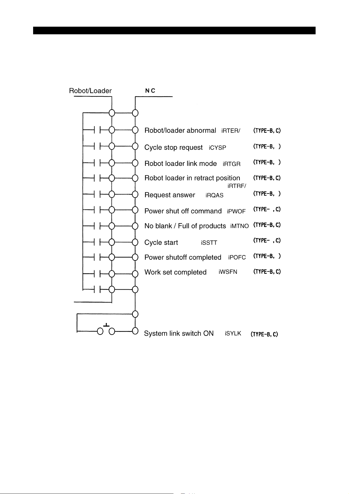
4. List of Input and Output Signals
4-1. Inputs from the Robot/loader to the NC
5309-E P-3
ME61048R0200300040001
Page 15
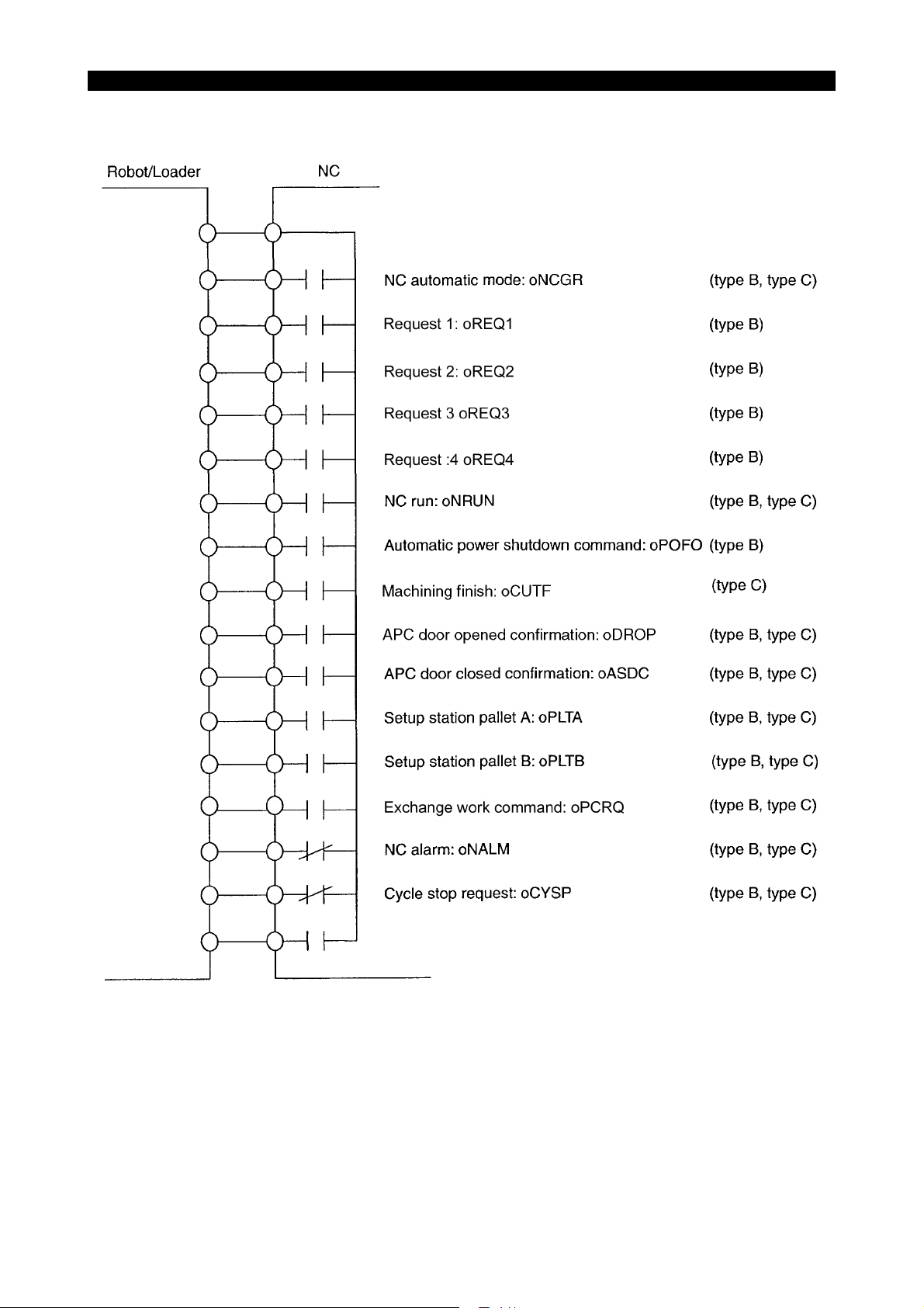
SECTION 1 ROBOT/LOADER INTERFACE TYPES
4-2. Outputs from the NC to the Robot/loader
5309-E P-4
ME61048R0200300050001
Page 16
SECTION 1 ROBOT/LOADER INTERFACE TYPES
5. Description of Signals
5-1. Robot/loader Interface Type B
5-1-1. Inputs from the Robot/loader to the NC (Type B)
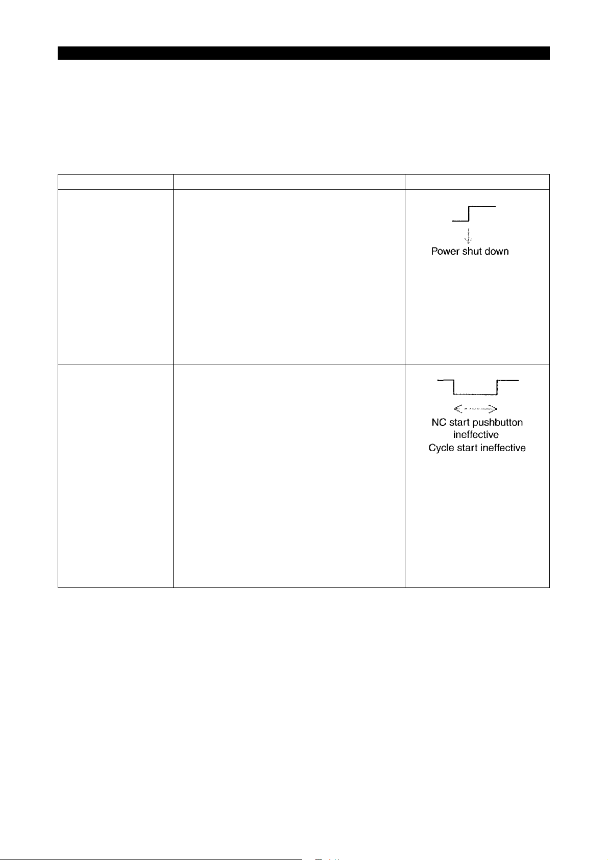
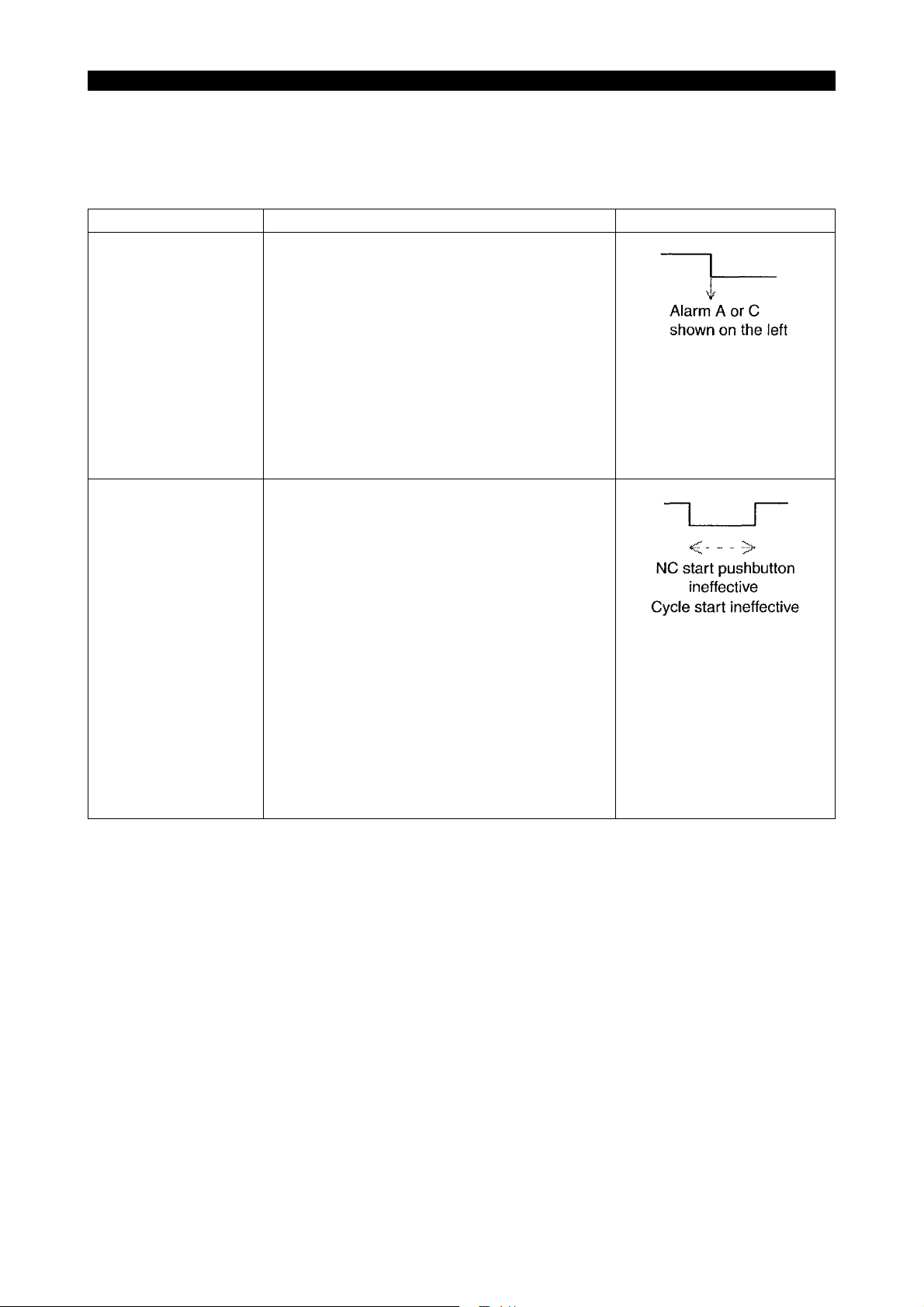
Signal name Description Signal level
Robot/loader abnormal
(iRTER/)
Robot/loader at retract
position
(iRTRF/)
Either of the following alarms occurs when the
"system link switch" is turned ON and this signal is
turned OFF.
The alarm level is changeable with the appropriate parameter.
"8. Robot alarm is made alarm-C." of MC user
parameter ROBOT/LOADER I/F
"0": "1709 Alarm A external"
"1": "3718 Alarm C external"
However, this signal will not be monitored during
warm-up program start wait or during NC operation by warm-up program start.
The NC start pushbutton on the panel and the
"cycle start" command become ineffective when
the "system link switch" is turned ON and this signal is turned OFF.
5309-E P-5
The following alarm occurs when the NC start
pushbutton on the panel is pressed or the "cycle
start" signal is turned ON although NC start is ineffective.
The alarm remains displayed while the NC start
pushbutton on the panel is held down or the "cycle
start" signal is kept ON.
"4720 Alarm DNC start ineffective 12"
However, the above interlock becomes ineffective
when "2. Cycle start: STANDBY POS. I/L is made
ineffective" of MC user parameter ROBOT/
LOADER I/F is set to "1."
Page 17
SECTION 1 ROBOT/LOADER INTERFACE TYPES
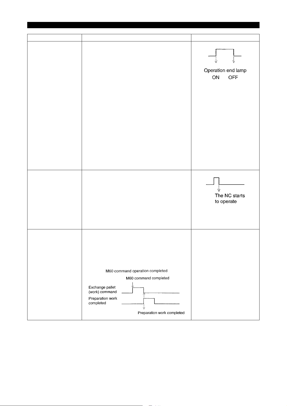
Signal name Description Signal level
No material/full-work
(iMTNO)
Preparation work completed
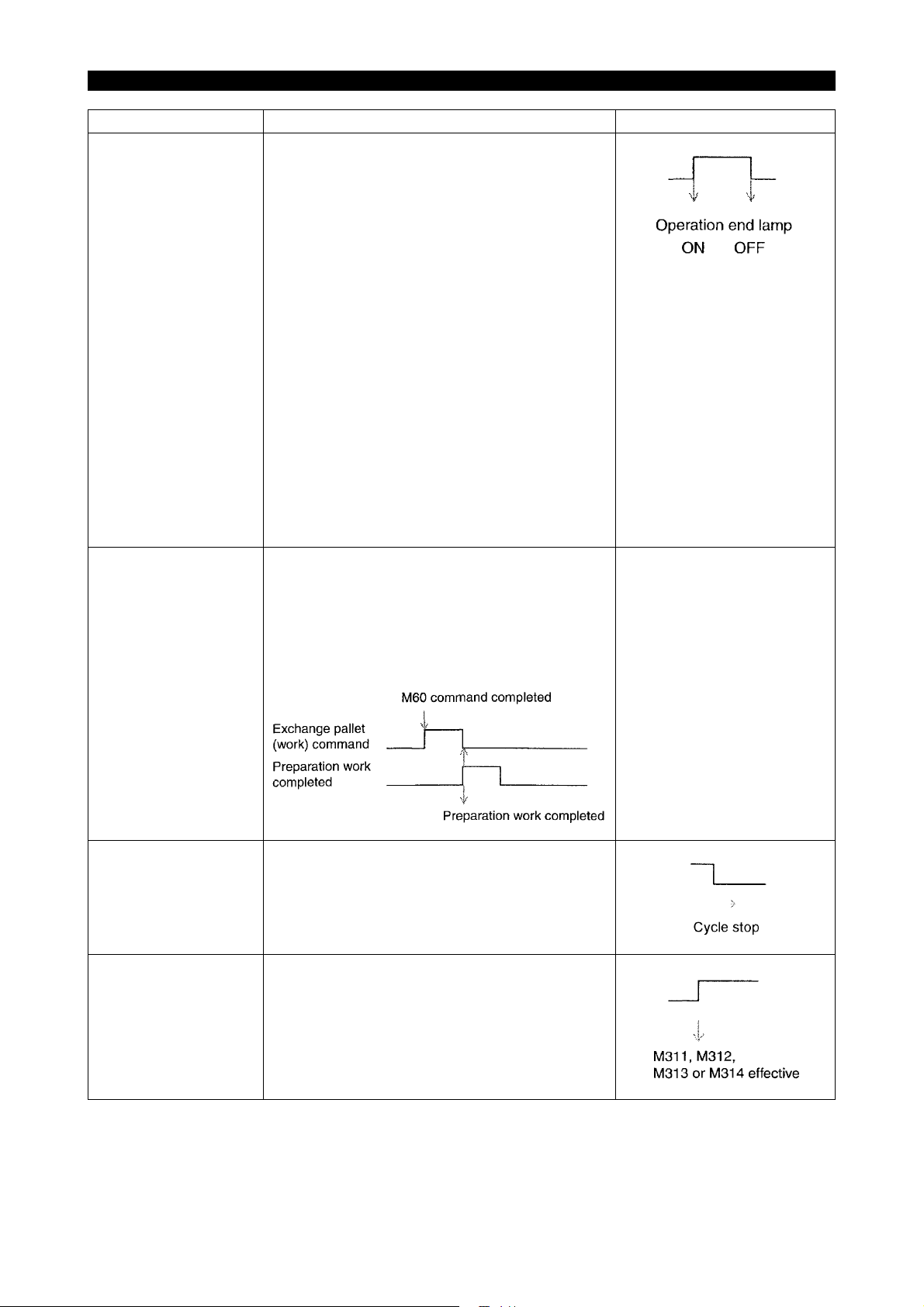
(iWSFN)
The operation end lamp lights while the "system
link switch" is kept ON, the operation end lamp is
effective (described below), and this signal is kept
ON.
MC user parameter
"0" is set at INDICATING LAMP (8. Operation end
lamp is made effect):
Operation end lamp is ineffective.
"1" is set at INDICATING LAMP (8. Operation end
lamp is made effect):
Operation end lamp is effective.
"5. Operation end lamp does not light on by M02/
M30" MC user parameter of ROBOT/LOADER I/F
"0":
The standard operation end lamp function also
becomes effective.
"1":
The standard operation end lamp function
becomes ineffective when the "system link switch"
is turned ON.
The "exchange pallet (work) command" is turned
OFF and work preparation is completed when this
signal is turned ON.
Note: The work preparation completed status will
be retained even if the NC is reset or the power is
turned ON or OFF.
[Time chart]
See the left figure.
5309-E P-6
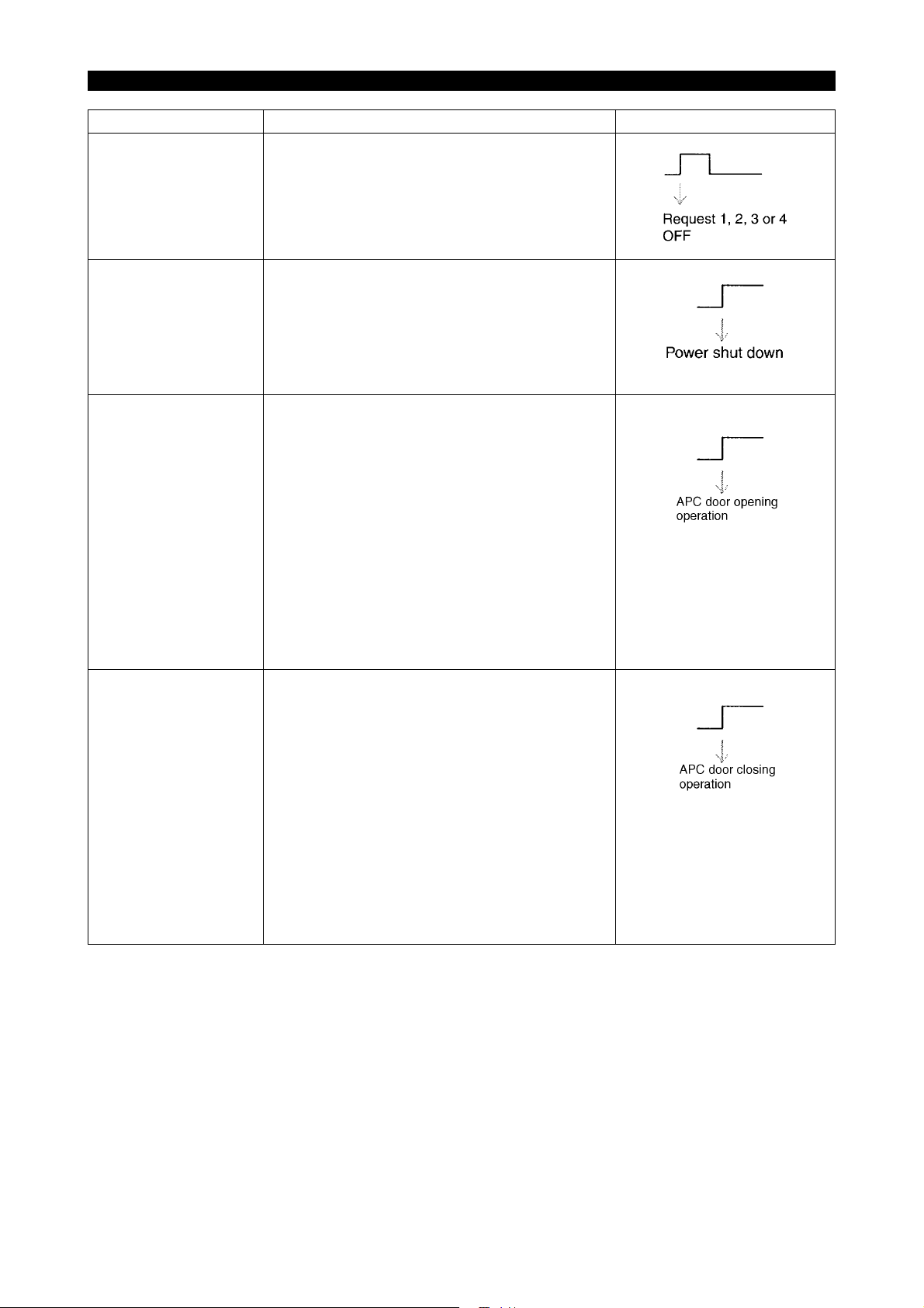
Cycle stop request
(iCYSP)
Robot automatic mode
(iRTGR)
The NC stops the ongoing cycle when this signal
is turned OFF in "automatic mode."
Request 1, 2, 3 or 4 becomes effective when this
signal is turned ON in "automatic mode."
If M311, M312, M313 or M314 is issued when this
signal is OFF, nothing will take place, and an
answer will be given back immediately.
Page 18
SECTION 1 ROBOT/LOADER INTERFACE TYPES
Signal name Description Signal level
Request answer
(iRQAS)
The request output signal (request 1, 2, 3 or 4) is
turned OFF when this signal is turned ON in
"automatic mode."
Turn OFF this signal when the request output signal is turned OFF.
5309-E P-7
Automatic power shutdown completed
(iPOFC)
APC door open command
(iDROC)
APC door close command
(iDRCS)
The power will be shut down automatically when
this signal is turned ON with the "automatic power
shutdown command" output to the robot/loader in
"automatic mode."
For further information, see "Automatic Power
Shutdown Function".
On the machine without APC, the operation door
opens with this signal ON. This signal, however,
becomes ineffective under the following conditions:
• No link mode is established.
• The signal "Robot/loader retract position
iRTRF" is OFF.
(The robot/loader interface is ineffective when
"1" is set at the parameter 4. "DOOR MOVE:
STANDBY POS. I/L IS MADE INEFFECTIVE"
in the MC USER PARAMETER, ROBOTLOADER I/F).
• The machine is equipped with APC.
On the machine without APC, the operation door
closes with this signal ON. This signal, however,
becomes ineffective under the following conditions:
• No link mode is established.
• The signal "Robot/loader retract position
iRTRF" is OFF.
(The robot/loader interface is ineffective when
"1" is set at the parameter 4. "DOOR MOVE:
STANDBY POS. I/L IS MADE INEFFECTIVE"
in the MC USER PARAMETER, ROBOTLOADER I/F).
• The machine is equipped with APC.
Page 19
SECTION 1 ROBOT/LOADER INTERFACE TYPES
5-1-2. Outputs from the NC to the Robot/loader (Type B)
Signal name Description Signal level
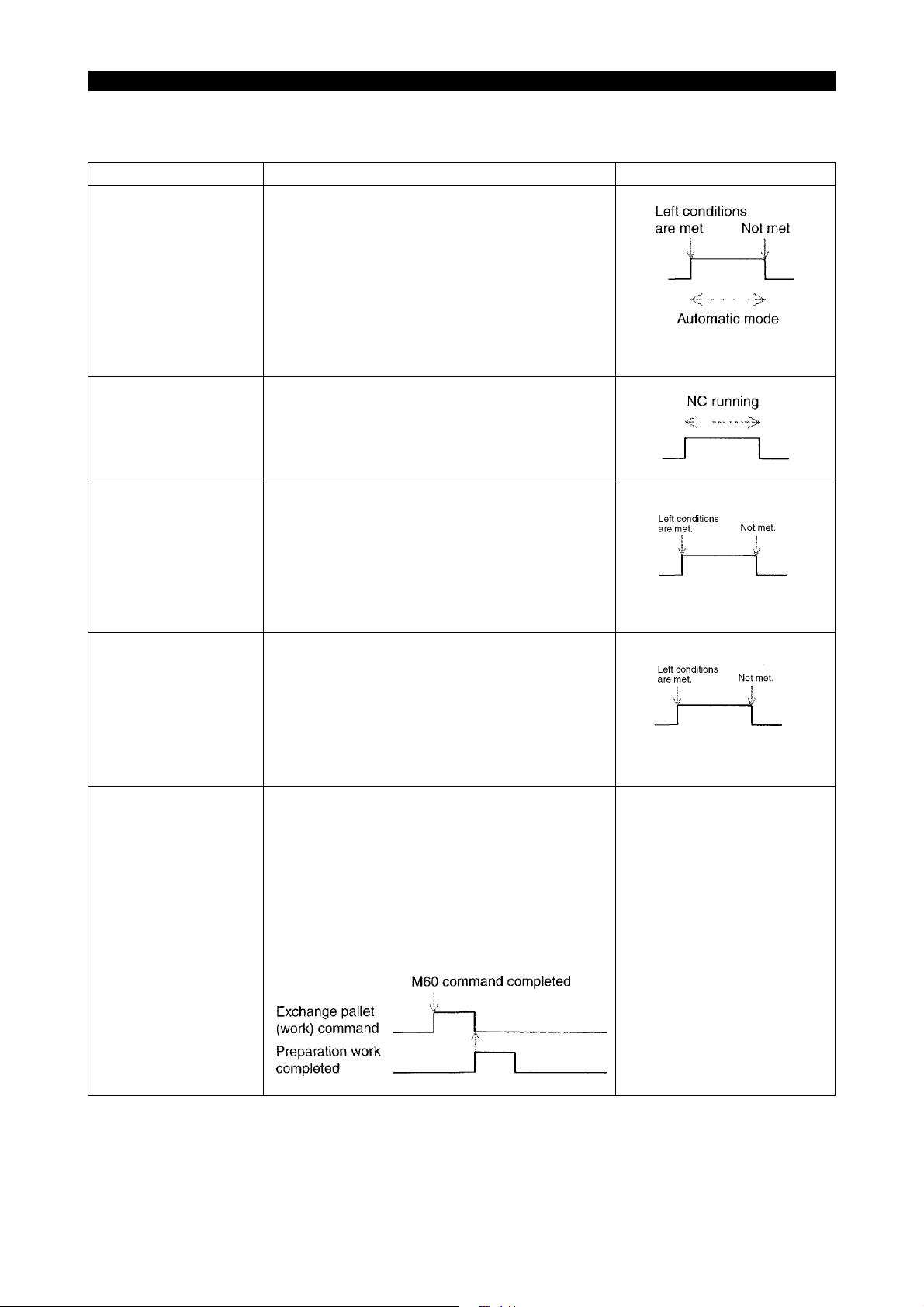
NC automatic mode
(oNCGR)
NC run
(oNRUN)
This signal is turned ON when the following conditions are met:
• Automatic operation mode
• "System link switch" ON
However, this signal will not be turned ON during
warm-up program start wait or during NC operation by warm-up program start.
This signal remains ON during NC operation.
5309-E P-8
A-pallet is outside of
M/C
(oPLTA)
B-pallet is outside of
M/C
(oPLTB)
Exchange pallet (work)
command
(oPCRQ)
This signal comes ON when all the following conditions are met:
• Pallet B mode is ON.
• Pallet A mode is ON when "1" is set at "B pal-
let in M/C side, when APC Seq. No.1" of the
machine user parameter CHUCK, SIT CONFIRMATION, TAILSOTCK.
This signal comes ON when all the following conditions are met:
• Pallet A mode is ON.
• Pallet B mode is ON when "1" is set at "B pal-
let in M/C side, when APC Seq. No.1" of the
machine user parameter CHUCK, SIT CONFIRMATION, TAILSOTCK.
This signal is turned ON upon completion of the
M60 command operation in automatic mode.
This signal is turned OFF with the "preparation
work completed" signal turned ON.
This signal will be retained even if the NC is reset
or the power is turned ON or OFF.
APC sequence No.
APC sequence No.
See the time chart shown on
the left.
[Time chart]
Page 20
SECTION 1 ROBOT/LOADER INTERFACE TYPES
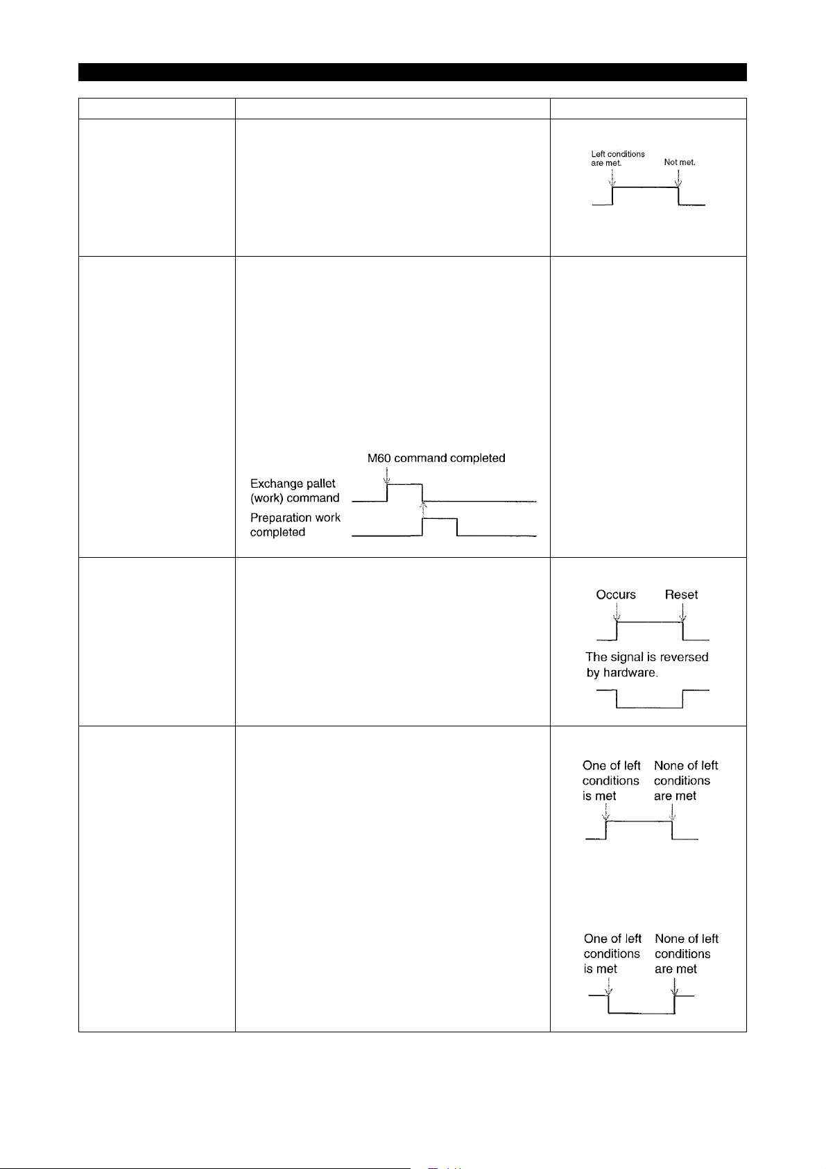
Signal name Description Signal level
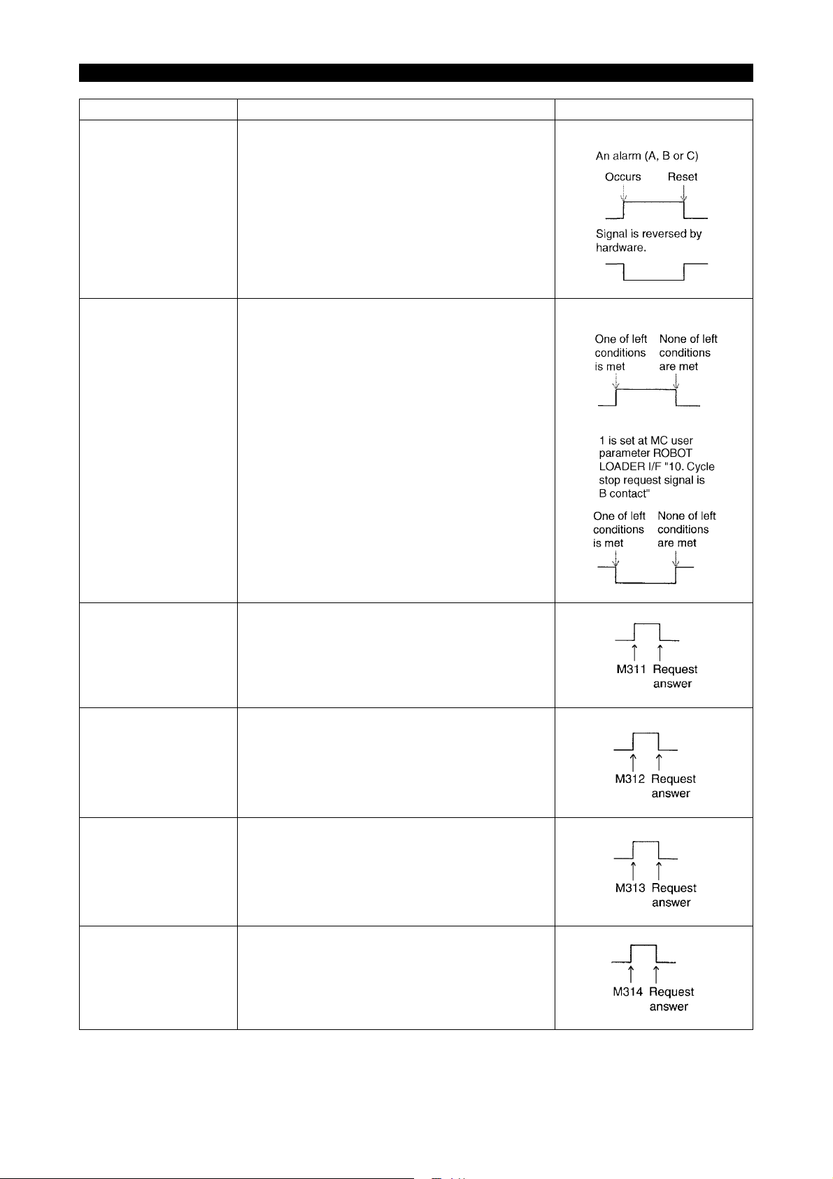
NC alarm
(oNALM)
This signal is usually OFF, but will be turned ON
when an alarm (A, B or C) occurs. NC reset will
turned OFF the signal again.
The signal will be reversed into a B contact by
hardware.
An alarm (A, B or C)
5309-E P-9
Cycle stop request
(oCYSP)
Request 1
(M311)
oREQ1
Request 2
(M312)
oREQ2
This signal is turned ON in one of the following
cases. The signal is turned OFF in other cases:
• When the count of the NC work counter is full.
• When the tool can no longer serve.
• When the "no material/full-work" signal is
turned ON with the "system link switch"
turned ON.
Whenever "1" is set at the MC user parameter
ROBOT LOADER I/F "10. Cycle stop request signal is B contact", this signal is turned ON. However, it will be turned OFF in one of the above
cases. (B contact output)
This signal is turned ON with the M311 command
when the "robot automatic mode" signal is turned
ON in "automatic mode."
An answer will be given back with the request
answer signal turned ON, and this signal will be
turned OFF.
Same as request 1, except that the M command is
M312.
Request 3
(M313)
oREQ3
Request 4
(M314)
oREQ4
Same as request 1, except that the M command is
M313.
Same as request 1, except that the M command is
M314.
Page 21

SECTION 1 ROBOT/LOADER INTERFACE TYPES
Signal name Description Signal level
Automatic power shutdown command
oPOFO
This signal is turned ON after the time set by “6.
Power shutdown time” of MC user parameter
POWER SAVE/SHUTDOWN passes away if all of
the following conditions are met when the automatic power shutdown effective parameter (“3.
‘Automatic Power Shutdown’ is made effective” of
MC user parameter POWER SAVE/SHUTDOWN)
or automatic power shutdown ON/OFF switch is
turned ON in "automatic mode":
• Single block OFF in automatic operation
mode
• During existence of the machining cycle com-
pleted signal or alarm A, B or C
When "Automatic power shutdown MC alone" (“9.
Automatic power shutdown MC alone” of MC user
parameter ROBOT LOADER I/F) is "1", this signal
will not be output, and the power to the machine
will be shut down.
5309-E P-10
For further information, see "SECTION 7 WORK
SET ST AUTO DOOR SPEC."
Page 22
SECTION 1 ROBOT/LOADER INTERFACE TYPES
The conditions for outputting the operation door open/close confirmation signals vary with the specifications as described below:
a. With the operation door auto open/close spec
For details regarding the operation door auto open/close spec, refer to "Section 4 Operation
Door Auto Open/Close Spec".
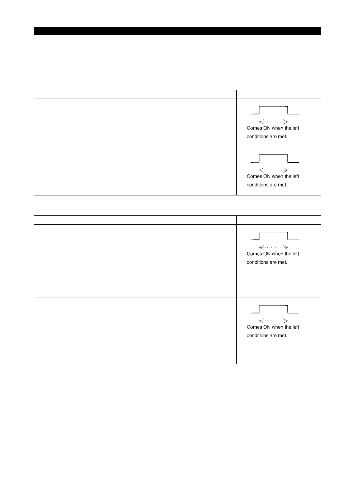
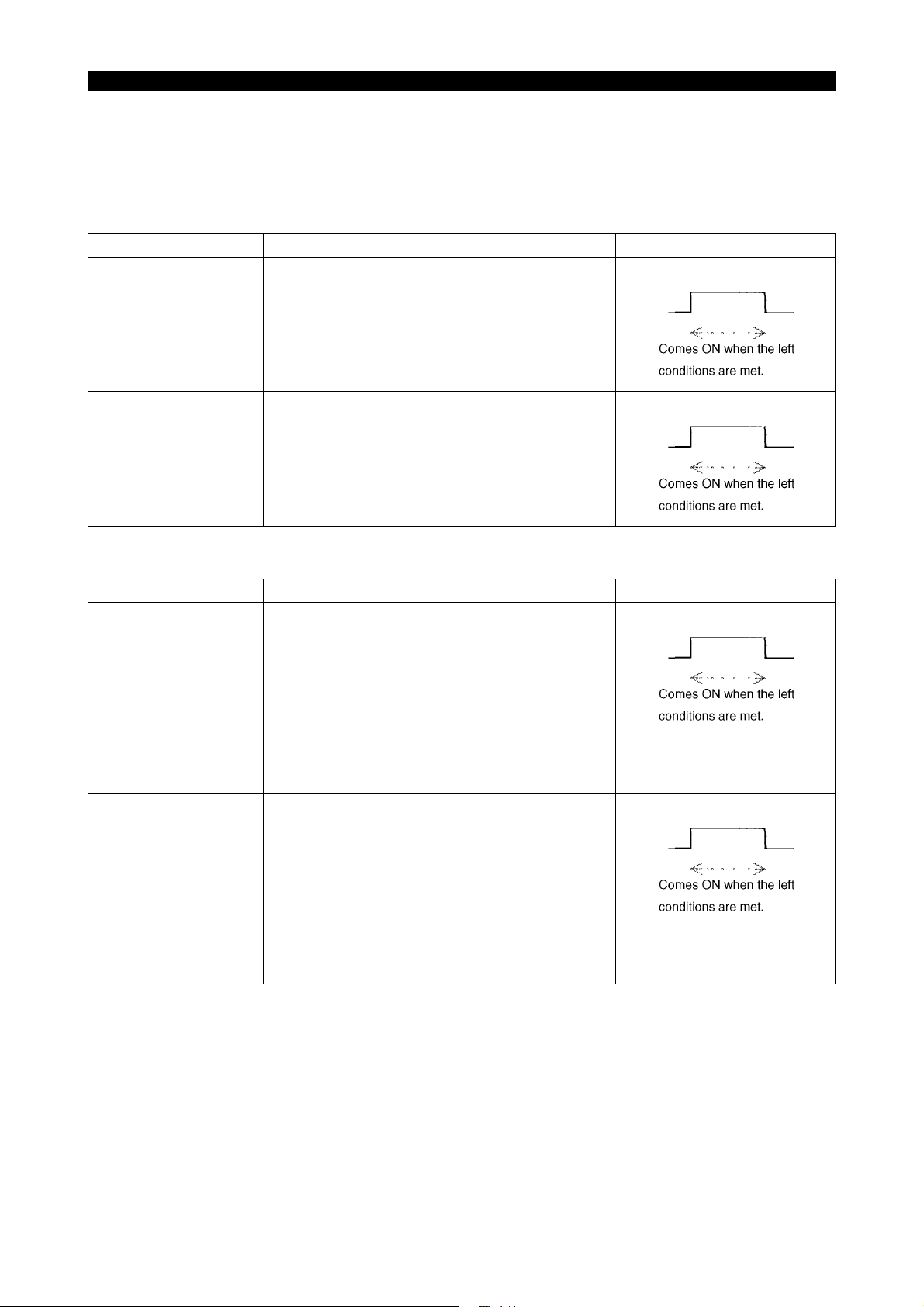
Signal name Description Signal level
Operation door open
(oDROP)
This signal comes ON when the following conditions are met:
• Operation door open output ON
• Operation door open confirmation ON
• Operation door close confirmation OFF
Operation door close
(oDRCP)
This signal comes ON when the following conditions are met:
• Operation door close output ON
• Operation door close confirmation ON
• Operation door open confirmation OFF
5309-E P-11
b. Without the operation auto door spec
Signal name Description Signal level
Operation door open
(oDROP)
This signal comes ON when the following conditions are met:
• Operation door open confirmation ON *
• Operation door close confirmation OFF
* Without the operation door auto open/close, The
signal "Operation door open confirmation" is provided as option.
Operation door close
(oDRCP)
This signal comes ON when following conditions
are met:
• Front door open confirmation ON
• Front door close confirmation OFF*
* Without the operation door auto open/close
spec, The signal "Operation door close confirmation" is provided as option.
Page 23
SECTION 1 ROBOT/LOADER INTERFACE TYPES
5-2. Robot/loader Interface Type C
5-2-1. Inputs from the Robot/loader to the NC (Type C)
Signal name Description Signal level
Robot/loader abnormal
(iRTER/)
Robot/loader at retract
position
(iRTRF/)
Either of the following alarms occurs when the
"system link switch" is turned ON and this signal is
turned OFF. The alarm level is changeable with
the appropriate parameter.
"8. Robot alarm is made alarm C." of MC user
parameter ROBOT LOADER I/F
"0": "1709 Alarm A external"
"1": "3718 Alarm C external"
However, this signal will not be monitored during
warm-up program start wait or during NC operation by warm-up program start.
The NC start pushbutton on the panel and the
"cycle start" command become ineffective when
the "system link switch" is turned ON and this signal is turned OFF.
5309-E P-12
The following alarm occurs when the NC start
pushbutton on the panel is pressed or the "cycle
start" signal is turned ON although NC start is ineffective.
The alarm remains displayed while the NC start
pushbutton on the panel is held down or the "cycle
start" signal is kept ON.
"4720 Alarm D NC start ineffective 12"
However, the above interlock becomes ineffective
when "2. Cycle start: STANDBY POS. I/L is made
ineffective" of MC user parameter ROBOT
LOADER I/F is "1".
Page 24

SECTION 1 ROBOT/LOADER INTERFACE TYPES
Signal name Description Signal level
Automatic power shutdown command
(iPWOF)
The power is automatically shut down after the
time set by "6. Automatic power shutdown timer"
of MC user parameter POWER SAVE/SHUTDOWN passes away if all of the following conditions are met when this signal is turned ON in
"automatic mode":
• Single block OFF in automatic operation
mode
• During existence of the machining cycle com-
pleted signal or alarm A, B or C
This signal is not affected by the automatic power
shutdown effective switch ("3. 'Automatic Power
Shutdown' is made effective" of MC user parameter POWER SAVE/SHUTDOWN) or automatic
power shutdown ON/OFF switch.
When "6. Automatic Power shutdown switch is
made effective" of MC user parameter ROBOT
LOADER I/F is "1", this function becomes effective only when the automatic power shutdown
effective switch ("3. 'Automatic Power Shutdown'
is made effective" of MC user parameter POWER
SAVE/SHUTDOWN) is set to "1" or the automatic
power shutdown ON/OFF switch is set to automatic power shutdown ON.
When "4. Alarm is added as a requirement for
Shutdown" of MC user parameter POWER SAVE/
SHUTDOWN is "0", the occurrence of an alarm A
or B is not included in the automatic power shutdown conditions.
5309-E P-13
For further information, see "SECTION 7 WORK
SET ST AUTO DOOR SPEC."
Page 25
SECTION 1 ROBOT/LOADER INTERFACE TYPES
Signal name Description Signal level
No material/full-work
(iMTNO)
Cycle start
(iSSTT)
The operation end lamp lights while the "system
link switch" is kept ON, the operation end lamp is
effective (described below), and this signal is kept
ON.
MC user parameter
"0" is set at INDICATING LAMP, "8. Operation end
lamp is made effect":
Operation end lamp is ineffective.
"1" is set at INDICATING LAMP, "8. Operation end
lamp is made effect":
Operation end lamp is effective.
MC user parameter
"5. Operation end lamp does not light on by M02/
M30" of ROBOT LOADER I/F
"0":
The standard operation end lamp function also
becomes effective.
"1":
The standard operation end lamp function
becomes ineffective when the "system link switch"
is turned ON.
The NC starts to operate on the falling edge of this
signal when all of the following conditions are met:
5309-E P-14
Preparation work completed
(iWSFN)
• "Automatic mode"
• "Robot/loader at retract position" ON
(The "robot/loader at retract position interlock
be-comes ineffective when "2. Cycle start:
STANDBY POS. I/L is made ineffective" of
MC user parameter ROBOT LOADER I/F is
"1".)
The "exchange pallet (work) command" is turned
OFF and work preparation is completed when this
signal is turned ON.
Note: The work preparation completed status will
be retained even if the NC is reset or the power is
turned ON or OFF.
See the figure shown on the
left.
Page 26

SECTION 1 ROBOT/LOADER INTERFACE TYPES
Signal name Description Signal level
APC door open command
(iDROC)
The APC door opens when this signal comes ON.
However, the door does not open in any of the following cases:
• The link mode is not established.
• The APC door opening M command is being
executed.
• The APC cycle is being conducted or the
APC is not in the start position.
• An alarm A is occurring.
• The power save mode is established.
• Machine lock is ON.
• The robot/loader retract position signal
iRETRF_b is OFF.
(This interlock signal is ignored when "1" is
set at "4. Door move: STANDBY POS. I/L is
made ineffective" of the machine user parameter ROBOT LOADER I/F).
5309-E P-15
APC door close command
(iDRCS)
For details, refer to SECTION 7 "WORK SET ST
AUTO DOOR SPEC."
The APC door opens when this signal comes ON.
However, the door does not open in any of the following cases:
• The link mode is not established.
• The APC door opening M command is being
executed.
• The APC cycle is being conducted or the
APC is not in the start position.
• An alarm A is occurring.
• The power save mode is established.
• Machine lock is ON.
• The robot/loader retract position signal
iRETRF_b is OFF.
(This interlock signal is ignored when "1" is
set at "4. Door move: STANDBY POS. I/L is
made ineffective" of the machine user parameter ROBOT LOADER I/F).
For details, refer to SECTION 7 "WORK SET ST
AUTO DOOR SPEC."
Page 27

SECTION 1 ROBOT/LOADER INTERFACE TYPES
5-2-2. Outputs from the NC to the Robot/loader (Type C)
Signal name Description Signal level
NC automatic mode
(oNCGR)
NC running
(oNRUN)
This signal is turned ON when the following conditions are met:
• Automatic operation mode
• "System link switch" ON
However, this signal will not be turned ON during
warm-up program start wait or during NC operation by warm-up program start.
This signal remains ON during NC operation.
5309-E P-16
Machining cycle completed
(oCFUTF)
This signal is turned ON upon completion of NC
machining (at the end of M02, M30 or schedule
program).
This signal is turned OFF on the rising edge of the
cycle star switch and NC run signal.
This signal will be retained even if the NC is reset
or the power is turned ON or OFF.
This signal does not come ON with M02 or M30
by warm-up program start. This signal does not go
OFF by warm-up program start because it is not
regarded as NC running.
[Machining time chart]
See the time chart shown on
the left.
A-pallet is outside of
M/C
(oPLTA)
This signal comes ON when all the following conditions are met:
• Pallet B mode is ON.
• Pallet A mode is ON when "1" is set at "B pal-
let in M/C side, when APC Seq. No.1" of the
machine user parameter CHUCK, SIT CONFIRMATION, TAILSOTCK.
APC sequence No.
Page 28
SECTION 1 ROBOT/LOADER INTERFACE TYPES
Signal name Description Signal level
B-pallet is outside of
M/C
(oPLTB)
This signal comes ON when all the following conditions are met:
• Pallet A mode is ON.
APC sequence No.
• Pallet B mode is ON when "1" is set at "B pal-
let in M/C side, when APC Seq. No.1" of the
machine user parameter CHUCK, SIT CONFIRMATION, TAILSOTCK.
Exchange pallet (work)
command
(oPCRQ)
This signal is turned ON upon completion of the
M60 command operation in automatic mode. This
signal is turned OFF with the "preparation work
completed" signal turned ON.
This signal will be retained even if the NC is reset
or the power is turned ON or OFF.
This signal will be turned OFF in a mode other
than automatic mode.
[Time chart]
See the time chart shown on
the left.
5309-E P-17
NC alarm
(oNALM)
Cycle stop request
(oCYSP)
This signal is usually OFF, but will be turned ON
when an alarm (A, B or C) occurs. NC reset will
turn OFF the signal again.
The signal will be reversed into a B contact by
hardware. The signal is reversed by hardware.
This signal is turned ON in one of the following
cases.
The signal will be turned OFF in none of the following cases:
• When the count of the NC work counter is full.
• When the tool can no longer serve.
• When the "no material/full-work" signal is
turned ON with the "system link switch"
turned ON.
Whenever "10. Cycle stop request signal is B contact" of MC user parameter ROBOT LOADER I/F
is "1", this signal is turned ON. However, it will be
turned OFF in one of the above cases. (B contact
output)
An alarm (A, B or C)
"1" is set at MC user parameter ROBOT LOADER I/F"10.
Cycle stop request signal is B
contact".
Page 29

SECTION 1 ROBOT/LOADER INTERFACE TYPES
Signal name Description Signal level
Work condition 1
oREQ1
Work condition 2
oREQ2
Work condition 3
oREQ3
Work condition 4
oREQ4
This signal comes ON when M311 is issued
(immediate answer).
This signal goes OFF at the rising edge of the
cycle start signal or NC running signal. (The OFF
conditions are the same with those of the machining end signal.)
This signal remains effective after NC reset or
power ON/OFF.
This signal comes ON when M312 is issued
(immediate answer).
This signal goes OFF at the rising edge of the
cycle start signal or NC running signal. (The OFF
conditions are the same with those of the machining end signal.)
This signal remains effective after NC reset or
power ON/OFF.
This signal comes ON when M313 is issued
(immediate answer).
This signal goes OFF at the rising edge of the
cycle start signal or NC running signal. (The OFF
conditions are the same with those of the machining end signal.)
This signal remains effective after NC reset or
power ON/OFF.
This signal comes ON when M314 is issued
(immediate answer).
This signal goes OFF at the rising edge of the
cycle start signal or NC running signal. (The OFF
conditions are the same with those of the machining end signal.)
This signal remains effective after NC reset or
power ON/OFF.
5309-E P-18
Page 30
SECTION 1 ROBOT/LOADER INTERFACE TYPES
The conditions for outputting the APC door open/close confirmation signals vary with the specifications as described below:
a. With the work set ST auto door spec
For details regarding the specifications for the setup station door auto open/close, refer to "Section 7 Work Set ST Auto Door Spec"
Signal name Description Signal level
APC door open
(oDROP)
This signal comes ON when the following conditions are met:
• APC door open output ON
• APC door open confirmation ON
• APC door close confirmation OFF
5309-E P-19
APC door close
(oDRCP)
This signal comes ON when the following conditions are met:
• APC door close output ON
• APC door close confirmation ON
• APC door open confirmation OFF
b. Without the work set ST auto door spec
Signal name Description Signal level
APC door open
(oDROP)
This signal comes ON when the following conditions are met:
• APC door open confirmation ON *
• APC door close confirmation OFF
* Without work set ST auto spec, the APC door
open confirmation is provided as an optional
specification.
APC door close
(oDRCP)
This signal comes ON when following conditions
are met:
• APC door open confirmation ON *
• This signal comes ON when APC door close
confirmation is ON.
* Without work set ST auto spec, the APC door
open confirmation is provided as an optional
specification.
Page 31

6. Interlock
6-1. Axis Interlock
This interlock function disables movement of X, Y, and Z-axes when the system link switch is ON
and the robot/loader retract position signal is OFF.
However, this interlock is ignored when "1" is set at "3. Axis move: STANDBY POS. I/L is made ineffective" of the machine user parameter ROBOT LOADER I/F.
* For the machine with APC, the X, Y, Z-axis can be moved even if the robot/loader retract position
signal is OFF.
6-2. APC Interlock
(1) The following alarm occurs when the APC is in operation (during a cycle), the "system link
switch" is turned ON, and the robot/loader at retract position signal is turned OFF:
"1744 Alarm A Robot/loader at retract position 10"
However, the above interlock will be ignored when "3. Axis move: STANDBY POS. I/L is made
ineffective" of MC user parameter ROBOT LOADER I/F is "1".
5309-E P-20
SECTION 1 ROBOT/LOADER INTERFACE TYPES
(2) When the "system link switch" is turned ON and the robot/loader at retract position signal is
turned OFF during execution of the M60 command, the APC cycle does not begin, and the
above-mentioned alarm occurs.
However, the above interlock will be ignored when "3. Axis move: STANDBY POS. I/L is made
ineffective" of MC user parameter ROBOT LOADER I/F is "1".
Page 32

SECTION 1 ROBOT/LOADER INTERFACE TYPES
7. Work Condition Display Function
When the indication of work condition display spec is provided for the ROBOT LOADER I/F type C,
"1" is set at the following parameter.
Machine user parameter ROBOT LOADER I/F
13 Indication of work condition is made effective.
0 ... Indication of work condition ineffective
1 ... Indication of work condition effective
If "1" is set at the above parameter of ROBOT/LOADER I/F type C, the following signals become
effective.
• Work condition 1 (oREQ1)
• Work condition 2 (oREQ2)
• Work condition 3 (oREQ3)
• Work condition 4 (oREQ4)
Note
The robot loader I/F type B request 1 (oREQ1) to request 4 (oREQ4) signals are used (shared).
However, their ON/OFF conditions and M command answer conditions are different.
5309-E P-21
Note
This specification is ineffective for ROBOT LOADER I/F type B. For the robot loader I/F type B, the
existing request 1 (oREQ1) to 4 (oREQ4) can be selected.
Specifications: For details of the specifications, refer to 5-2-2. Output from the NC to Robot/Loader
(Type C).
Page 33

8. Parameters
5309-E P-22
SECTION 1 ROBOT/LOADER INTERFACE TYPES
ME61048R0200300130001
Page 34

SECTION 1 ROBOT/LOADER INTERFACE TYPES
9. Automatic Power Shutdown
9-1. Effective Conditions
Any of the following states is called an "automatic power shutdown ON state".
(1) Robot/loader interface type C
a. In "automatic mode"
When the "automatic power shutdown command iPWOF" is input from the robot/loader.
[Supplement]
This function is not affected by the automatic power shutdown effective parameter ("3. 'Automatic
Power Shutdown' is made effective" of MC user parameter POWER SAVE/SHUTDOWN) or automatic power shutdown ON/OFF switch.
When "6. Automatic Power shutdown Switch is made effective" of MC user parameter ROBOT
LOADER I/F is "1", this function becomes effective only when the automatic power shutdown
effective parameter ("3. 'Automatic Power Shutdown' is made effective" of MC user parameter
POWER SAVE/SHUTDOWN) is "1" or the automatic power shutdown ON/OFF switch is set to
automatic power shutdown ON (iPOFF)
5309-E P-23
b. In a mode other than "automatic mode"
When the automatic power shutdown effective parameter ("3. 'Automatic Power Shutdown'
is made effective" of MC user parameter POWER SAVE/SHUTDOWN) is "1" or the automatic power shutdown ON/OFF switch is set to automatic power shutdown ON (iPOFF).
(2) Robot/loader interface type B
a. In "automatic mode" when automatic power shutdown robot/loader interlocking is desig-
nated:
When "automatic power shutdown completed iPOFC" is input from the robot/loader while
the "automatic power shutdown command iPOFO" is output to the robot/loader.
* Automatic power shutdown robot/loader interlocking designation:
When the automatic power shutdown MC alone designation parameter ("9. Automatic
power shutdown MC alone" of MC user parameter ROBOT LOADER I/F) is "0".
The "automatic power shutdown command iPOFO" will be output in the power shutdown
state described in 8-2. Description of the Function when the automatic power shutdown
effective parameter ("3. 'Automatic Power Shutdown' is made effective" of MC user parameter POWER SAVE/SHUTDOWN) is "1" or the automatic power shutdown ON/OFF switch
is set to automatic power shutdown ON (iPOFF) in "automatic mode" with automatic power
shutdown robot/loader interlocking designated.
b. In a case other than automatic power shutdown MC alone designation or "automatic mode"
When the automatic power shutdown effective parameter ("3. 'Automatic Power Shutdown'
is made effective" of MC user parameter POWER SAVE/SHUTDOWN) is "1" or the automatic power shutdown ON/OFF switch is set to automatic power shutdown ON (iPOFF).
Page 35

9-2. Description of the Function
In "automatic operation mode" and "single block OFF" with "automatic power shutdown ON," the
power will be shut down automatically after the duration of one of the following states reaches the
time set by 6 "automatic power shutdown timer" of MC user parameter POWER SAVE/SHUTDOWN:
(1) Schedule end during schedule program selection.
(2) After program end (M2 or M30) execution is completed except during schedule program selec-
tion.
(3) When an alarm A, B or C occurs.
(This function is effective only when 4 "Alarm is added as a requirement for Shutdown" of MC
user parameter POWER SAVE/SHUTDOWN is "1".)
- When an alarm A occurs and the setting of the automatic power shutdown timer is 30 seconds or less, the power will be shut down 30 seconds after the alarm A occurs.
- When an alarm B occurs, the main spindle will come to a stop 10 seconds after it is confirmed that the all-axis in-position signal is ON, and the power will be shut down after the
time of the automatic power shutdown timer passes away.
However, if the setting of the automatic power shutdown timer is 30 seconds or less, the
power will be shut down 30 seconds after the main spindle comes to a stop.
- When an alarm C occurs, the power will be shut down after the time of the automatic power
shutdown timer passes away following turning OFF of NC run during schedule program
selection. This function does not become activated in cases except during schedule program selection.
5309-E P-24
SECTION 1 ROBOT/LOADER INTERFACE TYPES
MC user parameter No. 2 Power save/power shutdown
4 Alarm is added as a requirement for Shutdown.
6 Automatic power shutdown timer
Command: Setting, addition
Initial value: 0
Minimum value: 10
Maximum value: 3600
Unit: Second
(4) Other conditions
Auto power shutoff is disabled during file operation.
If auto power shutoff command is issued during file operation, the NC activates the following
alarm and waits until the file operation ends. Then, the NC releases the alarm and executes
auto power shutoff.
"4706 Alarm DAuto power shut-off impossible"
Page 36

9-3. Parameters
5309-E P-25
SECTION 1 ROBOT/LOADER INTERFACE TYPES
ME61048R0200300160001
Page 37

10. Input/Output Bit
The following screen allows you to check the input states of various switches mounted in the
machine and output states of the lamps, relays, and solenoid valves.
Both input and output states are displayed in reverse video, indicating that their signals are ON. For
the other input/output signals and the method of using I/O monitors, refer to OSP-P200M MD-H/MAH series Maintenance Manual.
Procedure :
1 Press the (DIAGNOSE) key among the vertical function keys at the right end of the
screen.
5309-E P-26
SECTION 1 ROBOT/LOADER INTERFACE TYPES
ME61048R0200300170001
Page 38

5309-E P-27
SECTION 1 ROBOT/LOADER INTERFACE TYPES
2 Press the (I/O MONITOR) key in the diagnosis menu. The I/O monitor starts up.
ME61048R0200300170002
Page 39

3 The following I/O monitor screen appears.
5309-E P-28
SECTION 1 ROBOT/LOADER INTERFACE TYPES
Data layout change (vertical, horizontal)
Screen change between logical and physical
Displays the Slave station display screen.
Displays the Search screen.
In the status display of bit data, the active bit (ON) is expressed with a red circle.
Data type (Selectable from
among bit, 2 Byte and 4 Byte)
ME61048R0200300170003
Page 40

SECTION 1 ROBOT/LOADER INTERFACE TYPES
Input bit
Addr Bit Label Comment
0025 01 iRTER_b Robot-IF alarm
0025 02 iCYSP Robot-IF cycle stop request
0025 03 iRTGR Robot-IF ROBOT LINK ON
0025 04 iRTRF_b Robot-IF retract position
0025 05 iRQAS Robot-IF request answer
0025 06 iPWOF Robot-IF auto shout doun request
0025 07 iMTNO Robot-IF No work/ Full work
0025 08 iSSTT Robot-IF cycle start command
0025 09 iPOFC Robot-IF auto shout down FIN
0025 10 iWSFN Robot-IF work set FIN
0025 14 iDROC Robot-IF auto door open command
0025 15 iDRCS Robot-IF auto door close command
0016 15 iSYLK Robot-IF SYSTEM LINK ON
Output bit
5309-E P-29
Addr Bit Label Comment
0529 0 oNCGR Robot-IF NC system link mode
0529 01 oNRUN Robot-IF NC run status
0529 02 oPOFO Robot-IF auto power shot down command
0529 03 oCUTF Robot-IF program end
0529 05 oPLTA Robot-IF A-pallet is outside of M/C
0529 06 oPLTB Robot-IF B-pallet is outside of M/C
0529 07 oPCRQ Robot-IF pallet change request
0529 08 oNALM Robot-IF NC alarm status
0529 09 oCYSP Robot-IF cycle stop request
0529 11 oREQ1 Robot-IF request 1
0529 12 oREQ2 Robot-IF request 2
0529 13 oREQ3 Robot-IF request 3
0529 14 oREQ4 Robot-IF request 4
0525 14 oDROP Robot-IF auto door open confirm
0525 15 oDRCP Robot-IF auto door close confirm
Page 41

SECTION 2 CHUCK (JIG) CONTROL
SECTION 2 CHUCK (JIG) CONTROL
1. No. 1 Chuck (Jig)
1-1. Clamping Modes
The chuck clamps the outer or inner diameter of the workpiece.
OD clamping ...The chuck clamps the workpiece as it closes and unclamps as it opens.
ID clamping ...The check clamps the workpiece as it opens and unclamps as it closes.
The clamping modes can be switched using the following parameter.
MC UNSER PARAMETER No.15-1 CHUCK, SIT CONFIRMATION, TAILSTOCK
1 The chuck clamps the inner diameter of the workpiece.
0...The chuck clamps the outer diameter of the workpiece.
1...The chuck clamps the inner diameter of the workpiece.
1-2. Chuck clamp/unclamp commands
5309-E P-30
The chuck clamp/unclamp commands include pushbutton input, M code and robot/loader commands.
(1) Pushbutton input commands
Press the Chuck Clamp button to clamp.
Press the Chuck Unclamp button to unclamp.
Conditions for executing the commands:
All of the following conditions should be met to execute the commands.
• The System Link switch is off (in case of the robot/loader interface).
• The NC is not active.
Note that the pushbutton input commands are only effective when the M code Chuck
Clamp/Unclamp Pushbuttons Validate command (M35) has been given.
(The M code Pushbuttons Validate command is cancelled by the M02/M03 command
or by pressing the RESET (or MODE REST) button).
• Alarm A has not been pending, the power not saved, and the machine not locked.
• The spindle is at rest.
This condition only applies to the Chuck Unclamp command.
• The operation door is closed.
Chuck Clamp command: Effective when the following parameter has been set to "1."
MC UNSER PARAMETER No.15-3 CHUCK, SIT CONFIRMATION, TAILSTOCK
25 The Work Clamp PB is ineffective when the door is open.
0...The Work Clamp PB is effective even when the door is open.
1...The Work Clamp PB is ineffective when the door is open.
Page 42

5309-E P-31
SECTION 2 CHUCK (JIG) CONTROL
Chuck Unclamp command: Effective when the following parameter has been set to
"1."
MC UNSER PARAMETER No.15-5 CHUCK, SIT CONFIRMATION, TAILSTOCK
57 The Work Unclamp PB is ineffective when the door is open.
0...The Work Unclamp PB is effective even when the door is open.
1...The Work Unclamp PB is ineffective when the door is open.
Note: This does not depend on the NC operation mode.
[Single Chuck Clamp/Unclamp PB mode]
The single chuck clamp/unclamp PB mode is made effective using the following
parameter.
MC UNSER PARAMETER No.15-1 CHUCK, SIT CONFIRMATION, TAILSTOCK
11 Chuck clamp/unclamp PB 1 button spec
0...Two chuck clamp/unclamp pushbuttons
1...A single chuck clamp/unclamp PB
If the Chuck Clamp pushbutton is pressed when the Chuck Unclamp command has
been given, the chuck clamps the workpiece. If it is pressed when the Chuck Clamp
command has been given, the chuck unclamps the workpiece.
If the Chuck Clamp PB is pressed when the workpiece is being clamped, the chuck
stops clamping and starts unclamping. Similarly, if the Chuck Clamp PB is pressed
when the workpiece is being unclamped, the chuck stops unclamping and starts
clamping.
Chuck Clamp PB
Chuck Clamp signal
Chuck Unclamp signal
ME61048R0200400020001
Page 43

SECTION 2 CHUCK (JIG) CONTROL
(2) M code commands
M code Content
M148 Clamps with No. 1 chuck (jig).
M149 Unclamps with No. 1 chuck (jig).
• The Chuck Clamp command is answered back when the workpiece is completely clamped
(further described later).
• The Chuck Unclamp command is answered back when the workpiece is completely
unclamped (further described below).
• The Answer Ignore command is enabled when the operating time reduction mode has
been selected.
M149 M301.......Answered back without confirming the completion of clamping.
:
M302................Answered with confirmation.
M148 M301.......Answered back without confirming the completion of unclamping.
:
M302................Answered with confirmation.
5309-E P-32
• The M149 command, if given during the spindle revolution, does not unclamp the work-
piece and permits the STM to continue running.
The following diagnosis message appears if the chuck is interlocked as mentioned above.
"15203 Spindle has not stopped."
Note that this message only appears when the STM is permitted by the M149 command to
continue running.
(3) Robot/loader commands (in case of robot/loader interface)
The robot/loader commands are effective in the "linked" mode.
The workpiece is clamped when "Chuck Clamp command iCHCL" turns on.
The workpiece is unclamped when "Chuck Unclamp command iCHUC" turns on.
This does not apply under the following conditions.
• Alarm A is pending.
• The power has been saved.
• The machine has been locked.
• The workpiece is being clamped or unclamped according to an M code command.
• The spindle is revolving (for the Chuck Unclamp command only).
If the "Chuck Clamp" command turns off before the workpiece is completely clamped, the chuck
continues to clamp until the "Chuck Unclamp" command turns on.
If the "Chuck Unclamp" command turns off before the workpiece is completely unclamped, the
chuck continues to unclamp until the "Chuck Clamp" command turns on.
Page 44

1-3. Chuck clamp/unclamp sequences
(1) OD clamping
• The Chuck Clamp command turns the Chuck Open SOL off and the Chuck Close SOL on.
The workpiece is considered completely clamped after the "Chuck Open" limit switch turns
off and the "Chuck Close" limit switch on and the work clamp timer (described later) counts
up.
Note that the workpiece is not considered completely clamped if the "Chuck Close" limit
switch remains off for 0.5 second or longer after the workpiece is completely clamped.
• The Chuck Unclamp command turns the Chuck Close SOL off and the Chuck Open SOL
on.
The workpiece is considered completely unclamped after the "Chuck Closed" limit switch
turns off and the "Chuck Open" limit switch on and the work unclamp timer (described later)
counts up.
(2) ID clamping
• The Chuck Clamp command turns the Chuck Close SOL off and the Chuck Open SOL on.
The workpiece is considered completely clamped after the "Chuck Closed" limit switch
turns off and the "Chuck Open" limit switch on and the work clamp timer (described later)
counts up.
Note that the workpiece is not considered completely clamped if the "Chuck Open" limit
switch remains off for 0.5 second or longer after the workpiece is completely clamped.
5309-E P-33
SECTION 2 CHUCK (JIG) CONTROL
• The Chuck Unclamp command turns the Chuck Open SOL off and the Chuck Close SOL
on.
The workpiece is considered completely clamped after the "Chuck Open" limit switch turns
off and the "Chuck Closed" limit switch turns on and the work unclamp timer (described
later) counts up.
Page 45

1-4. "Chuck Open/Closed" limit switches
The presence of the chuck open/close confirmation LS can be switched using the following parameter.
MC UNSER PARAMETER No.15-1 CHUCK, SIT CONFIRMATION, TAILSTOCK
4 The 'Chuck Closed' limit switch is made ineffective
0...Makes "Chuck Closed" limit switch effective.
1...Makes "Check Closed" limit switch ineffective.
Note
If only the "Chuck Closed" LS is ineffective, the "Chuck Open" LS is checked in the chuck clamp/
unclamp sequences of 4) but the "Chuck Closed" LS is not.
MC UNSER PARAMETER No.15-1 CHUCK, SIT CONFIRMATION, TAILSTOCK
5 The 'Chuck Open' limit switch is made ineffective
0...Makes "Chuck Open" limit switch effective.
1...Makes "Chuck Open" limit switch ineffective.
5309-E P-34
SECTION 2 CHUCK (JIG) CONTROL
Note
If only the "Chuck Open" LS is ineffective, the "Chuck Close" LS is checked in the chuck clamp/
unclamp sequences of 4) but the "Chuck Open" LS is not.
If both of the aforementioned parameters are set to "1" (both the "Chuck Closed" and "Chuck Open"
limit switches are ineffective), the sequence completes after the relevant SOL remains on for the
time preset by the timer after issue of the Chuck Clamp/Unclamp command.
It is more specifically described below.
(1) OD clamping
• The Chuck Clamp command turns the Chuck Open SOL off and the Chuck Close SOL on.
The workpiece is considered completely clamped after the work clamp timer (described
later) counts up.
• The Chuck Unclamp command turns the Chuck Close SOL off and the Chuck Open SOL
on. The workpiece is considered completely unclamped after the work unclamp timer
(described later) counts up.
(2) ID clamping
• The Chuck Clamp command turns the Chuck Close SOL off and the Chuck Open SOL on.
The workpiece is considered completely clamped after the work clamp timer (described
later) counts up.
• The Chuck Unclamp command turns the Chuck Open SOL off and the Chuck Close SOL
on. The workpiece is considered completely unclamped after the work unclamp timer
(described later) counts up.
Page 46

1-5. Work clamp/unclamp timers
The work clamp/unclamp timers can be preset using the following parameters.
MC UNSER PARAMETER No.15-1 CHUCK, SIT CONFIRMATION, TAILSTOCK
6 Work clamp timer
Commands: Set and Add
Default: 0
Min. value: 0
Max. value: 6000
Programmable unit: 10ms
7 Work unclamp timer
Commands: Set and Add
Default: 0
Min. value: 0
Max. value: 6000
Programmalble unit: 10 ms
5309-E P-35
SECTION 2 CHUCK (JIG) CONTROL
Page 47

1-6. Timing chart
5309-E P-36
SECTION 2 CHUCK (JIG) CONTROL
Note: Chuck Clamp LS/SOL For OD clamping: Chuck Close LS/SOL
For ID clamping: Chuck Close LS/SOL
Chuck Unclamp LS/SOL For OD clamping: Chuck Open LS/SOL
For ID clamping: Chuck Close LS/SOL
ME61048R0200400060001
Page 48

1-7. Interlocking
(1) Interlocking for inhibiting cutting feed
Cutting feed is inhibited when the workpiece has not been completely clamped.
Interlocking for cutting feed inhibition can be overridden using the following parameter.
(With the following parameter set to "1," cutting feed is permitted even when the workpiece has
not been completely clamped.)
MC UNSER PARAMETER No.15-1 CHUCK, SIT CONFIRMATION, TAILSTOCK
2 Even if the chuck opens, cutting feed remains executable.
The following diagnosis message appears when the aforementioned interlocking is active.
"15202 Chuck close LS in not ON."
"15204 Fixture clamp confirmation LS is not ON."
Note that this message only appears during NC operation or cutting process.
(2) Interlocking for spindle revolution inhibition
Spindle revolution is permitted when the workpiece has not been completely clamped.
Interlocking for spindle revolution inhibition can be activated using the following parameter.
(With the following parameter set to "1," spindle revolution is inhibited even when the workpiece
has not been completely clamped.)
Note that the spindle can be indexed even when the interlocking for spindle revolution inhibition
is active.
MC UNSER PARAMETER No.15-1 CHUCK, SIT CONFIRMATION, TAILSTOCK
3 Spindle revolution is inhibited when the chuck opens.
5309-E P-37
SECTION 2 CHUCK (JIG) CONTROL
0...Makes cutting feed executable even when the chuck is open.
1...Makes cutting feed inexecutable when the chuck is open.
Or, for some models:
0...Inhibits spindle revolution when the chuck is open.
1...Permits spindle revolution when the chuck is open.
The following diagnosis message appears when the aforementioned interlocking is active.
"15202 Chuck close LS is not ON"
Or, for some models:
"15421 Fixture clamping is not completed."
With the interlocking for spindle revolution inhibition active, the following alarm message
appears when the workpiece becomes no longer completely clamped during spindle revolution.
"1707 Alarm A Spindle rotation interlock 3C36"
Or, for some models:
"1707 Alarm A Spindle rotation interlock 3C3D"
Page 49

1-8. Special conditions
• Each SOL remains off when alarm A has been pending or the power saved.
(The statuses are retained if the system is reset with RESET or RESET MODE.)
If alarm A is released, the power saving mode exited, or the system powered on, the system
returns to the status where alarm A has not been raised, the power saving mode not entered, or
the system not powered off.
• With the following parameter set to "1," the SOL does not turn off even with alarm A pending or
in the power saving mode.
MC UNSER PARAMETER No.15 CHUCK, SIT CONFIRMATION, TAILSTOCK
23 Even if alarm A is pending or in the power saving mode, chuck SOL remains on.
0...Turns SOL off with alarm A pending or in the power saving mode.
1...Keeps SOL on with alarm A pending or in the power saving mode.
1-9. Status indicators
The Chuck Clamp LED lights while the workpiece is clamped.
The Chuck Unclamp LED lights while the workpiece is unclamped.
5309-E P-38
SECTION 2 CHUCK (JIG) CONTROL
Page 50

2. Chuck (jig) pressure switching
2-1. No. 1 chuck (jig)
(1) Outline
The clamping pressure for the first chuck (jig) can be switched between high and low levels.
• If the Chuck Clamp command is given using the pushbutton or code M148 or from the
robot/loader with the workpiece unclamped, the workpiece is clamped at the high pressure.
• Giving the M148 command with the workpiece clamped at the low pressure changes the
pressure from the low to the high level.
Giving the Chuck Clamp command using the pushbutton or from the robot/loader with the
workpiece clamped at the low pressure does not changes the pressure.
• Giving the Chuck Unclamp command using the pushbutton or code M149 or from the
robot/loader also gives the high pressure command.
• An M code command for low pressure clamping (M385) has been added. The Chuck
Clamp command accompanies the low pressure command.
5309-E P-39
SECTION 2 CHUCK (JIG) CONTROL
Purpose: A higher clamping force may deform the workpice and consequently affects the
machining accuracy. Using the high pressure for rough grinding and the low pressure for finishing improves the machining accuracy.
(2) Conditions for supporting the function
The chuck pressure switching function is supported when the fixture control is effective and the
following parameter set to "1."
Machine user parameter No.15-3 CHUCK, SIT CONFIRMATION, TAILSTOCK
27 High/low chuck pressure is made switchable.
0...Chuck pressure is not switchable.
1...Check pressure is switchable.
Page 51

(3) Pressure switching commands
a. High Pressure Clamp Command
Giving the Chuck Clamp command using the pushbutton or code M149 or from the robot/
loader also gives the high pressure command.
(1) High Pressure Clamp command with workpiece unclamped
If the Chuck Clamp command is given using the pushbutton or code M148 or
from the robot/loader with the workpiece unclamped, the workpiece is clamped
at the high pressure.
(2) High Pressure Clamp command with workpiece clamped at low pressure
Giving the M148 command with the workpiece clamped at the low pressure
changes the pressure from the low to the high level.
Giving the Chuck Clamp command using the pushbutton or from the robot/
loader with the workpiece clamped at the low pressure does not changes the
pressure.
b. High Pressure Unclamp command
Giving the Chuck Unclamp command using the pushbutton or code M149 or from the
robot/loader also gives the high pressure command.
(1) High Pressure Unclamp command
If the Chuck Unclamp command is given using the pushbutton or code M149 or
from the robot/loader, the workpiece is unclamped at the high pressure.
5309-E P-40
SECTION 2 CHUCK (JIG) CONTROL
c. Low Pressure Chuck Clamp command
An M code command for low pressure clamping (M385) has been added. The Chuck
Clamp command accompanies the low pressure command.
M code Description
M385 Low Pressure Chuck Clamp command
[Conditions for interlocking: When commanded]
• The same as for M148 command.
[Condition for answering]
• Answered when the workpiece is completely clamped at the low pressure.
[Time reduction mode]
M385 M301..... Answered back without confirming the completion of clamping.
M302............... Answered with confirmation.
(1) Low Pressure Clamp command with workpiece unclamped
If the M385 command is given with the workpiece unclamped, the workpiece is
clamped at the low pressure.
(2) Low Pressure Clamp command with workpiece clamped at high pressure
Giving the M385 command with the workpiece clamped at the high pressure
changes the pressure to the low level.
Page 52

(4) Sequences
a. High pressure clamp/unclamp sequences (for OD clamping)
(1) High pressure clamp sequence
The High Pressure Clamp command turns the Chuck Open SOL off and the
Chuck Close SOL on. At this time, the low pressure SOL turns off.
The workpiece is considered completely clamped at the high pressure after the
"Chuck High Pressure Open" limit switch turns off and the "Chuck High Pressure Closed" limit switch on and the work clamp timer (described later) counts
up.
Note that the workpiece is not considered completely clamped at the high pressure if the "Chuck (jig) High Pressure Closed" limit switch remains off for 0.5
second or longer after the workpiece is completely clamped at the high pressure.
(2) High pressure unclamp sequence
The High Pressure Unclamp command turns the Chuck Close SOL off and the
Chuck Open SOL on. At this time, the Low Pressure SOL turns off 0.3 second
later if it has been on.
5309-E P-41
SECTION 2 CHUCK (JIG) CONTROL
The workpiece is considered completely clamped at the high pressure after the
"Chuck High Pressure Closed" limit switch turns off and the "Chuck High Pressure Open" limit switch on and the work unclamp timer (described later) counts
up.
b. Low pressure clamp sequence (for OD clamping)
(1) Low pressure clamp sequence
The Low Pressure Clamp command turns the Chuck Open SOL off and the
Chuck Close SOL on. At this time, the Low Pressure SOL turns on.
The workpiece is considered completely clamped at the low pressure after all of the
following conditions are met and the low pressure work clamp timer (described
later) counts up.
• Chuck Open SOL off and Chuck Close SOL on
• Low Pressure SOL on
• "Chuck High Pressure Open" LS off
• "Chuck High Pressure Closed" LS off
• "Chuck Low Pressure Open" LS off
• "Chuck Low Pressure Closed" LS on
Note that the workpiece is not considered completely clamped at the low pressure if
the "Chuck Low Pressure Closed" limit switch remains off for 0.5 second or longer
after the workpiece is completely clamped at the low pressure.
Page 53

5309-E P-42
SECTION 2 CHUCK (JIG) CONTROL
c. High pressure clamp, high pressure unclamp and low pressure clamp sequences (for ID
clamping)
The sequences for ID clamping are the same as for OD clamping except that the Open/
Close SOLs and LSs will have the opposite statuses as shown below.
OD clamping ID clamping
Chuck Open SOL Chuck Close SOL
Chuck Close SOL Chuck Open SOL
"Chuck High Pressure Open" LS "Chuck High pressure Closed" LS
"Chuck High Pressure Closed" LS "Chuck High Pressure Open" LS
"Chuck Low Pressure Open" LS "Chuck Low Pressure Closed" LS
"Chuck Low Pressure Closed" LS "Chuck Low Pressure Open" LS
(5) Parameters
a. The "Chuck Low Pressure Open/Closed" LSs can be made effective or ineffective using
the following parameters
Machine User Parameter No.15-3 CHUCK, SIT CONFIRMATION, TAILSTOCK
28 'Chuck Closed' Low PS is made ineffective.
0...Makes "Chuck Closed" low PS effective.
1...Makes "Chuck Closed" low PS ineffective.
Machine user parameter No.15-3 CHUCK, SIT CONFIRMATION, TAILSTOCK
29 'Chuck Open' Low PS is made ineffective.
0...Makes "Chuck Open" low PS effective.
1...Makes "Chuck Open" low PS ineffective.
b. Work clamp/unclamp timers
The work clamp/unclamp timers can be preset using the following parameters.
Machine user parameter No.15-1 CHUCK, SIT CONFIRMATION, TAILSTOCK
6 Work clamp timer
Commands: Set and Add
Default: 0
Min. value: 0
Max. value: 6000
Programmable unit: 10ms
7 Work unclamp timer
Commands: Set and Add
Default: 0
Min. value: 0
Max. value: 6000
Programmable Unit: 10ms
Machine user parameter No.15-3 CHUCK, SIT CONFIRMATION, TAILSTOCK
30 Low pressure work clamp timer
Commands: Set and Add
Default: 0
Min. value: 0
Max. value: 6000
Programmable unit: 10ms
Page 54

(6) Special conditions
a. Low pressure SOL
• The statuses are retained even with alarm A pending, in the power saving mode or
RESET or MODE RESET pressed.
(7) Status indicators
a. Chuck Clamp LED
The Chuck Clamp LED lights under either of the following conditions.
• For high pressure command: The workpiece is completely clamped by the chuck (jig)
at the high pressure.
• For low pressure command: The workpiece is completely clamped by the chuck (jig) at
the low pressure.
b. Chuck Unclamp LED
The Chuck Unclamp LED lights when the workpiece is completely unclamped by the chuck
(jig) at the high pressure.
(8) Interlocking
5309-E P-43
SECTION 2 CHUCK (JIG) CONTROL
a. Interlocking for cutting feed inhibition
Cutting feed is inhibited when the workpiece has not been completely clamped at the high
or low pressure.
Interlocking for cutting feed inhibition can be overridden using the following parameter.
Machine user parameter No.15-1 CHUCK, SIT CONFIRMATION, TAILSTOCK
2 Even if chuck opens, cutting feed remains executable.
0...Makes cutting feed disabled even when the chuck is open.
1...Makes cutting feed disabled when the chuck is open.
The following diagnosis message appears when the aforementioned interlocking is active.
"15202 Chuck Close LS is not ON."
Or, for some models:
"15024 Fixture clamp confirmation LS is not ON."
Note that this message only appears during NC operation or cutting process.
Page 55

5309-E P-44
SECTION 2 CHUCK (JIG) CONTROL
b. Interlocking for spindle revolution inhibition
Spindle revolution is permitted when the workpiece has not been completely clamped at
the high or low pressure.
Interlocking for spindle revolution inhibition can be activated using the following parameter.
Note that the spindle can be indexed even when the interlocking for spindle revolution inhibition is active.
MC USER PARAMETER No.15-1 CHUCK, SEATING CONFIRMATION, TAILSTOCK
3 Spindle revolution is inhibited when the chuck opens.
0...Inhibits spindle revolution when the chuck is open.
1...Permits spindle revolution when the chuck is open.
The following diagnosis message appears when the aforementioned interlocking is active.
"15202 Chuck close LS in not ON."
Or, for some models:
"15421 Fixture clamping is not completed."
With the interlocking for spindle revolution inhibition active, the following alarm message
appears when the workpiece becomes no longer completely clamped.
"1707 Spindle rotation interlock 3B62"
(9) Special conditions
• Each SOL remains off when alarm A has been pending or the power saved.
(The statuses are retained if the system is reset with RESET or RESET MODE.)
If alarm A is released, the power saving mode exited, or the system powered on, the system returns to the status where alarm A has not been raised, the power saving mode not
entered, or the system not powered off.
• With the following parameter set to "1," the SOL does not turn off even with alarm A pend-
ing or in the power saving mode.
MC UNSER PARAMETER No.15 CHUCK, SIT CONFIRMATION, TAILSTOCK
23 Even if alarm A is pending or in the power saving mode, chuck SOL remains on.
0...Turns SOL off with alarm A pending or in the power saving mode.
1...Keeps SOL on with alarm A pending or in the power saving mode.
Page 56

3. Chuck air blow control
3-1. Chuck air blow commands
The chuck air blow commands include pushbutton input, M code and robot/loader commands.
(1) Pushbutton input command
The pushbutton input command is effective when "System Linked" is off.
If the pushbutton is pressed, the Air Blow SOL turns on.
Note that the pushbutton input command is ineffective while the M code Chuck Air Blow On
command is being executed.
This does not affect the NC operation mode.
(2) M code commands
M code Content
M146 Turns chuck air blow off.
M147 Turns chuck air blow on.
• The M147 command turns the Chuck Air Blow SOL on and then is answered.
• The M146 command turns the Chuck Air Blow SOL off and then is answered.
5309-E P-45
SECTION 2 CHUCK (JIG) CONTROL
• M02 and M30 also turn the Chuck Air Blow SOL off.
Note
These commands are effective regardless of the System Link switch position.
The M00 and M01 commands also turn the Chuck Air Blow SOL off.
Note that this function can be switched using the following parameter.
Machine user parameter No.1-2 COOLANT
20 M00/M01 doesn't turn off the spindle/coolant group.
0...M00/M02 stop the spindle and coolant group.
1...M00/M01 do not stop the spindle and coolant group.
(3) Robot/loader command
The robot/loader command is effective in the "linked" mode.
The Chuck Air Blow SOL remains on while the Air Blow command is ON.
Note that the air blow command from the robot/loader is ineffective while the M code Air Blow
On command is being executed.
3-2. Special cases
The commands are cancelled and the Chuck Air Blow SOL turns off when RESET (or MODE
RESET) is pressed, the machine locked or alarm A raised or in the power saving mode.
Page 57

4. Input/output signals
Input bit
Addr Bit Label Comment
0016 08 iCHCL1 Robot-IF JIG No.1 clamp command
0016 09 iCHUC1 Robot-IF JIG No.1 unclamp command
0021 15 iJGCL Clamp JIG
0021 14 iJGUC Unclamp JIG
0067 0 iJCLQ1 Jig (chuck) No.1 unclamp confirm
0067 01 iJUCQ1 Jig (chuck) No.1 unclamp confirm
0067 02 iJCLLQ1 Jig (chuck) No.1 clamp low press. confirm
0067 03 iJULLQ1 Jig (chuck) No.1 unclamp low press. confirm
0068 10 iJARB Jig (chuck) air blow SB
0068 11 iARBW Robot-IF Jig (chuck) air blow command
Output bit
Addr Bit Label Comment
0525 08 oCHCL1 Robot-IF JIG No.1 clamp confirm
0525 09 oCHUC1 Robot-IF JIG No.1 unclamp confirm
0552 10 oJCLY3 Jig (chuck) No.3 clamp SOL
0552 11 oJUCY3 Jig (chuck) No.3 unclamp SOL
0552 12 oJCLF3 Jig (chuck) No.3 clamp fin. LED
0552 13 oJUCF3 Jig (chuck) No.3 unclamp fin. LED
0552 14 oJCLLY3 Jig (chuck) No.3 low press. SOL
0552 15 oJCLHY3 Jig (chuck) No.3 high press. SOL
0553 10 ovary Jig (chuck) air blow SOL
0553 11 oath Jig (chuck) air blow LED
5309-E P-46
SECTION 2 CHUCK (JIG) CONTROL
Page 58

SECTION 3 WORK SIT CONFIRMATION
SECTION 3 WORK SIT CONFIRMATION
1. Work Sit Condition Monitor
1-1. M Codes
M code Content
M340 Work sit condition monitor ON
M341 Work sit condition monitor OFF.
Note
• With the workpiece unclamped, the M340 command does not turn the work sit condition monitor
on and will be immediately answered.
This only applies when the chuck is provided.
• The M340 command is immediately answered when the work sit condition monitor is on and the
M341 command is immediately answered when it is off.
• The commands are ignored and immediately answered when the machine has been locked.
5309-E P-47
1-2. Entering the sit condition monitoring mode
The work sit condition monitoring mode can be entered in either of the following ways.
(1) The M340 command starts the workpiece seating air blow (answered) and, after the timer (see
section 7 "Seating Timer") counts up, initiates the sit condition monitoring mode where the work
sit confirmation signal is checked.
(2) If the Chuck Clamp PB command is accepted with the sit condition monitor switch on, it starts
the workpiece seating air blow and, after the workpiece is completely clamped and the timer
(see section 7 "Seating Timer") counts up, initiates the sit condition monitoring mode where the
work sit confirmation signal is checked.
This only applies when the chuck is provided.
The sit condition monitor is activated in either of the aforementioned ways and operates as
described below depending on the status of the work sit confirmation signal at that time.
• Sit condition confirmation signal: On
...The system starts continuously monitoring the sit condition confirmation signal.
(The air blow does not turn off.)
• Sit condition confirmation signal: Off
...The following alarm message appears.
" 2736 Alarm B Work clamp miss *** "
*** 1: The sit condition confirmation signal 1 went OFF within the time set at the "work
sitting confirmation timer" when the monitoring function was ON.
*** 201: The sit condition confirmation signal 2 went OFF within the time set at the "work
sitting confirmation timer" when the monitoring function was ON.
*** 301: The work sit confirmation signal 3 went OFF within the time set at the "work sit-
ting confirmation timer" when the monitoring function was ON.
Page 59

5309-E P-48
SECTION 3 WORK SIT CONFIRMATION
1-3. Continuous monitoring in work sit condition monitoring mode
• If the sit condition confirmation signal remains off for 0.5 sec or longer in the sit condition moni-
toring mode with the spindle revolving, the following alarm message appears.
" 1731 Alarm A Work clamp miss *** "
*** 1: The work sit confirmation signal 1 went OFF while the spindle was running.
*** 201: The work sit confirmation signal 2 went OFF while the spindle was running.
*** 301: The work sit confirmation signal 3 went OFF while the spindle was running.
• If the work sit confirmation signal remains off for 0.5 sec or longer in the sit condition monitoring
mode with the spindle at rest and the NC active, the following alarm message appears.
" 2736 Alarm B Work clamp miss *** "
*** 2: The work sit confirmation signal 1 remained OFF for more than 0.5 seconds
when the spindle was at rest with the monitoring function ON.
*** 202: The work sit confirmation signal 2 remained OFF for more than 0.5 seconds
when the spindle was at rest with the monitoring function ON.
*** 302: The work sit confirmation signal 3 remained OFF for more than 0.5 seconds
when the spindle was at rest with the monitoring function ON.
• If the work sit confirmation signal remains off for 0.5 sec or longer in the sit condition monitoring
mode with the spindle at rest and the NC not active, the following alarm message appears.
" 4770 Alarm D Work clamp miss *** "
*** 2: The work sit confirmation signal 1 remained OFF for more than 0.5 seconds
when the spindle was at rest with the monitoring function ON.
*** 202: The work sit confirmation signal 2 remained OFF for more than 0.5 seconds
when the spindle was at rest with the monitoring function ON.
*** 302: The work sit confirmation signal 3 remained OFF for more than 0.5 seconds
when the spindle was at rest with the monitoring function ON.
* This alarm is available when a chuck (jig) and N seating sensors are supported by the
user's specifications.
Page 60

SECTION 3 WORK SIT CONFIRMATION
1-4. Exiting the sit condition monitoring mode
The sit condition monitoring mode is exited under one of the following four conditions.
Exiting the sit condition monitoring mode does not turn the workpiece seating air blow off.
Note that this turns the workpiece seating air blow off if machine user parameter No. 15 "CHUCK,
SEATING CONFIRMATION, TAILSTOCK, 14, turns seating air blow off when the sit condition monitor stops" or "CHUCK, SEATING CONFIRMATION, TAILSTOCK, 9, turns seating air blow off when
workpiece is unclamped" has been set to "1."
* No. 15, CHUCK, SEATING CONFIRMATION, TAILSTOCK
14. Turns seating air blow off when the sit condition monitor stops.
9. Turns seating air blow off when workpiece is unclamped.
(1) The M341 command is accepted.
(2) Machine user parameter No. 15 "CHUCK, SEATING CONFIRMATION, TAILSTOCK, 14, turns
seating air blow off when the sit condition monitor stops" is set to "1."
If the aforementioned parameter is set to "1," the sit condition monitoring mode is exited as
mentioned above. In this case, however, this parameter should be set back to "0."
This parameter is provided to forcibly exit the sit condition monitoring mode and thus release
the alarm when any seating error is detected.
* No. 15, CHUCK, SEATING CONFIRMATION, TAILSTOCK
13. MC: Stop watching work sit
5309-E P-49
(3) The Chuck Unclamp command (M149, pushbutton input or robot/loader command) is accepted:
(4) Seating Sensor Switch On: Off
This only applies when the sit condition monitoring mode has been entered by the pushbutton
input Chuck Clamp command with the sit condition monitor switch of b), 3 "Entering the sit condition monitoring mode" set to On.
This does not apply when the sit condition monitoring mode has been entered by the M340
command.
Note
• The seating air blow is continuously on in the sit condition monitoring mode.
• The sit condition monitoring mode is not exited when alarm A is raised or RESET pressed.
• For a) to c) and e) above, the sit condition monitoring mode is exited if it has been entered by
the M340 command or the PB Chuck Clamp command with the seating sensor switch on.
Page 61

1-5. Linking the seating air blow
(1) With machine user parameter No. 15 "CHUCK, SEATING CONFIRMATION, TAILSTOCK, 10,
turns seating air blow on when workpiece is clamped" set to "1," the Chuck Clamp command
(M148, pushbutton input or robot/loader command) turns the seating air blow on.
This only applies when the specification code "chuck type" is on.
* No.15 CHUCK, SEATING CONFIRMATION, TAILSTOCK
10. Turns seating air blow on when workpiece is clamped
(2) With machine user parameter No. 15 "CHUCK, SEATING CONFIRMATION, TAILSTOCK, 24,
turns seating air blow on when seating/system link SW turns on" set to "1," the workpiece seating air blow remains on while the seating sensor switch or System Link SW is on (in case of
robot/loader interface).
* No.15 CHUCK, SIT CONFIRMATION, TAILSTOCK
24.Work sit air turns on while system-link SW turns on.
Note
With this parameter set to "1," the following parameter becomes ineffective.
• No.15 CHUCK, SIT CONFIRMATION, TAILSTOCK
• 9. Turns seating air blow off when workpiece is unclamped.
• 14. Turns seating air blow off when sit condition monitor stops.
5309-E P-50
SECTION 3 WORK SIT CONFIRMATION
Note
Changing the value of this parameter from "1" to "0" in the monitoring mode does not turn the seating air blow off
1-6. Protection against air outlet clogging matter
The seating air blow can be independently turned on/off using M codes.
• The M342 command turns the seating air blow on and then is answered.
• The M343 command turns the seating air blow off and then is answered.
Note
• In the sit condition monitoring mode, the M343 command is ignored and immediately answered
back.
• The command is ignored and immediately answered when the machine has been locked.
• The seating air blow started by the M code command can be stopped by pressing RESET (or
MODE RESET).
Page 62

1-7. Sit condition confirmation timer
Machine user parameter No.15-1 CHUCK, SIT CONFIRMATION, TAILSTOCK
8 Work sit confirmation timer
Commands: Set and Add
Default: 0
Min. value: 0
Max. value: 6000
Programmable unit: 10ms
1-8. Robot/loader interface
The following signals are effective for type C robot/loader with the specification code "Chuck Air
Miss Detectable" on.
(1) Seating air blow command (robot/loader -> NC)
The seating air blow remains on while the Seating Air Blow On command is on in the "linked"
mode.
5309-E P-51
SECTION 3 WORK SIT CONFIRMATION
Seating air blow command
Seating air blow
ME61048R0200500080001
[Interlocking of command]
The command is ineffective under either of the following conditions.
• Not in the linked mode (see type C robot/loader).
• The machine has been locked, the power saved, or alarm A pending.
Note
The command is ignored when the seating air blow has been started by a sit condition confirmation
function other than the command.
For all the functions, the signal turns off when no condition any longer exists for keeping it on.
(2) Seating error (robot/loader -> NC)
The following alarm message appears when the seating error signal turns on in the "linked"
mode.
"3731 Alarm C Sitting abnormal 1"
(3) Sit condition confirmation signal (NC -> robot/loader)
The sit condition confirmation signal (NC -> robot/loader) remains on while the sit condition confirmation PS is on.
(4) Seating NG (NC -> robot/loader)
The Seating NG signal (NC -> robot/loader) remains on while the sit condition confirmation PS
is off.
Page 63

1-9. Seating Error LED
The Seating Error LED lights while the following alarm message is shown.
"1731 Alarm A Work clamp miss *"
"2736 Alarm B Work clamp miss *"
*: AlarM code
1-10. Seating Alarm Reset button
Press the Seating Alarm Reset button with the Seating Error LED lit to exit the sit condition monitoring mode and reset the system.
The Seating Alarm Reset button is ineffective when the Seating Error LED is off.
(Pressing the button with the Seating Error LED off does not quit the sit condition monitoring mode
or reset the system.)
1-11. Normally Seated LED
The Normally Seated LED lights while the workpiece is normally seated (the Seating Error LED is
off) in the sit condition monitoring mode.
5309-E P-52
SECTION 3 WORK SIT CONFIRMATION
Page 64

2. Input/output signals
Input bit
Addr Bit Label Comment
0016 10 IWCAI1 Robot-IF JIG No.1 seating air blow command
0022 02 ISERE Seating alarm reset
0022 03 IWSIT Seating detection ON
0068 12 IWSIA1 Work sit confirm No.1
0068 13 iWSNG1 Robot-IF work sit error No.1
Output bit
Addr Bit Label Comment
0525 10 oWSOK1 Robot-IF JIG No.1 seating confirm
0527 05 oWSIA1 A pallet No1 seating confirm air blow
0553 12 oWSNGH1 Work sit error No.1 LED
0553 13 oWSOKH1 Work sit normal No.1 LED
0553 14 oWSNG1 Robot-IF work sit error No.1
5309-E P-53
SECTION 3 WORK SIT CONFIRMATION
Page 65

5309-E P-54
SECTION 4 OPERATION DOOR AUTO OPEN/CLOSE SPEC
SECTION 4 OPERATION DOOR AUTO OPEN/CLOSE
SPEC
1. Automatic Operation Door Functions
1-1. Contents of Functions
The Door Open/Close commands include pushbutton input, M code and robot/loader commands.
(1) Operation door operation with pushbutton commands
[Conditions for executing the commands]
The Door Open/Close commands using pushbuttons are effective when all of the following conditions are met.
• The NC is not running.
• The operation door has been unlocked.
• Alarm A has not been pending, the power not saved, and the machine not locked.
• The operation door does not being opened or closed by M code or robot/loader com-
mand.
• The following condition will be added for type B or C robot/loader interface.
The "robot/loader standby position" (iRTRF_b) remains on while "System Linked"
(iSYLK) is on.
With machine user parameter "Robot/loader interface," 4 "Makes Door Open/Close
commands & robot standby position interlock ineffective" set to "1," the robot/
loader standby position interlock becomes ineffective.
* "ROBOT LOADER I/F"
4. Door move: STANDBY POS. I/L is made ineffective
[Contents of sequences]
Pressing the "Door Open" button with the operation door unlocked turns the "Door
Open" SOL on and the "Door Close" SOL off.
The operation door is considered completely open when the "Door Open" LS turns on.
Pressing the "Door Close" button with the operation door unlocked turns the "Door
Close" SOL on and the "Door Open" SOL off.
The operation door is considered completely closed when the "Door Closed" LS turns
on.
For pushbutton input commands, the last input one takes precedence.
The manually (PB) input Door Open/Close commands are always effective regardless of
the operation mode.
[Special sequences]
Pressing the Reset button during the opening sequence initiated by the pushbutton cancels the command and turns the "Door Open" signal off.
Pressing the Reset button during the closing sequence initiated by the pushbutton cancels the command and turns the "Door Close" signal off.
Page 66

5309-E P-55
SECTION 4 OPERATION DOOR AUTO OPEN/CLOSE SPEC
(2) Operation door open/close sequences by M code commands
The Door Open/Close commands use the following M codes.
M code Content
M32 Operation door close
M33 Operation door open
[Conditions for executing the commands]
The operation door unlock is effective.
The following condition will be added for type B or C robot/loader interface.
• The "robot/loader standby position" (iRTRF_b) remains on when System Linked
(iSYLK) is on.
With machine user parameter "Robot/loader interface," 4 "Makes door open/close
commands & robot standby position interlock ineffective" set to "1," the robot/
loader standby position interlock becomes ineffective.
* "ROBOT LOADER I/F"
4. Door move: STANDBY POS. I/L is made ineffective
[Content of M32 sequence]
The M32 command unlocks the operation door and then turns the Door Close SOL on
and the Door Open SOL off.
[Conditions for answering M32]
The M32 is answered back 500ms after all of the following conditions are met.
• "Door Open" LS off
• "Door Closed" LS on
• Door Open SOL off
• Door Close SOL on
[Content of M33 sequence]
The M33 command unlocks the operation door and then turns the Door Close SOL on
and the Door Open SOL off.
[M33 answering conditions]
The M33 is answered back when all of the following conditions are met.
• "Door Open" LS on
• "Door Closed" LS off
• Door Open SOL on
• Door Close SOL off
Page 67

5309-E P-56
SECTION 4 OPERATION DOOR AUTO OPEN/CLOSE SPEC
[Time reduction mode]
Selecting the operating time reduction mode enables the Answer Ignore command.
M32 command
M32 M301......Answered back when the Door Close SOL turns on.
:
M302............Confirms the answer to M32.
M33 command
M33 M301......Answered back when the Door Open SOL turns on.
:
M302...............Confirms the answer to M33.
[Special conditions]
Pressing the RESET button with the M32 command being given cancels the command
and turns the Door Close signal off.
Pressing the RESET button with the M33 command being given cancels the command
and turns the Door Open signal off.
(3) Operation door open/close sequences by robot/loader
[Conditions for executing the commands]
The Operation door Open/Close commands from the robot/loader are effective when all
of the following conditions are met.
• Alarm A has not been pending, the power not saved, and the machine not locked.
• The operation door is not being opened or closed by M code command.
• The system is in the "linked" mode.
• The "robot/loader standby position" (iRTRF_b) is on.
With machine user parameter "Robot/loader interface," 4 "Makes door open/close
commands & robot standby position interlock ineffective" set to "1," the robot/
loader standby position interlock becomes ineffective.
* "ROBOT LOADER I/F"
4. Door move: STANDBY POS. I/L is made ineffective
[Contents of sequences]
The operation door opens when the "Door Open command" (iDROC) turns on.
The operation door closes when the "Door Close command" (iDRCS) turns on.
If the "Door Open command (iDROC)" turns off before the operation door completely
opens, the operation door continues to open until the "Door Close command" (iDRCS)
turns on.
If the "Door Close command (iDRCS)" turns off before the operation door completely
closes, the operation door continues to close until the "Door Open command" (iDROC)
turns on.
Page 68

1-2. Timing chart
Door Lock signal
(oODLK)
"Door Closed" LS
(iFDCL)
"Door Open" LS
(iFDOP)
Door Unlock signal
(oODUK)
5309-E P-57
SECTION 4 OPERATION DOOR AUTO OPEN/CLOSE SPEC
Door Open command Door Close command
"Door Lock Pin Inserted" LS
(iDRRP)
Door Open SOL
(oFDRO)
Door Close SOL
(oFDRC)
Answer to M33
(when M33 is specified)
Answer to M32
(when M32 is specified)
ME61048R0200600020001
Page 69

1-3. Door status monitoring
If the limit switch does not respond to the Door Open/Close command (Door Open/Close SOL)
within the time preset by the following parameter, the following alarm message appears and the
Door Open/Close SOLs turn off.
"1738 Alarm A Door open/close answer *" (*: code)
Code 1: The opening of the door was not confirmed.
2: The closing of the door was not confirmed.
MC SYSTEM PARAMETER DOOR
1 Door open/close watching timer
Commands: Set and Add
Default: 0
Min. value: 1
Max. value: 600
Programmable unit: 0.1 sec
Note
If the parameter is set to 0, it will be reset to the maximum value (600).
5309-E P-58
SECTION 4 OPERATION DOOR AUTO OPEN/CLOSE SPEC
1-4. Notes
• The SOL remains off while alarm A is pending or the power is saved.
• The power-off condition is retained and the SOL is kept on during power-up.
Note that, after alarm A is released or the power saving mode is exited or during power-up, the
SOL only turns on when the command and confirmation LS have the same status.
In other words, the Door Open SOL turns on if the "Door Open" LS is found to be on after the
system is powered off and on with the operation door open.
If the "Door Open" LS is found to be off, the Door Open SOL turns off.
In this case, the SOL turns on when an M code command is given.
Page 70

SECTION 4 OPERATION DOOR AUTO OPEN/CLOSE SPEC
2. Operation door closing operation with both hands
2-1. Linking the dual-palm starting and operation door closing
sequences
To prevent inadvertent operations and ensure the safety, the system can only be started by pressing
two start buttons with both hands. The two pushbuttons include the NC Start and dual-palm start
buttons.
The start command and operation door closing sequence are linked with each other to eliminate the
need for closing the operation door and improve the operability.
When the operation door is closed, the safety, which is the purpose of the dual-palm start button,
has been ensured and the system can be started with one hand as in usual cases.
(1) Pre-requisite conditions
The dual-palm start button is effective under the condition described below.
The operation door is open in the automatic operation mode and either of the following
conditions exists.
• Starting at the head of the program.
• Starting after M00/M01.
5309-E P-59
Note that the dual-palm start button is ineffective under the condition described below
even if the above conditions are met.
• The "robot/loader standby position" (iRTRF_b) has been set to "0" for type B or C
robot/loader interface in the linked mode.
With machine user parameter "Robot/loader interface," 2 "Makes cycle start & robot
standby position interlock ineffective" set to "1," the above condition will be
ignored.
(2) Specifications
If both the NC Start button and dual-palm start button are pressed, the operation door closes.
After the door completely closes (the "Door Close" LS turns on), the both inputs turn off to start
the NC.
The NC Start button and dual-palm start button input signals should turn on/off one second later
or earlier than the other.
Note
This function is only effective when the operation door is not closed. With the door closed, singlepalm starting applies as in usual cases.
ME61048R0200600050001
Page 71

5309-E P-60
SECTION 4 OPERATION DOOR AUTO OPEN/CLOSE SPEC
a. Turning-on timing of NC Start and dual-palm start buttons
The one should be pressed within a second after the other is pressed. The door closes if
both are pressed within a second.
If the one is not pressed within a second after the other is pressed, the operation door does
not close and the NC does not start. In this case, the following alarm message appears.
"4727 Alarm D Dual palm cycle start 1"
Code 1: The two start pushbuttons do not become activated within one second.
This alarm is released when both pushbutton inputs turn off.
b. Turning-off timing of NC Start and dual-palm start buttons
With the operation door closed, the one should be pressed within a second after the other
is pressed. The NC starts if both are pressed within a second.
If the one is not pressed within a second after the other is pressed, the NC does not start
(the operation door remains closed). In this case, the following alarm message appears
(after the elapse of one second).
"4727 Alarm D Dual palm cycle start 2"
Code 2: The two start pushbuttons do not become inactivated within one second.
This alarm is released when the NC is reset or started next as described below.
(As the operation door has been closed, the NC can be started next with one hand only.)
ME61048R0200600050002
c. If either turns off before the operation door completely closes (the "Door Closed" LS turns
on), the door stops closing and starts opening to prevent the NC from starting.
Page 72

5309-E P-61
SECTION 4 OPERATION DOOR AUTO OPEN/CLOSE SPEC
(3) Sequences under special conditions
a. If the door closing sequence is not linked, the NC Start signal turns on without performing
the door closing sequence.
[Prerequisite conditions]
This applies under the following conditions with the operation door open.
• Starting in the MDI mode.
• Starting in the manual operation mode.
• One of the following conditions exists in the automatic operation mode.
• Starting with the machine locked.
• Starting by sequence number search or cursor search.
• Starting after completion of block search by return search operation with the
predominant sequence return function.
• Starting after internal operation stop by the predominant sequence return func-
tion.
• Starting after sequence return.
• Starting with Single Block on.
* Note that, for starting at the head of the program or after M00/M11, the door closes
as usual even with Single Block on.
• Starting after a pause.
[Content of sequence]
A signal rise triggers the start.
The off-timing is not checked. Only the on-timing is checked.
ME61048R0200600050003
b. Single-palm starting
With the door closed, the NC starts when the NC Start button is pressed.
• The dual-palm start button input will be ignored.
(The NC does not start if the dual-palm start button is pressed.)
• For type S door interlock, the NC does not start if the NC Start button is pressed after
power-up with the door closed.
Page 73

SECTION 4 OPERATION DOOR AUTO OPEN/CLOSE SPEC
c. For type B or C robot/loader interface
For the conditions for starting via the robot/loader interface, see Section 1 "Specifications
for Robot/loader Interface."
2-2. Operation door closing operation with both hands
(1) Outline
The door close pushbuttons should need to be operated with both hands to prevent entanglement by the door.
The two pushbuttons include the Door Close and dual-palm start buttons.
Note
The Door Open button is operated with one hand as usual (should be pressed solely).
(2) Specifications
If the time lag between the two inputs used for dual-palm door closing operation does not
exceed one second, the Door Close signal turns on.
If either or both of the two inputs turn off before the "Door Closed" LS turns on, the "Door
Closed" LS remains off and the Door Open signal turns on.
After the "Door Closed" LS turns on, the Door Close signal remains on regardless of the status
of the two inputs.
If the time lag between the two inputs used for dual-palm door closing operation exceeds one
second, the following alarm message appears and the operation door does not close.
"4728 Alarm D Dual palm operation 1"
5309-E P-62
(3) Door status monitoring
If the relevant limit switch does not respond to the Door Open/Close command (Door Open/
Close SOL) within the time preset by the parameter, the following alarm message appears and
the Door Open/Close SOL turns off.
"1738 Alarm A Door open/close answer *" (*: code)
Code 1: The opening of the door was not confirmed.
2: The closing of the door was not confirmed.
MC SYSTEM PARAMETER DOOR
1 Door open/close watching timer
Commands: Set and Add
Default: 0
Min. value: 1
Max. value: 600
Programmable unit: 0.1 sec
Note
If the parameter is set to 0, it will be reset to the maximum value (600).
Page 74

5309-E P-63
SECTION 4 OPERATION DOOR AUTO OPEN/CLOSE SPEC
2-3. Ineffective M code commands
For the system where dual-palm starting and door closing sequences are linked, the door closing
sequence starts as the dual-palm start button is pressed and, after confirmation of the door closed
condition, the Program Start command is accepted.
Therefore, the M code Door Close command in the program becomes unnecessary.
The M code command is made ineffective to prevent entanglement, which would occur if the M code
Door Close command remains effective.
[Specifications]
The M code Door Close command (M32) is ignored without raising an alarm (immediately
answered).
Note that the M code Door Close command (M32) remains effective for the robot/loader interface type in the linked mode.
Note that the M code Door Open command remains effective in any case.
3. Prevention of entanglement by automatic operation door
A rubber switch is provided at the contact part of the door edge and its status is continuously monitored to prevent entanglement by the operation door.
3-1. Content of sequence
(1) Front safety rubber switch check upon the issue of Door Close command
If entanglement has been detected when the Door Close command is given, the following alarm
message appears and the door does not close regardless of the operation mode.
"1723 Alarm A Door interlock 10"
(2) Front safety rubber switch check during door closing sequence
If entanglement is detected during the door closing sequence, the door stops closing and starts
opening regardless of the operation mode.
• The door opening sequence ends when the "Door Open" LS turns on or the RESET button
is pressed.
• After the door opening sequence is cancelled by the rubber safety door switch:
a. If the M code Door Close command is given:
If the Open command is given from the robot/loader:
"1723 Alarm A Door interlock 11"
b. If the Door Close command is given using the pushbutton, no alarm is raised.
When the door opening sequence is triggered by the rubber safety door switch input,
the door continues to open until the "Door Open" LS turns on regardless of the
pushbutton status.
Page 75

4. Input/output signals
Input bit
Addr Bit Label Comment
0015 01 iFDCL Operation door close SQ
0015 02 iDRRP Operation Door Lock Pin confirm
0021 08 iDROP Automatic door open
0021 09 iDRCP Automatic door close 1
0021 10 iDULC Confirm of Door lock pin pulled out
0021 12 iDRCP2 Automatic door close 2
0027 15 iFDOP Operation Door open SQ
0057 04 iFDSF Operation door safety rubber switch
Output bit
Addr Bit Label Comment
0534 0 oFDRC Operation door close
0534 01 oFDRO Operation door open
0534 03 oODLK Operation door lock SCHMERSAL YV
5309-E P-64
SECTION 4 OPERATION DOOR AUTO OPEN/CLOSE SPEC
Page 76

SECTION 5 STACKER CRANE INTERFACE
SECTION 5 STACKER CRANE INTERFACE
1. Link Mode
On receiving the “System link ON” signal in the automatic operation mode, the NC sends the
“Stacker crane link ON” signal to the stacker crane.
The link mode is established while this output signal (stacker crane link ON) is ON. During the link
mode, no program selection is possible.
2. Description of Input/output Signals
What follows is the input/output signals list.
Acronyms and abbreviation to be found in the list are:
- Stacker crane → SC
2-1. Input/output Signals List
(1) From SC to NC
5309-E P-65
ME61048R0200700030001
Page 77

(2) From NC to SC
5309-E P-66
SECTION 5 STACKER CRANE INTERFACE
ME61048R0200700030002
Page 78

SECTION 5 STACKER CRANE INTERFACE
2-2. Detailed Description of Input/output Signals
(1) Signals Sent from SC to NC
Signal name Description Signal level
Cycle start command
[iSSTT]
At the trailing edge of this signal, the NC executes
the currently selected program in the system link
mode.
5309-E P-67
APC operation OK
[iPWOK]
If this signal goes out in the “System link” mode,
the NC immediately stops the APC operation.
• The following alarm occurs if the “APC opera-
tion OK” turns off during APC operation with
the “system link” on.
“1744 Alarm A Robot/loader status 20”
• With the “system link” on and the “APC oper-
ation OK” off, one-cycle, one turn-cycle, and
one-step manual operations of the APC are
disabled and the LED on the flat panel goes
off.
The SC sends this signal while the following conditions are met:
(1) The SC is in the retract position from th
machine.
(2) The SC is not executing the fork cycle to the
machine.
Page 79

SECTION 5 STACKER CRANE INTERFACE
Signal name Description Signal level
Auto power shutoff
[iPWOF]
With this signal ON in the link mode, the auto
power shutoff can be activated after the time
specified by bit “6. Power shutdown time”,
machine user parameter POWER SAVE/SHUTDOWN is elapsed if both of the following conditions have been met.
• The automatic operation mode has been
selected with the single block off.
• A machining cycle has been completed or
alarm A, B, or C has occurred.
The auto power shutoff can be activated also on
occurrence of alarm A, B, or C by parameter setting. While the following signal is ON, however,
the NC does not stop the linked SC by stopping
the auto power shutoff timer even when an alarm
A, B, or C occurs.
• Pallet loading request signal
5309-E P-68
SC alarm
[iSAL_b]
Pallet loading finish
[iPIFN]
Pallet unloading finish
[iPOFN]
• Pallet unloading request signal
After elapse of the time set at the bit “12. Automatic power shutdown waiting timer”, machine
user parameter ROBOT LOADER I/F however,
the NC starts the timer for auto power shutoff,
even though the loading or unloading request signal is ON.
In a mode other than the link mode, the auto
power shutoff function is effective as usual.
This signal is normally ON. If this signal goes out
when the “System link ON” input is ON, the NC
generates the following alarm: 3718 ALARM C
External.
When this signal comes ON in the link mode, the
NC turns off the pallet loading OK signal and the
pallet loading request signal. (*A)
At the same time, the NC lights the work ready
LED.
On receiving the next pallet loading request signal, the SC turns off this signal. (*B)
When this signal comes ON in the link mode, the
NC turns off the pallet unloading OK signal and
the pallet unloading request signal. (*A)
On receiving the next pallet unloading request signal, the SC turns off this signal. (*B)
Page 80

SECTION 5 STACKER CRANE INTERFACE
Signal name Description Signal level
Request answer (M311)
[iANS1]
Request answer (M312)
[iANS2]
Safety fence close confirmation
[iFENCC]
This signal is the answer to the universal M1 output (M311).
When this signal comes ON, the NC turns off the
universal M1 output signal (Request 1 (oREQ1)).
(*A)
When the universal M1 output signal goes out, the
SC turns off this signal (Request 1 (oREQ1)). (*B)
This signal is effective when the “System link ON”
input is ON.
This signal is the answer to the universal M2 output (M312).
When this signal comes ON, the NC turns off the
universal M2 output signal (Request 2 (oREQ2)).
(*A)
When the universal M2 output signal goes out, the
SC turns off this signal (Request 2 (oREQ2)). (*B)
This signal is effective when the “System link ON”
input is ON.
This signal is normally ON. If the signal goes out,
the NC
(1) stops the APC operation on the spot.
5309-E P-69
(2) turns off the pallet loading/unloading OK sig-
nal.
(3) turns off the pallet loading/unloading request
signal.
Page 81

SECTION 5 STACKER CRANE INTERFACE
(2) Signals Sent from NC to SC
Signal name Description Signal level
NC system link mode
[oNCGR]
The NC turns on this signal when the “System link
mode ON” input is ON in the automatic operation
mode.
5309-E P-70
Machining end
[oCUTF]
NC alarm
[oNALM]
NC running
[oNRUN]
Pallet loading OK
[oPIOK]
The NC turns on this signal at the program end
(M02, M30, schedule program end), and turns off
at the leading edge of the NC start signal sent
from the SC or sent from the NC operation panel.
The NC holds this signal status even after NC
reset or power shutoff.
This signal is normally ON. The NC turns off this
signal when an alarm A, B, or C occurs.
The signal is set to ON by NC reset.
The NC turns on this signal while the NC is running (the NC RUN lamp is lit).
The NC turns on this signal when all the following
conditions are met:
The signal remains off if at least one condition is
not met.
a. APC is in start position.
b. APC is not in cycle operation.
c. “Pallet present at M/C unloading position” (*2)
is OFF.
d. “Pallet present at M/C loading position” (*1) is
OFF (for one second or over)
e. “Pallet present at setup station” is OFF (for
one second or over).
f. “Safety fence close confirmation” is ON.
Note: The above conditions c) and e) are used
only for generating the pallet loading OK signal.
The NC turns off this signal when the pallet loading end signal becomes ON.
Page 82

SECTION 5 STACKER CRANE INTERFACE
Signal name Description Signal level
Pallet unloading OK
[oPOOK]
Pallet loading request
[oPIRQ]
The NC turns on this signal when all the following
conditions are met:
The signal remains off if at least one condition is
not met.
a. APC is in start position.
b. APC cycle is not under execution.
c. “Pallet EXIST at M/C unloading position” (*2)
is ON (for 1 second or over).
d. “Safety fence close confirmation” is ON.
Note: The “Pallet EXIST at M/C unloading position” ON condition is used only for issuing the pallet unloading OK output.
The NC turns off this signal on receiving the pallet
unloading finish signal.
The NC turns on this signal when all the following
conditions are met. The signal remains off if at
least one condition is not met.
The signal remains off if at least one condition is
not met.
5309-E P-71
a. APC is in start position.
b. The link mode is selected.
c. “Pallet present at M/C loading position” (*1) is
OFF (for one second or over).
d. “Pallet present at setup station” is OFF (for
one second or over).
e. “Safety fence close confirmation” is ON.
f. “0” is set at bit “5. Carrier out pallet exist in
APC”, machine user parameter APC (*3).
g. No alarm (A, B, or C) is generated.
Note: The above conditions c), d), and g) are
used only for generating the pallet loading request
output.
The NC turns off this signal when the pallet loading finish signal becomes ON.
Page 83

SECTION 5 STACKER CRANE INTERFACE
Signal name Description Signal level
Pallet unloading request
[oPORQ]
Pallet state 1: normal
machining (M251)
[oANP1]
Pallet state 2: defective
machining (M252)
[oANP2]
The NC turns on this signal when all the following
conditions are met. The signal remains off if at
least one condition is not met.
a. APC is in start position.
b. The link mode is selected.
c. “Pallet present at M/C unloading position” (*2)
is ON (for one second or over).
d. “Safety fence close confirmation” is ON.
e. “1” is set at bit “5. Carrier out pallet exist in
APC”, machine user parameter APC (*3).
f. No alarm (A, B, or C) is generated.
Note: The above conditions c) and f) are used
only for generating the pallet unloading request
output.
The NC turns off this signal when the pallet
unloading finish signal becomes ON.
When M251 is specified, “1” is set at the NC internal flag “pallet state 1”. After completion of APC
cycle, the NC sends this signal according to the
set flag together with the pallet unloading request
signal. (*A)
When the pallet unloading finish signal becomes
ON, the NC turns off this signal. (*B)
If M251 is not specified before the next APC cycle
command, the flag “pallet state 1” remains OFF.
This flag status can be canceled by specifying
M250 before the APC cycle command.
This signal is effective when the “System link ON”
input is ON.
When M252 is specified, “1” is set at the NC internal flag “pallet state 2”. After completion of APC
cycle, the NC sends this signal according to the
set flag together with the pallet unloading request
signal. (*A)
When the pallet unloading finish signal becomes
ON, the NC turns off this signal. (*B)
If M252 is not specified before the next APC cycle
command, the flag “pallet state 2” remains OFF.
This flag status can be canceled by specifying
M250 before the APC cycle command.
This signal is effective when the “System link ON”
input is ON.
5309-E P-72
Page 84

SECTION 5 STACKER CRANE INTERFACE
Signal name Description Signal level
Pallet state 3: not
machined (M253)
[oANP3]
Request 1 (M311)
[oREQ1]
When M253 is specified, “1” is set at the NC internal flag “pallet state 3”. After completion of APC
cycle, the NC sends this signal according to the
set flag together with the pallet unloading request
signal. (*A)
When the pallet unloading finish signal becomes
ON, the NC turns off this signal. (*B)
If M253 is not specified before the next APC cycle
command, the flag “pallet state 3” remains OFF.
This flag status can be canceled by specifying
M250 before the APC cycle command.
This signal is effective when the “System link ON”
input is ON.
If the universal M1 code (M311) is specified in the
system link mode, the NC turns on this signal.
The signal goes out when the Request answer
(M311) becomes ON.
5309-E P-73
Request 2 (M312)
[oREQ2]
A-pallet is outside of
M/C
(oPLTA)
B-pallet is outside of
M/C
(oPLTB)
If the universal M2 code (M312) is specified in the
system link mode, the NC turns on this signal. The
signal goes out when the Request answer (M312)
becomes ON.
This signal comes ON when all the following conditions are met:
• Pallet B mode is ON.
• Pallet A mode is ON when “1” is set at “B pal-
let in M/C side, when APC Seq. No.1” of the
machine user parameter CHUCK, SIT CONFIRMATION, TAILSOTCK.
This signal comes ON when all the following conditions are met:
• Pallet A mode is ON.
• Pallet B mode is ON when “1” is set at “B pal-
let in M/C side, when APC Seq. No.1” of the
machine user parameter CHUCK, SIT CONFIRMATION, TAILSOTCK.
Page 85

5309-E P-74
SECTION 5 STACKER CRANE INTERFACE
(*1) The NC turns on the signal “pallet present at M/C loading position” when all the following conditions are
met:
a) Bit “5. Carrier out pallet exist in APC”, machine user parameter APC is set to “0”.
b) “Pallet present at setup station” is ON.
c) “Work ready LED” is ON.
(*2) The NC turns on the signal “pallet present at M/C unloading position” when all the following conditions
are met:
a) Bit “5. Carrier out pallet exist in APC”, machine user parameter APC is set to “1”.
b) “Pallet present at setup station” is ON.
c) Work ready LED” is ON.
(*3) The status of bit “5. Carrier out pallet exist in APC”, machine user parameter APC shows whether or not
the 2-pallet rotary-shuttle APC has a pallet to be unloaded.
This signal becomes “1” when a pallet is ejected from the machine to the SC side by APC operation
cycle. The signal becomes “0” when the pallet is unloaded and the pallet unloading finish signal
becomes ON.
Note:The above signal status is not guaranteed after APC 1-step operation or the NC reset during the
APC operation cycle. The “work ready LED” status is backed up in the memory and remains effective
after power shutoff.
Page 86

SECTION 5 STACKER CRANE INTERFACE
3. Pallet Loading/unloading Time Chart
5309-E P-75
4. M334 (Work Ready) Command
The NC turns on the work ready signal on receiving M334 command.
ME61048R0200700050001
Page 87

5. NC Operation Interlock
This Interlock inhibits the following operations that impede stucker crane movements.
(1) The following operations will be disabled when the “System link mode” is ON.
- Program selection
- Schedule program selection
- Pointer movements by moving the cursor on the program screen
- Sequence stop
- Program number search
- Schedule program number search
- Return search
- New schedule program registration
However, the above operations are enabled when “1” is set at item “7. NC operation interlock is
made effective” of the MC user parameter ROBOT LOADER I/F.
(2) NC start pushbutton invalid
The NC start pushbutton is invalid in the system link mode except for restarting after stops by
single block ON, program stop, or slide hold.
However, the NC start button on the operation panel is valid when “1” is set at item “11. cycle
start button I/L is made ineffective” of the MC user parameter ROBOT LOADER I/F.
5309-E P-76
SECTION 5 STACKER CRANE INTERFACE
6. M Command for Requesting Unloading of Pallet
To unload the pallet using the stucker crane without machining the workpiece on the pallet, specify
the M code (M380) for requesting unloading of the pallet.
M code Description
M380 Pallet unloading
request command
When the M code for requesting unloading of pallet is specified, the NC internally regards the pallet
at the setup station as the one to be unloaded, and turns ON the pallet unloading request and pallet
unloading OK signals.
Note
Before turning ON the pallet unloading request and pallet unloading OK signals by M380
command, the following conditions must be met:
• “System link mode”
• “Safety fence close confirmation” ON
• Alarm A, B, or C is not occurring.
Interlock conditions
In the following case, the machine does not operate even with the STM operation signals are ON.
Axis movement
Simul./Later
Simultaneous Immediate answer Immediate answer
In machine lock At sequence restart
• APC is not in start position.
• APC is in cycle operation.
• “Pallet on APC” is OFF.
Page 88

SECTION 5 STACKER CRANE INTERFACE
7. Specification for Work State Display
By designation of any of M251 to M253 commands after completion of M60 command, the corresponding signal among from pallet state 1 (oANP1) to pallet state 3 (oANP3) comes ON, indicating
the workpiece state on the pallet.
(Hereafter this specification is referred to as the pallet state display function. For details, refer to 2.
Description of Input/Output Signals.
When loading several workpieces on a pallet, it will be possible to output the state of an individual
workpiece by setting “1” at the following parameter. (Hereafter this specification is referred to as
work state display function.)
MC user parameter No. 21-2 Robot/loader interface
13 Enables the work state display function.
0 .... Pallet state display function is enabled.
1 .... Work state display function is enabled.
When Work State Display Function is Provided
Signal name Description Signal level
Work state 1
Normal machining
(M251)
[oANP1]
When the “System link mode” is ON, M251 command turns ON this signal.This signal is turned
OFF by falling edge of NC START signal from SC,
reset, mode reset, or M250 command.
5309-E P-77
Work state 2
Defective machining
(M252)
[oANP2]
Pallet state 3
Not machined (M253)
[oANP3]
When the “System link mode” is ON, M252 command turns ON this signal.This signal is turned
OFF by falling edge of NC START signal from SC,
reset, mode reset, or M250 command.
When the “System link mode” is ON, M253 command turns ON this signal.This signal is turned
OFF by falling edge of NC START signal from SC,
reset, mode reset, or M250 command.
Page 89

8. Optional Input/output Bit Table
Input bit
Addr Bit Label Comment
0016 15 iSYLK System link ON
0018 09 iFENCC Safety fence closed confirmation
0020 12 iPIFN Pallet carry in completed
0020 13 iPOFN Pallet carry out completed
0020 14 iANS1 Request answer (M311)
0020 15 iANS2 Request answer (M312)
0021 0 iPWOK APC cycle start OK
0025 6 iPWOF Auto shout doun request
0025 8 iSSTT Cycle start command
0026 6 iSAL_b Stacker crane alarm
Output bit
Addr Bit Label Comment
0529 0 oNCGR NC system link mode
0529 01 oNRUN NC run status
0529 03 oCUTF Program end
0529 05 oPLTA A-pallet is outside of M/C
0529 06 oPLTB B-pallet is outside of M/C
0529 08 oNALM NC alarm status
0529 11 oREQ1 Request 1
0529 12 oREQ2 Request 2
0549 0 oANP1 Pallet/Work condition 1 (process OK)
0549 01 oANP2 Pallet/Work condition 2 (process NG)
0549 02 oANP3 Pallet/Work condition 3 (Not processing)
0549 03 oPIOK Pallet carry in OK
0549 04 oPOOK Pallet carry out OK
0549 05 oPIRQ Pallet carry in command
0549 06 oPORQ Pallet carry out command
5309-E P-78
SECTION 5 STACKER CRANE INTERFACE
Page 90

5309-E P-79
SECTION 6 DNC-C STACKER CRANE I/F FOR ETHERNET
SECTION 6 DNC-C STACKER CRANE I/F FOR ETHER-
NET
1. Link Mode
When “System link mode” is ON in the automatic operation mode, the output signal “Stucker crane
link mode” comes ON.
The link mode is established when the “Stucker crane link mode” is ON.
Page 91

SECTION 6 DNC-C STACKER CRANE I/F FOR ETHERNET
2. Description of Input/output Signals
2-1. Input/output Signal List
(1) From SC (stucker crane) to NC
5309-E P-80
(2) From NC to SC (stucker crane)
ME61048R0200800020001
ME61048R0200800020002
Page 92

SECTION 6 DNC-C STACKER CRANE I/F FOR ETHERNET
2-2. Input/output Signal List
(1) From SC to NC
Signal name Description Signal level
APC operation OK
[iPWOK]
When “Pallet on APC” is ON in the link mode, this
signal notifies the NC that the work is ready. If this
signal goes OFF when the “System link mode” is
ON, the NC immediately stops the APC operation.
• When the APC operation OK signal goes
OFF during APC operation in the system link
mode, the following alarm occurs:
“1774 Alarm A Robot/loader state 20”
• If the APC operation OK signal is OFF in the
system link mode, the NC inhibits APC manual operations such as 1 cycle, return cycle,
and 1 step operation, and turns OFF the APC
operation enable LED.
5309-E P-81
However, when “1” is set at item “3. Axis
move:STANDBY POS. I/L is made effective” of
the MC user parameter ROBOT LOADER I/F, the
NC ignores the above interlocks.
The stucker crane turns ON this signal when all
the following conditions are met:
(1) The stucker crane is retracted from the rele-
vant machine.
(2) The stucker crane is not in the fork cycle with
respect to the relevant machine.
Page 93

SECTION 6 DNC-C STACKER CRANE I/F FOR ETHERNET
Signal name Description Signal level
Auto power shutoff
[iPWOF]
When this signal is ON in the link mode and all the
following conditions are met, the power is automatically shut off after elapse of the time set at the
item “6. Power shutdown time” of the MC user
parameter POWER SAVE/SHUTDOWN.
• Single block OFF in automatic operation
mode
• Machining completed or under generation of
alarm A, B, or C
Auto power shutoff during generation of alarm A,
B, or C is enabled by parameter setting. However,
the NC inhibits starting time count to operate the
stucker crane continuously as a system device
even if alarm A, B or C occurs with the following
signal ON.
• Crane movement OK signal
Even if the crane movement OK signal is ON,
however, the NC starts time count for auto power
shutoff after elapse of the time set at item “12.
Automatic power shutdown waiting timer” of the
MC user parameter ROBOT LOADER I/F.
Safety fence close confirmation
[iFENCC]
This signal is normally ON. If turned OFF, the NC
executes the following operations:
(1) Immediately stops the APC operation.
5309-E P-82
(2) Turns OFF the crane movement OK signal.
Page 94

SECTION 6 DNC-C STACKER CRANE I/F FOR ETHERNET
(2) From NC to SC
Signal name Description Signal level
NC system link mode
[oNCGR]
Turns ON this signal in automatic operation mode
with the system link mode signal ON.
5309-E P-83
Crane movement OK
[oSCMVPM]
Pallet on APC
[oPLES]
NC running
[oNRUN]
This signal comes ON when all the following conditions are met: Conversely, the signal goes OFF
if any of the following condition is not met:
a. APC is in start position.
b. Link mode is selected.
c. Safety fence close confirmation is ON.
d. Alarm A, B, or C is not occurring.
The alarm A, B, or C conditions apply only to the
rising edge of the crane movement OK signal.
This signal keeps ON while “Pallet on APC”
(iPLES) is ON.
This signal keeps ON while the NC is running.
NC alarm
[oNALM]
A-pallet is outside of
M/C
(oPLTA)
This signal is normally ON, but turned OFF if
alarm A, B, or C occurs.
This signal comes ON by resetting.
This signal comes ON when all the following conditions are met:
• Pallet B mode is ON.
• Pallet A mode is ON when “1” is set at “B pal-
let in M/C side, when APC Seq. No.1” of the
machine user parameter CHUCK, SIT CONFIRMATION, TAILSOTCK.
Page 95

SECTION 6 DNC-C STACKER CRANE I/F FOR ETHERNET
Signal name Description Signal level
B-pallet is outside of
M/C
(oPLTB)
This signal comes ON when all the following conditions are met:
• Pallet A mode is ON.
• Pallet B mode is ON when “1” is set at “B pal-
let in M/C side, when APC Seq. No.1” of the
machine user parameter CHUCK, SIT CONFIRMATION, TAILSOTCK.
APC running
[oAPCMV]
This signal comes ON in either of the following
cases:
• “A-pallet is outside of M/C” or “B-pallet is out-
side of M/C” are both OFF.
• APC is in cycle operation.
5309-E P-84
Page 96

SECTION 6 DNC-C STACKER CRANE I/F FOR ETHERNET
3. NC Operation Interlock
(1) The interlock inhibits the following operations that impede stucker crane movements.
- Program selection
- Schedule program selection
- Pointer movements by moving the cursor on the program screen
- Sequence stop
- Program number search
- Schedule program number search
- Return search
- New schedule program registration
However, the above operations are enabled when “1” is set at item “7. NC operation interlock is
made ineffective” of the MC user parameter ROBOT LOADER I/F.
(2) NC start pushbutton invalid
The NC start pushbutton is invalid in the system link mode except for restarting after stops by
single block ON, program stop, or slide hold.
However, the NC start button on the operation panel is valid when “1” is set at item “11. cycle
start button I/L is made ineffective” of the MC user parameter ROBOT LOADER I/F.
5309-E P-85
4. Optional Input/output Bit Table
Input bit
Addr Bit Label Comment
0016 15 iSYLK System link ON
0018 09 iFENCC Safety fence closed confirmation
0021 0 iPWOK APC cycle start OK
0025 6 iPWOF Auto shout down request
Output bit
Addr Bit Label Comment
0529 0 oNCGR NC system link mode
0529 01 oNRUN NC run status
0529 05 oPLTA A-pallet is outside of M/C
0529 06 oPLTB B-pallet is outside of M/C
0529 08 oNALM NC alarm status
0549 07 oPLES Pallet on ready station
0549 08 oAPCMV APC running
0549 09 oSCMVPM Crane movement ok
Page 97

5309-E P-86
SECTION 7 SEMI-DRY COOLANT UNIT
SECTION 7 SEMI-DRY COOLANT UNIT
This section describes the operation and behavior of a semi-dry unit (Bluebe EcoBooster EP Series).
1. Semi-Dry Coolant
1-1. Related Commands
The semi-dry coolant discharge can be specified with “the M code command and RT command in
the same block” or “manual operation”.
Regardless of whether the command is given with M code or by manual operation, the last-specified
command remains effective.
1-2. M Code Command and RT Command in the Same Block
1-2-1. M Code Commands
M code Description
M285 Semi-dry coolant ON
M09 Semi-dry coolant OFF After axis movement
1-2-2. RT Command
On receiving an RT command, the machine turns ON and OFF the pump-driving solenoid valve and
supplies oil by the amount required for the purpose of machining.
The pump ON/OFF intervals (pump operation frequency) can be specified in 10 steps.
Command Format
Specify the RT command by entering RT=* (*: an integer between 1 and 10 inclusive) in the block
which includes M285 in the part program.
The larger is the RT command value, the more frequent is the pump operation. This results in
increase in the oil supply amount.
[Example command format]
M285 RT=4
During/after axis
movement
During axis move-
ment
During machine
lock
Immediate answer
without action
Immediate answer
without action
Sequence restart
Immediate answer
without action
Immediate answer
without action
Improper Command Alarm
If the RT value is less than 1 or larger than 10, the following alarm occurs and retains the RT
command specified before occurrence of the alarm.
Alarm B 2784 Data word: RT*
Code*: Improper command value in hexadecimals
Page 98

1-2-3. Pump Operation
When the RT command is normally executed (without alarm 2874) by oil mist ON signal, the
machine turns ON and OFF the oil mist unit according to the RT command.
The initial RT command value is “4”.
When the power is turned OFF and then ON, the RT value becomes the value specified last.
1-2-4. Pump Operation Timing at Each RT Setting
The diagram below shows the pump ON/OFF timing at each RT value.
RT=4 (Pump operation frequency: once per second)
0.5 sec 0.5 sec
1 sec 1 sec 1 sec 1 sec
5309-E P-87
SECTION 7 SEMI-DRY COOLANT UNIT
ME61048R0200900080001
RT command
Pump operation
times/sec
Pump operation
frequency
Pump operation
ON/OFF time
1 0.25 Once in 4.00 sec 2 sec 4 sec
2 0.33 Once in 3.00 sec 1.5 sec 3 sec
3 0.50 Once in 2.00 sec 1 sec 2 sec
4 1.00 1.00 time in 1.00 sec 500 ms 1 sec
5 1.50 1.50 times in 1.00 sec 333 ms 670 ms
6 2.00 2.00 times in 1.00 sec 250 ms 500 ms
7 2.50 2.50 times in 1.00 sec 200 ms 400 ms
8 3.00 3.00 times in 1.00 sec 167 ms 333 ms
9 4.00 4.00 times in 1.00 sec 125 ms 250 ms
10 5.00 5.00 times in 1.00 sec 100 ms 200 ms
Pump operation
intervals
Page 99

1-3. Manual Operation
Press the [MIST] switch on the additional panel, and press [F3] (SEMI DRY THRU). The machine
discharges semi-dry coolant. The pump operation frequency conforms to the RT value specified
last.
Manual operation is not affected by the selected NC operation mode.
MIST
Additional panel
switch MIST
5309-E P-88
SECTION 7 SEMI-DRY COOLANT UNIT
Oil-Mist Manual Operation Screen
1-4. Temporary Stop of All Coolants
The ALL COOLANTS OFF button on the flat panel is used to temporarily stop or restart discharging
all the coolants.
ALL COOLANTS OFF button
• When the above panel button is pressed, the machine turns off the semi-dry coolant output.
When this button is pressed again, the machine restarts discharging the semi-dry coolant.
• If the semi-dry coolant ON command is issued when all the coolants are stopped, the machine
ignores the command. In this case, press the ALL COOLANTS OFF button and then issue the
semi-dry coolant ON command.
* If the semi-dry coolant OFF command is issued before canceling the temporary stop of all
the coolants, the machine does not output the semi-dry coolant even if the ALL COOLANTS
OFF button is pressed.
ME61048R0200900090001
15
ME61048R0200900100001
• The coolant temporary stop ON/OFF state is backed up, and the last command remains
effective after the power is re-supplied.
Page 100

1-5. Linkage with Chip Conveyor
When “1” is set at the following parameter, the machine rotates the internal conveyor in forward
direction while the semi-dry coolant signal is ON.
Machine User Parameter COOLANT
Chip conveyor turn on with dry coolant
42
0: Chip conveyor is not linked with dry coolant.
1: Chip conveyor is linked with dry coolant.
Initial value: 0
1-6. Semi-Dry Unit Low Level Alarm
The following alarm occurs if the oil mist unit level normal signal kept OFF for three seconds or
longer during activation of the semidry coolant unit.
3728 Alarm C Oil mist unit
Code 2-> The oil mist level normal signal kept OFF for more than three seconds when an oil mist
command was issued.
5309-E P-89
SECTION 7 SEMI-DRY COOLANT UNIT
 Loading...