


Ohaus D52XW50RQV5, D52XW50RTR1, D52XW50RTX2, D52XW50RTR5, D52XW50RQR5 Instruction Manual
...Defender 5000 Indicators
Service Manual
TD52P
TD52XW
TABLE OF CONTENTS
1. |
INTRODUCTION.......................................................................................................................................... |
|
1 |
|
|
1.1 DEFINATION OF SIGNAL WARNING AND SYMBOLS |
........................................................................... 1 |
||
|
1.1.1 Safety Precautions .............................................................................................................................. |
|
1 |
|
|
1.1.2 Relay Option Safety Precautions ........................................................................................................ |
|
1 |
|
|
1.2 |
SERVICE FACILITIES ............................................................................................................................... |
|
2 |
|
1.3 TOOLS AND TEST EQUIPMENT REQUIRED ......................................................................................... |
2 |
||
|
1.3.1 Special Tools and Test Equipment List ............................................................................................... |
2 |
||
|
1.3.2 Standard Tools and Test Equipment List ............................................................................................ |
3 |
||
|
1.4 OVERVIEW OF PARTS AND CONTROLS ............................................................................................... |
3 |
||
|
1.4.1 TD52P ................................................................................................................................................. |
|
3 |
|
|
1.4.2 TD52XW .............................................................................................................................................. |
|
4 |
|
|
1.4.3 MAIN PC BOARD................................................................................................................................ |
|
5 |
|
|
1.5 CONTROL FUNCTIONS ........................................................................................................................... |
|
6 |
|
|
1.6 EXTERNAL CONNECTIONS .................................................................................................................... |
|
7 |
|
|
1.6.1 Scale Base with Connector ................................................................................................................. |
|
7 |
|
|
1.6.2 RS232 interface Cable to TD52P........................................................................................................ |
|
7 |
|
|
1.6.3 AC Power to TD52P ............................................................................................................................ |
|
7 |
|
|
1.6.4 AC Power to TD52XW......................................................................................................................... |
|
7 |
|
|
1.6.5 Battery Power ...................................................................................................................................... |
|
7 |
|
|
1.7 |
Internal Connections .................................................................................................................................. |
|
7 |
|
1.7.1 Opening the Housing........................................................................................................................... |
|
7 |
|
|
1.7.2 Scale Base Without Connector ........................................................................................................... |
|
8 |
|
|
1.7.3 RS232 Interface Cable to TD52XW .................................................................................................. |
|
10 |
|
|
1.7.4 MICRO SD Card Installation ............................................................................................................. |
|
10 |
|
|
1.8 |
TD52XW Rear Housing Orientation......................................................................................................... |
|
10 |
|
1.9 |
Mounting Bracket ..................................................................................................................................... |
|
10 |
2 |
SETTINGS.................................................................................................................................................. |
|
11 |
|
|
2.1 |
Menu Structure .................................................................................................................................. |
|
11 |
|
2.2 |
Menu Navigation ...................................................................................................................................... |
|
13 |
|
2.3 |
Calibration Menu ...................................................................................................................................... |
|
14 |
|
2.3.1 Zero Calibration................................................................................................................................. |
|
14 |
|
|
2.3.2 Span Calibration................................................................................................................................ |
|
15 |
|
|
2.3.3 Linearity Calibration........................................................................................................................... |
|
16 |
|
|
2.3.4 GEO Adjustment ............................................................................................................................... |
|
17 |
|
|
2.4 |
Setup Menu.............................................................................................................................................. |
|
17 |
|
|
|
||
Ohaus Corporation www.ohaus.com |
i |
Defender 5000 Indicators Service Manual |
||

2.4.1 Capacity Unit ..................................................................................................................................... |
|
18 |
2.4.2 Range ................................................................................................................................................ |
|
18 |
2.4.3 Capacity ............................................................................................................................................ |
|
18 |
2.4.4 Graduation......................................................................................................................................... |
|
18 |
2.4.5 Language .......................................................................................................................................... |
|
19 |
2.4.6 Power On Zero .................................................................................................................................. |
|
19 |
2.4.7 Power On Unit ................................................................................................................................... |
|
19 |
2.4.8 Key Beep ........................................................................................................................................... |
|
19 |
2.4.9 Transaction Counter.......................................................................................................................... |
|
19 |
2.4.10 Password......................................................................................................................................... |
|
20 |
2.4.11 Reset ............................................................................................................................................... |
|
20 |
2.5 Readout Menu ......................................................................................................................................... |
|
20 |
2.5.1 Stability .............................................................................................................................................. |
|
20 |
2.5.2 Zero Range ....................................................................................................................................... |
|
20 |
2.5.3 Filter Level ......................................................................................................................................... |
|
20 |
2.5.4 Auto Zero Tracking............................................................................................................................ |
|
21 |
2.5.5 Auto Dim............................................................................................................................................ |
|
21 |
2.5.6 ScreenSaver...................................................................................................................................... |
|
21 |
2.5.7 Auto Off ............................................................................................................................................. |
|
21 |
2.5.8 Adjust Contrast .................................................................................................................................. |
|
21 |
2.5.9 Reset ................................................................................................................................................. |
|
21 |
2.6 Discrete I/O .............................................................................................................................................. |
|
22 |
2.7 Weighing Unit........................................................................................................................................... |
|
23 |
2.7.1 Gram (g) ............................................................................................................................................ |
|
23 |
2.7.2 Kilogram (kg) ..................................................................................................................................... |
|
23 |
2.7.3 Pound (lb) .......................................................................................................................................... |
|
23 |
2.7.4 Ounce (oz)......................................................................................................................................... |
|
23 |
2.7.5 Pound: Ounce (lb: oz) ....................................................................................................................... |
|
23 |
2.7.6 Tonne (t) ............................................................................................................................................ |
|
23 |
2.7.7 Ton (ton) ............................................................................................................................................ |
|
23 |
2.7.8 Custom Unit (c) ................................................................................................................................. |
|
24 |
2.8 GMP Menu ............................................................................................................................................... |
|
24 |
2.8.1 Date Format ...................................................................................................................................... |
|
24 |
2.8.2 Date ................................................................................................................................................... |
|
24 |
2.8.3 Time Format ...................................................................................................................................... |
|
24 |
2.8.4 Time................................................................................................................................................... |
|
25 |
2.8.5 Project ID........................................................................................................................................... |
|
25 |
2.8.6 Scale ID ............................................................................................................................................. |
|
25 |
Ohaus Corporation www.ohaus.com |
ii |
Defender 5000 Indicators Service Manual |

|
2.8.7 Reset ................................................................................................................................................. |
25 |
|
|
2.9 |
Communication ........................................................................................................................................ |
25 |
|
2.9.1 RS232/2nd RS232 Configuration ....................................................................................................... |
25 |
|
|
2.9.2 Print Setup of RS232/2nd RS232 ..................................................................................................... |
27 |
|
|
2.9.3 RS485 Configuration ......................................................................................................................... |
29 |
|
|
2.9.4 Ethernet Configuration ...................................................................................................................... |
29 |
|
|
2.9.5 Wifi Configuration .............................................................................................................................. |
29 |
|
|
2.9.6 Bluetooth Configuration..................................................................................................................... |
29 |
|
|
2.9.7 Analog ............................................................................................................................................... |
29 |
|
|
2.10 Service Menu ......................................................................................................................................... |
29 |
|
|
2.10.1 RAMP .............................................................................................................................................. |
29 |
|
|
2.10.2 Expand ............................................................................................................................................ |
29 |
|
|
2.10.3 Firmware Update............................................................................................................................. |
30 |
|
|
2.10.4 Factory Reset .................................................................................................................................. |
30 |
|
|
2.10.5 Board Info ........................................................................................................................................ |
30 |
|
3 |
MAINTENANCE......................................................................................................................................... |
30 |
|
|
3.1 |
Model T52P Cleaning ........................................................................................................................ |
30 |
|
3.2 |
Model TD52XW Cleaning .................................................................................................................. |
30 |
|
3.3 |
Troubleshooting ................................................................................................................................. |
31 |
|
3.4 |
Service Information............................................................................................................................ |
31 |
4 |
TECHNICAL DATA.................................................................................................................................... |
32 |
|
|
4.1 |
Specifications ........................................................................................................................................... |
32 |
|
4.2 |
Accessories and Options ......................................................................................................................... |
33 |
|
4.3 |
Table of Geo Values ................................................................................................................................ |
34 |
5 REPLACING MAJOR COMPONENTS (INDICATOR).............................................................................. |
35 |
||
|
5.1 |
Printed Circuit Board (PCB) Replacement............................................................................................... |
35 |
|
5.2 |
LCD Replacement................................................................................................................................... |
40 |
|
5.3 |
Cable Set Replacement ........................................................................................................................... |
41 |
|
5.3 |
Function Label Replacement ................................................................................................................... |
42 |
|
5.4 |
Transformer Replacement ....................................................................................................................... |
43 |
APPENDIX A. CONFIGURING THE MAIN PCBA ........................................................................................... |
45 |
||
APPENDIX B. SOFTWARE UPDATE VIA SERVICE TOOL ........................................................................... |
47 |
||
APPENDIX C. SOFTWARE UPDATE VIA MICRO SD CARD ........................................................................ |
49 |
||
Ohaus Corporation www.ohaus.com |
iii |
Defender 5000 Indicators Service Manual |
1.INTRODUCTION
This service manual contains the information needed to perform routine maintenance and service on the Defender 5000 Series Scales. There will be two parts for the service manual where first part will describe the service on the Indicator as this manual and second part would describe the service for the bases, please refer to Defender Series Base Service Manual. Please read this manual completely before repair and maintenance.
1.1 DEFINATION OF SIGNAL WARNING AND SYMBOLS
Safety notes are marked with signal words and warning symbols. These show safety issues and warnings. Ignoring the safety notes may lead to personal injury, damage to the instrument, malfunctions and false results.
1.1.1 Safety Precautions
For safe and dependable operation of this equipment, please comply with the following safety precautions:
Verify that the input voltage range printed on the data label matches the local AC power to be used.
Make sure that the power cord does not pose a potential obstacle or tripping hazard.
Use only approved accessories and peripherals.
Operate the equipment only under ambient conditions specified in these instructions.
Disconnect the equipment from the power supply when cleaning.
Do not operate the equipment in hazardous or unstable environments.
Do not immerse the equipment in water or other liquids.
Service should only be performed by authorized personnel.
The TD52XW is supplied with a grounded power cable. Use only with a compatible grounded power outlet.
1.1.2 Relay Option Safety Precautions
This equipment may have an optional AC or DC Relay Option board installed. This option allows external devices to be controlled by the Indicator.
CAUTION: ELECTRICAL SHOCK HAZARD. REMOVE ALL POWER CONNECTIONS TO THE INDICATOR BEFORE SERVICING OR MAKING INTERNAL CONNECTIONS. THE HOUSING SHOULD ONLY BE OPENED BY AUTHORIZED AND QUALIFIED PERSONNEL, SUCH AS AN ELECTRICAL TECHNICIAN.
Before making connections to the Relay terminals, remove power from the system. If the system contains an optional rechargeable battery system, be sure that the ON/CLR Off button is used to fully turn off the system after removing the AC power plug.
More detailed installation instructions are included with the Discrete I/O kit at the time of purchase.
Ohaus Corporation www.ohaus.com |
1 |
Defender 5000 Indicators Service Manual |
1.2 SERVICE FACILITIES
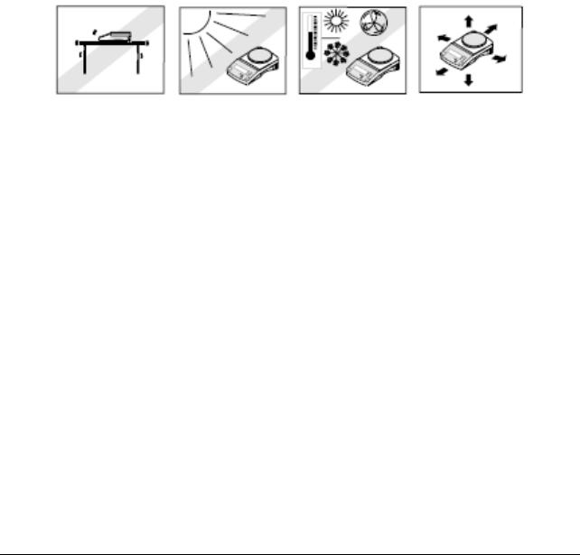
To service an indicator, the service area should meet the following requirements:
Must be protected from electrostatic discharge.
Should be temperature controlled and meet the indicator specifications for temperature environmental requirements. See specifications for temperature range.
Must be free of vibrations such as fork lift trucks close by, large motors, etc.
Must be free of air currents or drafts from air conditioning/heating ducts, open windows, people walking by, fans, etc.
Area must be clean and air must not contain excessive dust particles.
Work surface must be stable and level.
Work surface must not be exposed to direct sunlight or radiating heat sources.
1.3 TOOLS AND TEST EQUIPMENT REQUIRED
In order to properly service the Indicator, certain special tools and test items are required in addition to standard electronic tool kits. These items are listed as follows:
1.3.1Special Tools and Test Equipment List
1.Ohaus Scale Base.
2.Load Cell Simulator optional.
3.Computer with RS232 Interface for testing the RS232 communications.
4.RS232 Interface cable.
5.Data Printer for use with RS232 communications.
6.ESD work station or mat.
Ohaus Corporation www.ohaus.com |
2 |
Defender 5000 Indicators Service Manual |
1.3.2Standard Tools and Test Equipment List
1.Standard Electronics Tool Kit
2.Digital Voltmeter (DVM), with clip on probes. Input impedance of at least 10 megohms in the 1 Volt dc position.
3.Soldering Iron, solder and flux remover.
1.4 OVERVIEW OF PARTS AND CONTROLS
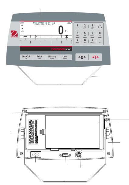
1.4.1 TD52P
1
|
|
|
|
|
|
TABLE 1-1 TD52P PARTS |
|
|
|
|
2 |
|
|
|
|
|
|
|
|
Item |
Description |
||
|
|
|
|
||||
|
|
|
|
|
3 |
1 |
Data Label |
|
|
|
|
|
2 |
Front Housing |
|
|
|
|
|
|
|||
|
|
|
|
|
|
||
|
|
|
|
|
|
3 |
Control Panel |
|
|
|
|
|
|
4 |
Mounting Bracket |
|
|
|
|
|
|
5 |
Screw (4) |
|
|
|
|
|
|
6 |
Adjusting Knob (2) |
|
|
|
|
|
|
7 |
Security Screw |
|
|
|
|
|
|
8 |
Accessory Cover |
|
|
|
|
|
|
9 |
Rear Housing |
|
|
|
|
|
|
10 |
Power Connector |
|
|
|
|
|
|
11 |
RS232 Connector |
|
4 |
|
|
|
|
||
|
|
|
|
|
12 |
Load Cell Connector |
|
|
|
|
|
|
|
|
|
5
7
8
6
9
10 |
|
|
|
|
|
11 |
|
|
|
|
|
12 |
||
|
|
|
||
|
||||
|
|
|
|
|
|
|
|
|
|
Figure 1-1 |
TD52P Indicator |
|
|
|
|
|
|
Ohaus Corporation www.ohaus.com |
3 |
Defender 5000 Indicators Service Manual |
|
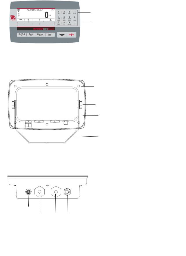
1.4.2 TD52XW
|
TABLE 1-2 TD52XW PARTS |
|
|
|
|
|
Item |
Description |
|
1 |
Control Panel |
|
2 |
Front Housing |
|
3 |
Screw (6) |
1 |
4 |
Adjusting knob (2) |
|
5 |
Rear Housing |
2 |
6 |
Mounting Bracket |
|
7 |
Load Cell Connector |
|
8 |
Strain Relief for Option |
|
9 |
Power Cord |
|
10 |
Strain Relief for Option |
3
4
5
6
7
8 10 9
Figure 1-2 TD52XW Indicator
Ohaus Corporation www.ohaus.com |
4 |
Defender 5000 Indicators Service Manual |
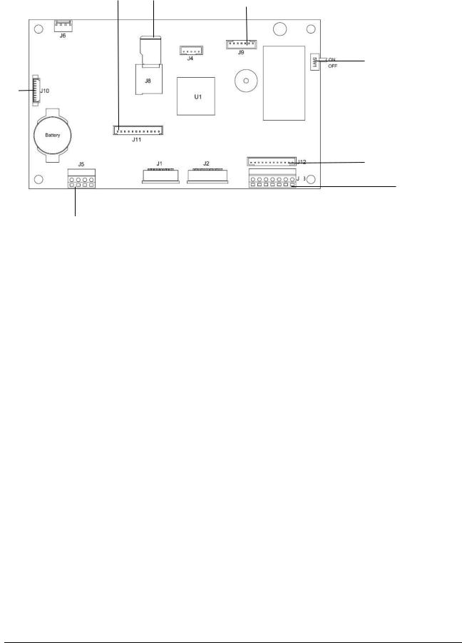
1.4.3 MAIN PC BOARD
1 |
2 |
3 |
|
|
|
5
4
6
8
7
|
Figure 1-3 Main PC Board |
|
TABLE 1-3 MAIN PC BOARD |
|
|
Item |
Description |
1 |
IO/Analog/RS232-RS485-USB Device (J11) |
2 |
SD Card (J8) |
3 |
Rechargeable Battery Pack (J9) |
4 |
USB Host/Ethernet (J4) |
5 |
Security Switch (SW1) |
6 |
Load Cell (J12) |
7 |
RS232 (J5) |
8 |
Load Cell (J3) |
Ohaus Corporation www.ohaus.com |
5 |
Defender 5000 Indicators Service Manual |
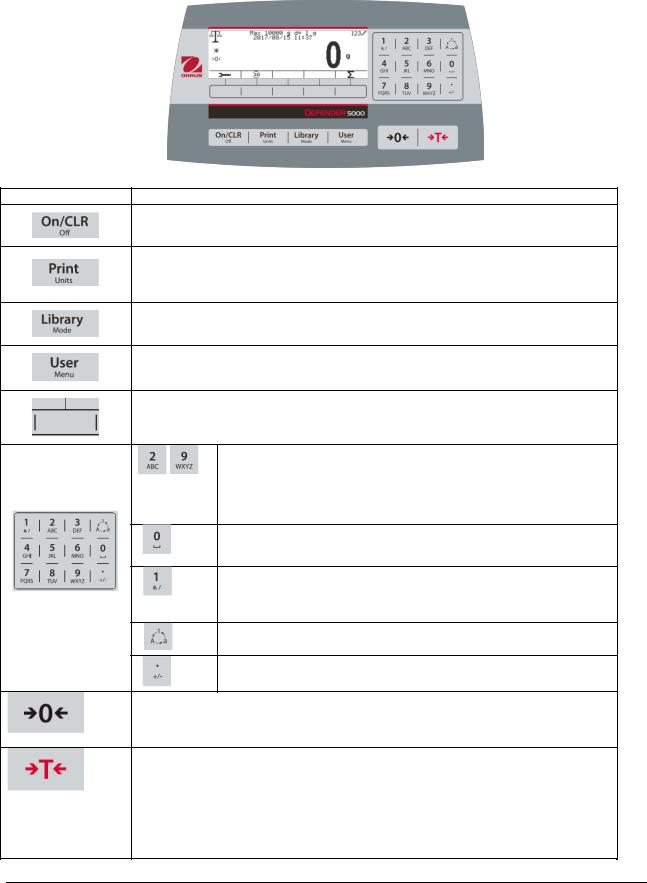
1.5 CONTROL FUNCTIONS
Button Action
Short press: If the terminal is Off, power on the terminal; if the terminal is On, clear the data input.
Long press: Power off the terminal.
Short press: Send the current display value to RS232 port in the case where the "Communication -> RS232 setup->Assignment->Demand" is "On".
Long press: Change the current weighing unit. Press and hold the key to scroll through the list of enabled units. Release the key to switch to the unit selected.
Short press: Press the key to enter the Library.
Long press: Press and hold this key to change weighing modes. Press and hold the key to scroll through all weighing modes. Release the key to switch to the mode selected.
Short press: Press the key to enter user profile.
Long press: Press the key to enter user menu.
The soft keys correspond to several icons at the bottom of the display area. These icons indicate configuration, ID input, accumulate, exit, etc. (available in certain circumstances).
To enter ‘2’-‘9’, press the numeric button in the mode of numeric input.
To Enter ‘A’, press  2 times in the mode of uppercase input. To enter ‘Z’, press
  5 times in the mode of lowercase input.
To enter ‘0’, press the button in the mode of numeric input. To enter a space, press the button in the mode of uppercase or lower case input.
To enter '1', press the button in the mode of numeric input. To enter '#' or '/', press the button in the mode of uppercase input. To enter '@', '_' or '&', press the button in the mode of lowercase input.
Switch between three input modes, namely, numeric, lowercase and uppercase input.
To enter '.', press the button in the mode of numeric input. To enter '+' or '-', press the button in he mode of uppercase or lowercase input.
Short press: When the load on the pan is within the zero range, press this key to set the display to zero.
Short press: When a tare has been entered and the load on the pan is within the zero range, press this key to clear the tare value and set the display to zero.
Short press: When a container is on the pan, press this key to store the weight of the container as the tare value.
Short press: Enter the known weight of a container using the numeric keypad, and then press this key to establish the preset tare value.
Short press: When a tare has been entered, empty the pan and press this key to clear the tare value.
Long press: If a preset tare has been entered, press this key to view the preset tare value.
Ohaus Corporation www.ohaus.com |
6 |
Defender 5000 Indicators Service Manual |
1.6 EXTERNAL CONNECTIONS
This section of the manual explains the external connection of the product.
1.6.1 Scale Base with Connector
Ohaus bases with a connector can be attached to the external load cell connector (Figure 1-1, item 12). To make the connection, plug the base connector onto the external load cell connector. Then rotate the base connector’s locking ring clockwise. Refer to section 1.7.2 for bases without a connector.
1.6.2 RS232 interface Cable to TD52P
Connect the optional RS232 cable to the RS232 connector (Figure 1-1, item 11).
|
Pin |
Connection |
|
1 |
N/C |
|
2 |
TXD |
|
3 |
RXD |
|
4 |
N/C |
|
5 |
GND |
|
6 |
N/C |
|
7 |
CTS |
|
8 |
RTS |
Figure 1-4 RS232 Pins |
9 |
N/C |
1.6.3 AC Power to TD52P
Connect the AC power cord (supplied) to the power receptacle (Figure 1-1, item 10), then connect the AC plug to an electrical outlet.
1.6.4 AC Power to TD52XW
Connect the AC plug to a properly grounded electrical outlet.
1.6.5 Battery Power
The indicator can be operated on a rechargeable battery pack (not supplied) when AC power is not available. It will automatically switch to battery operation if there is power
failure or the power cord is removed. The indicator can operate for up to 21 hours on battery power. During battery operation, the battery charge symbol indicates the battery status. The indicator will automatically turn-off when the batteries are fully discharged. Find detailed installation information in battery pack (P/N 30424405) operation manual.
1.7 Internal Connections
Some connections require the housing to be opened.
1.7.1 Opening the Housing
CAUTION: ELECTRICAL SHOCK HAZARD. REMOVE ALL POWER CONNECTIONS TO THE INDICATOR BEFORE SERVICING OR MAKING INTERNAL CONNECTIONS. THE HOUSING SHOULD ONLY BE OPENED BY AUTHORIZED AND QUALIFIED PERSONNEL, SUCH AS AN ELECTRICAL TECHNICIAN.
TD52P
Remove the four Phillips head screws from the rear housing.
Remove the front housing being careful not to disturb the internal connections.
Once all connections are made, reattach the front housing.
Ohaus Corporation www.ohaus.com |
7 |
Defender 5000 Indicators Service Manual |
TD52XW
Remove the four hex head screws from the rear housing. Open the housing by carefully pulling the front housing forward. Once all connections are made, reattach the front housing.
The screws should be tightened to 2.5 N•m (20-25 in-lb) torque to ensure a watertight seal.
1.7.2 Scale Base Without Connector
For connecting bases (which do not have the connector) to a TD52P or TD52XW, a cable gland kit (P/N 30379716) is available as an accessory.
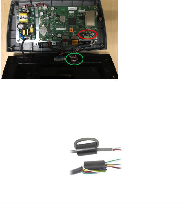
Removing the pre-installed Load Cell connector and wiring harness
Before doing the connections, remove the pre-installed Load Cell connector and wiring harness by following the steps below.
1.Open the housing by carefully pulling the front housing forward.
2.Unplug the white load cell connector from the main PCBA board (red circle).
3.Remove the metal terminal (Figure 1-1, item 12) connector from the rear housing.(green circle)
Installing Cables and Connectors
In order to meet certain electrical noise emission limits and to protect the TD52P and TD52XW from external influences, it is necessary to install a ferrite core on the load cell cable connected to the terminal. The ferrite core is included with the terminal.
To install the ferrite, simply route the cable through the center of the core and then take one wrap around the outside of the core and route the cable through the center again. Either the complete cable or the individual wires can be wrapped through the ferrite. This should be done as close to the enclosure as possible. See Figure 1-5.
Figure 1-5
Main Board Wiring Connections
Once the TD52P and TD52XW enclosure is open, connections can be made to the terminal strips on the main board, as shown in Figure 1-6.
Ohaus Corporation www.ohaus.com |
8 |
Defender 5000 Indicators Service Manual |

Figure 1-6
Jumper Connections
The TD52P and TD52XW terminals are designed to support both 2mV/V and 3mV/V load cells from the same circuitry. A load cell output rating selection jumper is not required.
Figure 1-7 shows the terminal definitions for the analog load cell terminal strip. Note that when using fourwire load cells, jumpers must be placed between the +Excitation and +Sense terminals and between the Excitation and Sense terminals.
Figure 1-7 Jumper Connections
After wiring is completed, replace the indicator housing screws. Make sure the liquid-tight connector is properly tightened.
Ohaus Corporation www.ohaus.com |
9 |
Defender 5000 Indicators Service Manual |
1.7.3 RS232 Interface Cable to TD52XW
Pass the optional RS232 cable through the strain relief (Figure 1-2, item 10) and attach it to terminal block J5 (Figure 1-3, item 7). Tighten the strain relief to maintain a watertight seal.
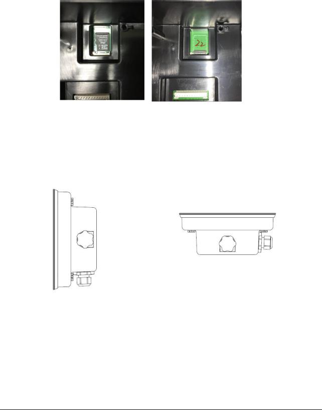
1.7.4 MICRO SD Card Installation
The SD memory card can be used for additional storage in the Checkweighing and Counting applications. Figure 1-8 shows the installation of an SD card into the socket on the edge of the TD52P andTD52XW main board.
Figure 1-8 Sliding an SD Card into the SD Socket (left); SD Card Installed (right)
1.8 TD52XW Rear Housing Orientation
The TD52XW is delivered in the wall mount orientation with the connections exiting below the display. The rear housing may be reversed so the connections exit above the display when the TD52XW is placed horizontally on a bench. To reverse the rear housing, remove the four Phillips head screws, carefully rotate the housing 180°, and reinstall the screws.
Figure 1-9 Wall Mount Configuration |
Figure 1-10 Bench Top Configuration |
1.9 Mounting Bracket
Attach the bracket to a wall or table using fasteners (not supplied) that are appropriate for the type of mounting surface. The bracket will accommodate up to 6 mm (1/4”) diameter screws. Locate the mounting holes as shown in Figure 1-11.
Ohaus Corporation www.ohaus.com |
10 |
Defender 5000 Indicators Service Manual |
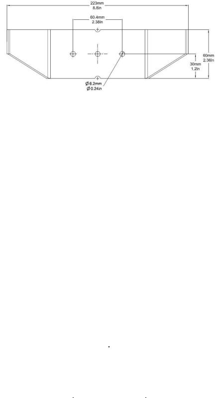
Figure 1-11 Mounting Bracket Dimensions
2 SETTINGS
This section of the manual explains the Menu Structure of the Indicator.
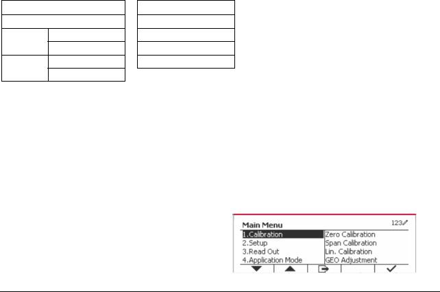
2.1Menu Structure
|
|
|
|
TABLE 2-1 MENU STRUCTURE |
|
|
||
|
|
|
|
|
|
|
|
|
Calibration |
|
Setup |
|
|
Read Out |
|
Application Mode |
|
|
|
|
|
|
|
|
|
|
Zero |
|
Capacity Unit |
|
|
Stability |
|
Weighing |
|
|
|
|
|
|
|
|
|
|
Span |
|
Range |
|
|
Zero Range |
|
Counting |
|
|
|
|
|
|
|
|
|
|
Linearity |
|
|
|
>|1|< Capacity |
|
Filter Level |
|
Check |
|
|
|
|
|
|
|
|
|
GEO |
|
Capacity & |
|
>|1|<Graduation |
|
Auto Zero Track |
|
Percent |
|
|
Graduation |
|
>|2|< Capacity |
|
Auto Dim |
|
Dynamic |
|
|
|
|
|
|
|
|
|
|
|
|
|
>|2|<Graduation |
|
Brightness |
|
Reset |
|
|
|
|
|
|
|
|
|
|
|
Language |
|
|
Screensaver |
|
|
|
|
|
|
|
|
|
|
||
|
|
Power On Zero |
|
Auto Off |
|
|
||
|
|
|
|
|
|
|
||
|
|
Power On Unit |
|
Base Auto Off |
|
|
||
|
|
|
|
|
|
|
|
|
|
|
Key Beep |
|
|
Adjust Contrast |
|
|
|
|
|
|
|
|
|
|
||
|
|
Transaction Counter |
|
Reset |
|
|
||
|
|
|
|
|
|
|
|
|
|
|
Next Transaction |
|
|
|
|
||
|
|
|
|
|
|
|
|
|
|
|
Password |
|
|
|
|
|
|
|
|
|
|
|
|
|
|
|
|
|
Reset |
|
|
|
|
|
|
|
|
|
|
|
|
|
|
|
|
|
|
|
|
|
|
|
|
|
Unit |
|
GMP |
|
Communication |
|
|
|
|
|
|
|
|
|
|
|
|
|
|
|
Gram(g) |
|
Date |
|
|
|
|
Baud Rate |
|
|
|
Format |
|
|
|
|
|
||
|
|
|
|
|
|
|
|
|
|
|
Kilogram(kg) |
|
Date |
|
|
|
|
Parity |
|
|
Pound(lb) |
|
Time |
|
|
|
|
Stop Bit |
|
|
|
Format |
|
|
|
|
|
||
|
|
|
|
|
|
|
|
|
|
|
Ounce(oz) |
|
Time |
|
RS232/ |
|
Configuration |
Handshake |
|
|
|
|
|
|
2ndRS232/USB |
|
|
|
|
|
Pound:Ounce |
|
Project ID |
|
|
|
Alt Print CMD |
|
|
|
|
|
Device* |
|
|
|
|||
|
(lb:oz) |
|
|
|
|
|
|||
|
|
|
|
|
|
|
|
||
|
|
|
|
|
|
|
|
|
|
|
Tonne(t) |
|
Scale ID |
|
|
|
|
Alt Tare CMD |
|
|
|
|
|
|
|
|
|
|
|
|
Ton(ton) |
|
Reset |
|
|
|
|
Alt Zero CMD |
|
|
|
|
|
|
|
|
|
|
|
|
Custom Unit |
|
|
|
|
|
|
Reset |
|
|
|
|
|
|
|
|
|
|
|
|
Unit Name |
|
|
|
|
|
Print Setup |
Assignment |
|
|
|
|
|
|
|
|
|
|
|
|
|
|
|
|
|
|
|
|
|
|
Ohaus Corporation www.ohaus.com |
11 |
Defender 5000 Indicators Service Manual |
|
|||||

|
Unit |
|
|
GMP |
|
Communication |
|
|
|
|
|
|
|
|
|
|
|
|
|
|
|
|
|
Factor |
|
|
|
|
|
Select Template |
|
|
|
|
|
|
|
|
|
|
|
|
|
|
|
Exponent |
|
|
|
|
|
Edit Template |
|
|
|
|
|
|
|
|
|
|
|
|
|
|
|
LSD |
|
|
|
|
|
Edit String |
|
|
|
|
|
|
|
|
|
|
|
|
|
|
Reset |
|
|
|
|
|
|
|
Reset |
|
|
|
|
|
|
|
|
|
|
|
|
|
|
|
|
|
|
|
|
|
Address |
|
|
|
|
|
|
|
|
|
|
|
|
|
|
|
|
|
|
|
|
|
Baud Rate |
|
|
|
|
|
|
|
|
|
|
|
|
|
|
|
|
|
|
|
|
|
Parity |
|
|
|
|
|
|
|
|
|
|
|
|
|
|
|
|
|
|
|
|
|
Stop Bit |
|
|
|
|
|
|
|
|
|
|
|
|
|
|
|
|
|
|
|
|
Configuration |
Handshake |
|
|
|
|
|
|
|
|
|
|
|
|
|
|
|
|
|
|
|
|
|
Alt Print CMD |
|
|
|
|
|
|
|
|
|
|
|
|
|
|
|
|
|
|
RS485* |
|
|
Alt Tare CMD |
|
|
|
|
|
|
|
|
|
|
|
|
|
|
|
|
|
|
|
|
Alt Zero CMD |
|
|
|
|
|
|
|
|
|
|
|
|
|
|
|
|
|
|
|
|
|
|
|
|
|
|
|
|
|
|
|
|
|
Reset |
|
|
|
|
|
|
|
|
|
|
|
|
|
|
|
|
|
|
|
|
|
Assignment |
|
|
|
|
|
|
|
|
|
|
|
|
|
|
|
|
|
|
|
|
|
Select Template |
|
|
|
|
|
|
|
|
|
|
|
|
|
|
|
|
|
|
|
|
Print Setup |
Edit Template |
|
|
|
|
|
|
|
|
|
|
|
|
|
|
|
|
|
|
|
|
|
Edit String |
|
|
|
|
|
|
|
|
|
|
|
|
|
|
|
|
|
|
|
|
|
Reset |
|
|
|
|
|
|
|
|
|
|
|
|
|
|
|
|
|
|
|
|
|
Host Name |
|
|
|
|
|
|
|
|
|
|
|
|
|
|
|
|
|
|
|
|
|
MAC Address |
|
|
|
|
|
|
|
|
|
|
|
|
|
|
|
|
|
|
|
|
|
Port |
|
|
|
|
|
|
|
|
|
|
|
|
|
|
|
|
|
|
|
|
|
Version |
|
|
|
|
|
|
|
|
|
|
|
|
|
|
|
|
|
|
|
|
|
DHCP |
|
|
|
|
|
|
|
|
|
|
|
|
|
|
|
|
|
|
|
|
|
IP Address |
|
|
|
|
|
|
|
|
|
|
|
|
|
|
|
|
|
|
|
|
Configuration |
Subnet Mask |
|
|
|
|
|
|
|
|
|
|
|
|
|
|
|
|
|
|
|
|
Gateway |
|
|
|
|
|
|
|
|
|
|
|
|
|
|
|
|
|
|
|
|
|
|
|
|
|
|
|
|
|
|
|
|
|
Primary DNS |
|
|
|
|
|
|
|
|
|
|
|
|
|
|
|
|
|
|
Ethernet* |
|
|
Secondary DNS |
|
|
|
|
|
|
|
|
|
|
|
|
|
|
|
|
|
|
|
|
|
Alt Print CMD |
|
|
|
|
|
|
|
|
|
|
|
|
|
|
|
|
|
|
|
|
|
Alt Tare CMD |
|
|
|
|
|
|
|
|
|
|
|
|
|
|
|
|
|
|
|
|
|
Alt Zero CMD |
|
|
|
|
|
|
|
|
|
|
|
|
|
|
|
|
|
|
|
|
|
Reset |
|
|
|
|
|
|
|
|
|
|
|
|
|
|
|
|
|
|
|
|
|
Assignment |
|
|
|
|
|
|
|
|
|
|
|
|
|
|
|
|
|
|
|
|
|
Select Template |
|
|
|
|
|
|
|
|
|
|
|
|
|
|
|
|
|
|
|
|
Print Setup |
Edit Template |
|
|
|
|
|
|
|
|
|
|
|
|
|
|
|
|
|
|
|
|
|
Edit String |
|
|
|
|
|
|
|
|
|
|
|
|
|
|
|
|
|
|
|
|
|
Reset |
|
|
|
|
|
|
|
|
|
|
|
|
|
|
|
|
|
|
|
|
|
MAC Address |
|
|
|
|
|
|
|
|
|
|
|
|
|
|
|
|
|
|
|
|
|
Search |
|
|
|
|
|
|
|
|
|
|
|
|
|
|
|
|
|
|
|
|
|
DHCP Client |
|
|
|
|
|
|
|
|
|
|
IP Address |
|
|
|
|
|
|
|
|
|
|
|
|
|
|
|
|
|
|
|
|
|
Subnet Mask |
|
|
|
|
|
|
|
|
|
|
|
|
|
|
|
|
|
|
Wifi* |
|
Configuration |
Gateway |
|
|
|
|
|
|
|
|
|
|
|
|
|
|
|
|
|
|
|
|
|
Port |
|
|
|
|
|
|
|
|
|
|
|
|
|
|
|
|
|
|
|
|
|
Alt Print CMD |
|
|
|
|
|
|
|
|
|
|
|
|
|
|
|
|
|
|
|
|
|
Alt Tare CMD |
|
|
|
|
|
|
|
|
|
|
|
|
|
|
|
|
|
|
|
|
|
Alt Zero CMD |
|
|
|
|
|
|
|
|
|
|
|
|
|
|
|
|
|
|
|
|
|
Reset |
|
|
|
|
|
|
|
|
|
|
|
|
|
|
|
|
|
|
|
|
|
|
|
|
Ohaus Corporation www.ohaus.com |
12 |
Defender 5000 Indicators Service Manual |
|
||||||
Unit |
|
GMP |
|
Communication |
|
|
|
|
|
|
|
|
|
|
|
|
|
|
|
Assignment |
|
|
|
|
|
|
|
|
|
|
|
|
|
Select Template |
|
|
|
|
|
|
|
|
|
|
|
|
Print Setup |
Edit Template |
|
|
|
|
|
|
|
|
|
|
|
|
|
Edit String |
|
|
|
|
|
|
|
|
|
|
|
|
|
Reset |
|
|
|
|
|
|
|
|
|
|
|
|
Device name |
OHBT_1 |
|
|
|
|
|
|
|
|
|
|
|
|
MAC Address |
00-11-22-33-44- |
|
|
|
|
|
55 |
|
|
|
|
|
|
|
|
|
|
|
|
|
Search Device |
|
|
|
|
|
Bluetooth* |
|
|
|
|
|
|
|
Device name |
|
|
|
|
|
|
|
|
|
|
|
|
|
|
|
|
|
|
|
|
BT Base Info |
MAC Address |
|
|
|
|
|
|
|
|
|
|
|
|
LFT |
|
|
|
|
|
|
|
|
|
|
|
|
|
|
|
|
|
|
|
|
|
Battery |
|
|
|
|
|
|
|
|
|
|
|
|
|
None, Displayed |
|
|
|
|
|
|
Weight, ABS- |
|
|
|
|
|
Source |
Displayed |
|
|
|
|
|
|
Weight, Gross |
|
|
|
|
|
|
Weight |
|
|
|
|
|
Output Type |
4-20mA, 0-10V |
|
|
|
|
|
|
|
|
|
|
|
|
|
0(any valid value |
|
|
|
|
Analog* |
Zero Value |
below the high |
|
|
|
|
|
|
limit) |
|
|
|
|
|
|
Desired source |
|
|
|
|
|
Full Scale Value |
value, scale |
|
|
|
|
|
|
capacity |
|
|
|
|
|
Cal Output Zero |
|
|
|
|
|
|
|
|
|
|
|
|
|
Cal Output Full |
|
|
|
|
|
|
|
|
SD Card
Library
Mode
Memory
Link to
User
Mode
User Profiles
Maintenance
Export Menu
Import Menu
Diagnosis
Service Menu
* Submenu for options will be active only when the specific board is installed.
The Bluetooth® word mark and logos are registered trademarks owned by Bluetooth SIG, Inc. and any use of such marks by OHAUS is under license.
2.2 Menu Navigation
To enter the Main Menu, press the button  from any application home screen.
Ohaus Corporation www.ohaus.com |
13 |
Defender 5000 Indicators Service Manual |
 Loading...