


TD52

折ↅ
∎䞷広㢝
Interfaz E/S Discreta
Manual de instrucciones
Interface discrète I/O
Manuel d’instruction
Discrete I/O-Schnittstelle
Bedienungsanleitung
Modulo d’Interfaccia I/O
TD52 Indicator
Discrete I/O Option
Instruction Manual
Manuale di Istruzioni
I/O 折

EN-1
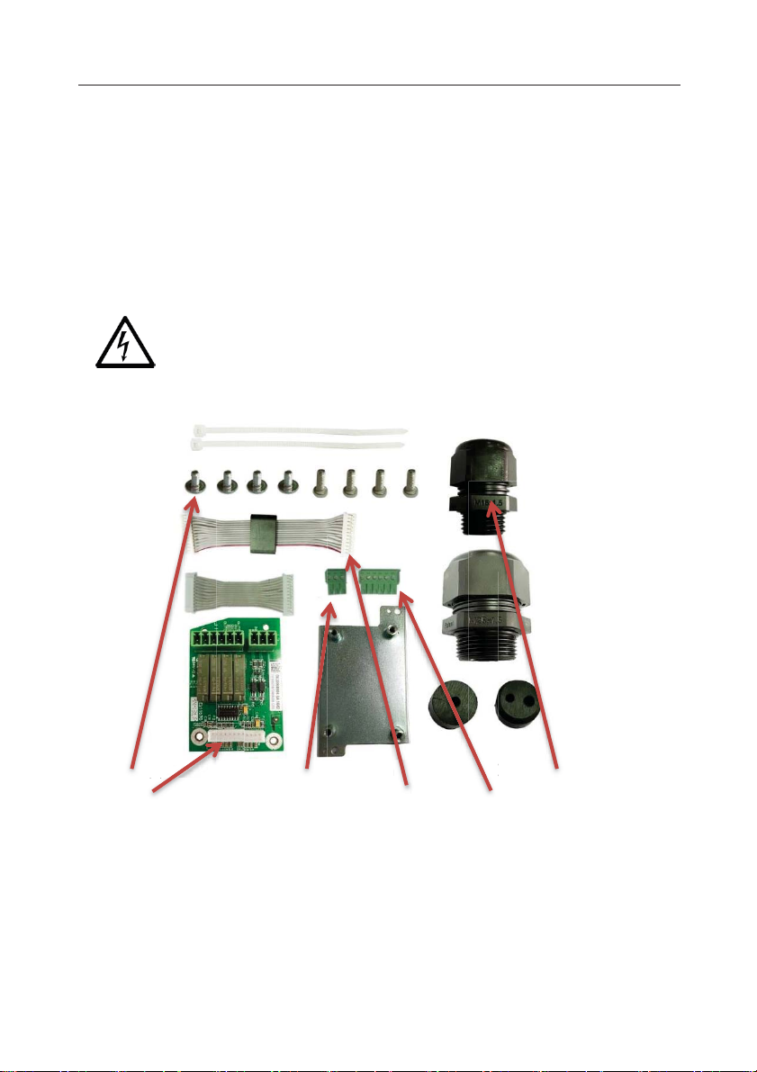
CAUTION: Read all safety warnings before installing, making connections, or servicing the
Discrete I/O PCB. Failure to comply with these warnings could result in personal injury
and/or property damage. Retain all instructions for future reference.
Screws (4)
Connector, 3 Pin
Cable Gland
I/O PCB
Cable to mainboard
Connector, 6 Pin
()
board
C
d
C
)
ector, 3 P
o
n
INTRODUCTION
This discrete I/O interface Kit is for use with OHAUS TD52P and TD52XW indicators.
When installed, the system software allows the relay to be programmed in a variety of ways.
BASIC APPLICATIONS
Applications include driving external Over/Accept/Under displays, motor controls for semi-automatic
filling systems, sorting systems, interfacing to industrial PLC systems, etc. The Relay outputs can also
be used as slave relays to drive high power relays in larger systems.
For the setup in each application, please refer to the instruction manual supplied with scale.
Set up the discrete I/O controls as described in the I/O menu section of that manual.
KIT CONTENTS
ws(4
ect
i
able Glan

EN-2
CAUTION: THE INSTALLATION AND WIRE CONNECTIONS TO THE DISCRETE I/O
PERSONNEL, SUCH AS AN ELECTRICIAN.
WARNING: BEFORE MAKING CONNECTIONS TO THE RELAY TERMINALS,
CONNECTIONS.
WARNING: WHEN MAKING ANY LINE VOLTAGE CONNECTIONS TO THE
Rib
Load cell cable male connector
Interface option cover
INTERFACE INSTALLATION
BOARD SHOULD ONLY BE DONE BY AUTHORIZED AND QUALIFIED
POWER OFF THE SYSTEM AND REMOVE ALL EXTERNAL AC POWER
DISCRETE I/O, FOLLOW NATIONAL ELECTRICAL CODE (NEC) OR LOCAL
AUTHORITY WIRING STANDARDS AND SAFETY PRACTICES.
For TD52P:
1. Separate the indicator from the base by loosening load cell cable male connector.
Remove the interface option cover.
2. Break off the rib of the accessory cover as shown.

EN-3
Cable
Ferrite
Main board
connector 2
12 Pin Connector
Screw
3. Connect the cable to the main board connector 2 as shown. Place the ferrite in the slot of
the rear housing as shown.
4. Install the relay board. Secure it with the 2 screws. Connect the cable to the relay board
12 pin connector.

EN-4
3 Pin / 6 Pin Connector
Nylon cable ties
Relay Cable
Screw
Load cell cable male
M25 Hole plug
5. Connect the relay cable to the 3 pin and 6 pin connectors. Fix the relay cable with the
nylon cable tie to avoid falling off from the terminal block.
6. Put the interface option cover back on the terminal.
For TD52XW:
1. Remove the interface option cover. Remove the 6 screws with sealed washers. Remove
the M25 hole plug as shown.
connector

EN-5
cable
Ferrite
Main board connector 2
2. Rotate the rear housing down a way from the front housing as shown.
3. Connect the cable to the main board connector 2. Place the ferrite in the slot of the
internal cover as shown.
EN-6
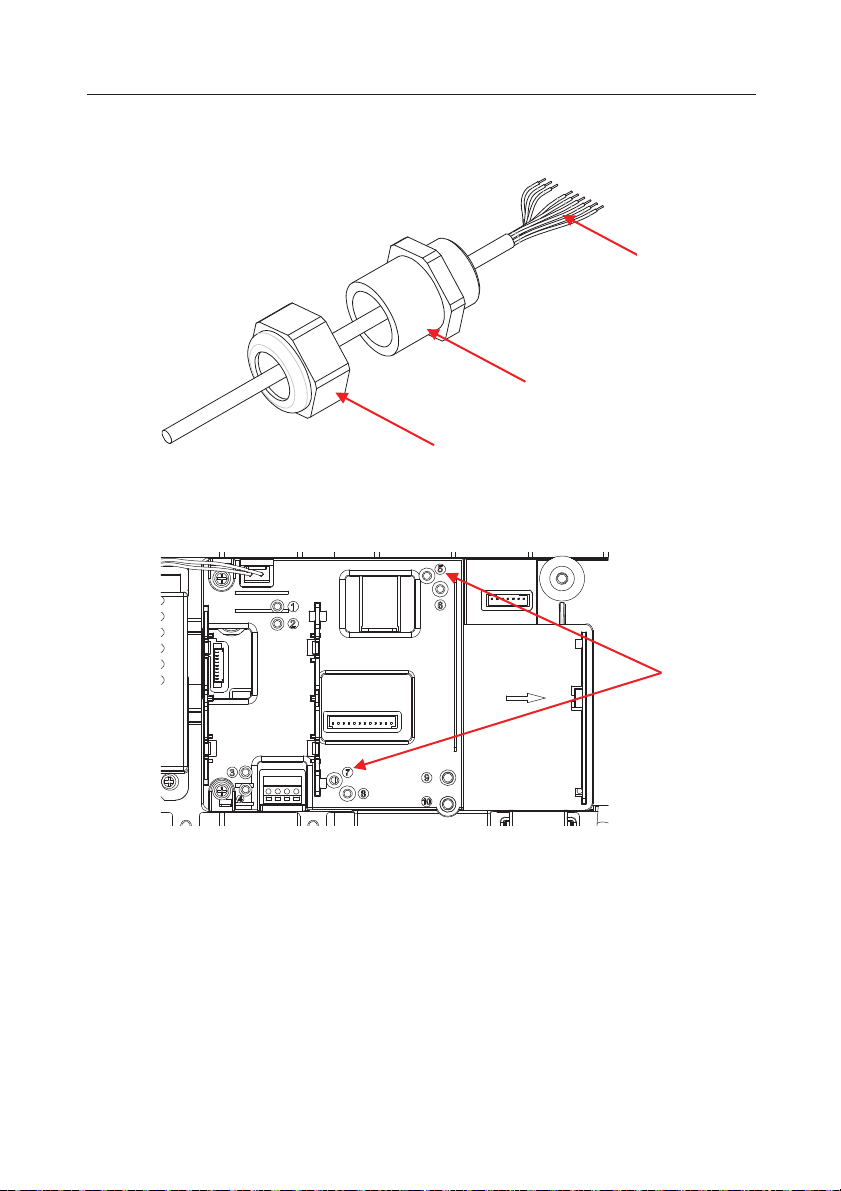
Relay Output Cable
M25 Gland
Cap Nut
Boss Post 5, 7
4. Disassemble the cable gland by loosening the cap nut and removing the rubber seal.
Pass the relay output through the cap nut, then spread the rubber seal and place it over
the cable. Now pass the cable through the body of the cable gland.
5. Install the relay board. Secure it with 2 screws. (Note: boss post is 5 and 7.)
Connect the cable to the relay board 12 pin connectors. Put the relay cable through the
M25 hole. Connect it to the 3 pin and 6 pin connectors.

EN-7
Screw
12Pin
Connector
3Pin / 6pin
Connector
Relay cable
Relay cable
M25 Gland
6. Put the rear housing back on the front housing. Re-install the 6 screws.
7. Fasten the M25 gland to the rear housing.

EN-8
Rubber Seal
Cap nut of M25 gland
Screw
M25 hole plug
Load cell cable male connector
8. Push the rubber seal into the M25 cable gland.
9. Fasten the cap nut of M25 gland.
For TD52XW with reversed rear cover:
1. Remove the interface option cover. Remove the 6 screws with sealed washer. Remove
the M25 hole plug as shown.

EN-9
Cable
Main board connector 2
Boss post 6,8
2. Take the rear housing down from the front housing as shown.
3. Connect the cable to the main board connector 2.
4. Install the relay board. Secure the relay board with 2 screws (Note: the boss post is 6, 8).
Connect the cable to the relay board 12 pin connector (Note: the ferrite needs to be
positioned nearby the accessory board 12 pin connector).

EN-10
12 Pin connector
Ferrite
Screw
Relay output
M25 Gland
Cap nut
Relay cable
3 Pin / 6 Pin Connector
5. Disassemble the cable gland by loosening the cap nut and removing the rubber seal.
Pass the relay output through the cap nut, then spread the rubber seal and place it over
the cable. Now pass the cable through the body of the cable gland.
6. Put the relay cable through the M25 hole. Connect it to the 3 pin and 6 pin connectors.

EN-11
Relay cable
M25 Gland
Rubber Seal
Cap nut of M25 gland
7. Put the rear housing back on the front housing. Re-install the 6 screws.
8. Fasten the M25 gland to the rear housing.
9. Push the rubber seal into the M25 cable gland.
10. Fasten the cap nut of the M25 gland.
EN-12
Notes:
CONNECTION
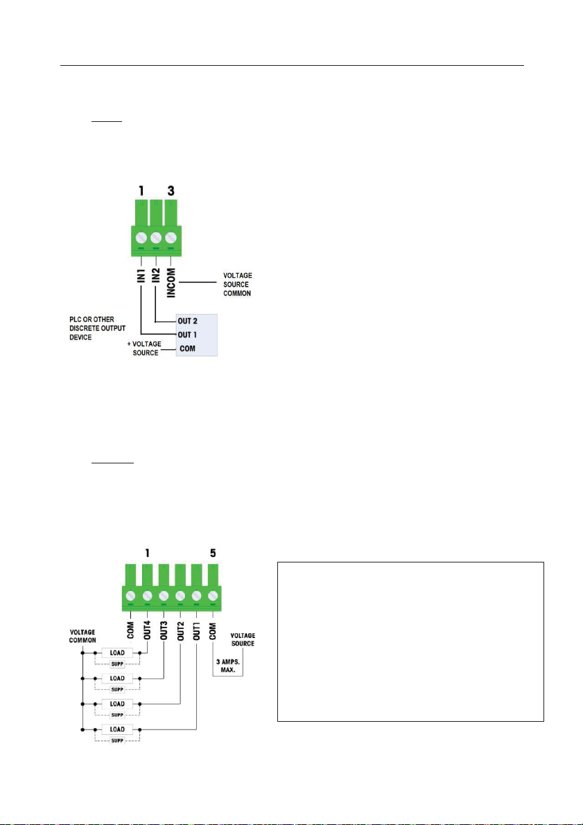
x INPUT
The discrete I/O interface enables other devices such as PLCs to provide the trigger voltage (typically
12 VDC or 24 VDC, maximum 30 VDC) to turn the inputs “on”.
An example of wiring to the inputs with the +V to the common is shown:
Note:
1. Voltage: 5~30 VDC, 10 mA maximum current. Voltage polarity cannot be reversed.
2. Do not bundle input wiring with power wiring or any other high energy cables.
3. Wire size: 18 AWG (0.832 mm
24 AWG (0.205 mm
x OUTPUT
The four dry-contact normally open relay outputs can switch up to 250 VAC or 30 VDC voltages at 1A
maximum.
The relay outputs are not polarity-sensitive since they are dry contact outputs.
An example of wiring to the outputs is given below:
2
) maximum
2
) minimum
1. Dry contact relays.
2. Relay contact rating:
AC: 24-250 VAC, 1.0 AMP. INTO resistive load.
DC: 5-45 VDC ,1.0 AMP. INTO resistive load.
Maximum switching power: 250VA, 30 W.
3. Maximum output circuit current = 3 AMPS.
4. All inductive loads must be suppressed.
5. Wire size: 18 AWG (0.832 mm
24 AWG (0.205 mm
2
) Maximum
2
) Minimum

EN-13
Mark
Standard
2014/30/EU (EMC). The EU Declaration of
Disposal
In conformance with the European Directive 2012/19/EU on Waste Electrical and
Electronic Equipment (WEEE) this device may not be disposed of in domestic waste.
This also applies to countries outside the EU, per their specific requirements.
Please dispose
point specified for electrical and electronic equipment. If you have any questions,
please contact the responsible authority or the distributor from which you purchased
this device.
Should this device be passed on to other parties (for private or professional use), the
content of this regulation must also be related.
For disposal instructions in Europe, refer to www.ohaus.com/weee.
Thank you for your contribution to environmental protection.
COMPLIANCE
This product complies with the applicable harmonized standards of EU
Directives 2011/65/EU (RoHS) and
Conformity is available online at www.ohaus.com/ce.
FCC Note
This equipment has been tested and found to comply with the limits for a Class A digital device,
pursuant to Part 15 of the FCC Rules. These limits are designed to provide reasonable protection
against harmful interference when the equipment is operated in a commercial environment. This
equipment generates, uses, and can radiate radio frequency energy and, if not installed and used in
accordance with the instructio n manual, may cause harmful interference to radio communications.
Operation of this equipment in a residential area is likely to cause harmful inte rference in which case
the user will be required to correct the interference at his own expense.
Industry Canada Note
This Class A digital apparatus complies with Canadian ICES-003.
of this product in accordance with local regulations at the collecting

ES-1
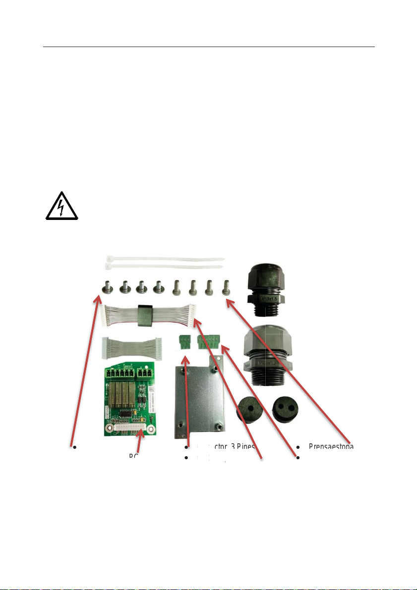
PRECAUCIÓN: leer todas las advertencias de seguridad antes de instalar, hacer
Conserve todas las instrucciones para futura referencia.
x Tornillos (4)
x Conector, 3 Pines
x Prensaestopas
x E/S placa de PC
x Cable a placa base
x Conector, 6 Pines
Con
Cable a placa base
pl
aca base
T
s
INTRODUCCIÓN
Este kit de interfaz E/S discreta se utiliza con los Indicadores Ohaus TD52P y TD52XW.
Una vez instalado, el software del sistema permite que el relé se programe en una variedad de maneras.
APLICACIONES BÁSICAS
Las aplicaciones incluyen pantallas «Under/Accept/Over» (por debajo/aceptar/por encima), controles
de motores para sistemas de llenado semi-automáticos, sistemas de clasificación, interconexión con
los sistemas PLC industriales, etc. Las salidas de relé también se pueden utilizar como relés
esclavos para accionar relés de alta potencia en sistemas más grandes.
Para la configuración de cada aplicación, consultar el manual de instrucciones suministrado con la
báscula.
Configurar los controles de E/S discreta como se describe en la sección del menú E/S del manual.
conexiones o realizar el mantenimiento de la E/S discreta del PCB. El incumplimiento
de las instrucciones podría resultar en lesiones personales y/o daños materiales.
CONTENIDO DEL KIT
ornillo

ES-2
PRECAUCIÓN: LA INSTALACIÓN Y CONEXIONES DE CABLEADO A LA PLACA
Y AUTORIZADO, COMO POR EJEMPLO UN ELECTRICISTA.
ADVERTENCIA: ANTES DE REALIZAR CONEXIONES A LOS TERMINALES DE
EXTERNAS.
ADVERTENCIA: AL REALIZAR CUALQUIER CONEXIÓN DE VOLTAJE DE LÍNEA A
ELÉCTRICAS Y PRÁCTICAS DE SEGURIDAD.
conector macho del cable de la
Cubierta de opciones de interfaz
Costilla
INSTALACIÓN DE INTERFAZ
E/S DISCRETA SOLO DEBEN SER REALIZADAS POR PERSONAL CUALIFICADO
RELÉ, APAGUE EL SISTEMA Y ELIMINE TODAS LAS CONEXIONES ELÉCTRICAS
LA E/S DISCRETA, SIGA LOS CÓDIGOS ELÉCTRICOS NACIONALES (NEC) O
ESTÁNDARES DE LAS AUTORIDADES LOCALES PARA INSTALACIONES
Para TD52P:
1. Separe el indicador de la base aflojando el conector del cable macho para la celda de
carga. Retire la cubierta de la interfaz.
celda de carga
2.
Cortar la lengüeta de la cubierta de accesorios, como se muestra.

ES-3
Ferrito
Conector de la
placa principal2
Cable
Conector de 12 pines
empulgueras
3. Conectar el cable al conector 2 de la placa principal como se muestra. Colocar la ferrita
en la ranura de la carcasa trasera, como se muestra.
4. Instalar la placa de relé. Fijarla por mediación de los 2 tornillos. Conectar el cable al
conector de la placa de relé de 12 pines.

ES-4
Conector de 3 pines / 6
Brida de nylon
Cable de
empulgueras
conector macho del
carga
Tapón de orificio
M25
5. Conectar el cable de relé a los conectores de 3 y 6 pines. Fijar el cable de relé con la
brida de nailon.
pines
relé
6. Colocar la cubierta de la interfaz de nuevo en el dispositivo.
Para TD52XW:
1. Retirar la cubierta de la interfaz. Quitar los 6 tornillos con las arandelas de sellado. Retirar
el tapón M25, como se muestra.
cable de la celda de

2. Separar la carcasa trasera de la carcasa frontal como se muestra.
cable
Ferrito
Conector de la placa
ES-5
3. Conectar el cable al conector 2 de la placa principal. Colocar la ferrita en la ranura de la
cubierta interna, como se muestra.
principal2

ES-6
Salida de relé
Ghiandola M25
tuerca ciega
Publicación de
4. Desmontar el prensaestopas aflojando la tuerca ciega y retirando la junta de goma. Pasar
la salida de relé a través de la tuerca ciega, después extender la junta de goma y
colocarla sobre el cable. A continuación, pasar el cable a través del prensaestopas.
5. Instalar la placa de relé. Fijarla por mediación de los 2 tornillos. (Nota: los puntos
principales de fijación son 5 y 7).
Conectar el cable al conector de la placa de relé de 12 pines. Introducir el cable de relé en
el orificio M25. Conectarlo a los conectores de 3 y 6 pines.
jefe5,7

ES-7
tornillo
Conector
de 12 pines
Conector de 3
pines / 6 pines
Cable de
relé
Cable de relé
Ghiandola M25
6. Colocar nuevamente la carcasa trasera en la carcasa frontal. Colocar los 6 tornillos.
7. Fijar el prensaestopas M25 a la carcasa trasera.

ES-8
Junta de goma
tuerca de casquillo de
la glándula M25
tornillo
Tapón de orificio M25
Conector hembra del cable de la
celda de carga
8. Empujar la junta de goma en el prensaestopas M25.
9. Fijar la tuerca ciega del prensaestopas M25.
Para el TD52XW con cubierta trasera invertida:
1. Retirar la cubierta de la interfaz. Quitar los 6 tornillos con las arandelas de sellado. Retirar
el tapón M25, como se muestra.

2. Separar la carcasa trasera de la carcasa frontal como se muestra.
Cable
Conector de la placa
principal2
Publicación de jefe6,8
3. Conectar el cable al conector 2 de la placa principal.
ES-9
4. Instalar la placa de relé. Fijar la placa de relé por mediación de 2 tornillos (Nota: los
puntos principales son 6 y 8). Conectar el cable al conector de 12 pines de la placa de
relé (Nota: la ferrita debe colocarse cerca del conector de 12 pines de la placa de
accesorios).

ES-10
Conector de 12 pines
Ferrito
tornillo
Salida de relé
Ghiandola M25
tuerca ciega
5. Desmontar el prensaestopas aflojando la tuerca ciega y retirando la junta de goma. Pasar
la salida de relé a través de la tuerca ciega, después extender la junta de goma y
colocarla sobre el cable. A continuación, pasar el cable a través del prensaestopas.

ES-11
Cable de relé
Conector de 3 pines / 6
pines
Cable de relé
Ghiandola M25
6. Introducir el cable de relé en el orificio M25. Conectarlo a los conectores de 3 y 6 pines.
7. Colocar nuevamente la carcasa trasera en la carcasa frontal. Colocar los 6 tornillos.
8. Fijar el prensaestopas M25 a la carcasa trasera.
 Loading...