


Adventurer Pro Balances
Instruction Manual

Compliance
Compliance to the following standards is indicated by the corresponding mark on the product.
Marking Standard
This product conforms to the EMC directive 2004/108/EC, the Low Voltage Directive 2006/95/EC and the Non-automatic Weighing Instruments Directive 90/384/EEC. The complete declaration of Conformity is available from Ohaus Corporation.
AS/NZS4251.1, AS/NZS4252.1
CAN/CSA-C22.2 No. 1010.1-92; UL Std. No. 61010A-1
EC Emissions Note
This device complies with EN55011/CISPR 11 Class B Group 1.
Important notice for verified weighing instruments
Weighing instruments verified at the place of manufacture bear one of the preceding marks on the packing label and the green ‘M’ (metrology) sticker on the descriptive plate. They may be put into service immediately.
Weighing instruments to be verified in two stages have no green ‘M’ (metrology) on the descriptive plate and bear one of the preceding identification marks on the packing label. The second stage of the initial verification must be carried out by the approved service organization of the authorized representative within the EC or by the national weights and measures (W+M) authorities.
The first stage of the initial verification has been carried out at the manufacturer’s work. It comprises all tests according to the adopted European standard EN45501:1992, paragraph 8.2.2.
If national regulations limit the validity period of the verification, the user of the weighing instrument must strictly observe the re-verification period and inform the respective W+M authorities.
Disposal
In conformance with the European Directive 2002/96 EC on Waste Electrical and Electronic Equipment (WEEE) this device may not be disposed of in domestic waste. This also applies to countries outside the EU, per their specific requirements.
Please dispose of this product in accordance with local regulations at the collecting point specified for electrical and electronic equipment.
If you have any questions, please contact the responsible authority or the distributor from which you purchased this device.
Should this device be passed on to other parties (for private or professional use), the content of this regulation must also be related.
For disposal instructions in Europe, refer to www.ohaus.com/weee. Thank you for your contribution to environmental protection.
FCC Note
This equipment has been tested and found to comply with the limits for a Class A digital device, pursuant to Part 15 of the FCC Rules. These limits are designed to provide reasonable protection against harmful interference when the equipment is operated in a commercial environment. This equipment generates, uses, and can radiate radio frequency energy and, if not installed and used in accordance with the instruction manual, may cause harmful interference to radio communications. Operation of this equipment in a residential area is likely to cause harmful interference in which case the user will be required to correct the interference at his own expense.
Industry Canada Note
This Class A digital apparatus complies with Canadian ICES-003.
Cet appareil numérique de la classe A est conforme à la norme NMB-003 du Canada.
ISO 9001 Registration
In 1994 Ohaus Corporation, USA, was awarded a certificate of registration to ISO 9001 by Bureau Veritus Quality International (VQI), confirming that the Ohaus quality
management system is compliant with the ISO 9001 standard’s requirements. On May 15, 2003, Ohaus Corporation, USA, was re-registered to the ISO 9001:2000 standard.

Adventurer Pro EN-1
|
|
TABLE OF CONTENTS |
|
1. |
INTRODUCTION ......................................................................................... |
EN-3 |
|
1.1 |
Description ............................................................................................... |
EN-3 |
|
1.2 |
Features |
................................................................................................... |
EN-3 |
1.3 |
Safety Precautions ..................................................................................... |
EN-3 |
|
2. |
INSTALLATION ........................................................................................... |
EN-4 |
|
2.1 |
Unpacking ................................................................................................ |
EN-4 |
|
2.2 |
Installing Components ............................................................................... |
EN-4 |
|
|
2.2.1 Assembly of Models AV412, AV812, AV2101, AV2102, AV3102, |
|
|
|
|
AV4101, AV4102, AV8101 ............................................................. |
EN-4 |
|
2.2.2 Assembly of Models AV64, AV114, AV213, AV264, AV313, AV413, |
|
|
|
|
AV513 ......................................................................................... |
EN-5 |
|
2.2.3 Assembly of Model AV53 ............................................................... |
EN-8 |
|
|
2.2.4 Assembly of Models AV212............................................................ |
EN-9 |
|
2.3. |
Selecting the Location ................................................................................ |
EN-9 |
|
2.4 |
Leveling the Balance .................................................................................. |
EN-9 |
|
2.5 |
Connecting Power ................................................................................... |
EN-10 |
|
|
2.5.1 |
AC Adapter.................................................................................. |
EN-10 |
|
2.5.2 |
Battery Installation ....................................................................... |
EN-10 |
|
2.5.3 Turning Power On and Off ............................................................ |
EN-10 |
|
2.6 |
Initial Calibration ..................................................................................... |
EN-10 |
|
3. OPERATION ................................................................................................. |
EN-11 |
||
3.1 |
Overview of Controls & Display Functions .................................................... |
EN-11 |
|
3.1.1Models AV53, AV212, AV412, AV812, AV1502, AV2101,
|
AV4101, AV8101 ........................................................................ |
EN-11 |
3.1.2 Models AV64, AV64C, AV114, AV114C, AV212C, AV53C, AV213, |
|
|
|
AV213C, AV313C, AV264, AV264C, AV412C, AV413, AV413C, |
|
|
AV513C, AV812C, AV2101C, AV2102, AV2102C, AV3101C, |
|
|
AV3102, V4101C, AV4102, AV4102C, AV8101C .......................... |
EN-11 |
3.2 Button Control Functions .......................................................................... |
EN-13 |
|
3.3 Using the Button Control Functions ............................................................ |
EN-14 |
|
3.3.1 Setting the Balance to Zero ......................................................... |
EN-14 |
|
3.3.2 |
Taring ........................................................................................ |
EN-14 |
3.3.3 Changing Units of Measure .......................................................... |
EN-14 |
|
3.3.4 |
Changing Application modes ....................................................... |
EN-14 |
3.3.5 |
Printing Data .............................................................................. |
EN-14 |
3.4MenuEN-16
3.4.1 |
Menu Structure ............................................................................ |
EN-15 |
3.4.2 |
Menu Navigation ........................................................................ |
EN-16 |
3.4.3 |
Changing Settings ...................................................................... |
EN-16 |

EN-2 Adventurer Pro
TABLE OF CONTENTS (Cont.)
3.5 |
Application Modes ................................................................................... |
EN-17 |
|
|
3.5.1 |
Weighing ................................................................................... |
EN-17 |
|
3.5.2 |
Parts Counting ........................................................................... |
EN-17 |
|
3.5.3 |
Percent Weighing ........................................................................ |
EN-18 |
|
3.5.4 |
Check Weighing ......................................................................... |
EN-19 |
|
3.5.5 |
Animal Weighing ......................................................................... |
EN-20 |
|
3.5.6 |
Display Hold ............................................................................... |
EN-21 |
|
3.5.7 |
Totalize ...................................................................................... |
EN-22 |
3.6 |
Additional Features .................................................................................. |
EN-22 |
|
|
3.6.1 |
Weigh Below ............................................................................... |
EN-22 |
|
3.6.2 |
Battery Operation ......................................................................... |
EN-23 |
3.7 |
Balance Settings ..................................................................................... |
EN-24 |
|
|
3.7.1 |
Calibration .................................................................................. |
EN-24 |
|
3.7.2 |
Calibration Masses ..................................................................... |
EN-29 |
|
3.7.3 |
Setup ........................................................................................ |
EN-30 |
|
3.7.4 |
Readout ..................................................................................... |
EN-30 |
|
3.7.5 |
Mode ........................................................................................ |
EN-30 |
|
3.7.6 |
Unit ........................................................................................... |
EN-31 |
|
3.7.7 |
Print-1 and Print-2 ...................................................................... |
EN-31 |
|
3.7.8 |
RS232-1 and RS232-2 ............................................................... |
EN-32 |
|
3.7.9 |
GLP Data ................................................................................... |
EN-33 |
|
3.7.10 |
GLP Print .................................................................................... |
EN-34 |
|
3.7.11 |
Reset ......................................................................................... |
EN-34 |
|
3.7.12 Lockout ...................................................................................... |
EN-35 |
|
|
3.7.13 |
End ........................................................................................... |
EN-35 |
3.8 |
Legal for Trade (LFT) ................................................................................ |
EN-35 |
|
3.9 |
Sealing Access to the Balance Settings ....................................................... |
EN-36 |
|
3.10 |
Printing Data .......................................................................................... |
EN-36 |
|
4. MAINTENANCE .............................................................................................. |
EN-37 |
||
4.1 |
Calibration ............................................................................................. |
EN-37 |
|
4.2 |
Cleaning ................................................................................................ |
EN-37 |
|
4.3 |
Troubleshooting ...................................................................................... |
EN-37 |
|
4.4 |
Service Information .................................................................................. |
EN-38 |
|
4.5 |
Parts ..................................................................................................... |
|
EN-38 |
4.6 |
Accessories ............................................................................................. |
EN-39 |
|
5. TECHNICAL DATA ........................................................................................... |
EN-40 |
||
5.1 |
Drawings ................................................................................................ |
EN-41 |
|
5.2 |
Specifications ......................................................................................... |
EN-43 |
|
5.3 |
Capacity x Readability ............................................................................. |
EN-46 |
|
5.4 |
Communication ...................................................................................... |
EN-49 |
|
|
5.4.1 |
Commands ................................................................................. |
EN-49 |
|
5.4.2 |
Connections ................................................................................ |
EN-50 |
Limited Warranty ............................................................................................... |
EN-51 |
||

Adventurer Pro |
EN-3 |
1 INTRODUCTION
This manual contains installation, operation and maintenance instructions for the Ohaus Adventurer Pro balances. Please read the manual completely before using the balance.
1.1 Description
The Adventurer Pro balances are precision weighing instruments that will provide you with years of service if properly cared for. The Adventurer Pro balances are available in capacities from 51 grams to 8100 grams.
1.1.1 Model Name Designations
Example: AV214CDR
AV = Product family abbreviation Adventurer Pro 214 = 210g model with 0.0001g readability C = With internal calibration (INCAL)
D = Dual range model
R = 2nd interface installed (RS232) U = 2nd interface installed (USB)
1.2 Features
The Adventurer Pro balances include many standard features. These include:
•Battery* or AC Adapter operation (AC Adapter included)
•Weighing, Parts Counting, Percent Weighing, Check Weighing, Animal Weighing Display Hold and Totalize application modes.
•In-use cover
•RS232 interface
•Integral security bracket
•Weigh below hook
* Battery operation is only available on certain models.
The Adventurer Pro also offers several optional features
•Internal Calibration
•USB interface
•Second RS232 Interface
1.3Safety Precautions
Please follow these safety precautions:
•Verify that the input voltage printed on the AC Adapter matches the local AC power supply.
•Use the balance only in dry locations.
•Do not operate the balance in hostile environments.
•Do not drop loads on the platform.
•Do not place the balance upside down, without first installing the cone cover.
•Service should be performed only by authorized personnel.
3 page 3 to 8.pmd |
3 |
7/20/2009, 11:45 AM |

EN-4 |
Adventurer Pro |
2 INSTALLATION
2.1 Unpacking
Carefully remove your Adventurer Pro balance and each of its components from the package. Save the packaging to ensure safe storage and transport.
2.2 Installing Components
Use the illustrations and instructions below to identify and assemble your Adventurer Pro model with its components. All components must be installed before using the balance.
2.2.1 Assembly of Models AV412, AV812, AV2101, AV2102, AV3102, AV4101, AV4102, AV8101
Note: Assembly instructions also apply to models with the suffix C, CR, CU, R or U.
1.Insert the Sub-platform on the Mounting Cone located in the center of the balance. Align the Sub-platform so that it is fully seated on the cone.
2.Place the Weighing Pan on the Sub-platform.
3.For applicable Adventurer Pro models, place the Wind Ring over the pins located on the perimeter of the balance.
Weighing Pan
Sub-platform
Wind Ring (INCAL models)
Pin |
Mounting Cone |
3 page 3 to 8.pmd |
4 |
7/20/2009, 11:45 AM |

Adventurer Pro |
EN-5 |
2.2.2 Assembly of Models AV64, AV114, AV213, AV264, AV313, AV413, AV513C, AV53C
Note: Assembly instructions also apply to models with the suffix C, CR, CU, R or U.
1.Insert the Platform Assembly on the Mounting Cone in the center of the balance.
2.Carefully remove each of the five (5) glass Draft Shield sections from its packing. You will note that two (2) of these are plain, two (2) contain handles, and the other is set in a plastic frame. These sections or panels comprise the front and rear, side doors, and top (respectively) of the Draft Shield. The Draft Shield contains four (4) upright posts and two (2) cross-members which act as a framework for insertion of the panels.
3.Install the plain glass panels to form the front and rear of the Draft Shield.
•Select a plain glass panel and insert the bottom edge of the glass in the recessed slot in front of the balance, as shown.
•As you push the top edge of the glass panel toward the cross-member, reach inside the top of the framework and depress the small clip located under the cross-member.
•Press the glass panel into the framework until you feel the glass slip into place.
•Release the clip when the glass panel is fully inserted.
•Repeat these steps to install the other plain glass panel on the opposite side of the framework.
Clip Locations
Close-up of Clip
Platform Assembly
Glass Rear Panel
Mounting Cone
Recessed Slot
Glass Front
3 page 3 to 8.pmd |
5 |
7/20/2009, 11:45 AM |

EN-6 |
Adventurer Pro |
2.2.2 Assembly of Models AV64, AV114, AV213, AV264, AV313, AV413, AV513, AV53C (Cont.)
4. Install the glass doors in the sides of the Draft Shield framework.
Note: The glass doors must be inserted in the Draft Shield framework before inserting the top door; likewise, you must remove the top door before you remove the side doors.
•Hold and position each door so that the handle is near the front of the balance and the small notch on the bottom edge of the door is lined up with the tab that protrudes from the side of the balance housing (shown below).
•Insert the top edge of the glass door into the recessed area under the top crossmember of the Draft Shield framework.
•Slide the notch on the bottom edge over the tab and slip the door in place.
5.The door may now be opened by sliding it toward the back of the balance.
Left Door
Close-up of Tab
Right Door
Close-up of Notch
3 page 3 to 8.pmd |
6 |
7/20/2009, 11:45 AM |
Adventurer Pro |
EN-7 |
2.2.2Assembly of Models AV64, AV114, AV213, AV264, AV313, AV413, AV513C, AV53C (Cont.)
6.Install the top door panel.
•Insert the top door in the Draft Shield by holding the door vertically over the top of the Draft Shield framework, as shown.
•Position the back edge of the door so that it lines up with two small hinges located on the rear cross-member.
•Gently press the door on to the hinges, until it snaps into place.
•Tilt the door forward to close.
Top Door
Close-up view of recessed hinge on
Draft Shield cross-member
3 page 3 to 8.pmd |
7 |
7/20/2009, 11:45 AM |

EN-8 |
Adventurer Pro |
2.2.3 Assembly of Model AV53
Note: Assembly instructions also apply to models with the suffix R or U.
1.Insert the Sub-platform on the mounting cone in the center of the balance.
2.Place the Weighing Pan on the Sub-platform.
3.Attach the Draft Shield by inserting the round bottom edge in the circular recessed slot, as shown.
4.Place the metal cover on top of the Draft Shield.
Draft Shield Cover
Round Edge
of Draft Shield
Weighing Pan
Sub-platform
Mounting Cone
Circular Recessed
Slot
3 page 3 to 8.pmd |
8 |
7/20/2009, 11:45 AM |

Adventurer Pro |
EN-9 |
|
|
2.2.4 Assembly of Models AV212
Note: Assembly instructions also apply to models with the suffix C, CR, CU, R or U.
1.Insert the Sub-platform on the Mounting Cone located in the center of the balance.
2.Place the Weighing Pan on the Sub-platform.
3.Place the Wind ring over the shoulder of the balance.
Weighing Pan
Sub-platform |
|
Wind ring |
Mounting Cone |
|
2.3 Selecting the Location
Locate the balance on a firm, steady surface. Avoid locations with excessive air current, vibrations, heat sources, or rapid temperature changes.
2.4 Leveling the Balance
Before the balance is used, the feet should be adjusted so that the scale is level with the surface. This will enable accurate weighing. You will see a level bubble indicator in a small round window on the front of the balance. Level the balance by adjusting the leveling feet so the bubble is centered in the circle, as seen below.
Balance Level
Untitled-1 |
9 |
6/23/2009, 11:49 AM |
EN-10 |
Adventurer Pro |
2.5 Connecting Power
2.5.1 AC Adapter
Connect the AC Adapter to the wall outlet. Connect the plug into the receptacle on the rear of the balance.
For use with CSA Certified (or equivalent approved) power source, which must have a limited circuit output.
2.5.2 Battery Installation
Some Adventurer Pro models operate with batteries. To install batteries, remove the pan and its components and install the cone cover to protect the load cell.
CAUTION:
To protect the balance from damage while installing batteries, make sure the cone cover is in place.
Remove the battery comparment cover from the bottom of the balance. Install 4 AA (LR6) batteries in the compartment, aligning the batteries according to the + and - symbols. With the balance in an upright position, remove the cone cover and re-install the pan and its components.
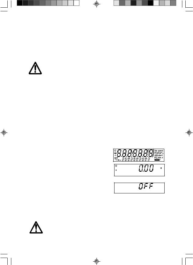
2.5.3 Turning Power On and Off
Press the On/Zero button to turn power on.
The balance performs a segment check. The balance then displays the last selected application mode.
To turn power off, press and hold the Off button until OFF is displayed, then release the button.
2.6 Initial Calibration
When the balance is first installed, and when it is moved to another location, it must be calibrated to ensure accurate weighing results. Have the appropriate calibration masses available before beginning calibration. Refer to Section 3.7.1 for masses and calibration procedure.
IMPORTANT:
Balance should acclimate to its new surroundings for at least 4 hours. Balance electronics should be warmed up for 1 hour prior to use.
Untitled-1 |
10 |
6/23/2009, 11:49 AM |

Adventurer Pro |
EN-11 |
|
|
3 OPERATION
3.1Overview of Controls & Display Functions
3.1.1Models AV53, AV212, AV412, AV812, AV2101, AV4101, AV8101
|
|
8 |
|
9 |
|
|
|
10 |
|
|
|
7 |
|
11 |
|
|
|
|
|
1 |
|
6 |
|
12 |
|
5 |
|
||
|
2 3 4 |
Top Views |
|
Bottom View |
|
|
|
||
|
|
14 |
|
17 |
|
|
|
13 |
|
|
|
|
Rear View |
18 |
|
|
|
|
3.1.2 Models AV64, AV64C, AV114, AV114C, AV212C, AV53C, AV213, AV213C, AV313, AV313C, AV264, AV264C, AV412C, AV413, AV413C, AV513C, AV812C, AV2101C, AV2102, AV2102C, AV3101C, AV3102, AV4101C, AV4102, AV4102C, AV8101C
|
8 |
|
|
15 |
7 |
10 |
|
|
|
||
|
|
16 |
|
|
6 |
9 |
|
|
12 |
||
1 |
5 |
||
|
|||
2 3 4 |
Top Views |
Bottom View |
|
|
|
16 |
|
|
17 |
18 |
|
|
14 |
13 |
Rear View
Untitled-1 |
11 |
6/23/2009, 11:49 AM |

EN-12 |
Adventurer Pro |
3.1 Overview of Controls and Display Functions (Cont.)
|
|
19 |
|
20 |
21 |
33 |
|
|
|
|
|
32 |
|
|
|
|
|
31 |
|
|
|
|
|
30 |
|
|
|
|
22 |
29 |
|
|
|
|
23 |
27 |
|
|
|
|
|
28 |
26 |
25 |
24 |
|
Digital Display Window
TABLE 3.1-1 ADVENTURER PRO CONTROLS AND DISPLAY FUNCTIONS.
No. |
Description |
No. |
Description |
|
1 |
On / Zero / Off / Yes Button |
18 |
Lock Switch |
|
2 |
Print Unit / No Button |
19 |
Primary (7 segment) display |
|
3 |
Level Bubble |
20 |
Brackets |
|
4 |
Function Mode / Back button |
21 |
Units of Measurement |
|
5 |
Tare Menu-Cal / Exit Button |
22 |
Memory Indicator |
|
6 |
Display |
23 |
Battery Strength Indicator |
|
7 |
Pan |
24 |
Pieces Indicator |
|
8 |
Type label on side of housing |
25 |
Secondary (14 Segment) Display |
|
|
|
|
|
|
9 |
Data label |
26 |
Gross Indicator |
|
10 |
Weigh Below Opening |
27 |
Brutto Indicator |
|
11 |
Battery Compartment |
28 |
Tare Indicator |
|
12 |
Leveling feet |
29 |
Preset Tare Indicator |
|
13 |
COM 1 Connector |
30 |
Net Indicator |
|
14 |
COM 2 Connector |
31 |
StabilityIndicator |
|
|
(AV...R and AV...U Models only) |
|
|
|
|
|
|
|
|
15 |
Wind Ring |
32 |
NegativeIndicator |
|
16 |
Draft Shield |
33 |
Center of Zero Indicator |
|
17 |
Power Connector |
|
|
|
Untitled-1 |
12 |
6/23/2009, 11:49 AM |

Adventurer Pro |
EN-13 |
|
|
3.2 Button Control Functions
Four multifunction buttons are used to to operate the balance and navigate the menus. The function of each button is shown below.
|
|
|
|
|
|
|
|
|
|
|
|
|
Press and Release |
|
|
|
|
|
|
|
|
|
|
|
|
|
|
||
|
|
|
|
|
|
|
|
|
|
|
|
|
Press and Hold |
|
|
|
|
|
|
|
|
|
|
|
|
||||
|
|
|
|
|
|
|
|
|
|
|
|
Menu Function |
||
|
|
|
|
|
|
|
|
|
|
|
|
|
||
|
|
|
|
|
|
|
|
|
|
|
|
|
||
|
|
Yes |
No |
Back |
Exit |
|
|
|
||||||
|
|
|
|
|
||||||||||
|
|
|
|
|
|
|
|
|
|
|
|
|
|
|
|
|
|
|
|
|
|
|
|
|
|
|
|
|
|
Primary |
|
|
On/Zero |
|
|
|
Function |
Tare |
||||||
Function |
•If balance is off, |
•Sends current |
|
|
•Operation is |
•Performs tare |
||||||||
|
|
|
|
turns balance on. |
display value to |
|
dependent on the |
operation. |
||||||
|
|
|
|
|
|
the serial |
|
|
application |
|
||||
|
|
•If balance is on, |
interface. |
|
|
mode. |
|
|||||||
|
|
|
|
|
|
|
|
|
|
|
||||
|
|
|
|
sets zero. |
|
|
|
|
|
|
|
|
|
|
|
|
|
|
|
|
|
|
|
|
|
|
|
|
|
Secondary |
|
|
Off |
Unit |
|
|
|
Mode |
Menu-Cal |
|||||
Function |
|
|
|
|
|
|||||||||
•Turns balance off. |
•Change |
|
|
•Change |
•Enter the User |
|||||||||
|
|
|
|
|||||||||||
|
|
|
|
|
|
weighing unit. |
|
|
application |
menu. |
||||
|
|
|
|
|
|
|
|
|
|
mode. |
Calibration is the |
|||
|
|
|
|
|
|
|
|
|
|
|
|
|
|
first sub-menu. |
|
|
|
|
|
|
|
|
|
|
|
|
|
|
|
Menu |
|
|
Yes |
No |
|
|
|
Back |
Exit |
|||||
Function |
|
|
|
|
|
|||||||||
•Accepts the |
•Rejects the |
|
|
•Reverts back to |
•Immediately |
|||||||||
|
|
|
|
|||||||||||
|
|
|
|
current (blinking) |
current setting |
|
|
previous menu |
exits menu mode. |
|||||
|
|
|
|
setting on the |
(blinking) on the |
|
item. |
|
||||||
|
|
|
|
display. |
display. |
|
|
•Decrements a |
•Aborts a |
|||||
|
|
|
|
|
|
•Increments a |
|
|
value being |
calibration in |
||||
|
|
|
|
|
|
value being |
|
|
entered. |
progress. |
||||
|
|
|
|
|
|
entered. |
|
|
|
|
|
|
|
|
|
|
|
|
|
|
|
|
|
|
|
|
|
|
|
5 page 13 to 19.pmd |
13 |
6/23/2009, 1:38 PM |

EN-14 |
Adventurer Pro |
3.3 Using the Button Control Functions
3.3.1 Setting the Balance to Zero
Remove the load from the pan and press the Zero button to set the display to zero.
When the weighing pan or platform is empty, The Center of Zero indicator turns on when the measurement is within + 1/4 d of the zero setting.
3.3.2 Taring
Taring refers to the action of allowing for the weight of a container so that only the weight of objects held in the container (net weight) is displayed.
To Tare
Place the empty container on the pan and press the Tare button.
Add material to the container. The net weight of the material is displayed.
To clear the Tare value, remove the container from the pan and press the Tare button.
Auto Tare
Auto Tare automatically compensates for container weight so the balance displays net weight. Auto Tare must be set ON in the Setup sub-menu (See Section 3.7.2 Setup Sub-menu).
The secondary display shows PLACE CONTAINER (blinking). When the container is placed on the pan, it is automatically tared and Net weight is displayed. The Tare value is automatically cleared when the container is removed from the pan.
Preset Tare
Use the xT command in the command table to enter a preset tare value through a computer. To clear the Tare value, enter a value of 0.0. See Section 5.4.1.
3.3.3 Changing Units of Measure
The Adventurer Pro can be configured to measure in a variety of units, including custom units. The Unit Sub-menu is used to enable or disable a specific unit.
To select a unit of measure:
Press and hold the Unit button, then release it when the desired unit is displayed.
Note: If the desired unit is not displayed, it must be turned on in the Unit menu (See Section 3.7.5).
3.3.4 Changing Application Modes
The Adventurer Pro can be configured to operate in various application modes. The Mode Submenu is used to enable or disable a specific application mode.
Press and hold the Mode button and release it when the desired mode is shown on the secondary display. Note: If the desired mode is not displayed, it must be turned on in the Mode menu. See Section 3.7.4.
3.3.5 Printing Data
Press the Print button to send the displayed value to the COM port (See Section 3.10). Note: The port must have Auto Print set to OFF.
5 page 13 to 19.pmd |
14 |
6/23/2009, 1:38 PM |
 Loading...