

Nissan XTrail T30 2006 User Manual

STARTING & CHARGING SYSTEM
K ELECTRICAL
A
B
SECTION SC
STARTING & CHARGIN G SYSTEM
CONTENTS
PRECAUTIONS .......................................................... 2
Precautions for Supplemental Rest raint System
(SRS) “AIR BAG” and “SEAT BELT PRE-TEN-
SIONER” .................................................................. 2
PREPARATION ..... ................... ................... ................ 3
Special Service Tools ............................................... 3
Commercial Service Tools ........................................ 3
BATTERY .............................................. ...................... 4
How to Handle Battery ............................................. 4
METHODS OF PREVENTING OVER-DIS-
CHARGE ............................ ................................... 4
CHECKING ELECTROLYTE LEVEL .................... 5
SPECIFIC GRAVITY CHECK ............................... 5
CHARGING THE BATTERY ................................. 6
Trouble Diagnoses with Battery/Starting/Charging
System Tester (Battery) ............................................ 7
DIAGNOSTIC RESULT ITEM CHART .................. 8
Removal and Installation .......................................... 8
STARTING SYSTEM .................................................. 9
System Description .................................................. 9
M/T MODELS ........................................................ 9
A/T MODELS .................................. ...... ....... ......... 9
Wiring Diagram — START — ................................. 10
M/T MODELS ...................................................... 10
A/T MODELS .................................. ...... ....... ........11
Trouble Diagnoses with Battery/Starting/Charging
System Tester (Starting) ......................................... 12
DIAGNOSTIC RESULT ITEM CHART ................ 12
WORK FLOW ...................................................... 13
DIAGNOSTIC PROCEDURE 1 ........................... 14
DIAGNOSTIC PROCEDURE 2 ........................... 15
MINIMUM SPECIFICATION OF CRANKING
VOLTAGE REFERENCING COOLANT TEM-
PERATURE .........................................................15
Removal and Installation ........................................16
M/T MODELS ..................................... ...... ....... .... 16
A/T MODELS .......................................................17
Disassembly and Assembly ....................................18
M/T MODELS ..................................... ...... ....... .... 18
A/T MODELS .......................................................19
INSPECTION AFTER DISASSEMBLY ................19
CHARGING SYSTEM ...............................................20
System Description .................................................20
DESCRIPTION ............................ ........................20
CHARGE WARNING LAMP ................................ 20
Wiring Diagram — CHARGE — ............................. 21
Trouble Diagnoses with Battery/Starting/Charging
System Tester (Charging) .......................................22
DIAGNOSTIC RESULT ITEM CHART ................23
WORK FLOW ......................................................24
PRELIMINARY INSPECTION ............................. 25
DIAGNOSTIC PROCEDURE 1 ...........................26
DIAGNOSTIC PROCEDURE 2 ...........................26
DIAGNOSTIC PROCEDURE 3 ...........................27
DIAGNOSTIC PROCEDURE 4 ...........................28
Removal and Installation ........................................29
REMOVAL ........................................................... 29
ALTERNATOR PULLEY INSPECTION ...............29
INSTALLATION ...................................................30
Disassembly and Assembly ....................................30
DISASSEMBLY FOR ALTERNATOR PULLEY ...30
ASSEMBLY FOR ALTERNATOR PULLEY .........31
SERVICE DATA AND SPECIFICATIONS (SDS) ......32
Battery ....................................................................32
Starter .......................................................... ...........32
Alternator ..................... ...........................................32
C
D
E
F
G
H
I
J
SC
L
M
Revision: 2006 July 2006 X-Trail
SC-1

PRECAUTIONS
PRECAUTIONS PFP:00011
Precautions for Supplemental Restraint System (SRS) “AIR BAG” and “SEAT
BELT PRE-TENSIONER”
The Supplemental Restraint System such as “AIR BAG” and “SEAT BELT PRE-TENSIONER”, used along
with a front sea t belt , helps t o redu ce th e r isk or s everi ty of injury to th e driv er an d front passenge r for c ertain
types of collision. Info rmation necessary to service the system safely is included in the SRS and SB section of
this Service Manual.
WARNING:
● To avoid rendering the SRS inoperativ e, which cou ld increase the risk of persona l injury or death
in the event of a collision which would result in air bag inflation, all maintenance must be performed by an authorized NISSAN/INFINITI dealer.
● Improper maintenance, in cluding incorrect removal a nd installation of the SRS, can lead to per-
sonal injury caused by unintentional activation of the system. For rem ova l of Sp iral Ca ble an d Air
Bag Module, see the SRS section.
● Do not use electrical test equipme nt on any circuit related to the SRS unle ss instructed to in this
Service Manual. SRS wiring harnesses can be identified by yellow and/or orange harnesses or
harness connectors .
AKS00B6K
Revision: 2006 July 2006 X-Trail
SC-2
PREPARATION
PREPARATION PFP:00002
Special Service Tools AKS00B6M
A
Tool number
(Kent-Moore No.)
Tool name
KV10118200
(—)
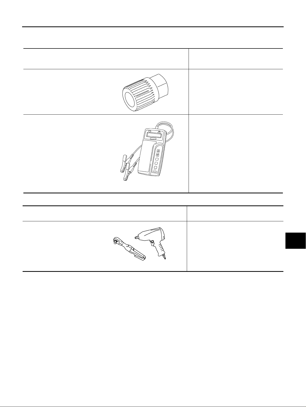
Alternator pulley adapter
PKIA1241E
—
(J-44373 Model 620)
Battery/Starting/Charging system
tester
SEL403X
Description
Removing alternator pulley
Commercial Service Tools AKS00BHE
B
C
D
E
F
G
H
I
Tool number
Tool name
Power tool Loosening bolts and nuts
PBIC0190E
Description
J
SC
L
M
Revision: 2006 July 2006 X-Trail
SC-3
BATTERY
BATTERY PFP:00011 How to Handle Battery AKS00BHF
CAUTION:
● If it becomes necessary to start the engine with a booster battery and jumper cables, use a 12-volt
booster battery.
● After connecting battery cables, ensure that they are tightly clamped to battery terminals for good
contact.
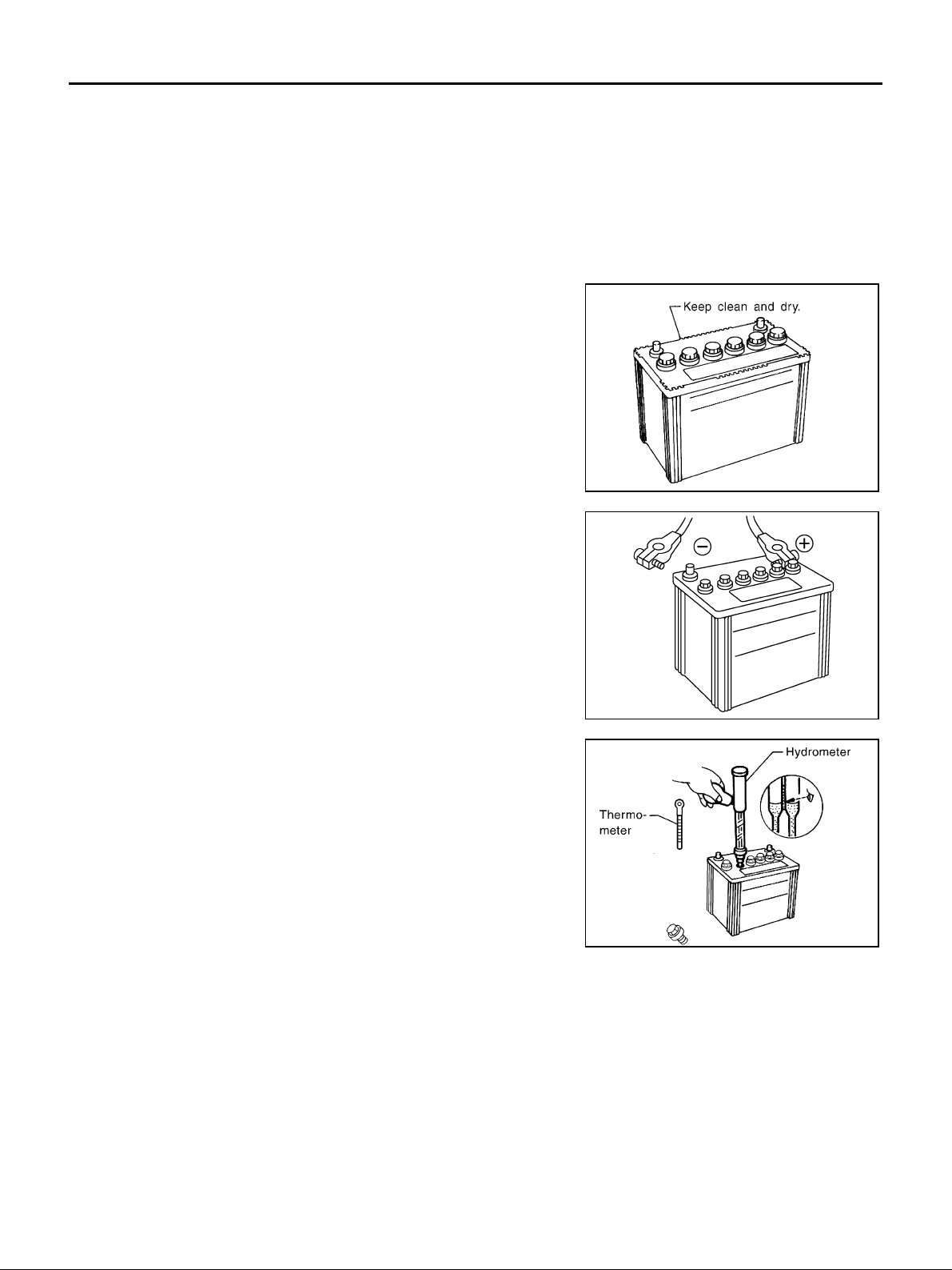
METHODS OF PREVENTING OVER-DISCHARGE
The following precautions must be taken to prevent over-discharging
a battery.
● The battery surface (particularly its top) should always be kept
clean and dry.
● The terminal connections should be clean and tight.
● At every routine maintenance, check the electrolyte level.
This also applies to batteries designated as “low maintenance”
and “maintenance -fre e” .
MEL040F
● When the vehicle is not going to be used over a long period o f
time, disconnect battery cable at negative ter minal.
● Check the charge condition of the battery.
Periodically ch eck the specific gravity of the el ectrolyte. Keep a
close check on charge condition to prevent over-discharge.
ELA0349D
MEL042F
Revision: 2006 July 2006 X-Trail
SC-4
BATTERY
CHECKING ELECTROLYTE LEVEL
WARNING:
Do not allow battery flu id to c ome i n c ontact with sk in, e ye s, fabrics, or painted surfaces. After touching a battery, do not touch or rub your eyes until you have thoroughly washed your hands. If acid contacts eyes, skin or clothing, immediately fl ush with water for 15 minutes and seek medical attention.
● Remove the cell plug using a suitable tool.
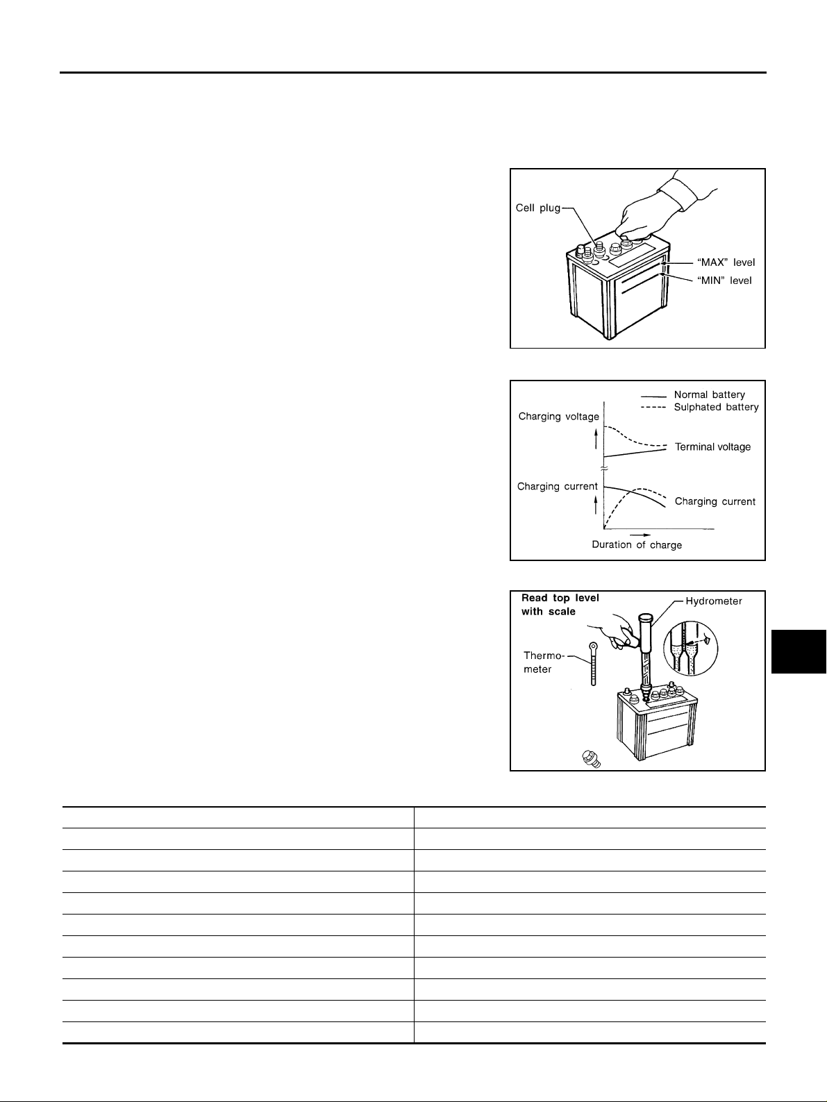
● Add distilled water up to the MAX level.
MEL043F
A
B
C
D
E
Sulphation
A battery will be completely discha rged if it is left unattended
for a long time and the specific gravity will become less than
1.100. This may result in sulphation on the cell plates.
To determine if a b attery h as been “sulph ate d”, no te its voltage
and current when charging it. As shown in the figu re, less current and higher voltage are observed in the initial stage of
charging sulphated batteries .
A sulphated battery may so metimes be brought back into service by means of a long, slow charge, 12 hours or more, followed by a battery capacity test.
SPECIFIC GRAVITY CHECK
1. Read hydrometer and thermom eter indications at eye level.
2. Use the chart be low to corr ect your hydro meter rea ding accord ing to electrolyte temperature.
PKIA2353E
MEL042FA
F
G
H
I
J
SC
L
M
Hydrometer Temperature Correction
Battery electrolyte temperature °C (°F) Add to specific gravity reading
71 (160) 0.032
66 (150) 0.028
60 (140) 0.024
54 (130) 0.020
49 (120) 0.016
43 (110) 0.012
38 (100) 0.008
32 (90) 0.004
27 (80) 0
21 (70) −0.004
Revision: 2006 July 2006 X-Trail
SC-5

BATTERY
Battery electrolyte temperature °C (°F) Add to specific gravity reading
16 (60) −0.008
10 (50) −0.012
4 (40) −0.016
−1 (30) −0.020
−7 (20) −0.024
−12 (10) −0.028
−18 (0) −0.032
Corrected specific gravity Approximate charge condition
1.260 - 1.280 Fully charged
1.230 - 1.250 3/4 charged
1.200 - 1.220 1/2 charged
1.170 - 1.190 1/4 charged
1.140 - 1.160 Almost discharged
1.110 - 1.130 Completely discharged
CHARGING THE BATTERY
CAUTION:
● Do not “quick charge” a fully discharged battery.
● Keep the battery away from open flame while it is being charged.
● When connecting the charger, connect the leads first, then turn on the charger. Do not turn on the
charger first, as this may cause a spark.
● If battery electrolyte te mpe r atu r e ris es ab ove 55 °C (131 °F), stop chargin g. A lwa ys charge battery
at a temperature below 55 °C (131 °F).
Charging Rates
Amps Time
50 1 hour
25 2 hours
10 5 hours
5 10 hours
Do not charge at more than 50 ampere rate.
NOTE:
The ammeter reading on your battery charger will automatically decrease as the battery charges. This indicates that the voltage of the battery is increasing normally as the state of charge improves. The charging amps
indicated above refer to initial charge rate.
● If, after charging, the specific gravity of any two cells varies more than 0.050, the battery should be
replaced.
Revision: 2006 July 2006 X-Trail
SC-6
BATTERY
Trouble Diagnoses with Battery/Starting/Charging System Tester (Battery) AKS00BHG
CAUTION:
When working with batteries, always wear appropriate eye protection.
NOTE:
● To ensure a complete and thorough diagnosis, the battery, starter and generator test segments must be
done as a set from start to finish.
● If battery surface charge is detected while testing, the tester will prompt you to turn on the headlamps to
remove the surface charge.
● If necessary, the tester will prompt you to determine if the battery temperature is above or below 0 °C (32
°F). Choose the appropriate selection by pressing the up or down arrow button, then press “ENTER” to
make the selection.
1. Turn of f all l oads on the vehi cle e lectr ica l sys tem. C lean o r rep a ir
as necessary.
2. Visually inspect the battery, battery terminals and cable ends
with ignition switch in “OFF” position.
NOTE:
The contact surface between the battery terminals, cable ends
and tester leads m ust be clean for a valid tes t. A poor connection will prevent testing and a “CHECK CONNECTION” message will appear during the test procedures. If this occurs, clean
the battery terminals, reconnect them and restart the test.
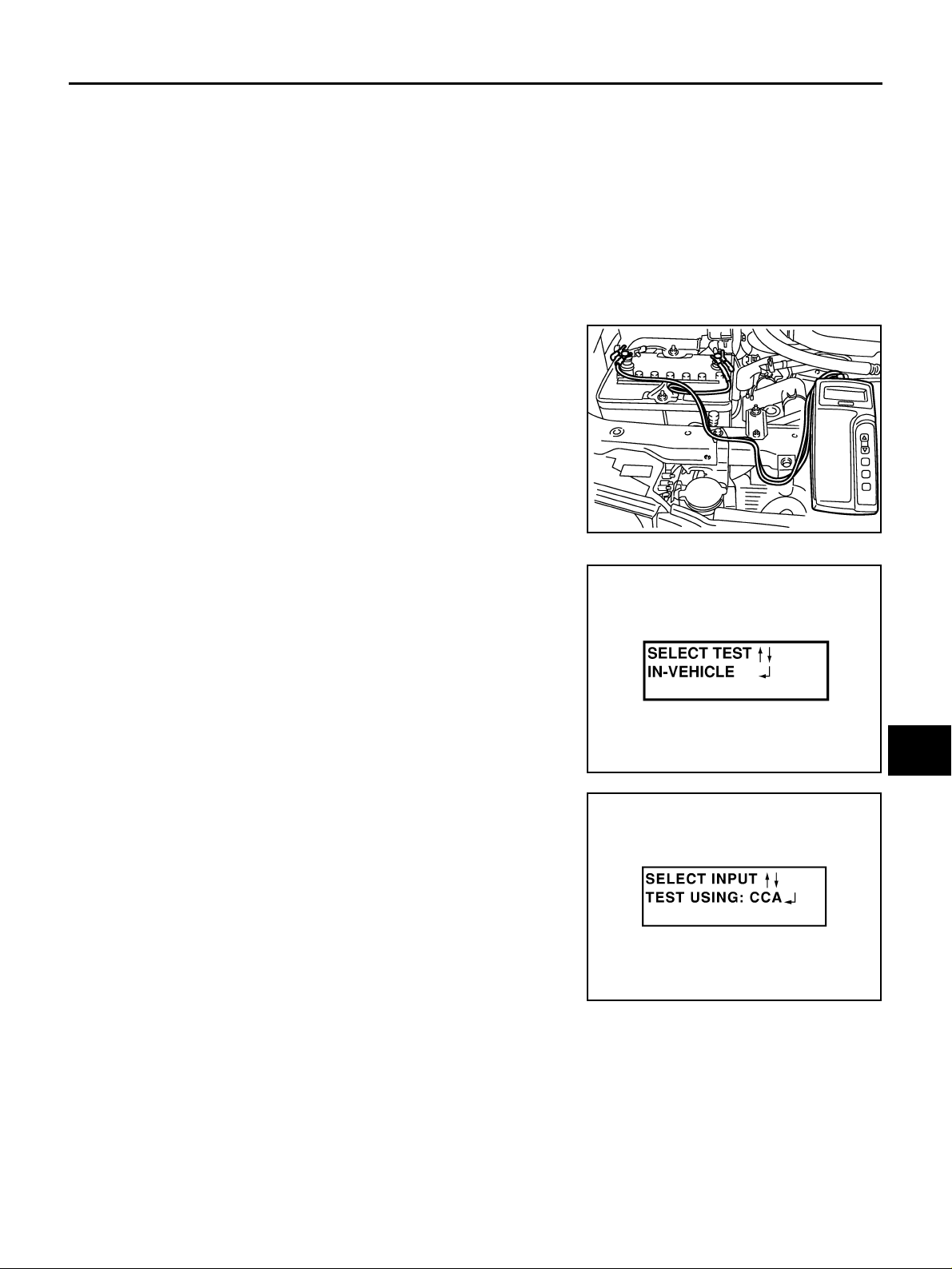
3. Connect the red tester le ad clamp to the positive battery terminal, and the black to the negative battery terminal.
4. The tester will turn on automatically. Using the arrow keys,
select “IN-VEHICLE” on the tester and then press the “ENTER”
key.
SEL404X
A
B
C
D
E
F
G
H
I
5. Locate the ba ttery type and rating stamped or written on the
top case of the battery to be tested.
NOTE:
The battery rating will have either of the following.
● CCA: Cold Cranking Amps (490 CCA, 550 CCA, etc.)
● JIS: Japanese Industrial Standard.
When using the battery tester: Use the CCA rating only.
● The tester requires the CCA rating for the battery be entered
exactly as it is written or stamped on the battery.
● U.S. market: Refer to the latest “Battery Testing” Technical
Service Bu lle ti n (TS B) f o r a ch art wh ic h c on tains these rat i ng s
listed by vehicle.
● You must not use the JIS rating.
6. Using the arrow and “ENTER” keys alternately, select the battery type and rating.
NOTE:
The tester lists five choices; CCA, JIS, IEC, DIN, and EN. Use only the CCA choice .
SEL405X
PKIC1310E
J
SC
L
M
Revision: 2006 July 2006 X-Trail
SC-7
BATTERY
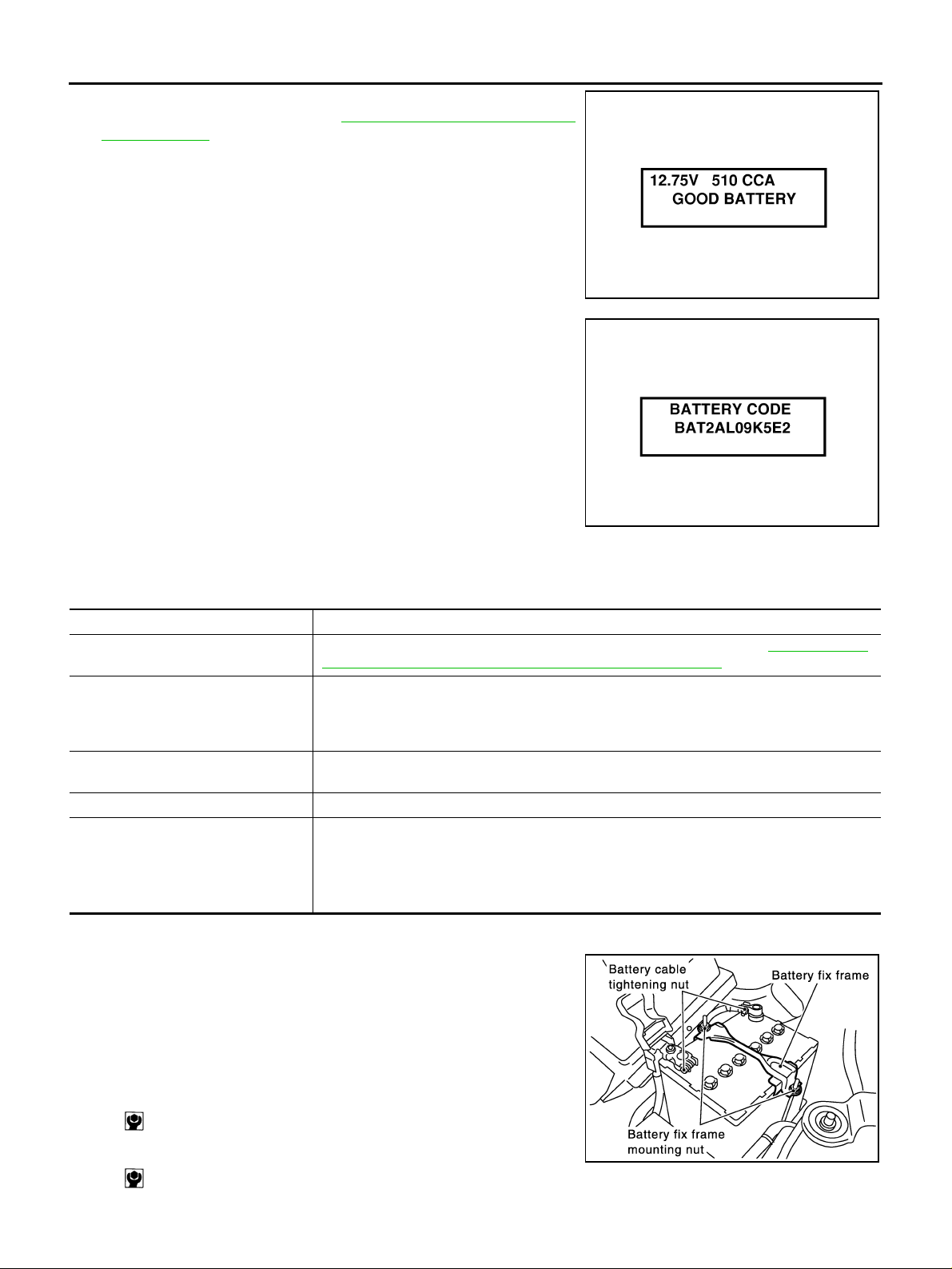
7. Press “ENTER” to begin the test. Diagnosis results are displayed on the tester. Refer to SC-8, "
ITEM CHART" .
8. Press “ENTER”, then test output code is displayed. Record the
test output code on the repair order.
9. Toggle back to the “DIAGNOSTIC SCREEN” for test results.
NOTE:
● If necessary, the tester will ask the user to determine if the
battery has just been charged. Choose the appropriate selection by pressi ng the up or down arrow button and then pres s
the “ENTER” button to make the se le cti on .
● When testing a battery installed in a vehicle that has recently
been driven, select “BEFORE CHARGE”.
● If the battery h as just be en slow c harged du e to a “CHAR GE
& RETEST” decision by the tester, and the tester asks the user “BEFORE CHARGE/AFTER
CHARGE”, select “AFTER CHARGE”.
DIAGNOSTIC RESULT
SEL407X
SEL576X
DIAGNOSTIC RESULT ITEM CHART
Diagnostic item Service procedure
GOOD BATTERY
REPLACE BATTERY
BAD CELL-REPLACE
GOOD-RECHARGE Perform the slow battery charging procedure. (Initial rate of charge is 10 A for 12 hours.)
CHARGE & RETEST
Battery is OK, go to “Trouble Diagnoses”, “STARTING SYSTEM”. Refer to SC-12, "
Diagnoses with Battery/Starting/Charging System Tester (Starting)" .
Replace battery.
Before replacing battery, clean the battery cable clamps and battery terminals. Perform battery test again with Battery/Starting/Charging system tester. If second test result is “Replace
Battery”, then do so. Perform battery test again to confirm repair.
Replace the battery. Perform battery test again with Battery/Starting/Charging system tester
to confirm repair.
Perform the slow battery charging. (Initial rate of charge is 10 A for 12 hours.)
Perform battery test again with Battery/Starting/Charging system tester to confirm repair.
NOTE:
If the tester asks the user “BEFORE CHARGE/AFTER CHARGE”, select “AFTER
CHARGE”.
Trouble
Removal and Installation AKS00B6P
Observe the following to ensure proper servicing.
CAUTION:
● When removing, disconnect battery cable at negative termi-
nal first. But for installation, connect ba ttery cable to positive terminal first.
● Tighten parts to the specified torque shown below.
Battery fix frame mounting nut:
: 4.4 N·m (0.45 kg-m, 39 in-lb)
Battery cable tightening nut:
SKIA0068E
: 4.0 N·m (0.41 kg-m, 35 in-lb)
Revision: 2006 July 2006 X-Trail
SC-8

STARTING SYSTEM
STARTING SYSTEM PFP:00011
System Description AKS00B6Z
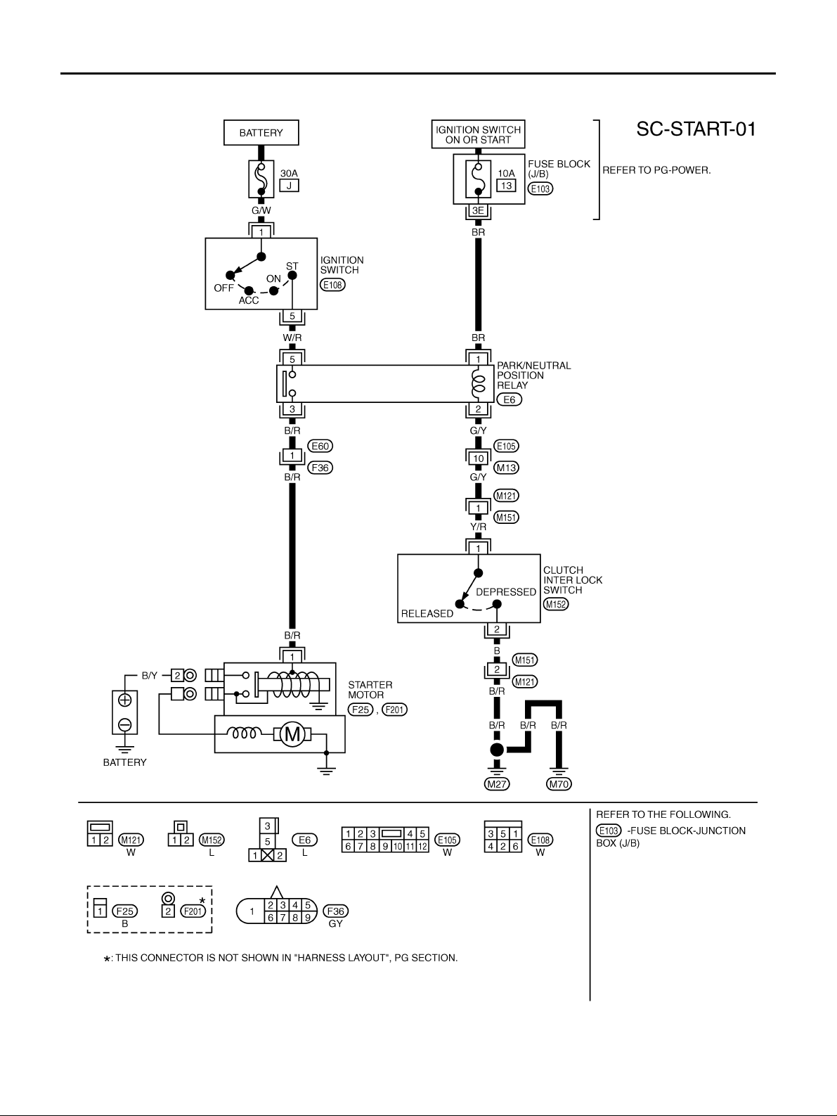
M/T MODELS
Power is supplied at all times
● through 30A fusible link (letter J, located in the fuse and fusible link box)
● to ignition switch terminal 1.
With the ignition switch in the START position, power is supplied
● from ignition switch terminal 5
● to park/neutral position relay terminal 5.
With the ignition switch in the ON or START position, power is supplied
● through 10A fuse [No,13 located in the fuse block (J/B)]
● to park/neutral position relay terminal 1.
With the clutch interlock switch is depressed, ground is supplied
● to park/neutral position relay terminal 2
● through clutch interlock switch terminals 1 and 2, and
● through grounds M27 and M70.
Then park/neutral posit ion relay is energized and power is supplied
● from park/neutral position relay terminal 3
● to starter motor harness connector terminal 1.
The starter motor plunge r closes and provides a closed ci rcuit between the battery and starter mo tor. The
starter motor is grounded to engine block. With power and ground supplied, cranking occurs and the engine
starts.
A
B
C
D
E
F
G
H
A/T MODELS
Power is supplied at all times
● through 30A fusible link (letter J, located in fuse and fusible link box)
● to ignition switch terminal 1.
With the ignition switch in the START position, power is supplied
● from ignition switch terminal 5
● to park/neutral position relay terminal 5.
With the ignition switch in the ON or START position, power is supplied
● through 10A fuse [No,13 located in the fuse block (J/B)]
● to park/neutral position relay terminal 1.
With the selector lever in the P or N position, ground is supplied
● to park/neutral position relay terminal 2
● through park/neutral position switch terminals 1 and 2, and
● through grounds F9 and F10.
Then park/neutral posit ion relay is energized and power is supplied
● from park/neutral position relay terminal 3
● to starter motor harness connector terminal 1.
The starter motor plunge r closes and provides a closed ci rcuit between the battery and starter mo tor. The
starter motor is grounded to engine block. With power and ground supplied, cranking occurs and the engine
starts.
I
J
SC
L
M
Revision: 2006 July 2006 X-Trail
SC-9
STARTING SYSTEM
Wiring Diagram — START — AKS00B70
M/T MODELS
TKWB0147E
Revision: 2006 July 2006 X-Trail
SC-10
 Loading...