


 Loading...
J AIR CONDITIONER
SECTION MTC
MANUAL AIR CONDITIONER
A
B
C
D
CONTENTS
E
PRECAUTIONS ......................................................... |
|
2 |
Precautions for Supplemental Restraint System |
|
|
(SRS) “AIR BAG” and “SEAT BELT PRE-TEN- |
|
|
SIONER” ................................................................. |
|
2 |
Wiring Diagrams and Trouble Diagnosis ................. |
|
2 |
TROUBLE DIAGNOSIS ............................................. |
|
3 |
How to Perform Trouble Diagnoses for Quick and |
|
|
Accurate Repair ...................................................... |
|
3 |
WORK FLOW ....................................................... |
|
3 |
SYMPTOM TABLE ............................................... |
|
3 |
ComponentPartsandHarnessConnectorLocation..... |
4 |
|
PASSENGER COMPARTMENT .......................... |
|
4 |
Discharge Air Flow .................................................. |
|
5 |
Wiring Diagram —HEATER— ............................. |
..... 6 |
|
Operational Check .................................................. |
|
7 |
CHECKING BLOWER .......................................... |
|
7 |
CHECKING DISCHARGE AIR ............................. |
|
7 |
CHECKING RECIRCULATION ............................ |
|
7 |
CHECKING TEMPERATURE DECREASE ......... |
|
8 |
CHECKING TEMPERATURE INCREASE ........... |
|
8 |
Mode Door .............................................................. |
|
9 |
INSPECTION FLOW ............................................ |
|
9 |
Air Mix Door .......................................................... |
|
10 |
INSPECTION FLOW .......................................... |
|
10 |
Intake Door Motor Circuit ....................................... |
|
11 |
INSPECTION FLOW ........................................... |
|
11 |
COMPONENT DESCRIPTION ........................... |
|
11 |
DIAGNOSTIC PROCEDURE FOR INTAKE |
|
|
DOOR MOTOR .................................................. |
|
12 |
Blower Motor Circuit .............................................. |
|
15 |
INSPECTION FLOW .......................................... |
|
15 |
DIAGNOSTIC PROCEDURE FOR BLOWER |
|
|
MOTOR .............................................................. |
|
16 |
COMPONENT INSPECTION ............................. |
|
18 |
Insufficient Heating ................................................ |
|
19 |
INSPECTION FLOW .......................................... |
|
19 |
CONTROLLER ........................................................ |
|
21 |
Removal and Installation ....................................... |
|
21 |
REMOVAL .......................................................... |
|
21 |
INSTALLATION .................................................. |
21 |
Disassembly and Assembly ................................... |
21 |
BLOWER UNIT ........................................................ |
22 |
Removal and Installation ....................................... |
22 |
REMOVAL .......................................................... |
22 |
INSTALLATION .................................................. |
22 |
Disassembly and Assembly ................................... |
23 |
BLOWER MOTOR ................................................... |
24 |
Removal and Installation ....................................... |
24 |
REMOVAL .......................................................... |
24 |
INSTALLATION .................................................. |
24 |
BLOWER FAN RESISTOR ...................................... |
25 |
Removal and Installation ....................................... |
25 |
REMOVAL .......................................................... |
25 |
INSTALLATION .................................................. |
25 |
INTAKE DOOR MOTOR .......................................... |
26 |
Removal and Installation ....................................... |
26 |
REMOVAL .......................................................... |
26 |
INSTALLATION .................................................. |
26 |
HEATER UNIT .......................................................... |
27 |
Removal and Installation ....................................... |
27 |
REMOVAL .......................................................... |
27 |
INSTALLATION .................................................. |
28 |
Disassembly and Assembly ................................... |
29 |
HEATER CORE ........................................................ |
30 |
Removal and Installation ....................................... |
30 |
REMOVAL .......................................................... |
30 |
INSTALLATION .................................................. |
30 |
MODE DOOR ........................................................... |
31 |
Control Linkage Adjustment .................................. |
31 |
MODE DOOR CONTROL CABLE ...................... |
31 |
AIR MIX DOOR ........................................................ |
32 |
Control Linkage Adjustment .................................. |
32 |
AIR MIX DOOR CONTROL CABLE ................... |
32 |
DUCTS AND GRILLES ............................................ |
33 |
Removal and Installation ....................................... |
33 |
REMOVAL .......................................................... |
33 |
INSTALLATION .................................................. |
36 |
F
G
H
I
MTC
K
L
M
MTC-1
|
PRECAUTIONS |
|
|
PRECAUTIONS |
PFP:00001 |
Precautions for Supplemental Restraint System (SRS) “AIR BAG” and “SEAT BELT PRE-TENSIONER” EJS004L7
The Supplemental Restraint System such as “AIR BAG” and “SEAT BELT PRE-TENSIONER”, used along with a front seat belt, helps to reduce the risk or severity of injury to the driver and front passenger for certain types of collision. Information necessary to service the system safely is included in the SRS and SB section of this Service Manual.
WARNING:
●To avoid rendering the SRS inoperative, which could increase the risk of personal injury or death in the event of a collision which would result in air bag inflation, all maintenance must be performed by an authorized NISSAN/INFINITI dealer.
●Improper maintenance, including incorrect removal and installation of the SRS, can lead to personal injury caused by unintentional activation of the system. For removal of Spiral Cable and Air Bag Module, see the SRS section.
●Do not use electrical test equipment on any circuit related to the SRS unless instructed to in this Service Manual. SRS wiring harnesses can be identified by yellow and/or orange harnesses or harness connectors.
Wiring Diagrams and Trouble Diagnosis |
EJS000WA |
When you read wiring diagrams, refer to the following:
●GI-14, "How to Read Wiring Diagrams" in GI section.
●PG-3, "Wiring Diagram — POWER — " in PG section. When you perform trouble diagnosis, refer to the following:
●GI-10, "How to Follow Trouble Diagnoses" in GI section.
●GI-23, "How to Perform Efficient Diagnosis for an Electrical Incident" in GI section.
MTC-2
TROUBLE DIAGNOSIS
TROUBLE DIAGNOSIS
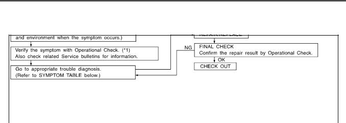
How to Perform Trouble Diagnoses for Quick and Accurate Repair
WORK FLOW
PFP:00004
A
EJS001FB
B
C
D
|
SHA900E |
E |
|
*1 MTC-7, "Operational Check" |
|
|
|
|
SYMPTOM TABLE |
|
|
|
|
|
|
F |
|
Symptom |
Reference Page |
|
|
||
|
|
|
|||
|
|
|
|
|
|
Air outlet does not change. |
Go to Trouble Diagnosis Procedure for Mode Door. |
MTC-9, "Mode |
|
||
Door" |
|
||||
|
|
G |
|||
|
|
|
|
||
Discharge air temperature does not change. |
Go to Trouble Diagnosis Procedure Air Mix Door. |
MTC-10, "Air Mix |
|||
|
|||||
Door" |
|
||||
|
|
|
|||
|
|
|
|
|
|
Intake door does not change. |
|
MTC-11, "Intake |
H |
||
|
Go to Trouble Diagnosis Procedure for Intake Door Motor Circuit. |
Door Motor Cir- |
|||
Intake door motor does not operate normally. |
|||||
|
|||||
|
cuit" |
|
|||
|
|
|
|||
|
|
|
|
|
|
Blower motor operation is malfunctioning. |
Go to Trouble Diagnosis Procedure for Blower Motor Circuit. |
MTC-15, "Blower |
I |
||
Motor Circuit" |
|||||
|
|
||||
|
|
|
|
|
|
Insufficient heating |
Go to Trouble Diagnosis Procedure for Insufficient Heating. |
MTC-19, "Insuffi- |
|
||
cient Heating" |
|
||||
|
|||||
|
|
|
|||
|
|
|
|
MTC |
|
|
|
|
|
||
|
|
|
|
|
|
|
|
|
|
K |
|
|
|
|
|
L |
|
|
|
|
|
M |
|
MTC-3
TROUBLE DIAGNOSIS
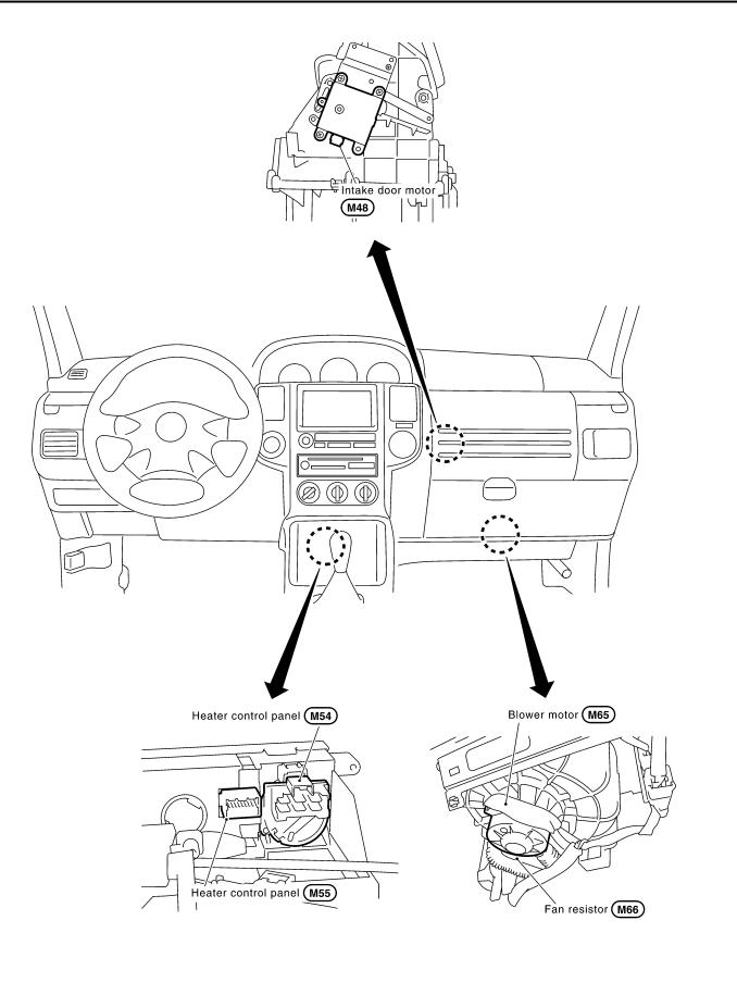
Component Parts and Harness Connector Location
PASSENGER COMPARTMENT
EJS001FC
RJIA2845E
MTC-4

TROUBLE DIAGNOSIS
Discharge Air Flow
EJS001HF
A
B
C
D
E
F
G
H
I
MTC
K
L
M
SJIA0441E
MTC-5
TROUBLE DIAGNOSIS
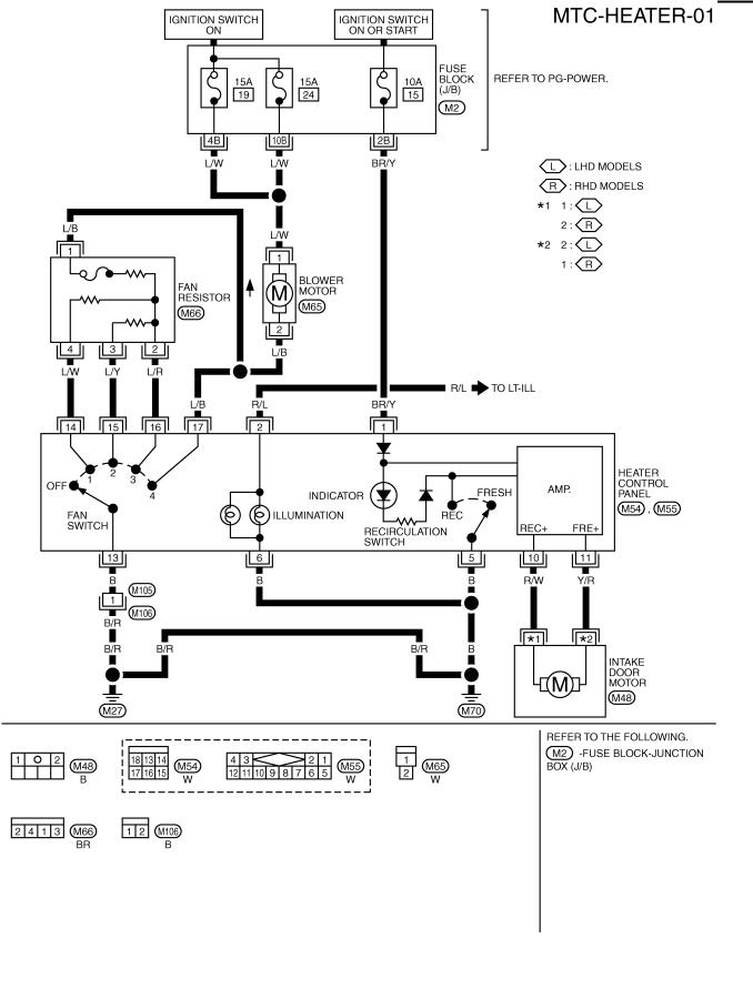
Wiring Diagram —HEATER—
EJS001FD
TJWA0076E
MTC-6
TROUBLE DIAGNOSIS
Operational Check
The purpose of the operational check is to confirm that the system operates properly.
Conditions |
:Engine running at usual operating temperature |
CHECKING BLOWER
1.Turn fan switch to 1st-speed. Blower should operate on low speed.
2.Then turn fan switch to 2nd-speed, and continue checking blower speed until all speeds are checked.
3.Leave blower on Max. speed.
If NG, go to trouble diagnosis procedure for MTC-15, "Blower Motor Circuit" .
If OK, continue with the check.
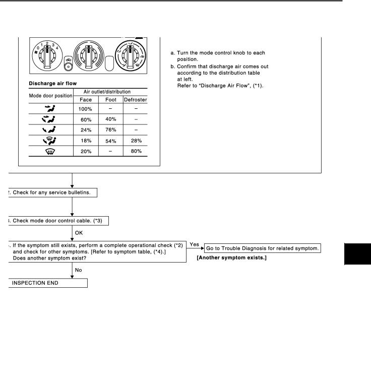
CHECKING DISCHARGE AIR
1.Turn mode control dial to each position.
2.Confirm that discharge air comes out according to the air distribution table. Refer to MTC-5, "Discharge Air Flow" .
If NG, go to trouble diagnosis procedure for MTC-9, "Mode Door" . If OK, continue the check.
CHECKING RECIRCULATION
1.Press REC switch. Recirculation indicator should eliminate.
2.Press REC switch again. Recirculation indicator should not illuminate.
3.Listen for intake door position change (you should hear blower sound change slightly).
If NG, go to trouble diagnosis procedure for MTC-11, "Intake Door Motor Circuit" .
If OK, continue the check.
EJS001FE
A
B
C
D
E
RJIA0587E
F
G
H
I
RJIA0588E
MTC
K
L
RJIA0492E M
RJIA0589E
MTC-7

TROUBLE DIAGNOSIS
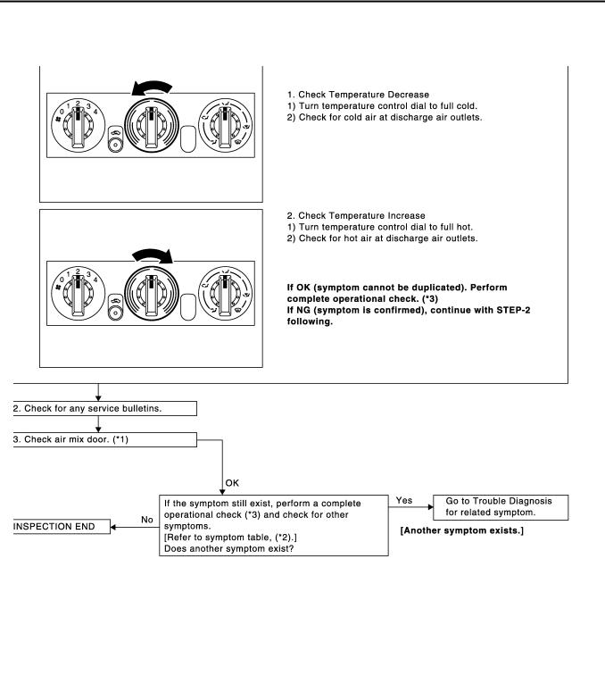
CHECKING TEMPERATURE DECREASE
1.Turn temperature control dial to full cold position.
2.Check for cold air at discharge air outlets.
If NG, go to trouble diagnosis procedure for MTC-10, "Air Mix Door" If OK, continue the check.
CHECKING TEMPERATURE INCREASE
1.Turn temperature control dial to full hot position.
2.Check for hot air at discharge air outlets.
If NG, go to trouble diagnosis procedure for MTC-19, "Insufficient Heating" .
If all operational check are OK (symptom cannot be duplicated), go to Incident Simulation Tests in GI-23, "How to Perform Efficient Diagnosis for an Electrical Incident" and perform tests as outlined to simulate driving conditions environment. If symptom appears, refer to MTC-3, "SYMPTOM TABLE" and perform applicable trouble diagnosis procedures.
RJIA0590E
RJIA0591E
MTC-8
TROUBLE DIAGNOSIS
Mode Door |
EJS001FF |
A
SYMPTOM: Air outlet does not change.
INSPECTION FLOW
B
C
D
E
F
G
H
I
MTC
K
L
M
RJIA0592E
*1 MTC-5, "Discharge Air Flow". |
*2 MTC-7, "Operational Check". |
*3 MTC-31, "MODE DOOR". |
*4 MTC-3, "SYMPTOM TABLE".
MTC-9
TROUBLE DIAGNOSIS
Air Mix Door |
EJS001FG |
SYMPTOM: Air mix door does not change.
INSPECTION FLOW
RJIA0593E
*1 MTC-32, "AIR MIX DOOR". |
*2 MTC-3, "SYMPTOM TABLE". |
*3 MTC-7, "Operational Check". |
MTC-10
TROUBLE DIAGNOSIS
Intake Door Motor Circuit |
EJS004HC |
SYMPTOM:
●Intake door does not change.
●Intake door motor does not operate normally.
INSPECTION FLOW
RJIA0594E
*1 MTC-11, "Intake Door Motor Circuit". *2 MTC-7, "Operational Check". |
*3 MTC-3, "SYMPTOM TABLE". |
A
B
C
D
E
F
G
H
I
MTC
K
COMPONENT DESCRIPTION |
|
|
Intake Door Motor |
|
L |
The intake door motor is attached to the intake unit. It rotates so that |
|
|
|
|
|
air is drawn from inlets set by the heater control panel. Motor rotation |
|
|
is conveyed to a lever which activates the intake door. |
|
M |
|
|
RJIA0519E
MTC-11
Loading...