

Page 1
FOREWORD READ FIRST—THEN DRIVE SAFELY
Welcome to the growing family of new NISSAN
owners. This vehicle is delivered to you with
confidence. It was produced using the latest
techniques and strict quality control.
This manual was prepared to help you understand the operation and maintenance of your
vehicle sothat youmay enjoymany miles(kilometers) ofdriving pleasure. Please read through this
manual before operating your vehicle.
A separate Warranty Information Booklet
explains details about the warranties covering your vehicle. The “NISSAN Service
and Maintenance Guide” explains details
about maintaining and servicing your vehicle. Additionally, a separate Customer
Care/Lemon Law Booklet (U.S. only) will
explain how to resolve any concerns you
may have with your vehicle, as well as
clarify your rights under your state’s lemon
law.
Your NISSAN dealership knows your vehicle
best. When you require any service or have any
questions, they will be glad to assist you with the
extensive resources available to them.
Before driving your vehicle please read this Owner’s Manual carefully. This will ensure familiarity
with controls and maintenance requirements, assisting you in the safe operation of your vehicle.
WARNING
IMPORTANT SAFETY INFORMATION REMINDERS FOR SAFETY!
Follow these important driving rules to
help ensure a safe and comfortable trip
for you and your passengers!
● NEVER drive under the influence of alcohol or drugs.
● ALWAYS observe posted speed limits
and never drive too fast for conditions.
● ALWAYS use your seat belts and appropriate child restraint systems. Pre-teen
children should be seated in the rear
seat.
● ALWAYS provide information about the
proper use of vehicle safety features to
all occupants of the vehicle.
● ALWAYS review this owner’s manual for
important safety information.
For descriptions specified for four-wheel drive
models, a
ning of the applicable sections/items.
mark is placed at the begin-
As with other vehicles with features for
off-road use, failure to operate four-wheel
drive models correctly may result in loss of
control or an accident. Be sure to read
“Driving safety precautions” in the “Starting and driving” section of this manual.
ON-PAVEMENT AND OFF-ROAD DRIVING
This vehicle will handle and maneuver
differently from an ordinary passenger
car because it has a higher center of
gravity for off-road use. As with other
vehicles with features of this type, failure to operate this vehicle correctly may
result in loss of control or an accident.
Be sure to read “On-pavement and offroad driving precautions”, and “Avoiding collision and rollover”, and “Driving
safety precautions”, in the “Starting and
driving” section of this manual.
MODIFICATION OF YOUR VEHICLE
This vehicle should not be modified.
Modification could affect its performance,
safety or durability, and may even violate
governmental regulations. In addition,
damage or performance problems resulting from modifications may not be covered under NISSAN warranties.
Page 2
WHEN READING THE MANUAL
This manual includes information for all options
available on this model. Therefore, you may find
some information that does not apply to your
vehicle.
All information, specifications and illustrations in
this manual are those in effect at the time of
printing. NISSAN reserves the right to change
specifications or design without notice and without obligation.
IMPORTANT INFORMATION ABOUT
THIS MANUAL
You will see various symbols in this manual. They
are used in the following ways:
WARNING
This is used to indicate the presence of a
hazard that could cause death or serious
personal injury. To avoid or reduce the
risk, the procedures must be followed
precisely.
CAUTION
This is used to indicate the presence of a
hazard that could cause minor or moderate personal injury or damage to your vehicle. To avoid or reduce the risk, the procedures must be followed carefully.
APD1005
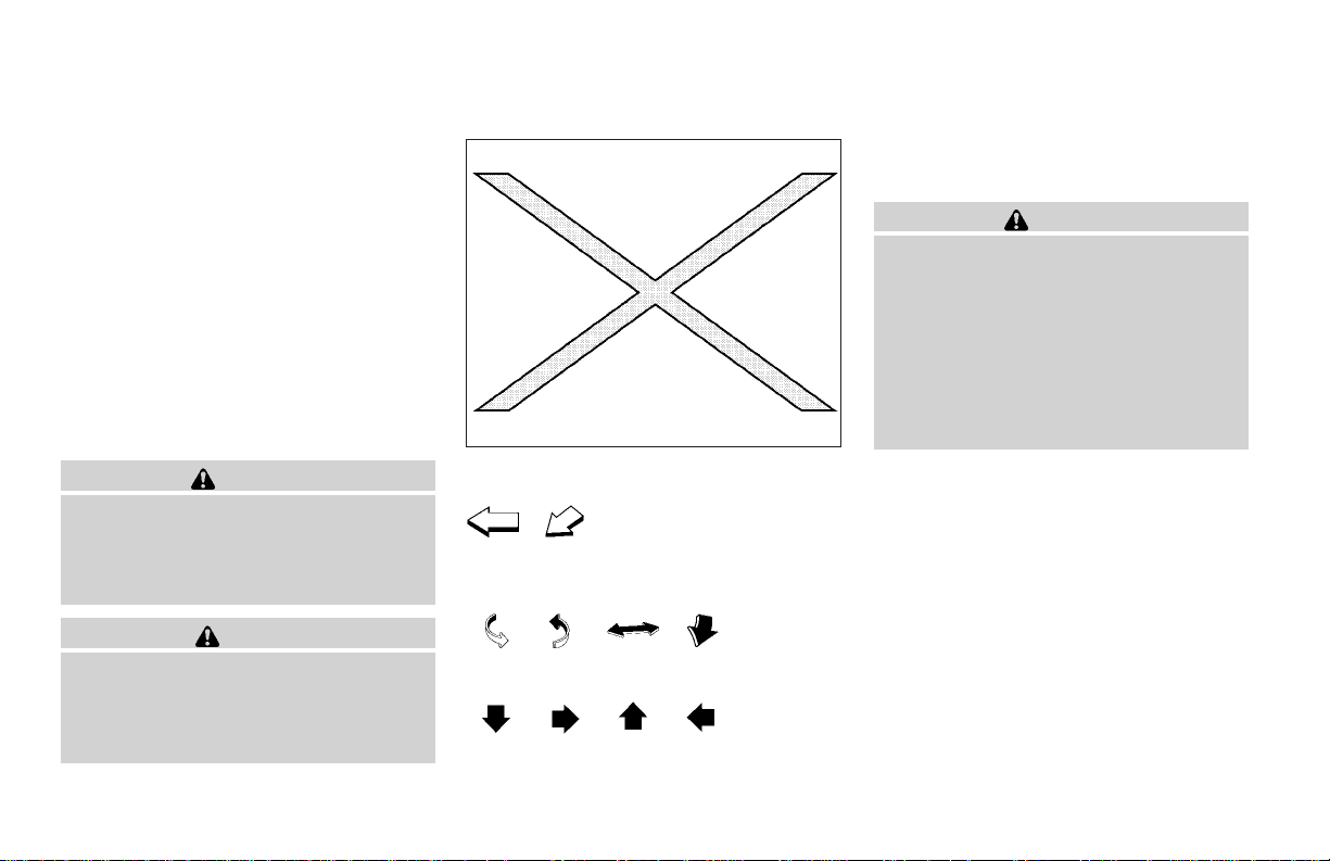
If you see this symbol, it means “Do not do this”
or “Do not let this happen.”
If you see a symbol similar to these in an illustration, it means the arrow points to the front of the
vehicle.
Arrows in an illustration that are similar to these
indicate movement or action.
Arrows in an illustration that are similar to these
call attention to an item in the illustration.
CALIFORNIA PROPOSITION 65
WARNING
WARNING
Engine exhaust, some of its constituents,
and certain vehicle components contain
or emit chemicals known to the State of
California to cause cancer and birth defects or other reproductive harm. In addition, certain fluids contained in vehicles
and certain products of component wear
contain or emit chemicals known to the
State of California to cause cancer and
birth defects or other reproductive harm.
© 2004 NISSAN NORTH AMERICA, INC.
GARDENA, CALIFORNIA
All rights reserved. No part of this Owner’s
Manual may be reproduced orstored ina retrieval
system, or transmitted in any form, or by any
means, electronic, mechanical, photocopying,
recording or otherwise, without the prior written
permission of Nissan North America, Inc., Gardena, California.
Page 3
WELCOME TO THE WORLD OF NISSAN
WFW0002
Your new NISSAN is the result of our dedication to
produce the finest in safe, reliable and economical
transportation. Your vehicle is the product of a successful worldwide company that manufactures cars
and trucks in over 17countries and distributes them
in 170 nations.
NISSAN vehicles are designed and manufactured
by Nissan Motor Co., Ltd. which was founded in
Tokyo, Japan in 1933, and NISSAN affiliates worldwide, collectively growing to becomethe fifth largest
automaker in the world. In addition to cars and
trucks, NISSAN also makes forklift trucks, marine
engines, boats and other diversified products.
NISSAN has made a substantial and growing investment in North America. NISSAN’s commitment
is over $6 billion dollars in capital investments in
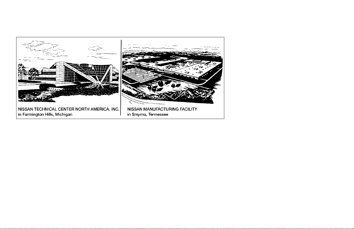
facilities across the continent. Some of the facilities
include the Nissan Manufacturing facilities in Canton, Mississippi and in Smyrna, Tennessee, vehicle
styling design at Nissan Design America, Inc. in San
Diego, California, and engineering at Nissan Technical Center North America in Farmington Hills,
Michigan. Additionally, NISSAN employs more than
21,000 people throughout the United States,
Canada, and Mexico. An additional 60,000 people
work for the 1,250 NISSAN and INFINITI dealers
across North America.
NISSAN is also a substantial contributor to the
Canadian economy. Nissan Canada Inc., its suppliers and over 150 dealers employ approximately
4,500 people. These include company employees
and thestaffs of NISSAN dealers all across Canada.
In addition, many Canadians work for companies
that supply NISSAN and NISSAN dealers with materials and services ranging from the operation of
port facilities and transportation services, to the
supply of lubricants, parts and accessories.
NISSAN pioneered the use of electronics and computers in automobiles, and has led the industry in
improving both performance and fuel efficiency
through new engine designs and the use of synthetic materials to reduce vehicle weight. The company has also developed waysto build qualityinto its
vehicles at each stage of the production process,
both through extensive use of automation and —
most importantly — through an awareness that
are the central element in quality control.
people
From the time the parts arrived from our suppliers
until you took delivery of your new NISSAN, dozens
of checks were made toensure that only the bestjob
was being done in producing and delivering your
vehicle. NISSAN also takes greatcare toensure that
when you take your NISSAN to your dealer for
maintenance, the service technician will perform his
work according to the quality standards that have
been established by NISSAN.
Safety has also been builtinto your NISSAN. As you
know, seat belts are an integral part of the safety
systems that will help protect you and your passengers in the event of a sudden stop or an accident.
We urge you to use the seat belts every time you
drive the vehicle.
The NISSAN story of growth and achievement reflects our major goal: to provide you, our customer,
with avehicle thatis builtwith quality and craftsmanship — a product that we can be proud to build and
you can be proud to own.
Page 4

NISSAN CUSTOMER CARE PROGRAM
NISSAN CARES...
Both NISSAN and your NISSAN dealer are dedicated to serving all your automotive needs. Your satisfaction with your vehicle and your NISSAN dealer are
our primary concerns. Your NISSAN dealer is always available to assist you with all your automobile sales and service needs.
However, if there is something that your NISSAN
dealer cannotassist youwith or you would like to
provide NISSAN directly with comments or
questions, please contact the NISSAN Consumer Affairs Department using our toll-free
number:
For U.S. customers
1-800-NISSAN-1
(1-800-647-7261)
For Canadian customers
1-800-387-0122
We appreciate your interest in NISSAN and thank you for buying a quality NISSAN vehicle.
The Consumer Affairs Department will ask for
the following information:
– Your name, address, and telephone number
– Vehicle identification number (attached to the
top of the instrument panel on the driver’s
side)
– Date of purchase
– Current odometer reading
– Your NISSAN dealer’s name
– Your comments or questions
OR
You canwrite to NISSAN with theinformation at:
For U.S. customers
Nissan North America, Inc.
Consumer Affairs Department
P.O. Box 191
Gardena, California 90248-0191
For Canadian customers
Nissan Canada Inc.
5290 Orbitor Drive
Mississauga, Ontario L4W 4Z5
Page 5
Table of
Illustrated table of contents
0
Contents
Safety—Seats, seat belts and supplemental air bags
Instruments and controls
Pre-driving checks and adjustments
Heater, air conditioner and audio systems
Starting and driving
In case of emergency
Appearance and care
Maintenance and do-it-yourself
Technical and consumer information
Index
1
2
3
4
5
6
7
8
9
10
Page 6

Page 7

0 Illustrated table of contents
Airbags, seat belts and child restraints ...............0-2
Exterior front ......................................0-3
Exterior rear.......................................0-4
Passenger compartment ...........................0-5
Instrument panel...................................0-6
Engine compartment check locations ................0-7
Warning/indicator lights ...........................0-10
Page 8
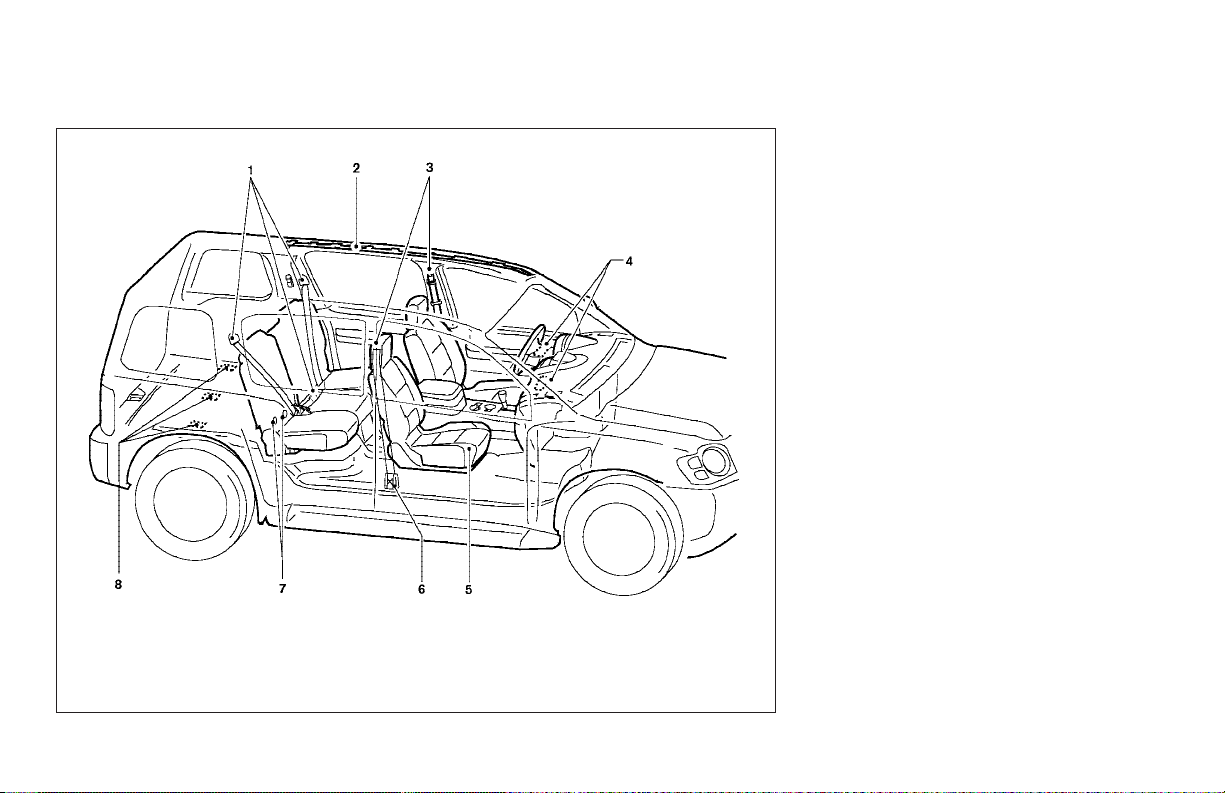
AIRBAGS, SEAT BELTS AND CHILD
RESTRAINTS
1. 2nd row seat belts (P. 1-21)
2. Supplemental curtain side-impact air
bags (if so equipped) (P. 1-8)
3. Front seat belts (P. 1-21)
4. Supplemental front impact air bags
(P.1-8)
5. Seats (P. 1-2)
6. Seat belt pretensioners (P. 1-18)
7. LATCH (Lower Anchors and Tethers for
CHildren) (P. 1-39)
8. Top tether strap anchor point locations
(P. 1-42)
See the page number indicated in parentheses for operating details.
0-2 Illustrated table of contents
LII0033
Page 9
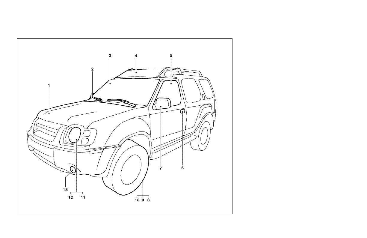
EXTERIOR FRONT
1. Engine hood (P. 3-9)
2. Windshield wiper and washer switch
(P. 2-18)
3. Windshield (P. 8-25)
4. Roof rack (P. 2-34)
5. Power windows (P. 2-37)
6. Door locks, keyfob, keys
(P. 3-2, 3-4, 3-2)
7. Mirrors (P. 3-13)
8. Tire pressure (P. 9-11)
9. Flat tire (P. 6-2)
10. Tire chains (P. 5-27)
11. Replacing bulbs (P. 8-32)
12. Headlight and turn signal switch
(P. 2-20)
13. Fog light switch (P. 2-22)
See the page number indicated in parentheses for operating details.
LII0032
Illustrated table of contents 0-3
Page 10
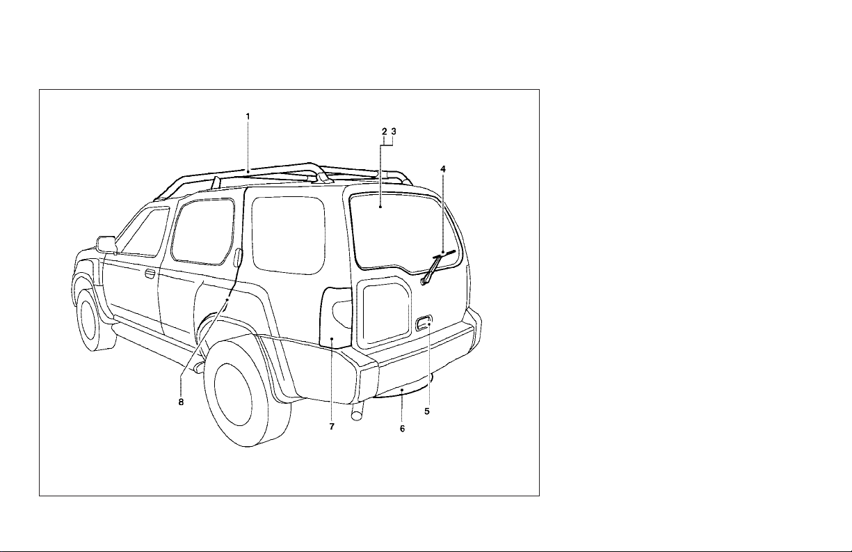
EXTERIOR REAR
1. Roof rack (P. 2-34)
2. Vehicle loading (P. 9-12)
3. Rear window defrost (P. 2-10)
4. Rear window washer (P.2-19)
5. Back door (P. 3-10)
6. Spare tire (P.6-2)
7. Replacing bulbs (P. 8-32)
8. Child safety rear door lock (P.3-4)
See the page number indicated in parentheses for operating details.
0-4 Illustrated table of contents
LII0031
Page 11
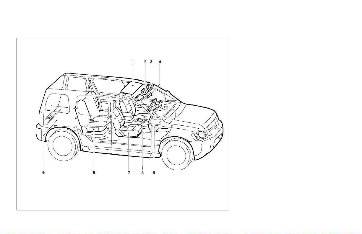
PASSENGER COMPARTMENT
1. Sunroof (if so equipped) (P. 2-40)
2. Map lights (P. 2-42)
3. Sun visors (P. 3-13)
4. Inside mirror (P.3-13)
5. Glove box (P. 2-30)
6. Cup holders (P. 2-29)
7. Front seats (P. 1-2)
8. Rear seats (P.1-4)
9. Storage (P. 2-27)
See the page number indicated in parentheses for operating details.
LII0034
Illustrated table of contents 0-5
Page 12
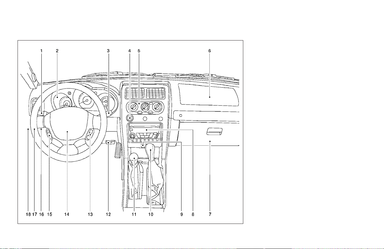
INSTRUMENT PANEL
0-6 Illustrated table of contents
WIC0641
1. Headlight/turn signal switch (P. 2-20)
2. Meters and gauges (P. 2-3)
3. Windshield wiper/washer switch
(P. 2-18)
4. Power outlet (P. 2-24)
5. Heater and air conditioner (P. 4-2)
6. Front passenger supplemental air bag
(P. 1-8)
7. Glove box (P. 2-30)
8. Audio system (P. 4-10)
9. Hazard warning flasher switch
(P. 2-23)
10. Automatic/manual selector lever
(P. 5-10)
11. Transfer case shift lever (if so
equipped) (P. 5-19)
12. Parking brake release lever (P. 5-16)
13. Cruise control main/set switch
(if so equipped) (P. 5-16)
14. Driver supplemental air bag/horn
(P. 1-8, P. 2-23)
15. Steering wheel switch for audio con-
trols (if so equipped) (P. 4-28)
16. Vehicle dynamic control (VDC) off
switch (if so equipped) (P. 2-24)
17. Instrument brightness control (P. 2-22)
18. Rear window wiper and washer switch
(if so equipped)(P. 2-19)
Page 13
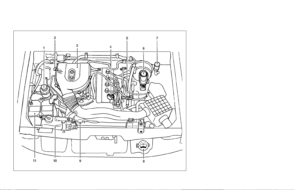
ENGINE COMPARTMENT CHECK
LOCATIONS
KA24DE engine
1. Power steering fluid reservoir (P. 8-15)
2. Automatic transmission fluid dipstick
(A/T model) (P. 8-14)
3. Air cleaner (P. 8-22)
4. Engine oil filler cap (P. 8-10)
5. Engine oil dipstick (P. 8-10)
6. Brake fluid reservoir (P. 8-16)
7. Clutch fluid reservoir (M/T model)
(P.8-16)
8. Windshield washer fluid reservoir
(P. 8-17)
9. Radiator cap (P. 8-9)
10. Engine coolant reservoir (P. 8-9)
11. Battery (P. 8-17)
See the page number indicated in parentheses for operating details.
WDI0087
Illustrated table of contents 0-7
Page 14
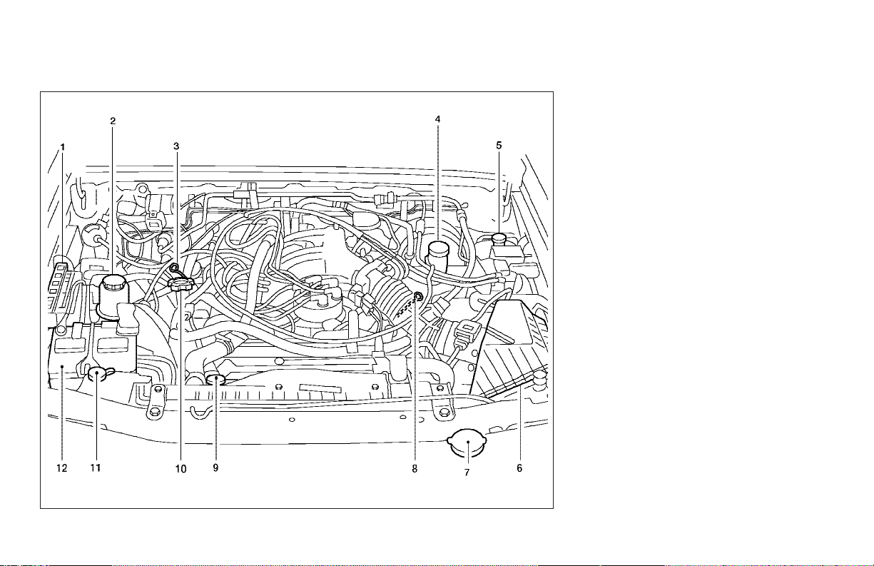
WDI0269
VG33E engine
1. Fuse/fusible link holder (P.8-30)
2. Power steering fluid reservoir (P. 8-15)
3. Automatic transmission fluid dipstick
(A/T model) (P. 8-14)
4. Brake fluid reservoir (P. 8-16)
5. Clutch fluid reservoir (M/T model)
(P. 8-16)
6. Air cleaner (P. 8-22)
7. Windshield washer fluid reservoir
(P. 8-17)
8. Engine oil dipstick (P. 8-10)
9. Radiator cap (P. 8-9)
10. Engine oil filler cap (P. 8-10)
11. Engine coolant reservoir (P. 8-9)
12. Battery (P. 8-17)
0-8 Illustrated table of contents
Page 15
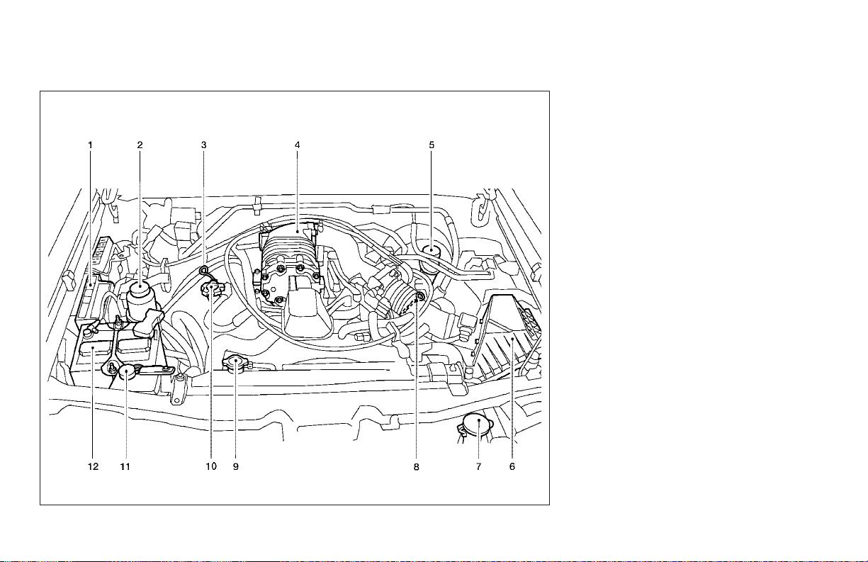
WDI0270
VG33ER engine
1. Fuse/fusible link holder (P.8-30)
2. Power steering fluid reservoir (P. 8-15)
3. Automatic transmission fluid dipstick
(A/T model) (P. 8-14)
4. Supercharger
5. Brake fluid reservoir (P. 8-16)
6. Air cleaner (P. 8-22)
7. Windshield washer fluid reservoir
(P. 8-17)
8. Engine oil dipstick (P. 8-10)
9. Radiator cap (P. 8-9)
10. Engine oil filler cap (P. 8-10)
11. Engine coolant reservoir (P. 8-9)
12. Battery (P. 8-17)
Illustrated table of contents 0-9
Page 16
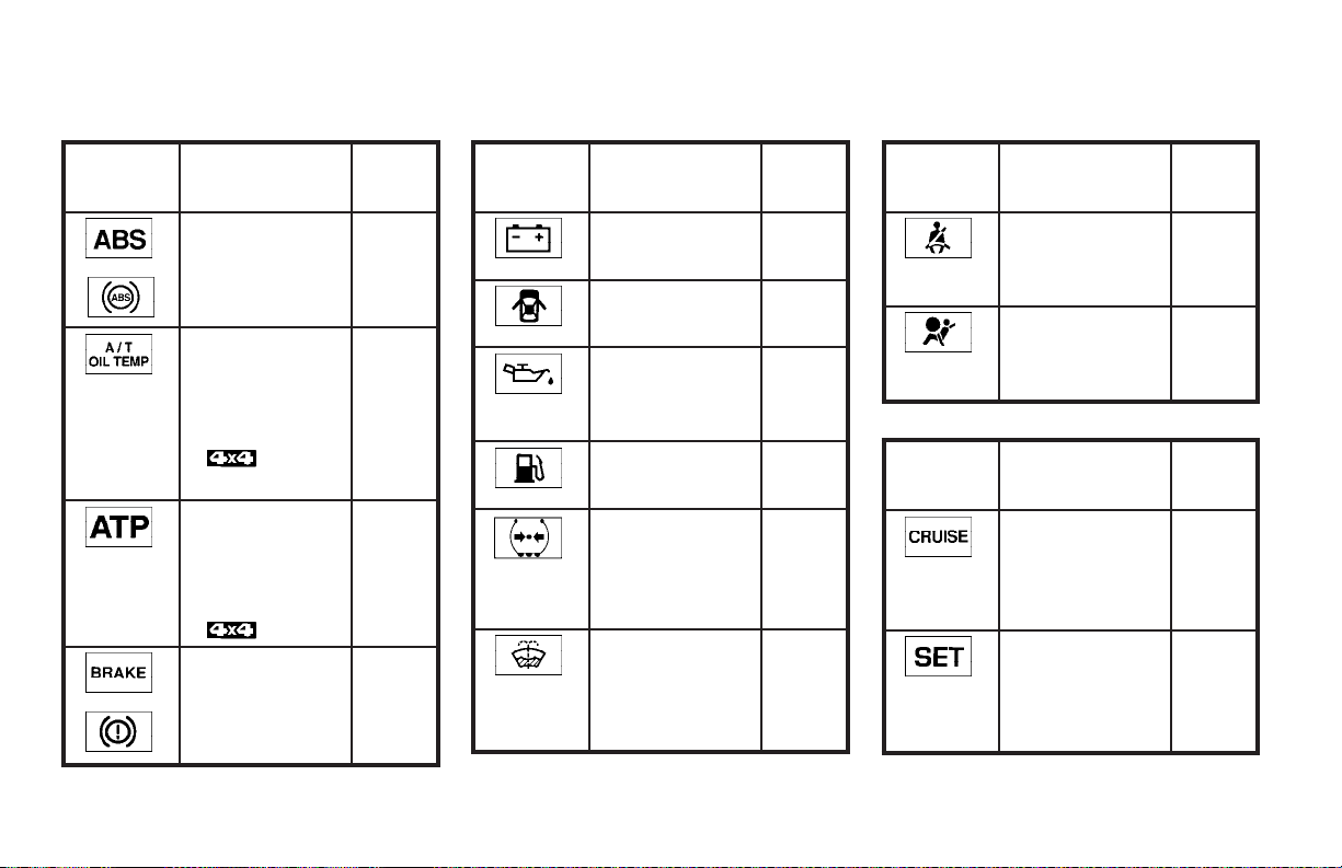
WARNING/INDICATOR LIGHTS
Warning
light
or
or
Name Page
Anti-lock brake
warning light
Automatic
transmission oil
temperature
warning light
(
model)
Automatic
transmission
park warning
light
(
Brake warning
light
model)
2-10
2-10
2-10
2-10
Warning
light
Name Page
Charge warning
light
Door open
warning light
Engine oil pressure warning
light
Low fuel warning light
Low tire pressure warning
light (if so
equipped)
Low windshield
washer fluid
warning light
(if so equipped)
2-11
2-11
2-11
2-11
2-11
2-12
Warning
light
Indicator
light
Name Page
Seat belt warning light and
chime
Supplemental
air bag warning
light
Name Page
Cruise main
switch indicator
light (if so
equipped)
Cruise set
switch indicator
light (if so
equipped)
2-12
2-13
2-13
2-13
0-10 Illustrated table of contents
Page 17
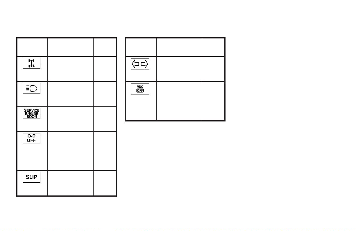
Indicator
light
Name Page
Indicator
light
Name Page
4-wheel drive
indicator light
(if so equipped)
High beam indicator light
(Blue)
Malfunction
indicator lamp
(MIL)
Overdrive off
indicator light
(automatic
transmission
only)
Slip indicator
light (if so
equipped)
2-13
2-13
2-14
2-14
2-14
Turn
signal/hazard
indicator lights
Vehicle dynamic control
off indicator
light (if so
equipped)
2-14
2-15
Illustrated table of contents 0-11
Page 18

MEMO
0-12 Illustrated table of contents
Page 19

1 Safety—Seats, seat belts and
supplemental air bags
Seats ............................................1-2
Front manual seat adjustment ....................1-2
Rear seat adjustment (Type A) ...................1-4
Rear seat adjustment (Type B) ...................1-6
Head restraint adjustment .......................1-8
Supplemental restraint system ......................1-8
Precautions on supplemental restraint
system ........................................1-8
Supplemental air bag warning labels.............1-19
Supplemental air bag warning light ..............1-19
Seat belts .......................................1-21
Precautions on seat belt usage..................1-21
Child safety...................................1-23
Pregnant women ..............................1-24
Injured persons................................1-24
Three-point type seat belt with retractor..........1-25
Two-point type seat belt without retractor
(center of rear seat)............................1-28
Seat belt extenders ............................1-29
Seat belt maintenance .........................1-30
Child restraints...................................1-30
Precautions on child restraints ..................1-30
Installation on rear seat center position...........1-32
Installation on rear seat outboard positions .......1-35
LATCH (Lower Anchors and Tethers for
CHildren) system..............................1-39
Top tether strap child restraint ..................1-41
Installation on front passenger seat ..............1-43
Page 20
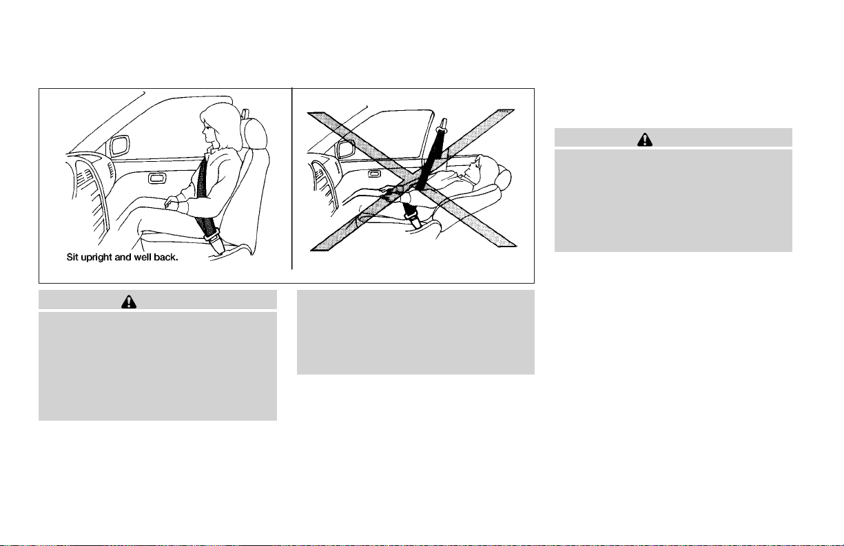
SEATS
WARNING
● Do not ride in a moving vehicle when
the seatback is reclined. This can be
dangerous. The shoulder belt will not
be against your body. In an accident,
you could be thrown into it and receive
neck or other serious injuries. You
could also slide under the lap belt and
receive serious internal injuries.
FRONT MANUAL SEAT
ADJUSTMENT
WARNING
● Do not adjust the driver’s seat while
driving so full attention may be given to
vehicle operation. The seat may move
suddenly and could cause loss of control of the vehicle.
● After adjustment,gently rockin theseat
to make sure it is securely locked.
ARS1152
● For the most effective protection when
the vehicle is in motion, the seat should
be upright. Always sit well back in the
seat and adjust the seat properly. See
“Precautions on Seat Belt Usage” later
in this section.
1-2 Safety—Seats, seat belts and supplemental air bags
Page 21
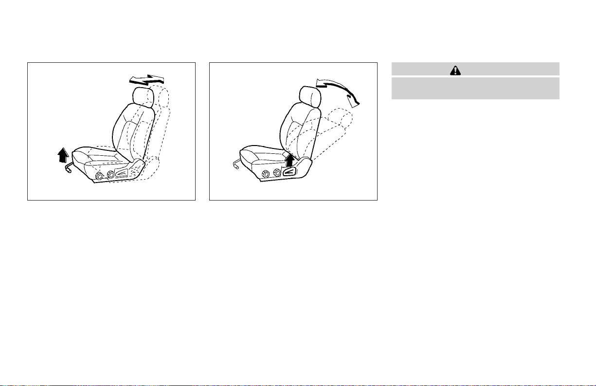
WRS0175 WRS0176
Forward and backward
Pull the lever up and hold it while you slide the
seat forwardor backward to the desiredposition.
Release the lever to lock the seat in position.
WARNING
After adjustment, gently rock in the seatto
make sure it is securely locked.
Reclining
Torecline the seatback, pull the lever up andlean
back. To bring the seatback forward, pull thelever
up and lean your body forward. Release the lever
to lock the seatback in position.
The reclining feature allows adjustment of the
seatback for occupants of different sizes for
added comfort and to help obtain proper seat
belt fit(see “Precautions on seat belt usage”later
in this section). Also, the seatback can be reclined to allow occupants to rest when the vehicle is stopped.
Safety—Seats, seat belts and supplemental air bags 1-3
Page 22
WRS0131 WRS0389 WRS0180
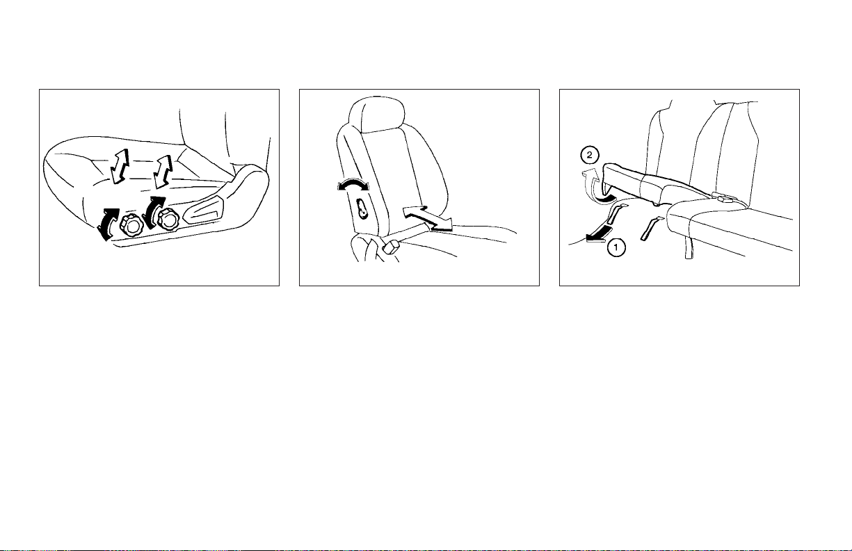
Seat lifter (if so equipped for driver’s
seat)
Turn either dial to adjust the angle and height of
the seat cushion to the desired position.
Lumbar support (if so equipped for
driver’s seat)
The lumbar support feature provides lower back
support to the driver. Move the lever forward or
backward to adjust the seat lumbar area.
1-4 Safety—Seats, seat belts and supplemental air bags
REAR SEAT ADJUSTMENT (Type A)
Folding
1
Pull outward on the 2straps at the bottom of
s
the seat cushions.
2
Lift the front of the seat cushion up and
s
remove the seat cushion. Store the seat
cushion in a secure place.
Page 23
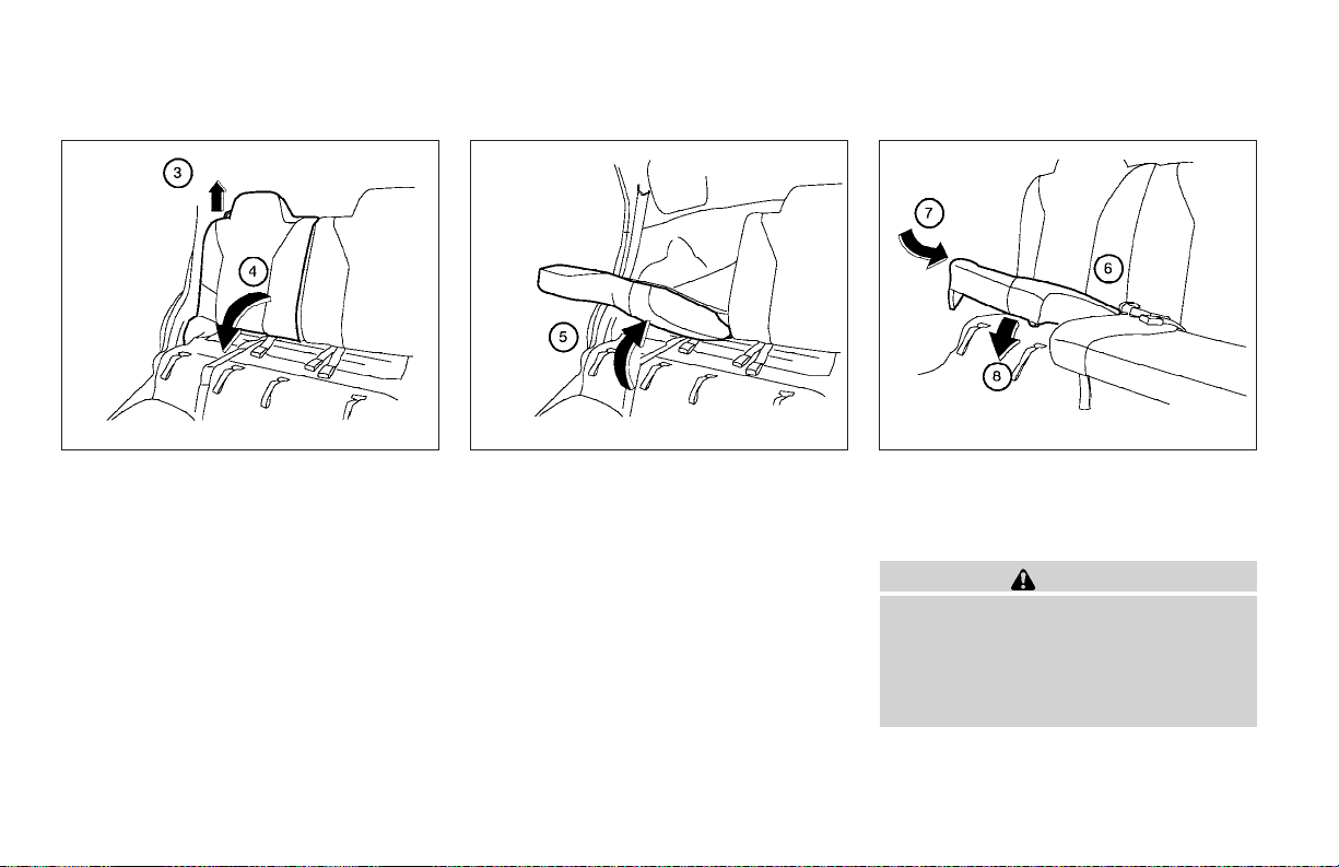
3
Pull the ring on top of the seatback up.
s
4
Fold down the seatback.
s
WRS0181 WRS0182 WRS0183
5
To return the rear seatback to a seating
s
position, push the seatback up until it
latches.
Safety—Seats, seat belts and supplemental air bags 1-5
6
Hold the seat belts above the seat cushion.
s
7
Slide the seat cushion back.
s
8
Push down the seat cushion until it latches.
s
WARNING
● Never allow anyone to ride in the cargo
area or on the rear seat when it is in the
fold-down position. Use of these areas
by passengers without proper restraints
could result in serious injury in an accident or sudden stop.
Page 24
● Do not allow people to ride in any area
of your vehicle that is not equipped with
seats and seat belts. Be sure everyone
in your vehicle is in a seat and using a
seat belt properly. Never ride in the rear
seat unless the seat bottom cushions
are in place and latched.
● Properly secure all cargo with ropes or
straps to help prevent it from sliding or
shifting. In a sudden stop or collision,
unsecured cargo could cause personal
injury.
● When returning the seatbacks to the
upright position, be certain they are
completely secured. If they are not completely secured in the latched position,
passengers may be injured in an accident or sudden stop.
WRS0184 WRS0185
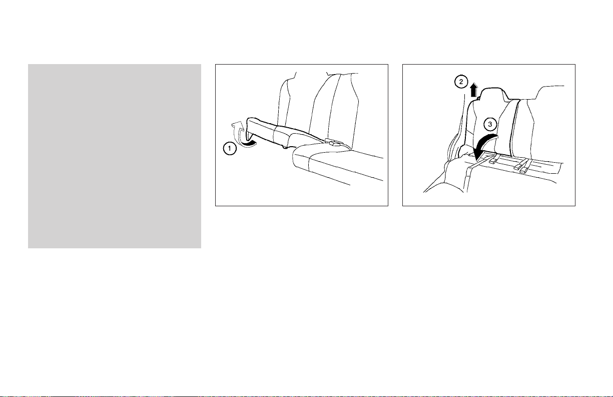
REAR SEAT ADJUSTMENT (Type B)
Folding
1
Lift the front of the seat cushion up and
s
remove the seat cushion. Store the seat
cushion in a secure place.
2
Pull the ring on top of the seatback up.
s
3
Fold down the seatback.
s
1-6 Safety—Seats, seat belts and supplemental air bags
Page 25
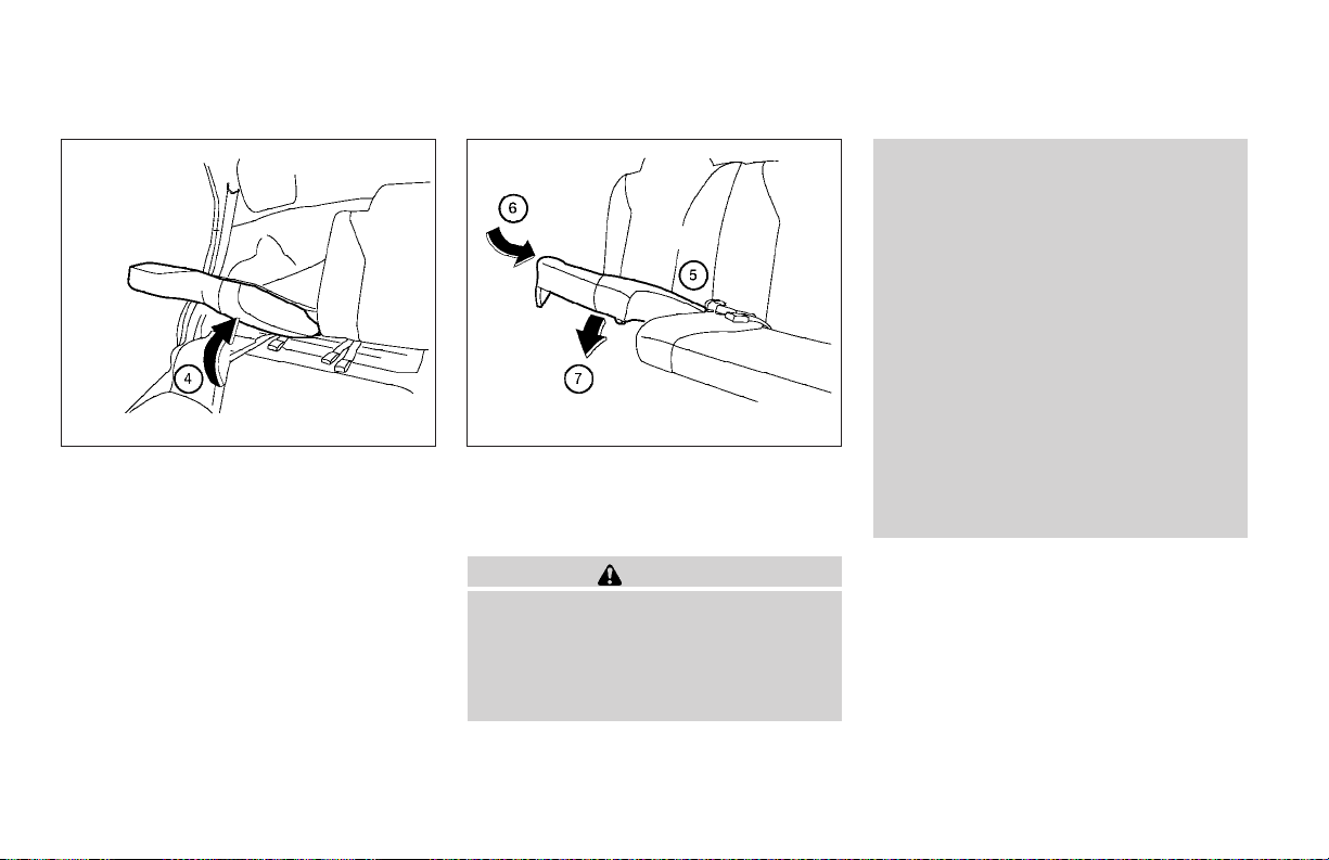
4
Toreturn the rear seat to the normal position,
s
push the seatback up until latches.
WRS0186 WRS0187
5
Hold the seat belts above the seat cushion.
s
6
Slide the seat cushion back.
s
7
Push down the seat cushion until it latches.
s
WARNING
● Never allow anyone to ride in the cargo
area or on the rear seat when it is in the
fold-down position. Use of these areas
by passengers without proper restraints
could result in serious injury in an accident or sudden stop.
● Do not allow people to ride in any area
of your vehicle that is not equipped with
seats and seat belts. Be sure everyone
in your vehicle is in a seat and using a
seat belt properly. Never ride in the rear
seat unless the seat bottom cushions
are in place and latched.
● Properly secure all cargo with ropes or
straps to help prevent it from sliding or
shifting. In a sudden stop or collision,
unsecured cargo could cause personal
injury.
● When returning the seatbacks to the
upright position, be certain they are
completely secured. If they are not completely secured in the latched position,
passengers may be injured in an accident or sudden stop.
Safety—Seats, seat belts and supplemental air bags 1-7
Page 26
WRS0133 WRS0134
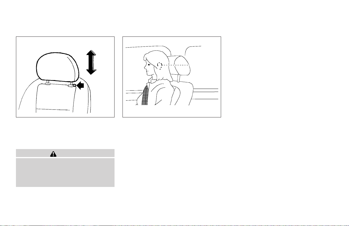
HEAD RESTRAINT ADJUSTMENT
To raise the head restraint, pull it up. To lower,
push and hold the lock knob and push the head
restraint down.
WARNING
Head restraints should be adjusted properly as they may provide significant protection against injury in an accident. Do
not remove them. Check the adjustment
after someone else uses the seat.
Adjust the head restraint so the center is level
with the center of your ears.
SUPPLEMENTAL RESTRAINT
SYSTEM
PRECAUTIONS ON
SUPPLEMENTAL RESTRAINT
SYSTEM
This Supplemental Restraint System (SRS) section contains important information concerning
the driver and passenger supplemental front air
bags and pre-tensioner seat belts.
Supplemental front impact air bag system:
This system can help cushion the impact force to
the head and chest of the driver and front passenger in certain frontal collisions.
Supplemental curtain side-impact air bag
system (if so equipped): This system can help
cushion the impact force to the head of occupants infront andrear outboard seating positions
in certainside impact collisions. The curtain sideimpact air bags are designedto inflate on the side
where the vehicle is impacted.
The supplemental air bags are designed to
supplement the crash protection provided by
the driver and front passenger seat belts and are
not a substitute for them. Seat belts should
always be correctly worn and the driver and front
passenger seated a suitable distance away from
the steering wheel and instrument panel. (See
“Seat belts” later in this section for instructions
and precautions on seat belt usage.)
1-8 Safety—Seats, seat belts and supplemental air bags
Page 27
The supplemental air bags operate only
when the ignition switch is in the ON or
START position.
After turning the ignition key to the ON
position, the supplemental air bag warning
light illuminates. The supplemental air bag
warning light will turn off after about 7
seconds if the system is operational.
WARNING
● The supplemental front air bags ordinarily will not inflate in the event of a
side impact, rear impact, rollover, or
lower severity frontal collision. Always
wear your seat belts to help reduce the
risk or severity of injury in various kinds
of accidents.
WRS0031
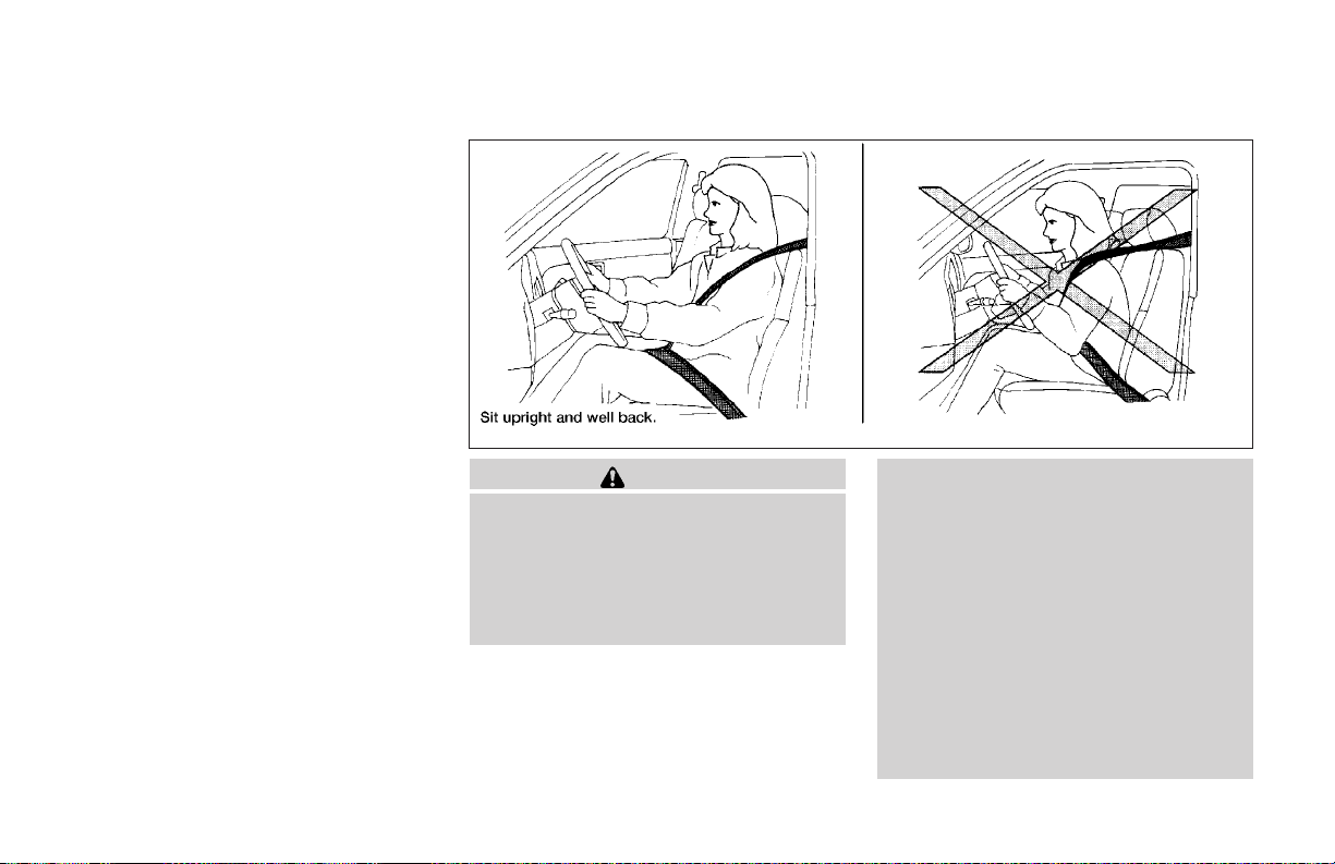
● The seat belts and the supplemental
front air bags are most effective when
you are sitting well back and upright in
the seat. The front air bags inflate with
great force. If you are unrestrained,
leaning forward, sitting sideways or out
of position in any way, you are at
greater risk of injury or death in a crash.
You may also receive serious or fatal
injuries from the supplemental front air
bag if you are up against it when it
inflates. Always sit back against the
seatback and as far away as practical
from the steering wheel or instrument
panel. Always use the seat belts.
Safety—Seats, seat belts and supplemental air bags 1-9
Page 28
● The driver and front passenger seat belt
buckles are equipped with sensors that
detect if the seat beltsare fastened. The
air bag system monitors the severity of
a collision andthen inflates the air bags
based on belt usage. Failure to properly
wear seat belts can increase the risk or
severity of injury in an accident.
● Keep hands on the outside of the steering wheel. Placing them inside the
steering wheel rim could increase the
risk that they are injured when the
supplemental front air bag inflates.
ARS1133
1-10 Safety—Seats, seat belts and supplemental air bags
Page 29
ARS1041 ARS1042 ARS1043
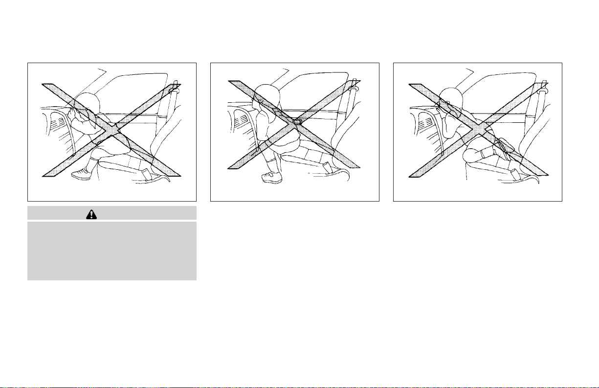
WARNING
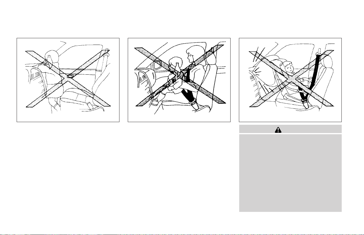
● Never let children ride unrestrained or
extend their hands or face out of the
window. Do not attempt to hold them in
your lap or arms. Some examples of
dangerous riding positions are shown
in the illustrations.
Safety—Seats, seat belts and supplemental air bags 1-11
Page 30
ARS1044 ARS1045 WRS0256
1-12 Safety—Seats, seat belts and supplemental air bags
WARNING
● Children may be severely injured or
killed when the supplemental front air
bags or curtain side-impact air bags
inflate if they are not properly restrained. Pre-teens and children should
be properly restrained inthe rearseat, if
possible.
● Never install a rear-facing child restraint in the front seat. An inflating
supplemental front air bag could seriously injureor kill your child. See “Child
restraints” later in this section for
details.
Page 31
SSS0101 WRS0236 SSS0159
WARNING
Supplemental curtain side impact air bag:
● The supplemental curtain side-impact
air bag ordinarily will not inflate in the
event of a frontal impact, rear impact,
rollover or lower severity side collision.
Always wear your seat belt to help reduce the risk or severity of injury in
various kinds of accidents.
WARNING
● The seat belts and the supplemental
curtain side-impact air bags are most
effective when you are sitting well back
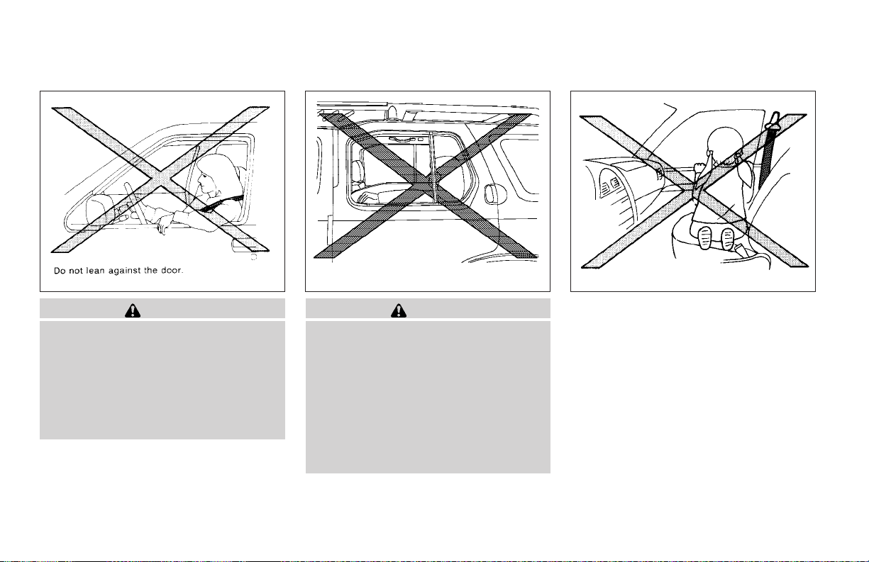
and upright in the seat. The curtain
side-impact air bag inflates with great
force. Do not allow anyone to place
their hand,leg or face near the side roof
rails or to extend their hand out of the
window or lean against the door. Some
examples of dangerous riding positions
are shown in the previous illustrations.
Safety—Seats, seat belts and supplemental air bags 1-13
Page 32
SSS0162
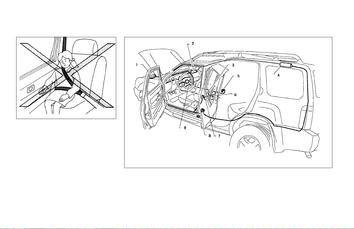
1. Crash zone sensor
2. Passenger supplemental air bag module
3. Passenger seat belt buckle switch
4. Side curtain air bag
5. Front seat belt pre-tensioner
1-14 Safety—Seats, seat belts and supplemental air bags
WRS0237
6. Driver seat belt buckle switch
7. Air bag diagnosis sensor unit
8. Front seat belt pre-tensioner
9. Driver supplemental air bag module
Page 33

Supplemental front air bag system
The driversupplemental front air bag is located in
the center of the steering wheel. The passenger
supplemental front air bag is mounted in the
dashboard above the glove box.
These systems are designed to meet optional
certification requirementsunder U.S.regulations.
They are also permitted in Canada. The optional
certification allows the front air bags to be designed to inflate somewhat less forcefully than
previously. However, all of the information,
cautions and warnings in this manual still
apply and must be followed.
The supplemental front air bag system is designed to inflate in higher severity frontal collisions, although it may inflate if the forces in another type of collision are similar to those of a
higher severity frontal impact. It may not inflate in
certain frontal collisions. Vehicle damage (or lack
of it) is not alwaysan indication of proper supplemental front air bag system operation.
The supplemental air bag system has dual stage
inflators for both the driver and passenger air
bags. The system monitors information from the
crash zone sensor, the diagnosis sensor unit and
seat belt buckle sensors that detect if the seat
belts are fastened. Inflator operation is based on
the severity of a collision and whether the seat
belts are being used. Only one front air bag may
inflate ina crash,depending on the crash severity
and whether the front occupants are belted or
unbelted. Thisdoes not indicate improper performance of the system. If you have any questions
about the performance of your air bag system,
please contact your NISSAN dealer.
When the supplemental front air bag inflates, a
fairly loud noise may be heard, followed by the
release of smoke. This smoke is not harmful and
does not indicate a fire. Care should be taken to
not inhale it, as it may cause irritation and choking. Those with a history of a breathing condition
should get fresh air promptly.
Supplemental front air bags, along with theuse of
seat belts, help to cushion the impact force on
the face and chest of the front occupants. They
can help save lives and reduce serious injuries.
However, an inflating front air bag may cause
facial abrasions or other injuries. Front air bags
do not provide restraint to the lower body.
Seat belts should be correctly worn and the
driver and passenger seated upright as far as
practical away from the steering wheel or instrument panel. The supplemental front air bags inflate quickly in order to help protect the front
occupants. Because of this, the force of the front
air bag inflating can increase the risk of injury if
the occupant is too close to, or is against, the
front air bag module during inflation.
Safety—Seats, seat belts and supplemental air bags 1-15
The front air bags deflate quickly after a collision.
The supplemental front air bags operate
only when the ignition switch is in the ON
or START position.
After turning the ignition key to the ON
position, the supplemental air bag warning
light illuminates. The supplemental air bag
warning light will turn off after about 7
seconds if the system is operational.
WARNING
● Do not place any objects on the steering wheel pad or on the instrument
panel. Also, do not place any objects
between any occupant and the steering
wheel or instrument panel. Such objects may become dangerous projectiles and cause injury if the supplemental front air bag inflates.
● Immediately after inflation, several
front air bag system components will be
hot. Do not touch them; you may severely burn yourself.
Page 34
● No unauthorized changes should be
made to any components or wiring of
the supplemental air bagsystem. Thisis
to prevent accidental inflation of the
supplemental air bag or damage to the
supplemental air bag system.
● Do not make unauthorized changes to
your vehicle’s electrical system, suspension system or front end structure.
This could affect proper operation of
the supplemental front air bag system.
● Tampering with the supplemental front
air bag system may result in serious
personal injury. Tampering includes
changes to the steering wheel and the
instrument panel assembly by placing
material over the steering wheel pad
and above the instrument panel or by
installing additional trim material
around the air bag system.
● Work on and around the supplemental
front air bag system should be done by
a NISSAN dealer. Installation of electrical equipment should also be done by a
NISSAN dealer. The Supplemental Restraint System (SRS) wiring should not
be modified or disconnected. Unauthorized electrical test equipment and
probing devices should not be used on
the air bag system.
● A cracked windshield should be replaced immediately by a qualified repair facility. A cracked windshield could
affect inflation of the supplemental air
bag system.
● The SRS wiring harness connectors are
yellow and orange for easy
identification.
When selling your vehicle, we request that you
inform the buyer about the supplemental front air
bag system and guide the buyer to the appropriate sections in this Owner’s Manual.
WRS0235
Supplemental curtain side-impact air
bag system (if so equipped)
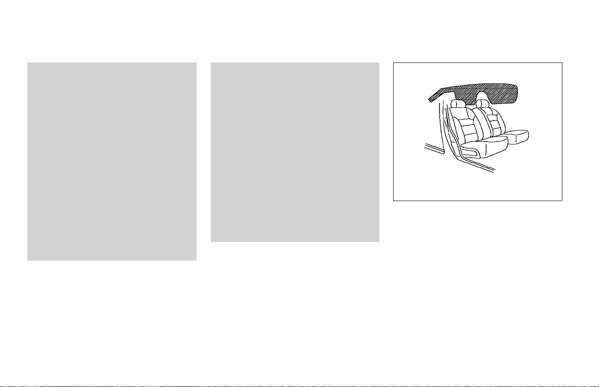
The supplemental curtain side-impact air bags
are located in the roof side rails. This system is
designed to meet voluntary guidelines to help
reduce the risk of injury to out-of-position occupants. However, all of the information, cau-
tions and warnings in this manual still apply and must be followed. The curtain side-
impact air bags are designed to inflate in higher
severity side collisions, although they may inflate
if the forces in anothertype of collision are similar
to thoseof a higher severity side impact. They are
1-16 Safety—Seats, seat belts and supplemental air bags
Page 35
designed to inflate on the side where the vehicle
is impacted. They may not inflate in certain side
collisions.
Vehicle damage (or lack of it) is not always an
indication of proper supplemental curtain sideimpact air bag operation.
When the supplemental curtain side-impact air
bags inflate, a fairly loud noise may be heard,
followed by release of smoke. This smoke is not
harmful and does not indicate a fire. Care should
be taken not to inhale it, as it may cause irritation
and choking. Those with a history of a breathing
condition should get fresh air promptly.
Supplemental curtain side-impact air bags help
to cushion the impact force to the head of occupants in the front and rear outboard seating positions. They can help save lives and reduce
serious injuries. However, an inflating curtain
side-impact airbag maycause abrasionsor other
injuries. Supplemental curtain side-impact air
bags do not provide restraint to the lower body.
Rear seat passengers should be seated as far
away aspractical fromthe doorfinishers andside
roof rails. The curtain side-impact air bag inflate
quickly in order to help protect the occupants.
Because of this, the force of the curtain sideimpact air bag inflating can increase the risk of
injury if the occupant is too close to,or is against,
these air bag modules during inflation. The curtain side-impact air bag will deflate quickly after
the collision is over.
The supplemental curtain side-impact air
bags operate only when the ignition switch
is in the ON or START position.
After turning the ignition key to the ON
position, the supplemental air bag warning
light illuminates. The supplemental air bag
warning light will turn off after about 7
seconds if the system is operational.
WARNING
● Right after inflation, several curtain
side-impact air bag system components will be hot. Do not touch them;
you may severely burn yourself.
● No unauthorized changes should be
made to any components or wiring of
the curtain side-impact air bag system.
This is to prevent accidental inflation of
the curtain side-impact air bag or damage to the curtain side-impact air bag
system.
Safety—Seats, seat belts and supplemental air bags 1-17
● Do not make unauthorized changes to
your vehicle’s electrical system, suspension system or side panel. This
could affect proper operation of the
supplemental curtain side-impact air
bag system.
● Work around and on the curtain sideimpact air bag system should be done
by a NISSAN dealer. Installation of electrical equipment should also be done by
a NISSAN dealer. The SRS wiring harnesses* should not be modified or disconnected. Unauthorized electrical test
equipment and probing devices should
not be used on the side air bag system.
* The SRS wiring harness connectors are
yellow and orange for easy identification.
When selling your vehicle, we request that you
inform the buyer about the supplemental side air
bag and curtain side-impact air bag system and
guide the buyer to the appropriate sectionsin this
Owner’s Manual.
Page 36
Pre-tensioner seat belt system (front
seats)
WARNING
● The pre-tensioner seat belt cannot be
reused after activation. It must be replaced together with the retractor and
buckle as a unit.
● If the vehicle becomes involved in a
frontal collisionbut the pre-tensioner is
not activated, be sure to have the pretensioner system checked and, if necessary, replaced by your NISSAN
dealer.
● No unauthorized changes should be
made to any components or wiring of
the pre-tensioner seat belt system. This
is to prevent accidental activation of
the pre-tensioner seat belt or damage
to the pre-tensioner seat belt operation.
Tampering with the pre-tensioner seat
belt system may result in serious personal injury.
● Work around and on the pre-tensioner
system should be done by a NISSAN
dealer. Installation of electrical equipment should also be done by a NISSAN
dealer. Unauthorized electrical test
equipment and probing devices should
not be used on the pre-tensioner seat
belt system.
● If you need to dispose of the pretensioner or scrapthe vehicle,contact a
NISSAN dealer. Correct pre-tensioner
disposal procedures are set forth in the
appropriate NISSAN Service Manual.
Incorrect disposal procedures could
cause personal injury.
The front seat pre-tensioner seat belt system
activates inconjunction with the supplemental air
bag systems. Working with the seat belt retractor, it helps tighten the seat belt when the vehicle
becomes involved in certain types of collisions,
helping to restrain front seat occupants.
The pre-tensioner is encased with the seat belt’s
retractor. These seat belts are used the same as
conventional seat belts.
When the pre-tensioner seat belt activates,
smoke is released and a loud noisemay beheard.
This smokeis not harmful and does not indicate a
fire. Care shouldbe takennot to inhaleit, asit may
1-18 Safety—Seats, seat belts and supplemental air bags
cause irritation and choking. Those with a history
of a breathing condition should get fresh air
promptly.
If any abnormality occurs in the pre-tensioner
system, the supplemental air bag warning
light
tion key is turned tothe ON or STARTposition. In
this case, the pre-tensioner seat belt will not
function properly. They must be checked and
repaired. Take your vehicle to the nearest
NISSAN dealer.
When selling your vehicle, we request that you
inform the buyer about thepre-tensioner seatbelt
system and guide the buyer to the appropriate
sections in this Owner’s Manual.
will flash intermittently after the igni-
Page 37
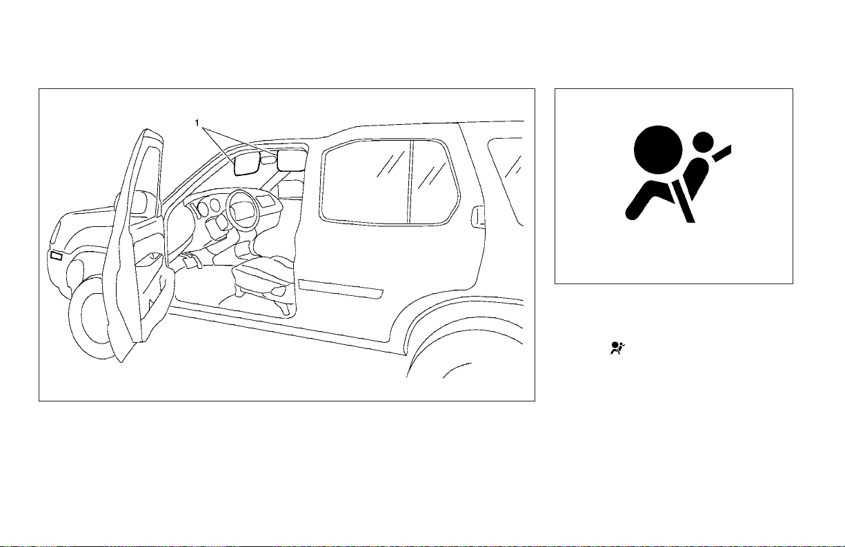
1. SRS Air Bag Warning Labels
WRS0424
SUPPLEMENTAL AIR BAG
WARNING LABELS
Warning labels about the supplemental front air
bag system are placed in the vehicle as shown in
the illustration.
Safety—Seats, seat belts and supplemental air bags 1-19
LRS0100
SUPPLEMENTAL AIR BAG
WARNING LIGHT
The supplemental air bag warning light,
displaying
tors the circuits of the supplemental front air bag,
supplemental curtain side-impact air bag (if so
equipped) and pre-tensioner seat belt systems.
The circuits monitored by the supplemental air
bag warning light are the diagnosis sensor unit,
crash zone sensor, supplemental front air bag
modules, supplemental curtain side-impact air
bag modules (if so equipped), pre-tensionerseat
belts and all related wiring.
in the instrument panel, moni-
Page 38
When the ignition key is in the ON or START
position, the supplemental air bag warning light
illuminates for about 7 seconds and then turns
off. This means the system is operational.
If any of the following system conditions occur,
the supplementalfront airbag, supplemental curtain side-impact air bag and pre-tensioner seat
belt systems need servicing:
● The supplemental air bag warning light remains on after approximately 7 seconds.
● The supplemental air bag warning light
flashes intermittently.
● The supplemental air bag warning light does
not come on at all.
Under these conditions, the Supplemental Restraint System (supplemental front air bag,
supplemental curtain side-impact air bag or pretensioner seat belt systems) may not operate
properly. It must be checked and repaired. Take
your vehicle to the nearest NISSAN dealer.
WARNING
If the supplemental air bag warning light
is on, it could mean that the supplemental
front air bag or pre-tensioner seat belt
systems will notoperate in an accident. To
help avoid injury to yourself or others,
have your vehicle checked by a NISSAN
dealer as soon as possible.
Repair and replacement procedure
The supplemental front air bags, supplemental
curtain side-impact air bags (if so equipped) and
pre-tensioner seat belts are designed to inflate
on a one-time-only basis. As a reminder, unless it
is damaged, the supplemental air bag warning
light remains illuminated after inflation has occurred. Repair and replacement of these supplemental air bag systems should be done only by a
NISSAN dealer.
When maintenance work is required on the vehicle, the supplemental front air bags, supplemental curtain side-impact air bags, pretensioner seat belts and related parts should be
pointed out to the person performing the maintenance. The ignition key should always be in the
LOCK position when working under the hood or
inside the vehicle.
WARNING
● Once a supplemental front air bag or
supplemental curtain side-impact air
bag has inflated,the airbag module will
not function again and must be replaced. Additionally, if any of the
supplemental front air bags inflate, the
activated pre-tensioner seat belts must
also be replaced. The air bag module
and pre-tensioner seat belt system
should be replaced by a NISSAN dealer.
The air bag module and pre-tensioner
seat belt system cannot be repaired.
● The supplemental front air bag and curtain side-impact air bag systems, and
the pre-tensioner seat belt system
should be inspected by a NISSAN
dealer if there is any damage to the
front end or side portion of the vehicle.
● If you need to dispose of the supplemental air bag, pre-tensioner seat belt
system or scrap the vehicle, contact a
NISSAN dealer. Correct supplemental
air bag and pre-tensioner seat belt system disposal procedures are set forth in
the appropriate NISSAN Service
Manual. Incorrect disposal procedures
could cause personal injury.
1-20 Safety—Seats, seat belts and supplemental air bags
Page 39
SEAT BELTS
PRECAUTIONS ON SEAT BELT
USAGE
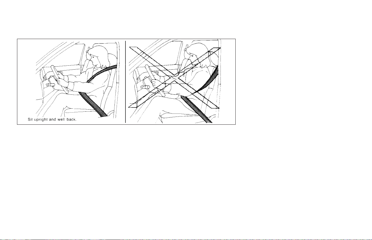
If you are wearing your seat belt properly adjusted, and you are sitting upright and well back
in your seat, your chances of being injured or
killed in an accident and/or the severity of injury
may be greatly reduced. NISSAN strongly encourages you and all of your passengers to
buckle up every time you drive, even if your seating position includes a supplemental air bag.
Most U.S. states and Canadian provinces
or territories specify that seat belts beworn
at all times when a vehicle is being driven.
SSS0136
Safety—Seats, seat belts and supplemental air bags 1-21
Page 40
WARNING
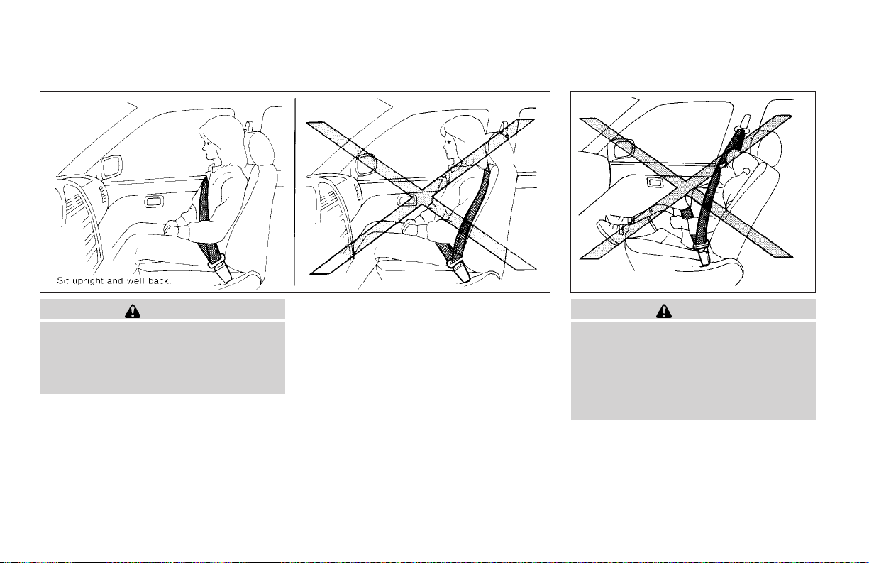
● Every person who drives or rides in this
vehicle should use a seat belt at all
times. Children should be properly restrained in the rear seat and, if appropriate, in a child restraint.
1-22 Safety—Seats, seat belts and supplemental air bags
SSS0134 SSS0016
WARNING
● The seat belt should be properly adjusted to a snug fit. Failure to do so may
reduce the effectiveness of the entire
restraint system and increase the
chance or severity of injury in an accident. Serious injury or death can occur
if the seat belt is not worn properly.
Page 41
SSS0014
WARNING
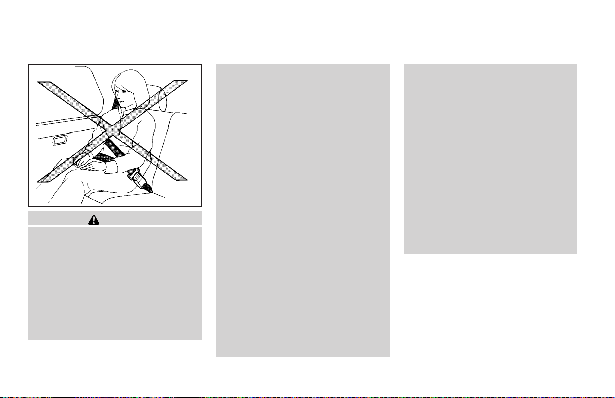
● Always route the shoulder belt over
your shoulder and across your chest.
Never run the belt behind your back,
under your armor across your neck. The
belt should be away from your face and
neck, but not falling off your shoulder.
● Position the lap belt as low and snug as
possible AROUND THE HIPS, NOT THE
WAIST. A lap belt worn too high could
increase the risk of internal injuries in
an accident.
● Be sure the seat belt tongue is securely
fastened to the proper buckle.
● Do not wear the seat belt inside out or
twisted. Doing so may reduce its
effectiveness.
● Do not allow more than one person to
use the same seat belt.
● Never carry more people in the vehicle
than there are seat belts.
● Never allow anyone to ride in the cargo
area while the vehicle is in motion. It
does not contain seat belts. It is not
designed for passengers. They could be
injured in sudden braking or a collision.
● If the seat belt warning light glows continuously while the ignition is turned
ON with all doors closed and all seat
belts fastened, it may indicate a malfunction in the system. Have the system
checked by a NISSAN dealer.
● Once the pre-tensioner seat belt has
activated, it cannot be reused and must
be replaced together with the retractor.
See your NISSAN dealer.
● Removal and installation of the pretensioner seat belt system components
should be done by a NISSAN dealer.
Safety—Seats, seat belts and supplemental air bags 1-23
● All seat belt assemblies, including retractors and attaching hardware,
should be inspected after any collision
by a NISSAN dealer. NISSAN recommends that all seat belt assemblies in
use during a collision be replaced unless the collision was minor and the
belts show no damage and continue to
operate properly. Seat belt assemblies
not in use during a collision should also
be inspected and replaced if either
damage orimproper operation is noted.
● All child restraints and attaching hardware should be inspected after any collision. Always follow the restraint
manufacturer’s inspection instructions
and replacement recommendations.
The child restraints should be replaced
if they are damaged.
CHILD SAFETY
Children need adults to help protect them.
They need to be properly restrained.
The proper restraint depends on the child’s size.
Generally, infants up to about 1 year and less
than 20 pounds (9 kg) should be placed in rear
facing child restraints. Front facing child restraints are available for children who outgrow
rear facing child restraints.
Page 42
WARNING
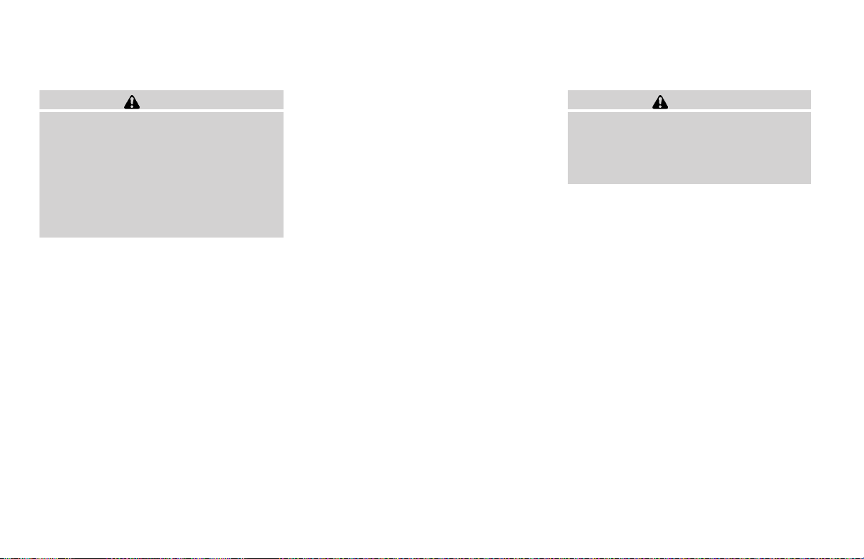
Infants and children need special protection. The vehicle’s seat belts may not fit
them properly. The shoulder belt may
come too close to the face or neck. The
lap belt may not fit over their small hip
bones. In an accident, an improperly fitting seat belt could cause serious or fatal
injury. Always use appropriate child
restraints.
All U.S. states and Canadian provinces or territories require the use of approved child restraints
for infants and small children. See “Child Restraints” later in this section.
In addition, there are many types of child restraints available for larger children which should
be used for maximum protection.
NISSAN recommends that all pre-teens
and children be restrained in the rear seat.
According to accident statistics, children
are safer when properly restrained in the
rear seat than in the front seat. This is
especially important because your vehicle
has a supplemental restraint system (Air
bag system) for the front passenger. See
“Supplemental restraint system” earlier in
this section.
Infants and small children
NISSAN recommends that infants and small children be placed in childrestraints thatcomply with
Federal Motor Vehicle Safety Standards or Canadian Motor Vehicle Safety Standards. You
should choose a child restraint that fits your vehicle and always follow the manufacturer’s instructions for installation and use.
Larger children
Children who are too large for child restraints
should beseated andrestrained by the seat belts
which are provided.
If the child’s seating position has a shoulder belt
that fits close to the face or neck, the use of a
booster seat (commercially available) may help
overcome this. The booster seat should raise the
child so that the shoulder belt is properly positioned across the top, middle portion of the
shoulder and the lap belt is low on the hips. The
booster seat should fit the vehicle seat and have
a label certifying that it complies with Federal
Motor Vehicle SafetyStandards or Canadian Motor Vehicle Safety Standards. Once the child has
grown sothe shoulder belt is no longer on or near
the face and neck, use the shoulder belt without
the booster seat.
WARNING
Never let a child stand or kneel on any
seat and do not allow a child in the cargo
areas while the vehicle is moving. The
child could beseriously injured or killed in
an accident or sudden stop.
PREGNANT WOMEN
NISSAN recommends that pregnant women use
seat belts. The seat belt should be worn snug,
and always position the lap belt as low as possible around the hips, not the waist. Place the
shoulder belt over your shoulder and across your
chest. Never run the lap/shoulder belt over your
abdominal area. Contact your doctor for specific
recommendations.
INJURED PERSONS
NISSAN recommends that injured persons use
seat belts. Check with your doctor for specific
recommendations.
1-24 Safety—Seats, seat belts and supplemental air bags
Page 43
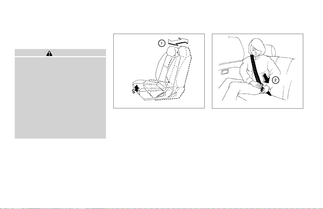
THREE-POINT TYPE SEAT BELT
WITH RETRACTOR
WARNING
● Every person who drives or rides in this
vehicle should use a seat belt at all
times.
● Do not ride in a moving vehicle when
the seatback is reclined. This can be
dangerous. The shoulder belt will not
be against your body. In an accident,
you could be thrown into it and receive
neck or other serious injuries. You
could also slide under the lap belt and
receive serious internal injuries.
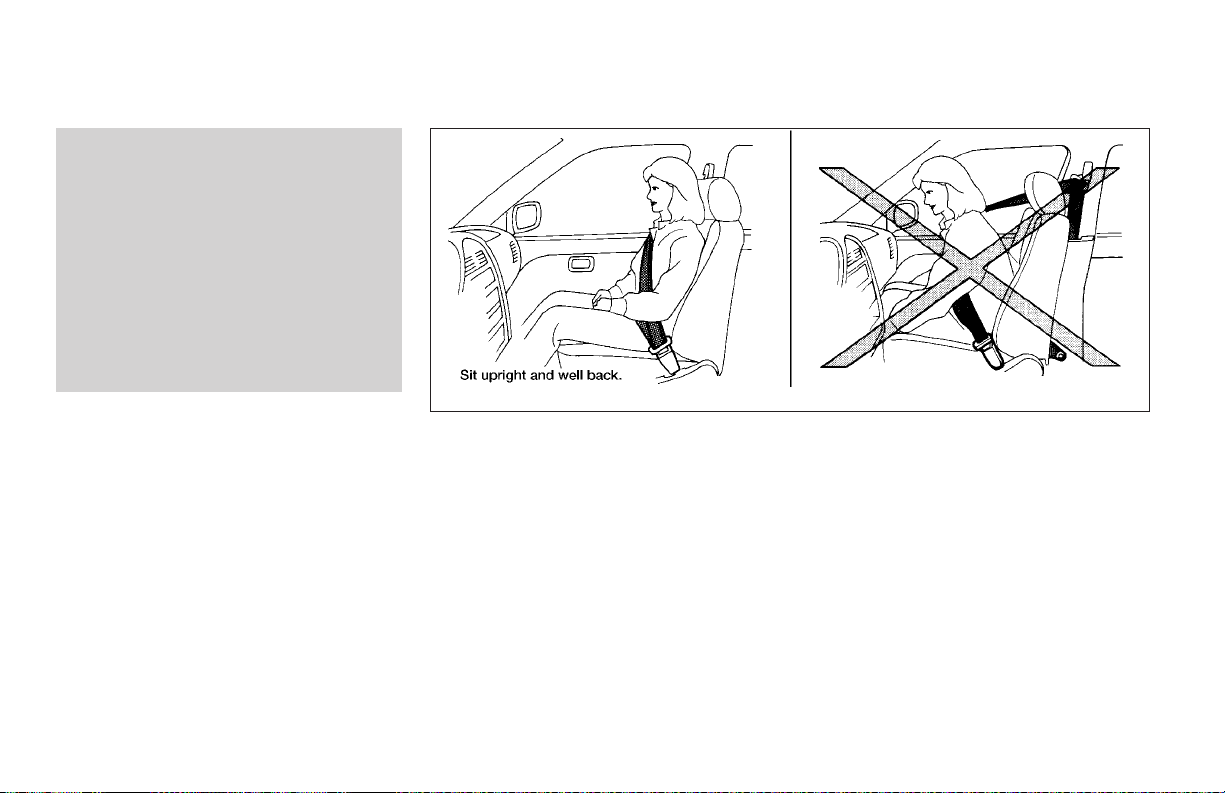
● For the most effective protection when
the vehicle is in motion, the seat should
be upright. Always sit well back in the
seat and adjust the seat belt properly.
Manual front seat shown
Fastening the seat belts
1
Adjust the seat. See “Seats” earlier in this
s
section.
WRS0174
WRS0137
2
Slowly pull the seat belt out of the retractor
s
and insert the tongue into the buckle until
you hear and feel the latch engage.
The retractor is designed to lock during a
sudden stop or on impact. A slow pulling
motion permits the seat belt to move, and
allows you some freedom of movement in
the seat.
Safety—Seats, seat belts and supplemental air bags 1-25
Page 44
emergency locking mode. See “Child restraints”
later in this section for more information.
The automatic locking mode should be
used only for child restraint installation.
During normal seat belt use by a passenger, the locking mode should not be activated. If it is activated it may cause uncomfortable seat belt tension.
When fastening the seat belts, be certain
that the seatbacks are completely secured in the latched position. If they are
WRS0138 WRS0139
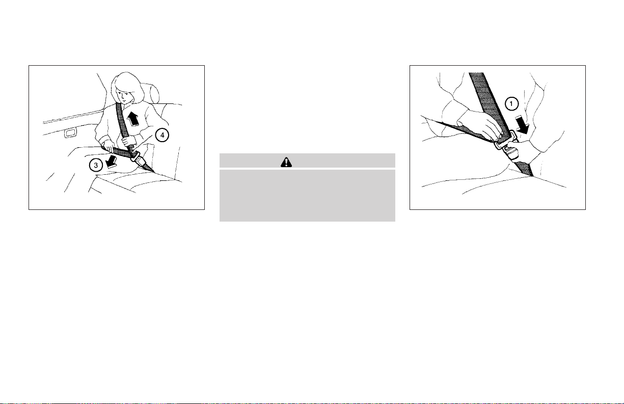
3
Position the lap belt portion low and snug
s
on the hips as shown.
4
Pull the shoulder belt portion toward the
s
retractor to take up extra slack. Be sure the
shoulder belt is routed over your shoulder
and across your chest.
The front passenger seat belt and the rear threepoint seat belts have a cinching mechanism for
child restraint installation. It is referred to as the
automatic locking mode.
When automatic locking mode is activated the
seat belt cannot be extended again until the seat
belt tongue is detached from the buckle and fully
retracted. Once retracted, the seat belt is in the
not completely secured, passengers may
be injured in an accident or sudden stop.
1-26 Safety—Seats, seat belts and supplemental air bags
WARNING
Unfastening the seat belts
1
Tounfasten the seatbelt, pressthe button on
s
the buckle. The seat belt automatically retracts.
Checking seat belt operation
Seat belt retractors are designed to lock seat belt
movement by two separate methods:
● When the seat belt is pulled quickly from the
retractor.
● When the vehicle slows down rapidly.
Page 45
To increase your confidence in the seat belts,
check the operation as follows.
● Grasp the shoulder belt and pull forward
quickly. The retractor should lock and restrict further belt movement.
If the retractor does not lock during this check or
if you have any questions about seat belt operation, see a NISSAN dealer.
WRS0189
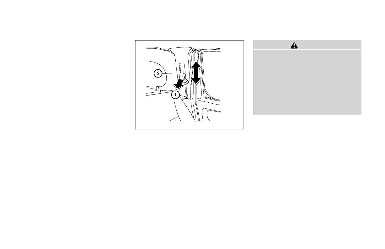
Shoulder belt height adjustment (Front
seats)
The shoulder belt anchor height should be adjusted to the position best for you. (See “Precautions on seat belt usage” earlier in this section.)
To adjust, pull out the adjustment button
move the shoulder belt anchor to the desired
position
the shoulder. The belt should be away from your
face and neck, but not falling off your shoulder.
Release the adjustment button to lock the shoulder belt anchor into position.
2
, so the belt passes over the center of
s
s
1
and
WARNING
● After adjustment, release the adjustment button and try to move the shoulder belt anchor up and down to make
sure it is securely fixed in position.
● The shoulder belt anchor height should
be adjusted to the position best for you.
Failure to do so may reduce the effectiveness of the entire restraint system
and increase the chance or severity of
injury in an accident.
Safety—Seats, seat belts and supplemental air bags 1-27
Page 46
WRS0190 WRS0191 WRS0192
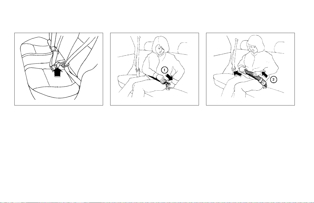
TWO-POINT TYPE SEAT BELT
WITHOUT RETRACTOR (center of
rear seat)
Fastening the belts
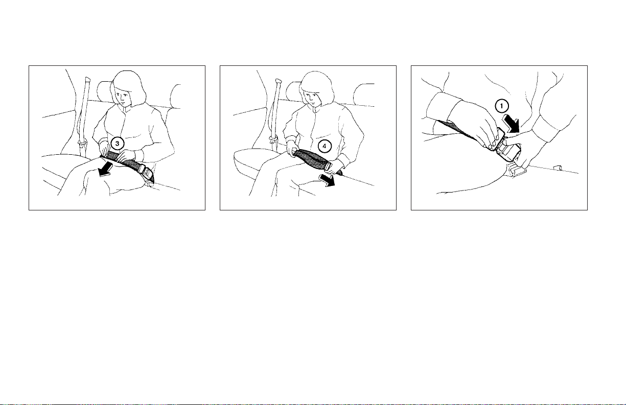
1. Insert the tongue into the buckle until you
hear and feel the latch engage.
1-28 Safety—Seats, seat belts and supplemental air bags
2. Tighten the belt by pullingthe free end of the
belt away from the tongue.
Page 47
WRS0193 WRS0194 WRS0201
3. Position the lap belt low and snug on the
hips as illustrated.
4. Loosen the belt by holding the tongue at a
right angle to the belt, then pull on the belt.
Safety—Seats, seat belts and supplemental air bags 1-29
Unfastening the seat belts
To unfasten the seat belt, press the button the
buckle.
SEAT BELT EXTENDERS
If, because of body size or driving position, it is
not possible to properly fit the lap-shoulder belt
and fasten it, an extender is available which is
compatible with the installed seat belts. The extender adds approximately 8 inches (200 mm) of
length and may be used for either the driver or
front passenger seating position. See a NISSAN
dealer for assistance if an extender is required.
Page 48
CHILD RESTRAINTS
WARNING
● Only NISSAN seat belt extenders, made
by the same company which made the
original equipment seat belts, should
be used with NISSAN seat belts.
● Adults and children who can use the
standard seat belt should not use an
extender. Such unnecessary use could
result in serious personal injury in the
event of an accident.
● Never use seat belt extenders to install
child restraints. If the child restraint is
not secured properly, the child could be
seriously injured in a collision or a sudden stop.
● Periodically check to see that the seat
belt andthe metal components, such as
buckles, tongues, retractors, flexible wires
and anchors, work properly. If loose parts,
deterioration, cuts or other damage on the
webbing is found, the entire seat belt assembly should be replaced.
SEAT BELT MAINTENANCE
● To clean the seat belt webbing, apply a
mild soap solution or any solution recommended for cleaning upholstery or carpet.
Then wipe with a cloth and allow the seat
belts to dry in the shade. Do not allow the
seat belts to retract until they are completely
dry.
● If dirt builds up in the shoulder belt
guide of the seat belt anchors, the seat
belts may retract slowly. Wipe the shoulder
belt guide with a clean, dry cloth.
1-30 Safety—Seats, seat belts and supplemental air bags
ARS1098
PRECAUTIONS ON CHILD
RESTRAINTS
WARNING
● Infants and small children should always be placed in an appropriate child
restraint while riding in the vehicle.
Failure to use a child restraint can result in serious injury or death.
Page 49
WRS0256
WARNING
● Infants and small children should never
be carried on your lap. It is not possible
for even thestrongest adultto resist the
forces of a severe accident. The child
could be crushed between the adult and
parts of the vehicle. Also, do not put the
same seat belt around both your child
and yourself.
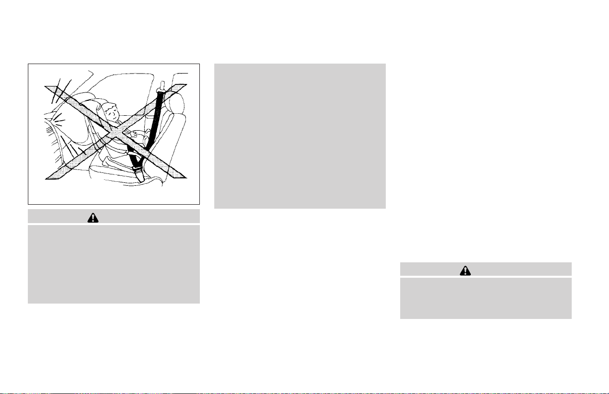
● Never install a rear-facing child restraint in the front seat. An inflating
supplemental front air bag could seriously injure or kill your child. A rearfacing child restraint must only be used
in the rear seat.
● NISSAN recommends that the child restraint be installed in the rear seat. According to accident statistics, children
are safer when properly restrained in
the rear seat than in the front seat.
● An improperly installed child restraint
could lead to serious injury or death in
an accident.
In general, child restraints are designed to be
installed with a lap belt or the lap portion of a
three-point type seat belt. Inaddition, this vehicle
is equipped with a universal child restraint lower
anchor system, referred to as the LATCH (Lower
Anchors andTethersfor CHildren)system. Some
child restraints include two rigid or webbingmounted attachments that can be connected to
these loweranchors. For details, see the “LATCH
(Lower Anchors and Tethers for CHildren) system” later in this section.
Child restraints for infants and small children of
various sizes are offered by several manufacturers. When selecting any child restraint, keep the
following points in mind:
Safety—Seats, seat belts and supplemental air bags 1-31
● Choose onlya restraintwith alabel certifying
that it complies with Federal Motor Vehicle
Safety Standard 213 or Canadian Motor
Vehicle Safety Standard 213.
● Check thechild restraint in your vehicleto be
sure it is compatible with the vehicle’s seat
and seat belt system.
● If the child restraint is compatible with your
vehicle, place your child in the child restraint
and check the various adjustments to be
sure the child restraint is compatible with
your child. Always follow all recommended
procedures.
All U.S. states and provinces of Canada
require that infants and small children be
restrained in an approved child restraint at
all times while the vehicle is being operated.
WARNING
● Improper use of a child restraint can
increase the risk or severity of injury for
both the child and other occupants of
the vehicle.
Page 50
● Follow all of the child restraint manufacturer’s instructions for installation
and use. When purchasing a child restraint, be sure to select one which will
fit your child and vehicle. It may not be
possible to properly install some types
of child restraints in your vehicle.
● If the child restraint is not anchored
properly, the risk of a child being injured in a collision or a sudden stop
greatly increases.
● Adjustable seatbacks should be positioned to fit the child restraint, but as
upright as possible.
● After attaching the child restraint, test it
before you place the child in it. Push it
from side to side. Try to tug it forward
and check to see if the belt holds the
restraint in place. The child restraint
should not move more than 1 inch (25
mm). If the restraint is not secure,
tighten the belt as necessary, or put the
restraint in another seat and test it
again.
● For a front-facing child restraint, if the
seat position where it is installed has a
three-point type lap/shoulder belt,
check to make sure the shoulder belt
does not go in front of thechild’s face or
neck. If it does, put the shoulder belt
behind the child restraint. If you must
install a front-facing child restraint in
the front seat, see “Installation on front
passenger seat” later in this section.
● When your child restraint is not in use,
keep it secured with a seat belt to prevent it from being thrown around in
case of a sudden stop or accident.
CAUTION
Remember that a child restraint left in a
closed vehicle can become very hot.
Check the seating surface and buckles
before placing your child in the child
restraint.
INSTALLATION ON REAR SEAT
CENTER POSITION
WRS0263
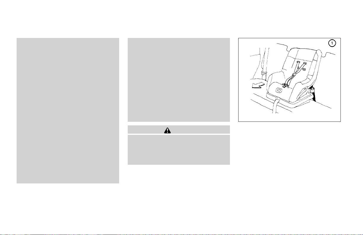
Front Facing — step 1
Front facing
When you install a child restraint in the rear
center seat, follow these steps:
1. Position the child restraint on the seat as
illustrated. Always follow the restraint manufacturer’s instructions.
1-32 Safety—Seats, seat belts and supplemental air bags
Page 51
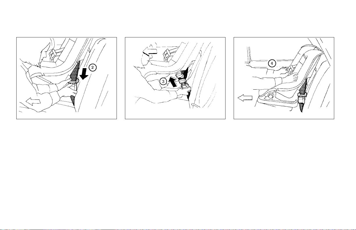
WRS0250
Front Facing — step 2
2. Route the seat belt tongue through the child
restraint andinsert it into the buckle until you
hear and feel the latch engage.
Be sure to follow the child restraint manufacturer’s instructions for belt routing.
WRS0264
Front Facing — step 3
3. Remove all slack in the lap belt for a very
tight fit by pulling forcefully on the lap belt
adjustment.
Safety—Seats, seat belts and supplemental air bags 1-33
WRS0265
Front Facing — step 4
4. Before placing the child in the child restraint,
use force to tilt the child restraint from side
to side, and tug it forward to make sure it is
securely in place. It should not move more
than 1 inch (25mm).
5. If it is not secure,try to tighten the belt again,
or put the restraint in another seat.
6. Check to make sure the child restraint is
properly secured prior to each use.
Page 52
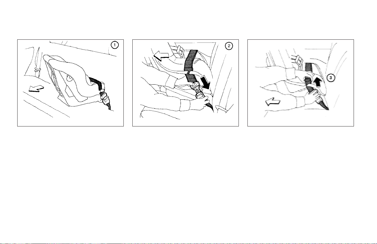
WRS0266
Rear Facing — step 1
Rear facing
When you install a child restraint in the rear
center seat, follow these steps:
1. Position the child restraint on the seat as
illustrated. Always follow the restraint manu-
2. Route the seat belt tongue through the child
Rear Facing — step 2
restraint andinsert it into the buckle until you
hear and feel the latch engage.
Be sure to follow the child restraint manufacturer’s instructions for belt routing.
facturer’s instructions.
1-34 Safety—Seats, seat belts and supplemental air bags
WRS0267
WRS0268
Rear Facing — step 3
3. Remove all slack in the lap belt for a very
tight fit by pulling forcefully on the lap belt
adjustment.
Page 53
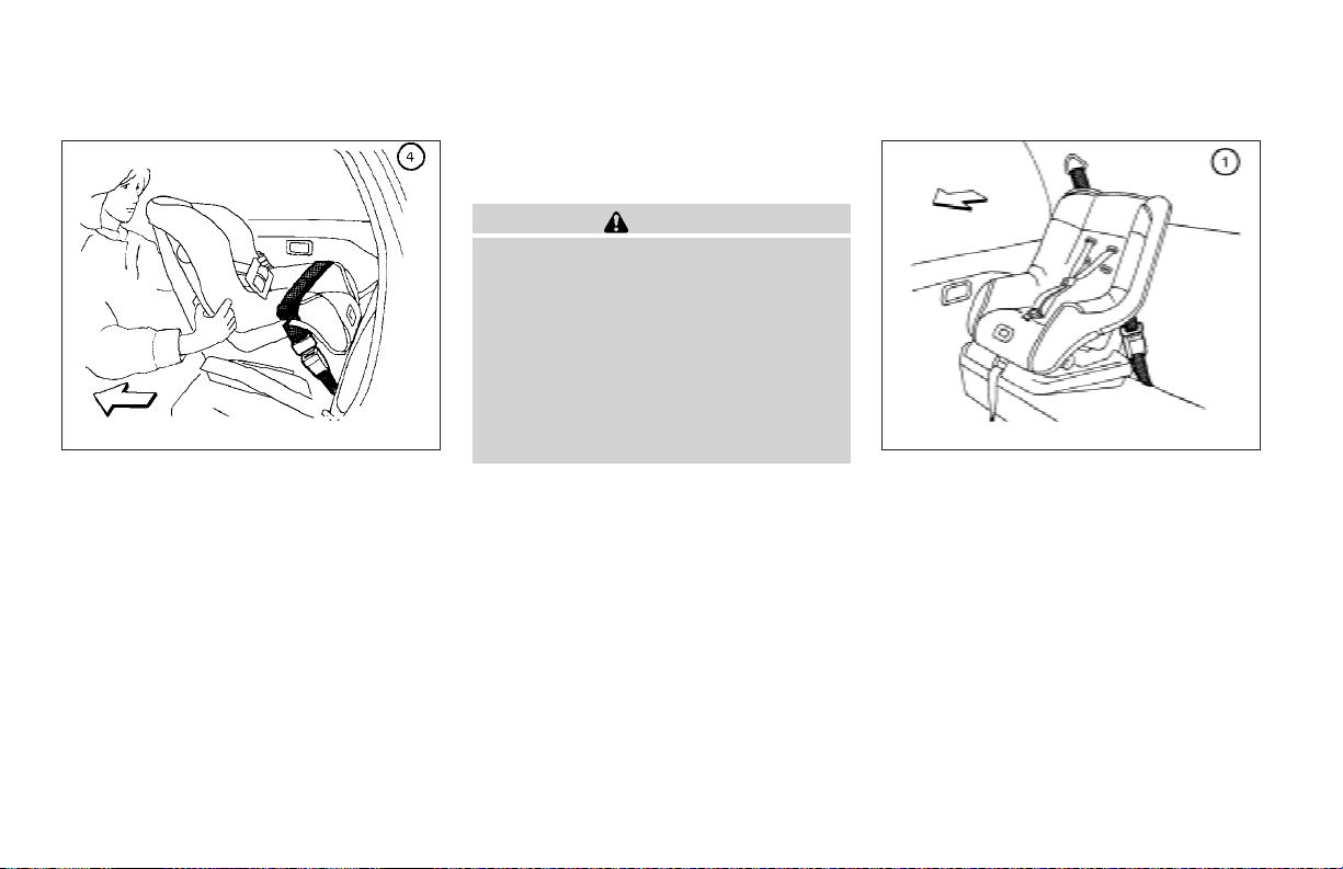
WRS0269
Rear Facing — step 4
4. Before placing the child in the child restraint,
use force to tilt the child restraint from side
to side, and tug it forward to make sure it is
securely in place. It should not move more
than 1 inch (25mm).
5. If it is not secure,try to tighten the belt again,
or put the restraint in another seat.
6. Check to make sure the child restraint is
properly secured prior to each use.
INSTALLATION ON REAR SEAT
OUTBOARD POSITIONS
WARNING
● The three-point seat belt in your vehicle
is equipped with an automatic locking
mode retractor which must be used
when installing a child restraint.
● Failure to use the retractor’s locking
mode will result in the child restraint
not being properly secured. The restraint could tip over or otherwise be
unsecured and cause injury to the child
in a sudden stop or collision.
WRS0272
Front Facing — step 1
Front facing
When you install a child restraint in a rear outboard seat, follow these steps:
1. Position the child restraint on the seat. Always follow the restraint manufacturer’s instructions.
Safety—Seats, seat belts and supplemental air bags 1-35
Page 54
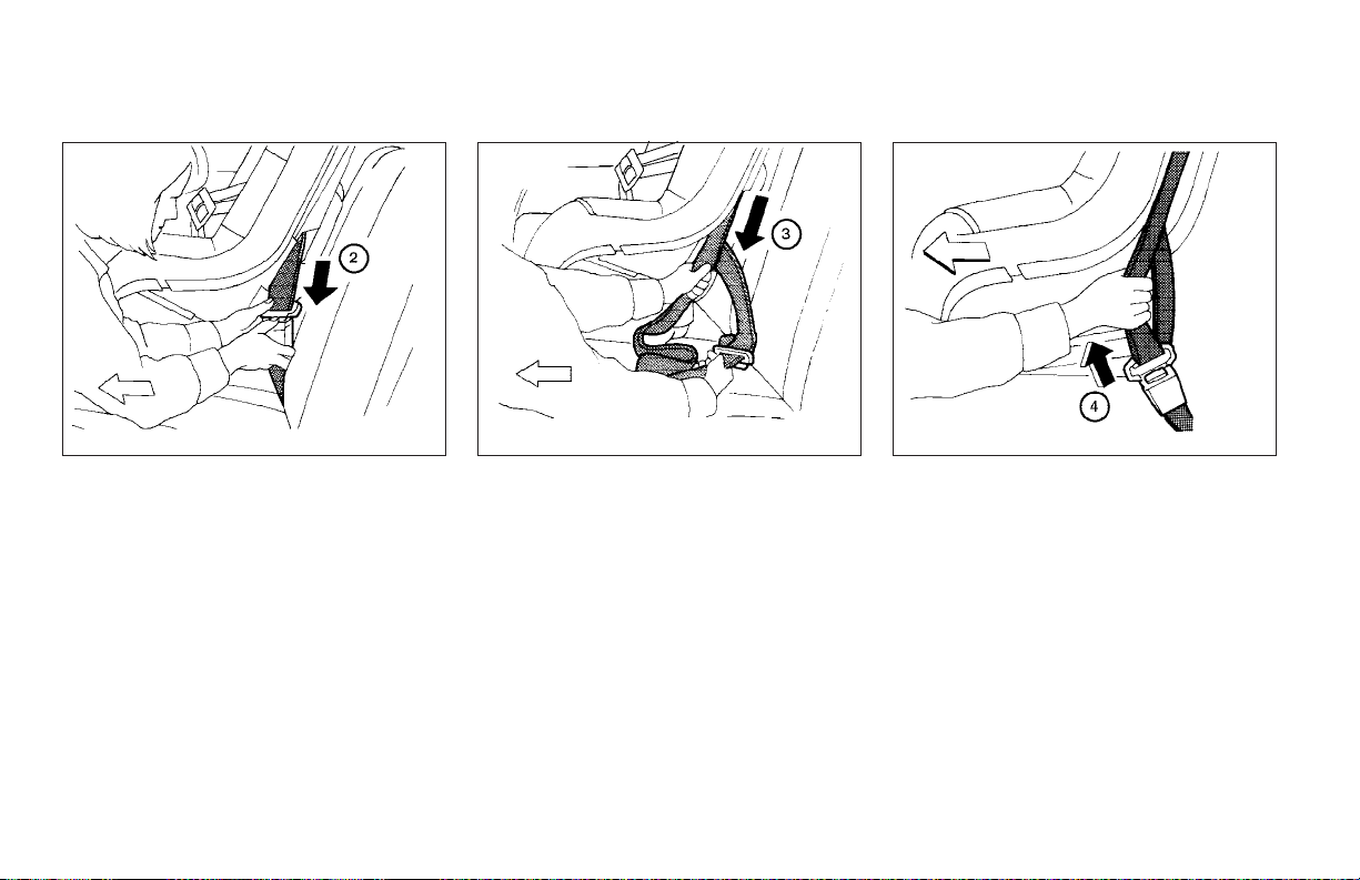
WRS0250
Front Facing — step 2
2. Route the seat belt tongue through the child
restraint andinsert it into the buckle until you
hear and feel the latch engage.
Be sure to follow the child restraint manufacturer’s instructions for belt routing.
3. Pull on the shoulder belt until all of the belt is
Front Facing — step 3
fully extended. At this time, the belt retractor
is in the automatic locking mode (child restraint mode). It reverts back to emergency
locking modewhen thebelt is fully retracted.
1-36 Safety—Seats, seat belts and supplemental air bags
WRS0251
WRS0146
Front Facing — step 4
4. Allow the belt to retract. Pull up on the
shoulder belt to remove any slack in thebelt.
Page 55
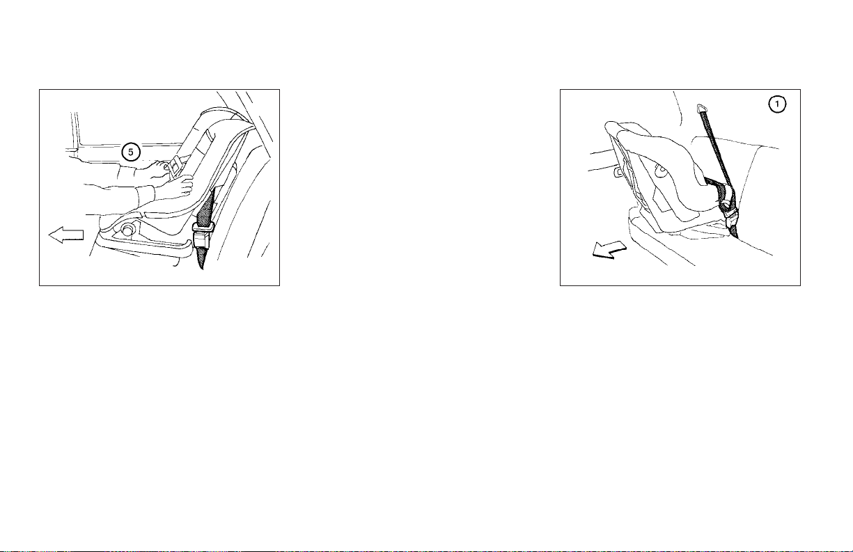
After the child restraint is removed and the seat
belt is fully retracted, the automatic locking mode
(child restraint mode) is canceled.
WRS0252
Front Facing — step 5
5. Before placing the child in the child restraint,
use force to tilt the child restraint from side
to side, and tug it forward to make sure it is
securely held in place. It should not move
more than 1 inch (25mm).
6. Check that the retractor is in the automatic
locking mode by trying to pull more belt out
of the retractor. If you cannot pull any more
belt webbing out of the retractor, the retractor is in the automatic locking mode.
7. Check to make sure the child restraint is
properly secured prior to each use. If the belt
is not locked, repeat steps 3 through 6.
WRS0273
Rear Facing — step 1
Rear facing
When you install a child restraint in a rear outboard seat, follow these steps:
1. Position the child restraint on the seat. Always follow the restraint manufacturer’s instructions.
Safety—Seats, seat belts and supplemental air bags 1-37
Page 56
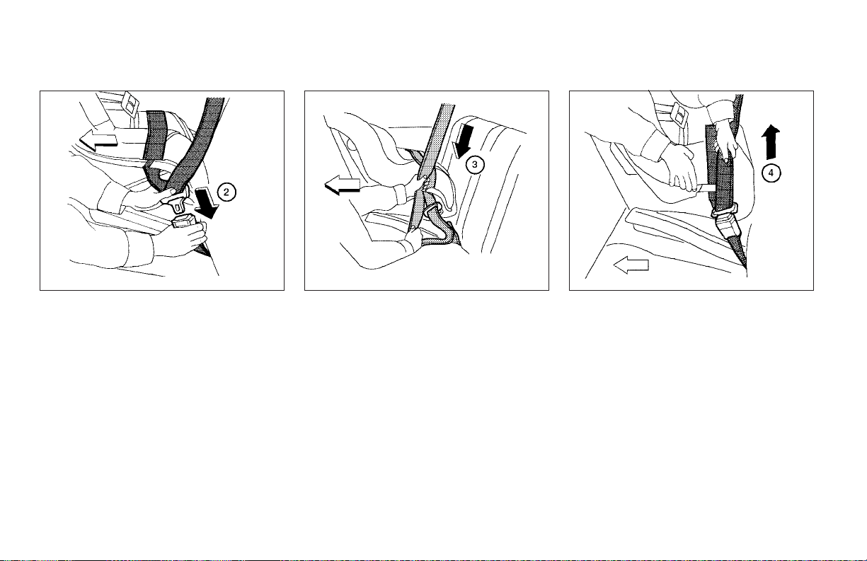
WRS0309
Rear Facing — step 2
2. Route the seat belt tongue through the child
restraint andinsert it into the buckle until you
hear and feel it engage.
Be sure to follow the child restraint manufacturer’s instructions for belt routing.
3. Pull on the shoulder belt until all of the belt is
Rear Facing — step 3
fully extended. At this time, the belt retractor
is in the automatic locking mode (child restraint mode). It reverts back to emergency
locking modewhen thebelt is fully retracted.
1-38 Safety—Seats, seat belts and supplemental air bags
WRS0260
WRS0253
Rear Facing — step 4
4. Allow the belt to retract. Pull up on the
shoulder belt to remove any slack in thebelt.
Page 57
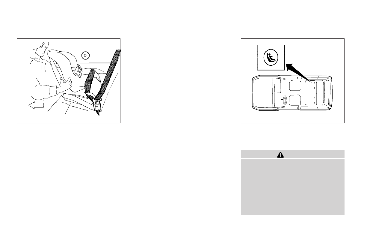
After the child restraint is removed and the seat
belt is fully retracted, the automatic locking mode
(child restraint mode) is canceled.
WRS0254
Rear Facing — step 5
5. Before placing the child in the child restraint,
use force to tilt the child restraint from side
to side, and tug it forward to make sure it is
securely held in place. It should not move
more than 1 inch (25mm).
6. Check that the retractor is in the automatic
locking mode by trying to pull more belt out
of the retractor. If you cannot pull any more
belt webbing out of the retractor, the retractor is in the automatic locking mode.
7. Check to make sure the child restraint is
properly secured prior to each use. If the belt
is not locked, repeat steps 3 through 6.
WRS0438
LATCH system anchor point locations
LATCH (Lower Anchors and Tethers
for CHildren) SYSTEM
WARNING
● Attach LATCH system compatible child
restraints only at the locations shown.If
a child restraint is not secured properly,
your child could be seriously injured or
killed in an accident.
● Do not secure a child restraint in the
center rear seating position using the
LATCH system anchors. The child restraint will not be secured properly.
Safety—Seats, seat belts and supplemental air bags 1-39
Page 58
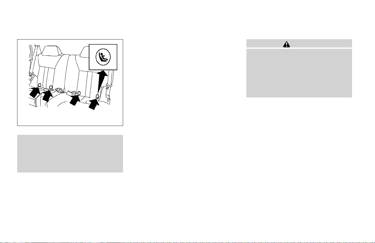
seat belt to secure thechild restraint. Your vehicle
is equipped with special anchor points that are
used with LATCH system compatible child restraints. Check your child restraint for a label
stating that it is compatible with the LATCH system. This information may also be in the child
restraint owner’s manual. If you have such a child
restraint, refer to the illustration for the seating
positions equipped with LATCH system anchors
which can be used to secure the child restraint.
The LATCH system anchors are located at the
rear of the seat cushion near the seatback. A
WRS0206
LATCH anchor point labels
● The LATCH system anchors are designed to withstand only those loads
imposed by correctly fitted child restraints. Under no circumstance are
they to be used for adult seat belts or
harnesses.
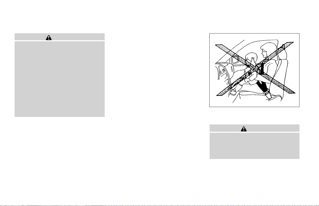
Some child restraints include two rigid or
webbing-mounted attachments that can be connected to two anchors located at certain seating
positions in your vehicle. This system is known as
the LATCH (LowerAnchors andTethersfor CHildren) system. This system may also be referred to
as the ISOFIX or ISOFIX compatible system.
With this system, you do not have to use a vehicle
label is attached to the seatback to help you
locate the LATCH system anchors.
LATCH child restraints generally require the use
of a top tether strap. See “Top tether strap child
restraint” later in this section for installation instructions.
When installing a child restraint, carefully read
and follow the instructions in this manual and
those supplied with the child restraint.
When you install a LATCH system compatible
child restraint to the lower anchor attachments,
follow these steps:
1-40 Safety—Seats, seat belts and supplemental air bags
WARNING
Inspect the lower anchors by inserting
your fingers into the lower anchor area
and feeling to make sure there are no
obstructions over the LATCH system anchors, such as seat belt webbing or seat
cushion material. The child restraint will
not be secured properly if the LATCH system anchors are obstructed.
1. To install the LATCH system compatible
child restraint, insert the child restraint
LATCH system anchor attachments into the
anchor points on the seat. If the child restraint is equipped with a top tether, see
“Top tether strap child restraint” later in this
section for installation instructions.
2. After attaching the child restraint and before
placing the child in it, use force to push the
child restraint from side to side and tug it
forward to make sure that the child restraint
is securely held in place. It should not move
more than 1 inch.
3. Check to make sure thatthe child restraint is
properly secured prior to each use.
Page 59
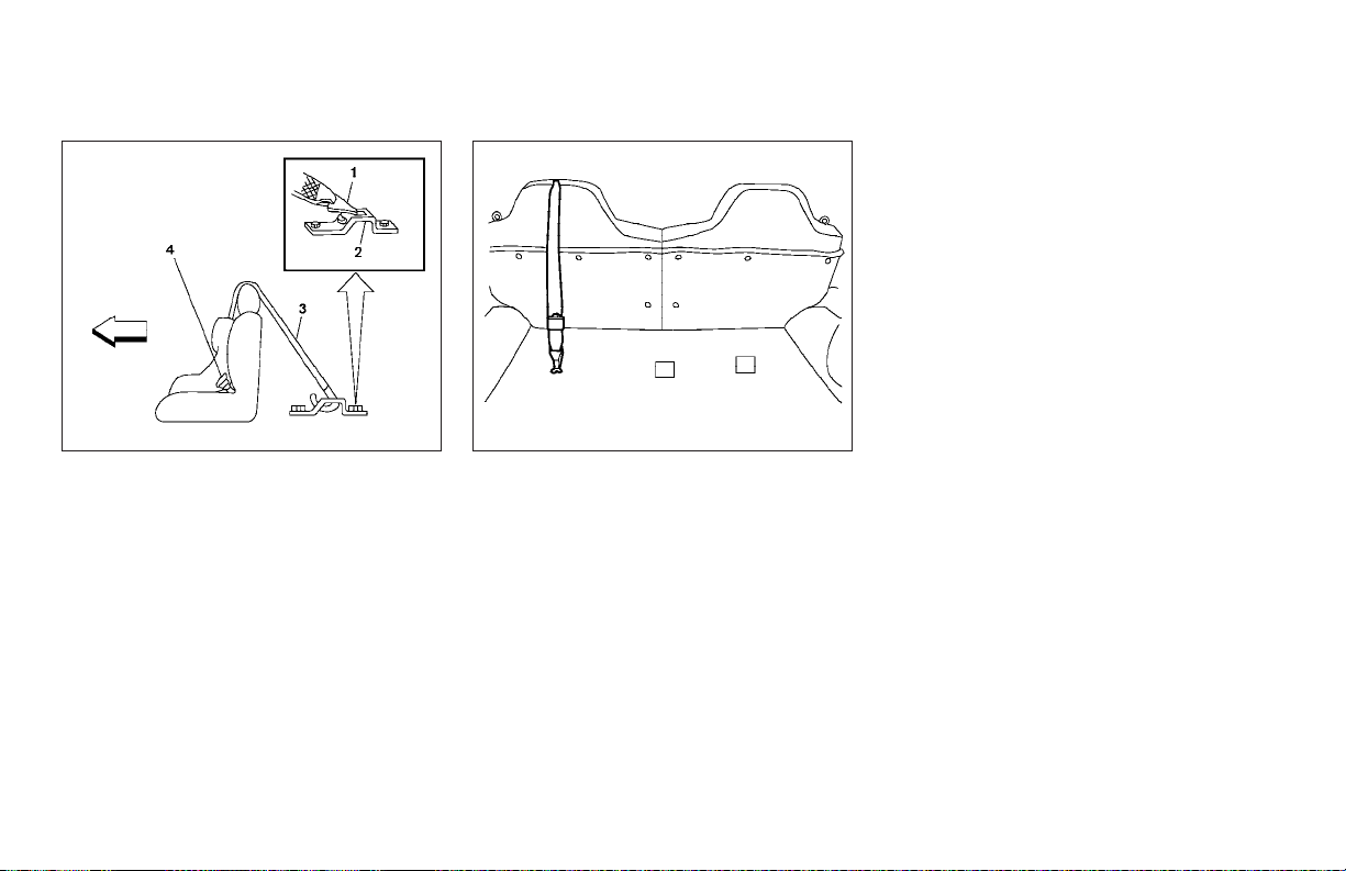
structions to remove any slack. Make sure the
shoulder belt is placed between the seat back
and child restraint.
For therear outboardseating positions, place the
top tether strap over the seat back as shown in
the illustration.
Rear seat outboard position
1. Hook
2. Anchor bracket
3. Tether strap
4. Tongue and buckle fastened
WRS0207
WRS0209
Rear seat outboard position
TOP TETHER STRAP CHILD
RESTRAINT
This vehicle is equipped with 3 anchor brackets
in the rear cargo area for attaching child restraint
top tether straps.
If your child restraint has a top tether strap, secure the child restraint withthe two-point (center)
or three-point seat belt and latch the top strap
hook onto the anchor bracket which provides the
straightest installation of the tether strap. Tighten
the strap according to the manufacturer’s in-
Safety—Seats, seat belts and supplemental air bags 1-41
Page 60
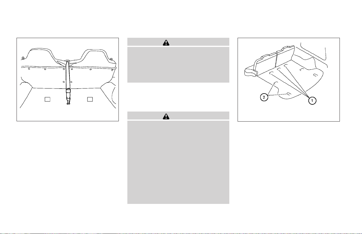
WARNING
In the center position the top tether strap
must be correctly placed between the split
in the rear seat back cushions. If the child
restraint top tether strap is not secured
properly, your child could be seriously injured or killed in an accident.
Secure thetop strapto the attaching bracket that
provides the straightest installation of the strap.
Tighten the strap according to the manufacturer’s instructions to remove any slack.
WRS0208
Rear seat center position
For therear center seating position, place the top
tether strap through the split between the rear
seat back cushion as shown in the illustration.
Position the tether as low as possible in the split
before tightening the top tether strap. Do not
place the top tether strap over the seat back to
the side of the split when installing a child restraint in the center rear position. In that position
the top tether strap may not stay in place and not
keep the child restraint secure in a crash.
● Child restraint anchor points are designed to withstand only those loads
imposed by correctly fitted child restraints. Under no circumstances are
they to be used for adult seat belts or
harnesses.
● The child restraint top tether strap may
be damaged by contact with the tonneau cover or items in the cargo area.
Remove the tonneau cover from the vehicle or secure it and any cargo. Your
child could beseriously injured or killed
in a collision if the top tether strap is
damaged.
1-42 Safety—Seats, seat belts and supplemental air bags
WARNING
WRS0232
1. Anchor point locations
2. Cargo tie down hook flaps
Anchor point locations
Anchor points are located inthe cargoarea under
the carpet
If you have any questions when installing a
top strap child restraint on the rear seat,
consult your NISSAN dealer for details.
s
1
.
Page 61
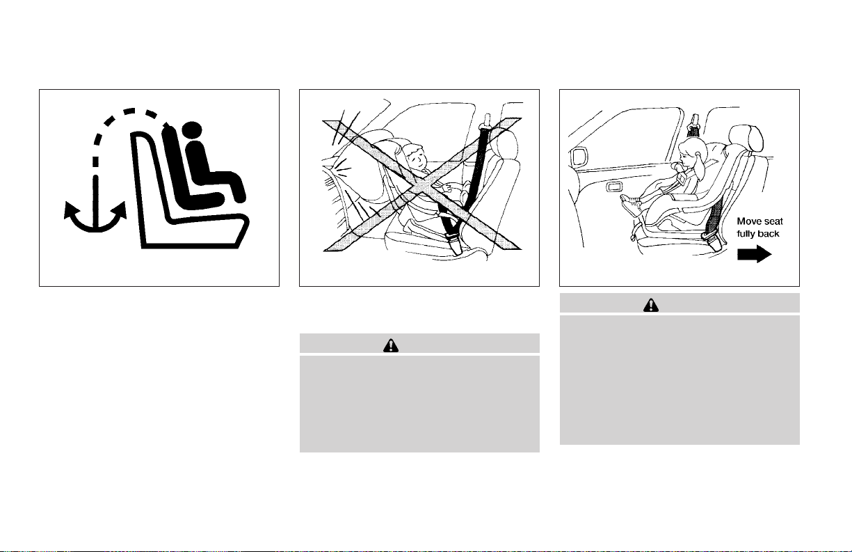
WRS0210 WRS0256 WRS0378
Flaps are provided in the carpet for easy access
to theanchor pointlocations andare markedwith
the label shown.
INSTALLATION ON FRONT
PASSENGER SEAT
WARNING
● Never install a rear-facing child restraint in the front passenger seat.
Supplemental frontair bags inflate with
great force. A rear-facing child restraint
could be struck by the supplemental
front air bag in a crash and could seriously injure or kill your child.
Safety—Seats, seat belts and supplemental air bags 1-43
WARNING
● NISSAN recommends that child restraints be installed in the rear seat.
However, if you must install a forwardfacing child restraint in the front passenger seat, move the passenger seat
to the rearmost position.
● A child restraint with a top tether strap
should not be used in the front passenger seat.
Page 62
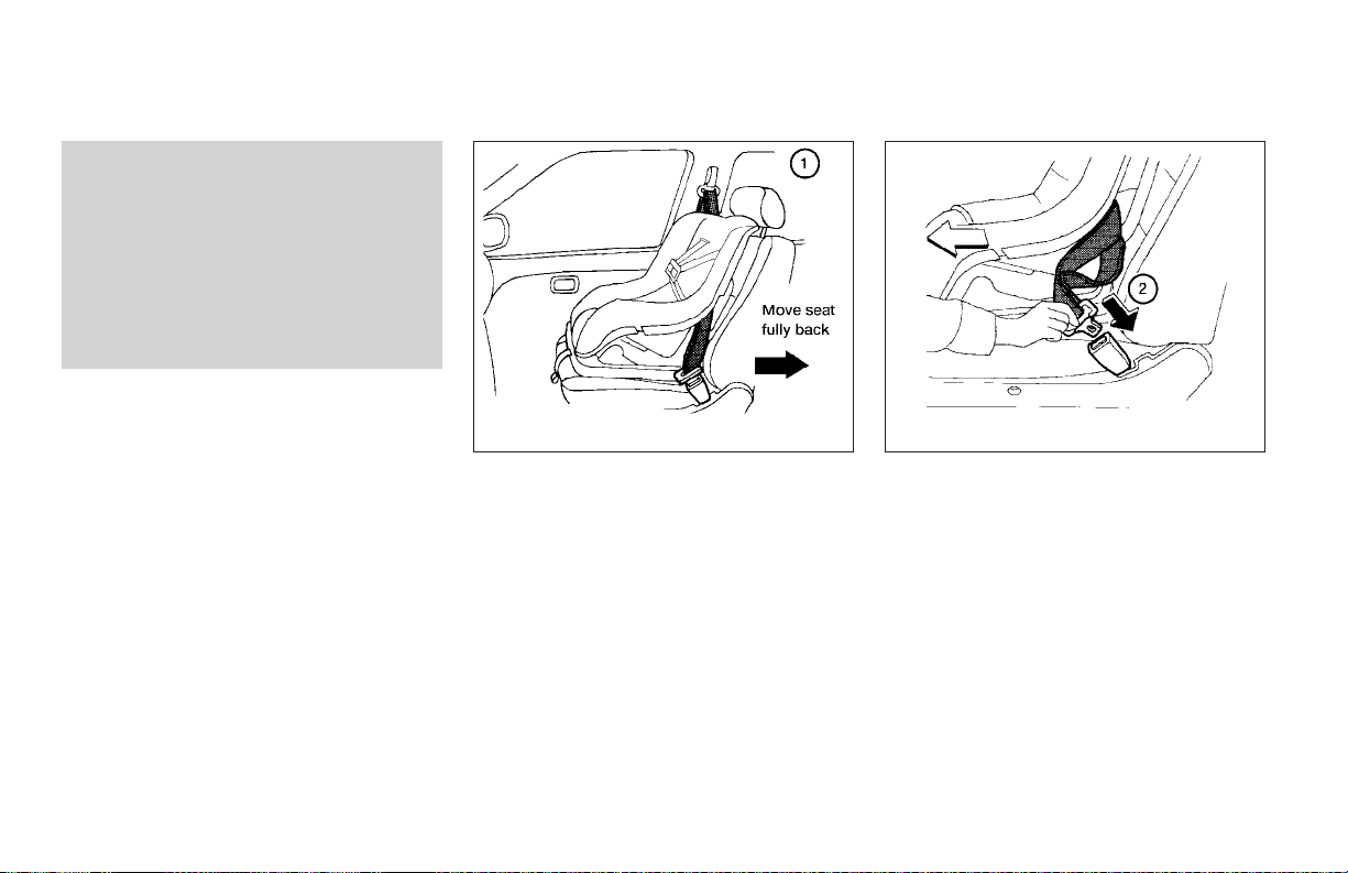
● The three-point seat belt in your vehicle
is equipped with an automatic locking
mode retractor which must be used
when installing a child restraint.
● Failure to use the retractor’s locking
mode will result in the child restraint
not being properly secured. The restraint could tip over or otherwise be
unsecured and cause injury to the child
in a sudden stop or collision.
Front Facing — step 1
If youmust install a child restraint in the front seat,
follow these steps:
1. Position the child restraint on the front passenger seat. It should be placed in a
front-facing direction only. Move the
seat to the rearmost position. Adjust the
head restraint to its highest position. Always
follow the child restraint manufacturer’s instructions. Child restraints for infants
must be used in the rear-facing direction and therefore must not be used in
the front seat.
1-44 Safety—Seats, seat belts and supplemental air bags
WRS0379
WRS0159
Front Facing — step 2
2. Route the seat belt tongue through the child
restraint andinsert it into the buckle until you
hear and feel the latch engage.
Be sure to follow thechild restraintmanufacturer’s instructions for belt routing.
Page 63
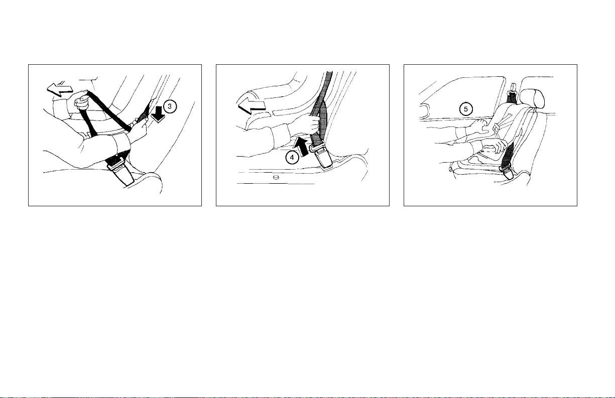
WRS0160
Front Facing — step 3
3. Pull on the shoulder belt until all of the belt is
fully extended. At this time, the seat belt
retractor is in the automatic locking mode
(child restraint mode). It reverts to emergency locking mode when the seat belt is
fully retracted.
WRS0161
Front Facing — step 4
4. Allow the seat belt to retract slightly. Pull up
on the shoulder belt to remove any slack in
the belt.
If necessary to ensure the child restraint is
secure, pull the shoulder belt through the
seat belt tongue beyondthe stitchingin the
belt.
After the seat belt is fully retracted and the child
restraint is removed from the seat, the stitching
on the shoulder belt can be pulled back through
the seat belt tongue. This stitching locates the
seat belt tongue near the top of the seat back for
easy access for passengers.
Safety—Seats, seat belts and supplemental air bags 1-45
WRS0380
Front Facing — step 5
5. Before placing the child in the child restraint,
use force to tilt the child restraint from side
to side, and tug it forward to make sure that
it is securely held inplace. Itshould not move
more than 1 inch.
6. Check that the retractor is in the automatic
locking mode by trying to pull more seat belt
out of the retractor. If you cannot pull any
more belt webbing out of the retractor, the
retractor is in the automatic locking mode.
Page 64

7. Check to make sure the child restraint is
properly secured prior to each use. If the
seat belt is not locked, repeat steps 3
through 6.
After the child restraint is removed and the seat
belt is fully retracted, the automatic locking mode
(child restraint mode) is canceled.
1-46 Safety—Seats, seat belts and supplemental air bags
Page 65

MEMO
Safety—Seats, seat belts and supplemental air bags 1-47
Page 66

2 Instruments and controls
Instrument panel...................................2-2
Meters and gauges ................................2-3
Speedometer and odometer .....................2-3
Tachometer....................................2-5
Engine coolant temperature gauge ...............2-5
Fuel gauge ....................................2-6
Compass and outside temperature display
(if so equipped) ...................................2-6
Outside temperature display .....................2-7
Compass display ...............................2-7
Warning/indicator lights and audible reminders .......2-9
Checking bulbs ................................2-9
Warning lights ................................2-10
Indicator lights ................................2-13
Audible reminders .............................2-15
Security system (if so equipped) ...................2-15
Vehicle security system.........................2-15
Windshield wiper and washer switch ...............2-18
Switch operation ..............................2-18
Rear window wiper and washer switch..............2-19
Rear window defroster switch......................2-20
Headlight and turn signal switch....................2-20
Headlight control switch........................2-20
Daytime running light system (Canada only) ......2-21
Instrument brightness control ...................2-22
Turn signal switch .............................2-22
Fog light switch (if so equipped) ................2-22
Hazard warning flasher switch .....................2-23
Horn ............................................2-23
Vehicle dynamic control (VDC) off switch
(if so equipped) ..................................2-24
Power outlet .....................................2-24
Dual 12 volt power outlets (if so equipped) ..........2-26
Cigarette lighter ..................................2-26
Storage .........................................2-27
Storage compartment..........................2-27
Storage trays (if so equipped)...................2-27
Roof headliner net (if so equipped) ..............2-28
Map pocket...................................2-29
Cup holders ..................................2-29
Glove box ....................................2-30
Console box (if so equipped) ...................2-30
Luggage hooks................................2-31
Tonneau cover (if so equipped)..................2-33
Tubular roof rack with gear basket ...............2-34
Windows ........................................2-37
Page 67

Power windows (if so equipped) ................2-37
Manual windows ..............................2-39
Sunroof (if so equipped)...........................2-40
Manual sunroof................................2-40
Removing/installing ............................2-41
Interior lights .....................................2-41
Map lights (if so equipped) ........................2-42
Page 68
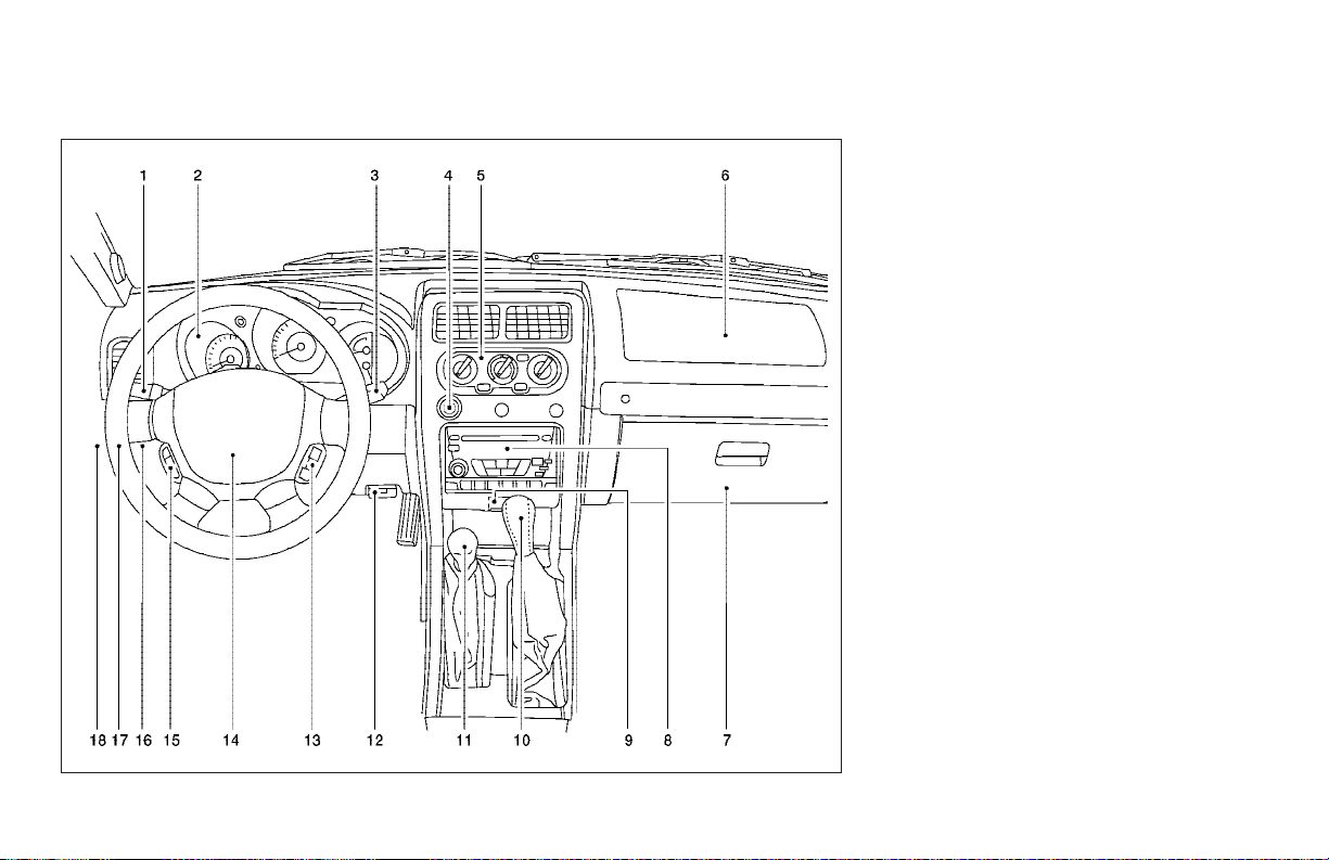
INSTRUMENT PANEL
2-2 Instruments and controls
WIC0641
1. Headlight/fog light (if so equipped)/turn
signal switch (P. 2-20)
2. Meters and gauges (P. 2-3)
3. Windshield wiper/washer switch
(P. 2-18) and rear window wiper/washer
switch (if so equipped) (P. 2-19)
4. Power outlet/cigarette lighter
(P. 2-24, P. 2-26)
5. Heater and air conditioner (P. 4-2)
6. Front passenger supplemental air bag
(P. 1-8)
7. Glove box (P. 2-30)
8. Audio system (P. 4-10)
9. Hazard warning flasher switch (P. 2-23)
10. Automatic/manual selector lever
(P. 5-10)
11. Transfer case shift lever (if so equipped)
(P. 5-19)
12. Parking brake release lever (P. 5-16)
13. Cruise control main/set switch
(if so equipped) (P. 5-16)
14. Driver supplemental air bag/horn
(P. 1-8, P. 2-23)
15. Steering wheel switch for audio controls
(if so equipped) (P. 4-28)
16. Vehicle dynamic control (VDC) off
switch (if so equipped) (P. 2-24)
17. Instrument brightness control (P. 2-22)
18. Rear window wiper and washer switch
(if so equipped)(P. 2-19)
Page 69
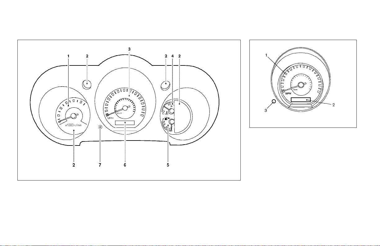
METERS AND GAUGES
1. Tachometer
2. Warning/indicator lights
3. Speedometer
4. Engine coolant temperature gauge
5. Fuel gauge
6. Odometer/twin trip odometer
7. Change button
LIC0631
WIC0632
1. Speedometer
2. Odometer
3. Reset button
SPEEDOMETER AND ODOMETER
Speedometer
The speedometer indicates vehicle speed in
miles per hour (MPH) and kilometers per hour
(km/h).
Odometer/Twin trip
The odometer records the total distance the vehicle has been driven.
Instruments and controls 2-3
Page 70
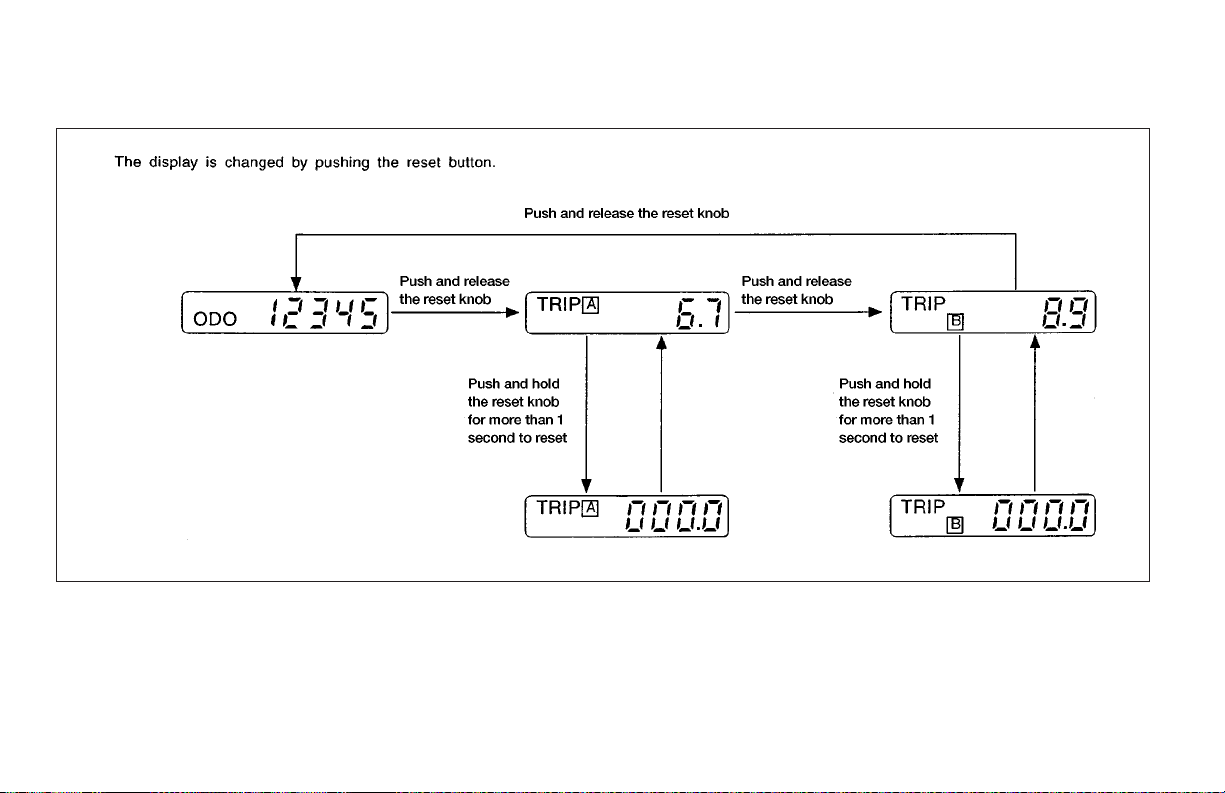
The trip odometer records the distance of individual trips. Before each trip reset the trip odometer.
Push the reset button to change the display as
follows:
2-4 Instruments and controls
AIC1120
ODO (odometer) → TRIP A → TRIP B → ODO
Push and hold the reset button for more than 1
second to reset either trip odometer.
Page 71
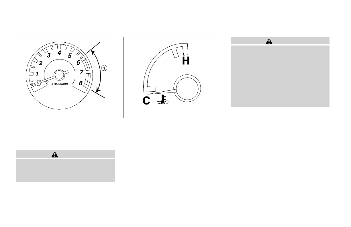
WIC0358 LIC0091
TACHOMETER
The tachometer indicates engine speed in revolutions per minute (rpm). The red zone
shown in the illustration.
CAUTION
When engine speed approaches the red
zone, shift to a higher gear. Operating the
engine in the red zone may cause serious
engine damage.
s
1
ENGINE COOLANT TEMPERATURE
GAUGE
is
The gaugeindicates theengine coolanttemperature. The engine coolant temperature is within the
normal range when the gauge needle points between the C and the H on the gauge.
The engine coolant temperature varies with the
outside air temperature and driving conditions.
CAUTION
If the gauge indicates coolant temperature near the hot (H) end of the normal
range, reduce vehicle speed to decrease
temperature. If the gauge is over the normal range, stop the vehicle as soon as
safely possible. If the engine is overheated, continued operation of the vehicle may seriously damage the engine.
See “If your vehicle overheats” in the “In
case of emergency”section for immediate
action required.
Instruments and controls 2-5
Page 72
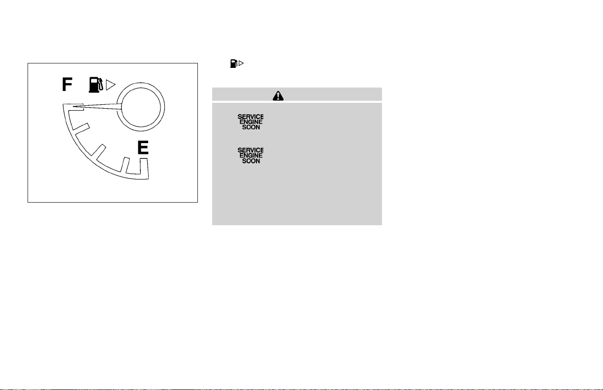
LIC0092
FUEL GAUGE
The gauge indicates the approximate fuel level
in the tank.
The gauge may move slightly during braking,
turning, acceleration, or going up or down hills.
The gauge needle returns to E (Empty) after the
ignition key is turned to OFF.
The low fuel warning light comes on when the
amount of fuel in the tank is getting low.
Refill the fuel tank before the gauge registers E (Empty).
The
cated on the passenger side of the vehicle.
indicates that the fuel filler lid is lo-
CAUTION
● If the vehicle runs out of fuel,
the
(MIL) may come on. Refuel as soon as
possible. After a few driving trips,
the
lamp remains on after a few driving
trips, have the vehicle inspected by a
NISSAN dealer.
● For additional information, see “Malfunction indicator lamp (MIL)” later in
this section.
malfunction indicator lamp
lamp should turn off. If the
COMPASS AND OUTSIDE
TEMPERATURE DISPLAY (if so
equipped)
This unit has the following functions:
● Measures terrestrial magnetism and indicates heading direction of vehicle
● Indicates outside air temperature
2-6 Instruments and controls
Page 73
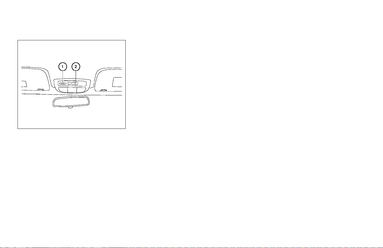
WIC0324
OUTSIDE TEMPERATURE DISPLAY
s
2
1
when the ignition key
s
in °F.
Push the MODE button
is in the ON position. The outside temperature
will be displayed
● Push the MODE button to change from °F to
°C.
● When the outside temperature is between 130°F (55°C) and 158°F (70°C),
the display shows 130°F (55°C) .
● When the outside temperature is lower
than -40°F (-40°C) or higher than 158°F
(70°C), the display shows only———
though it is operating. This is not a
malfunction.
● The outside temperature sensor is located in front of the radiator. The sensor may be affected by road or engine
heat, wind direction and other driving
conditions. The display may differ from
the actual outside temperature or the
temperature displayed on various
signs or billboards.
● Temperature display will not update
unless the vehicle is moving faster
than 12 mph (20 km/h), or the ignition
switch has been OFF for 2 hours.
COMPASS DISPLAY
Push the MODE button
is in the ON position. The direction will be dis-
2
played
s
.
1
when the ignition key
s
Zone variation change procedure
The difference between magnetic north and geographical north is known as variance. In some
areas, this difference can sometimes be great
enough to cause false compass readings. Follow
these instructions to set the variance for your
particular location if this happens:
1. Establish your location on the zone map.
Refer to the illustration. Record your zone
number.
2. Turn the ignition switch to the ON position.
3. Push theMODE buttonin for 5 seconds until
the current zone entry number and the
“VAR” icon is displayed.
4. Press the MODE button repeatedly until the
desired zone entry number is displayed.
Once the desired zone number is displayed, stop
pressing the MODE button and the display will
show compass direction within a few seconds.
NOTE:
Use zone number 5 for Hawaii.
Instruments and controls 2-7
Page 74
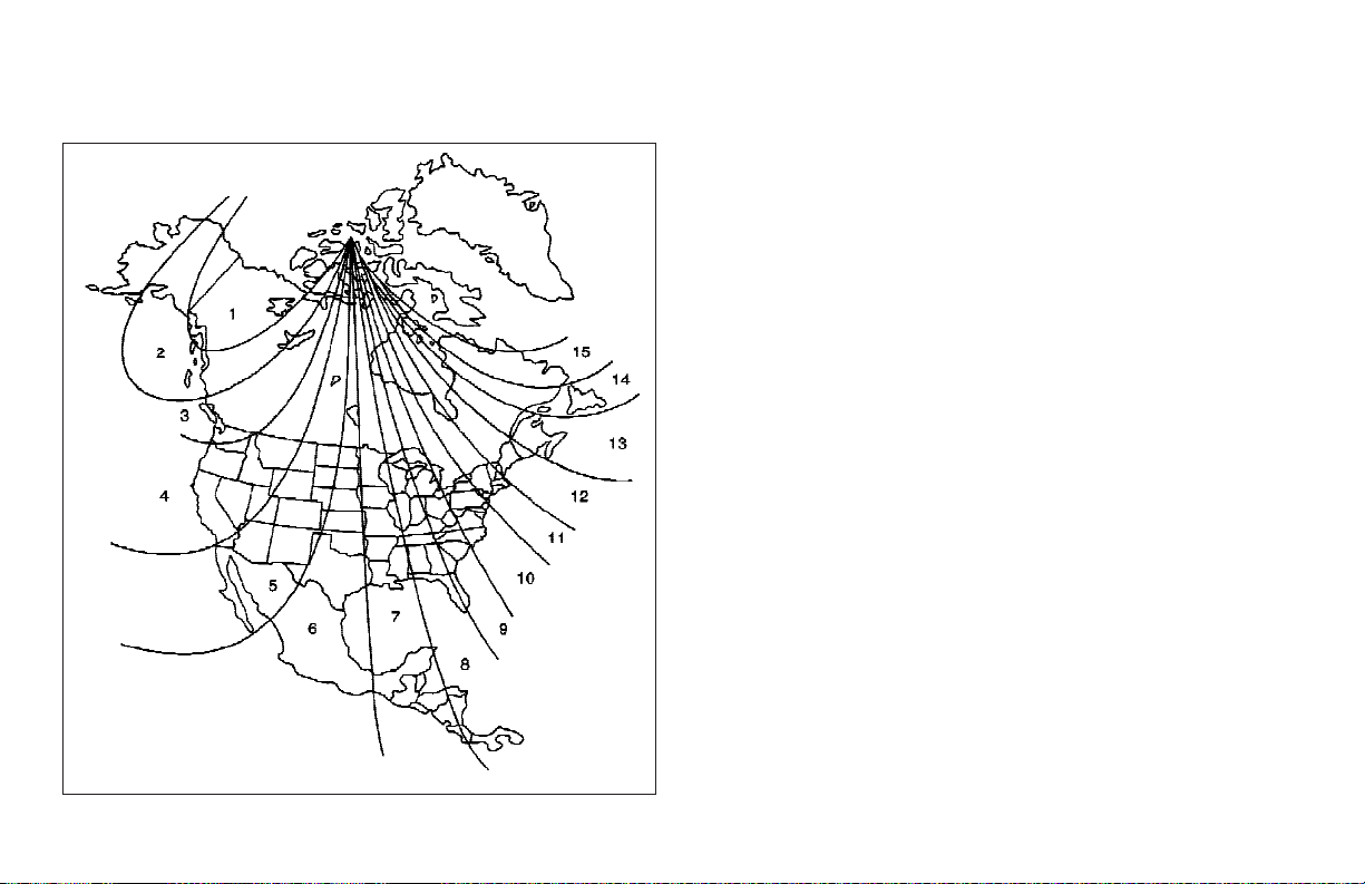
WIC0355
● If a magnet is located near the compass or the vehicle is driven where the
terrestrial magnetism is disturbed, the
compass display may not indicate the
correct direction.
● In places where the terrestrial magnetism is disturbed, the correction of the
direction starts automatically.
Correction functions of the compass
display
The compass display is equipped with automatic
correction function. If the direction is not shown
correctly, carry out the manual correction procedure set out below.
Manual correction procedure
1. Push the MODE button for about 10 seconds. The “CAL” icon will illuminate.
2. Drive the vehicle slowly in an open and safe
area. The initial correction is complete while
turning in 1 or 2 turns.
In places where the earth’s magnetism is disturbed, the initial correction procedure may start
automatically.
2-8 Instruments and controls
Page 75
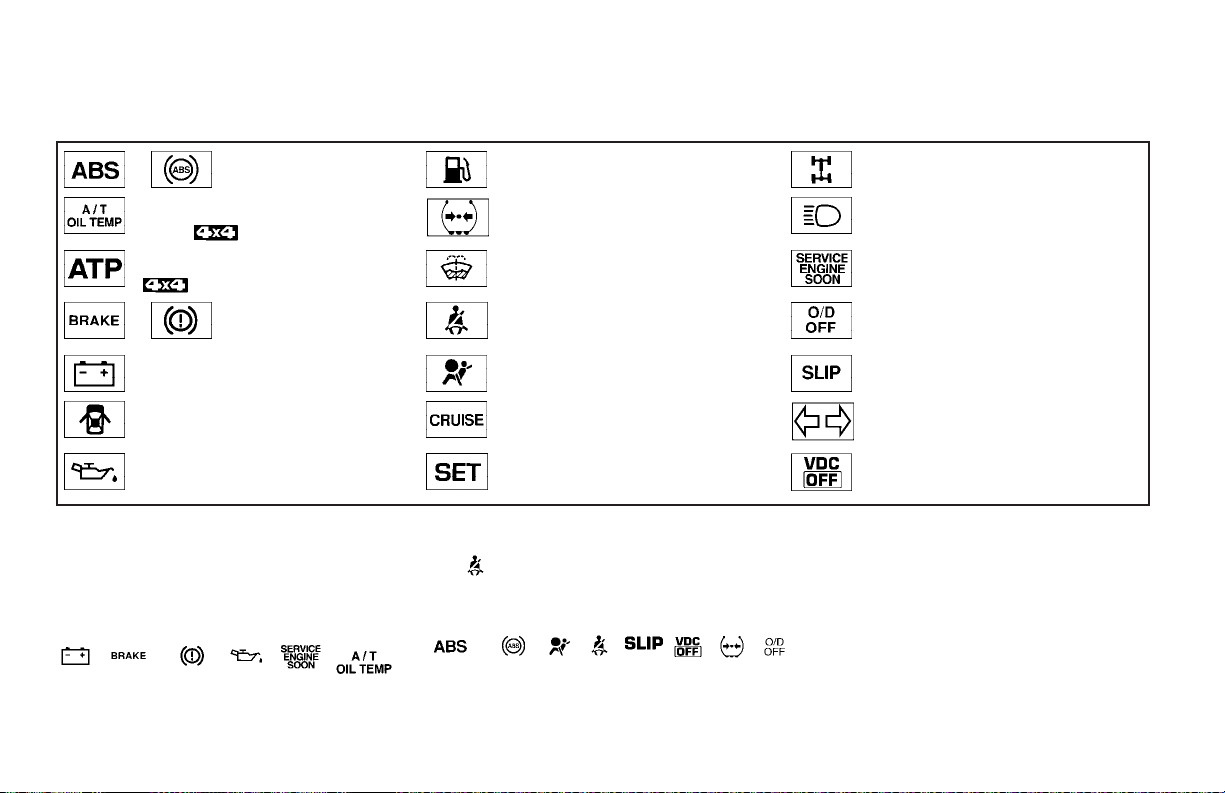
WARNING/INDICATOR LIGHTS AND
AUDIBLE REMINDERS
or Anti-lock brake warning light Low fuel warning light 4-wheel drive indicator light (if so equipped)
Automatic transmission oil temperature warn-
ing light (
Automatic transmission park warning light
(
or Brake warning light Seat belt warning light and chime Overdrive off indicator light (automatic trans-
Charge warning light Supplemental air bag warning light Slip indicator light (if so equipped)
Door open warning light CRUISE main switch indicator light (if so
Engine oil pressure warning light Cruise SET switch indicator light (if so
model)
model)
CHECKING BULBS
With all doors closed, apply the parking brake
and turn the ignition key to the ON position
without starting the engine. The following lights
will come on:
, or , , ,
Low tire pressure warning light (if so equipped) High beam indicator light (Blue)
Low windshield washer fluid warning light (if so
equipped)
equipped)
equipped)
If the driver’s seat belt is fastened before the
ignition key is turned to the ON position,
the
light will not come on.
The following lights come on briefly and then go
off:
or , , , , , ,
Malfunction indicator lamp (MIL)
mission only)
Turn signal/hazard indicator lights
Vehicle dynamic control off indicator light (if so
equipped)
If any light fails to come on, it may indicate
a burned-out bulb or an open circuit in the
electrical system. Have the system repaired
promptly.
Instruments and controls 2-9
Page 76
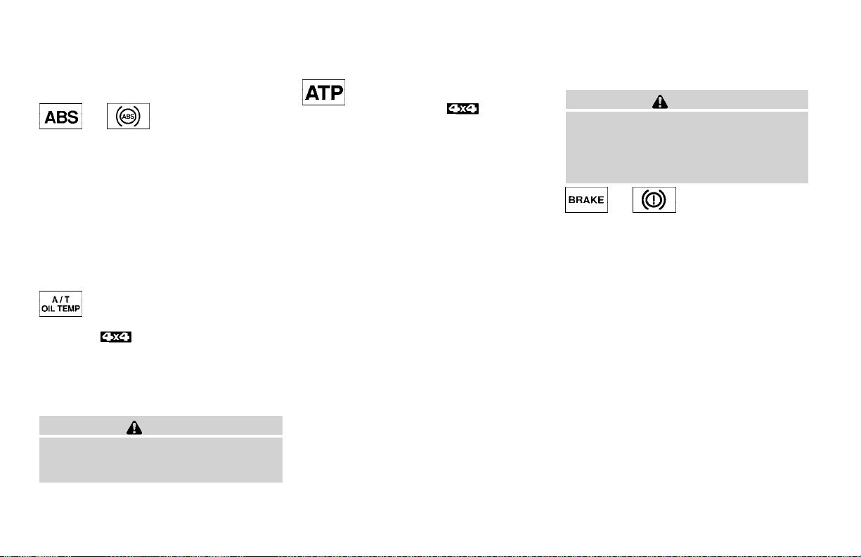
WARNING LIGHTS
or Anti-lock brake
warning light
If the light comes on while the engine is running,
it may indicate the anti-lock brake system is not
functioning properly. Have the system checked
by a NISSAN dealer.
If an abnormality occurs in the system, the antilock function ceases, but the regular braking
system continues to operate.
If the light comes on while you are driving,
contact a NISSAN dealer for repair.
Automatic transmission oil
temperature warning light
(
This light comeson whenthe automatic transmission oil temperature is too high. If the light comes
on while driving, reduce the vehicle speed as
soon as safely possible until the light turns off.
Continued vehicle operation when the A/T
oil temperature warning light is on may
damage the automatic transmission.
model)
CAUTION
Automatic transmission park
warning light (
This light indicates that the automatic transmission parking function is not engaged. If the transfer control shift lever is not secured in any drive
position while the automatic transmission selector lever is in the P (Park) position, the vehicle
may move unexpectedly.
Shift the transfer control shift lever into the 2H,
4H, or 4L position when the warning light comes
on.
● When parking, always make sure that the
transfer control shift lever is in 2H, 4H, or 4L
and the parking brake is set.
● If the ATP light is ON, this indicates that the
automatic transmission P (Park) position will
not function and the transfer control shift
lever is in the N (Neutral) position.
● Failure to engage the transfer shift control
lever in 2H, 4H or 4L could result in the
vehicle moving unexpectedly, resulting inserious personal injury or property damage.
model)
CAUTION
If the ATP light is ON, this indicates that
the automatic transmission P (Park) position will not function and the transfer control shift lever is in the N (Neutral)
position.
or Brake warning light
This lightfunctions for both the parking brake and
the foot brake systems.
When the ignition key is in the ON position, the
light comeson whenthe parkingbrake isapplied,
and also warns of a low brake fluid level. If the
light comes on while the engine is running with
the parking brake not applied, stop the vehicle
and perform the following:
1. Check the brake fluid level. Add brake fluid
as necessary. See “Brake andclutch fluid”in
the “Maintenance and do-it-yourself” section of this manual.
2. If the brake fluid level is correct, have the
brake system checked by a NISSAN dealer.
2-10 Instruments and controls
Page 77
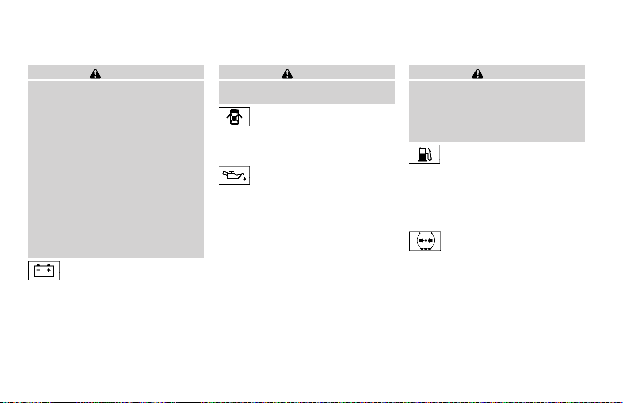
WARNING
● Your brake system may not be working
properly if the warning light is on. Driving could be dangerous. If you judge it
to be safe, drive carefully to the nearest
service station for repairs. Otherwise,
have your vehicle towed because driving it could be dangerous.
● Pressing the brake pedal with the engine stopped and/or a low brake fluid
level may increase your stopping distance and braking will require greater
pedal effort as well as pedal travel.
● If the brake fluid level is below the
MINIMUM or MIN mark on the brake
fluid reservoir, do not drive until the
brake system has been checked at a
NISSAN dealer.
Charge warning light
If this light comes on while the engine is running,
it may indicate the charging system is not functioning properly. Turn the engine off and check
the generator belt. If the belt is loose, broken,
missing, or if the light remains on, see a NISSAN
dealer immediately.
CAUTION
Do not continue driving if the generator
belt is loose, broken or missing.
Door open warning light
This lightcomes on when any of the doors are not
closed securelywhile theignition keyis inthe ON
position.
Engine oil pressure warning
light
This light warns of low engine oil pressure. If the
light flickers or comes on during normal driving,
pull off the road in a safe area, stop the engine
immediately and call a NISSAN dealer or other
authorized repair shop.
The engine oil pressure warning light is not
designed to indicate a low oil level. Use the
dipstick to check the oil level. See “Engine oil” in
the “Maintenance and do-it-yourself” section of
this manual.
CAUTION
Running the engine with the engine oil
pressure warning light on could cause serious damage to the engine almost immediately. Such damage is not covered by
warranty. Turn off the engine as soon as it
is safe to do so.
Low fuel warning light
This light comes on when the fuel level in the fuel
tank is getting low. Refuel as soon as it is convenient, preferably before the fuel gauge reaches E
(Empty). There willbe a small reserve of fuel
in the tank when the fuel gauge needle
reaches E (Empty).
Low tire pressure warning
light (if so equipped)
After the ignition switch is turned ON, this light
comes on for about 1 second and turns off.
This light warns of low tire pressure.
NISSAN’s low tire pressure warning system is a
tire pressure monitoring system. It monitors tire
pressure of all tires except the spare. When the
tire pressure monitoring system warning light is
lit, one or more of your tires is significantly underinflated. You should stop and check your tires as
soon as possible, and inflate them to the proper
Instruments and controls 2-11
Page 78
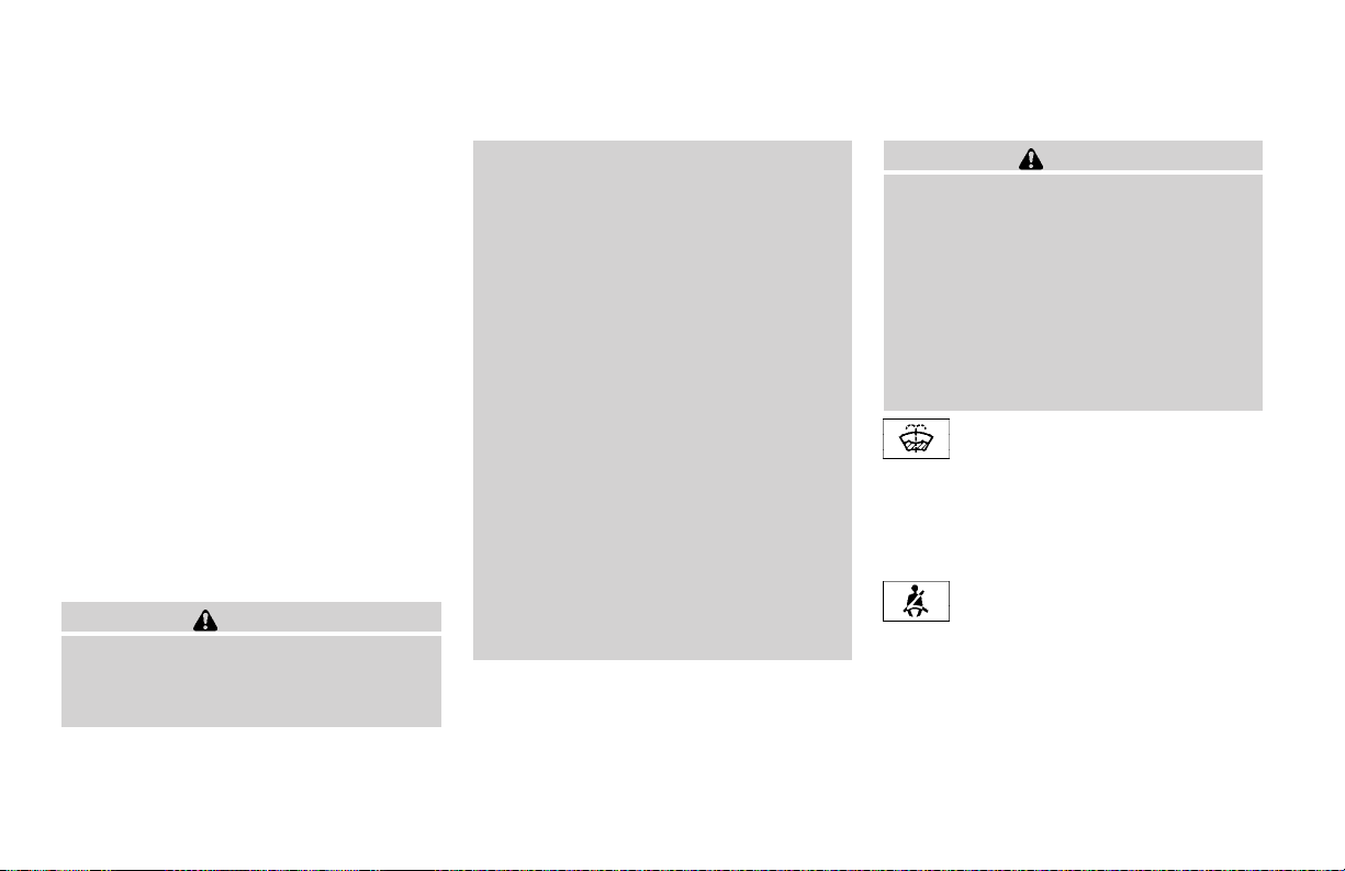
pressure as indicated on the vehicle’s tire information placard. Driving on a significantly underinflated tire causes the tire to overheat and can
lead to tire failure. Under-inflation also reduces
fuel efficiency and tire tread life, and may affect
the vehicle’s handling and stopping ability. Each
tire, including the spare, should be checked
monthly when cold and set to the recommended
inflation pressureas specified in the vehicle placard and owner’s manual.
Low pressure warning
If the vehicle is being driven with very low tire
pressure (lower than 28 psi, 193 kPa), the light
will illuminate and the chime will sound for about
10 seconds.
For additionalinformation, see “Low tire pressure
warning system” in the “Starting and driving”
section and “Low tire pressure warning system”
in the “In case of emergency” section.
WARNING
● If the light does not come on with the
key switch turned ON, have the vehicle
checked by a NISSAN dealer as soon as
possible.
2-12 Instruments and controls
● If the light comes on while driving,
avoid sudden steering maneuvers or
abrupt braking, reduce vehicle speed,
pull off the road to a safe location and
stop the vehicle as soon as possible.
Serious vehicle damage could occur
and may lead to an accident and could
result in serious personal injury. Check
the tirepressure for all four tires. Adjust
the tire pressure to the recommended
COLD tire pressure shown on the tire
placard to turn the low tire pressure
warning light OFF. If the light still
comes on while driving after adjusting
the tire pressure, a tire may be flat. If
you have a flat tire, replace it with a
spare tire as soon as possible.
● When a spare tireis mountedor awheel
is replaced, tire pressure will not be
indicated and the low tire pressure
warning system will not function. Contact your NISSAN dealer as soon as
possible for tire replacement and/or
system resetting.
CAUTION
● The low tire pressure warning system is
not a substitute for the regulartire pressure check. Be sure to check the tire
pressure regularly.
● If the vehicle is being driven at speeds
of less than 20 MPH (32 km/h), the low
tire pressure warning system may not
operate correctly.
● Be sure to install the specified size of
tires to the 4 wheels correctly.
Low windshield washer fluid
warning light (if so equipped)
This light comes on when the windshield washer
fluid is at a low level. Add windshield washer fluid as
necessary. See “Window washer fluid” in the “Maintenance and do-it-yourself” section of this manual.
Seat belt warning light and
chime
The light and chime remind you to fasten your
seat belts. The light illuminates whenever the
ignition key is turned tothe ON or STARTposition
and remainsilluminated until the driver’s seatbelt
is fastened. At the same time, the chime sounds
for about 6 seconds unless the driver’s seat belt
is securely fastened.
Page 79
Refer to “Seat belts” in the “Safety—Seats, seat
belts and supplemental air bags” section for precautions on seat belt usage.
Supplemental air bag warning
light
When the ignition key is in the ON or START
position, the supplemental air bag warning light
illuminates for about 7 seconds and then turns
off. This means the system is operational.
If any of the following conditions occur, the
supplemental front air bag, supplemental curtain
side-impact and pre-tensioner seat belt systems
need servicing and your vehicle must be taken to
a NISSAN dealer:
● The supplemental air bag warning light remains on after approximately 7 seconds.
● The supplemental air bag warning light
flashes intermittently.
● The supplemental air bag warning light does
not come on at all.
Unless checked and repaired, the supplemental
restraint system (air bag system) and/or the pretensioner seat belts may not function properly.
For additional details see “Supplemental restraint
system” in the “Safety—Seats, seat belts and
supplemental air bags” section of this manual.
WARNING
If the supplemental air bag warning light
is on, it could mean that the supplemental
front air bag, supplemental curtain sideimpact air bag systems (if so equipped)
and/or pre-tensioner seat belt systems
will not operate in an accident. To help
avoid injury to yourself or others, have
your vehicle checked by a NISSAN dealer
as soon as possible.
INDICATOR LIGHTS
Cruise main switch indicator
light (if so equipped)
The light comes on when the cruise control main
switch is pushed. The light goes out when the
main switch is pushed again. When the cruise
main switch indicator light comes on, the cruise
control system is operational.
Cruise set switch indicator
light (if so equipped)
The light comes on while the vehicle speed is
controlled by the cruise control system. Ifthe light
blinks while the engine is running, it may indicate
the cruise control system isnot functioning properly. Have the system checked by a NISSAN
dealer.
4–wheel drive indicator light
(if so equipped)
This light comes on when the transfer shift control lever is in the 4H or 4L position.
WARNING
● When parking always make sure the
transfer control lever is in the 2H, 4H or
4L position and the parking brake is
applied.
● Failure to engage the transfer control
lever in 2H, 4H or 4L could result in the
vehicle moving unexpectedly, which
could cause serious personal injury or
property damage.
High beam indicator light
(Blue)
This blue light comes on when the headlight high
beams are on and goes out when the low beams
are selected.
The high beam indicator light also comes on
when the passing signal is activated.
Instruments and controls 2-13
Page 80
Malfunction indicator lamp
(MIL)
If this indicator lamp comes on steady or blinks
while the engine is running, it may indicate a
potential emission control malfunction.
The malfunctionindicator lampmay alsocome on
steady if the fuel filler cap is loose or missing,or if
the vehicle runs out of fuel. Check to make sure
the fuel filler cap is installed and closed tightly,
and that the vehicle has at least 3 gallons (11.4
liters) of fuel in the fuel tank.
After a few driving trips, the
turn off if no other potential emission control
system malfunction exists.
Operation
The malfunction indicator lamp will come on in
one of two ways:
● Malfunction indicator lamp on steady — An
emission control system malfunction has
been detected. Check the fuel filler cap. If
the fuel filler cap is loose or missing, tighten
or install the cap and continue to drive the
vehicle. The
a few driving trips. If the
not turn off after a few driving trips, have the
vehicle inspected by a NISSAN dealer. You
lamp should turn off after
lamp should
lamp does
2-14 Instruments and controls
do not need to have your vehicle towed to
the dealer.
● Malfunction indicator lamp blinking — An
engine misfirehas beendetected whichmay
damage the emission control system. To reduce or avoid emission control system damage:
– do not drive at speeds above 45 MPH
(72 km/h).
– avoid hard acceleration or deceleration.
– avoid steep uphill grades.
– if possible, reduce the amount of cargo
being hauled or towed.
The malfunction indicator lamp may stop blinking
and come on steady. Have the vehicle inspected
by a NISSAN dealer. You do not need to have
your vehicle towed to the dealer.
CAUTION
Continued vehicle operation without having the emission control system checked
and repaired as necessary could lead to
poor driveability, reduced fuel economy,
and possible damage to the emission control system.
Overdrive off indicator light
(automatic transmission models only)
This light comes on when the overdrive function
is OFF.
The automatic transmission overdrive function is
controlled by the overdrive switch.
See “Driving the vehicle” in the “Starting and
driving” section of this manual.
Slip indicator light (if so
equipped)
This indicator light will blink when the traction
control system is limiting wheel spin. Slippery
road conditions may exist if the slip indicator
blinks on. If this happens, adjust your driving
accordingly.
The slip indicator light also comes on when you
turn the ignition key to the ON position. The light
will turn off after about 2 seconds if the system is
operational. If the light does not come on or does
not go off, have the traction control system
checked by a NISSAN dealer.
Turn signal/hazard indicator
lights
The appropriatelight flashes when the turn signal
switch is activated.
Page 81
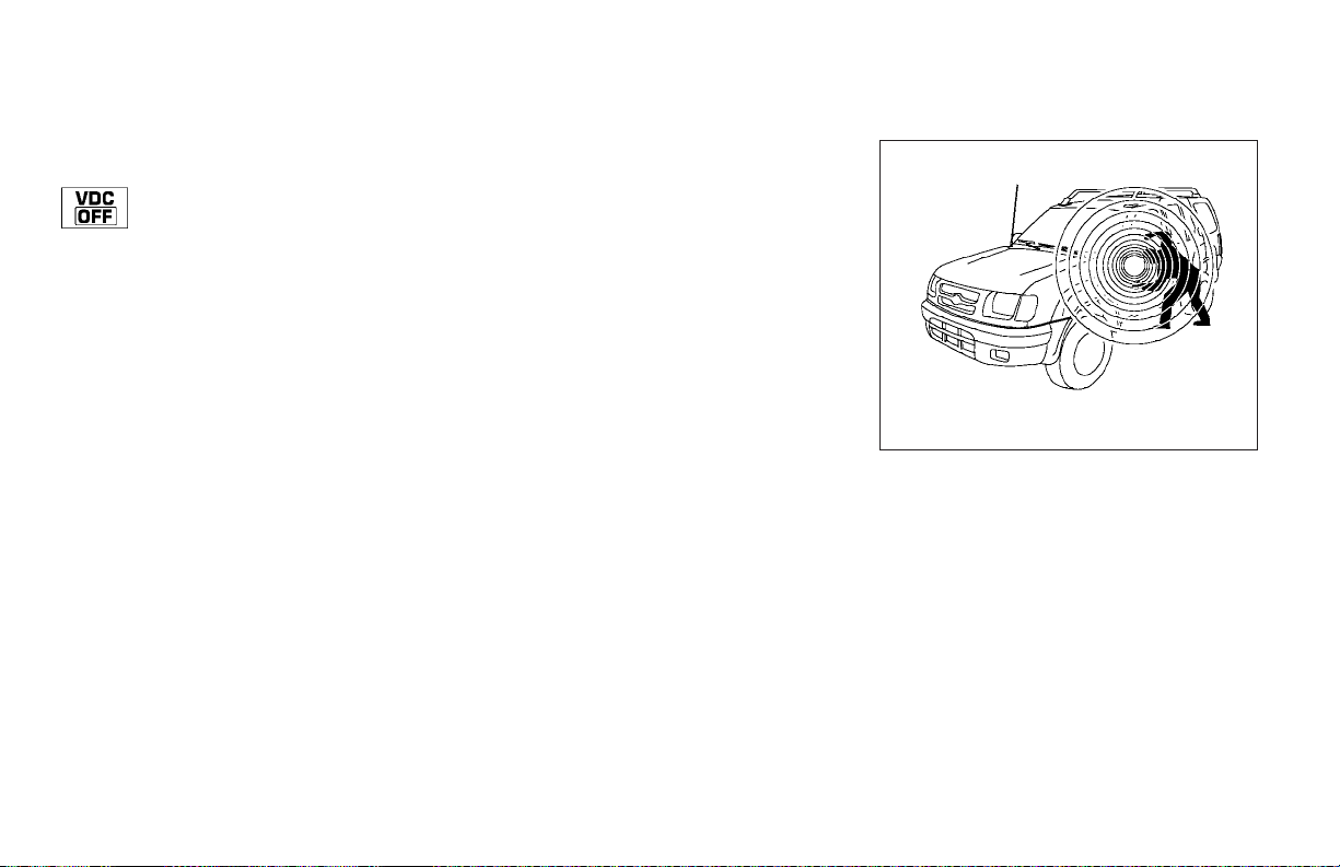
SECURITY SYSTEM (if so equipped)
Both lights flash when the hazard switchis turned
on.
Vehicle dynamic control off
indicator light (if so equipped)
This indicator light comes on when the vehicle
dynamic controloff switchis pushed to OFF. This
indicates the vehicle dynamic control system is
not operating.
Push thevehicle dynamiccontrol off switch again
or restart the engine and the system will operate
normally. See “Vehicle dynamic control (VDC)
system” in the “Starting and driving” section of
this manual.
The vehicle dynamic control light also comes on
when youturn the ignition key tothe ON position.
The light will turn off after about 2 seconds if the
system is operational. If the light stays on or
comes on along with the SLIP indicator light
while you are driving, have the vehicle dynamic
control system checked by a NISSAN dealer.
While the vehicle dynamic control system is operating, you might feel slight vibration or hear the
system working when starting the vehicle or accelerating, but this is normal.
AUDIBLE REMINDERS
Brake pad wear warning
The discbrake padshave audible wear warnings.
When a brake pad requires replacement, it
makes a high pitched scraping sound when the
vehicle is in motion, whether or not the brake
pedal is depressed. Have the brakes checked as
soon as possible if the warning sound is heard.
Key reminder chime
A chime sounds if the driver’s door is opened
while the key is leftin the ignition switch. Remove
the key and take it with you when leaving the
vehicle.
Light reminder chime
With the ignition switch in the OFF position, a
chime sounds when the driver’sdoor is opened if
the headlights or parking lights are on.
Turn the headlight control switch off before leaving the vehicle.
LIC0372
VEHICLE SECURITY SYSTEM
The vehicle security system provides visual and
audio alarm signals if parts of the vehicle are
disturbed.
Instruments and controls 2-15
Page 82
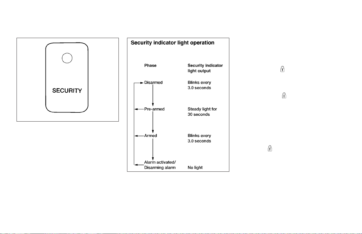
LIC0093
Security indicator light
The security indicator light shows the status of
the vehicle security system.
The lightoperates wheneverthe ignitionswitch is
in the LOCK, OFF, or ACC position.
The vehicle security system has four phases. For
each phase the operation of the securityindicator
light is different.
2-16 Instruments and controls
LIC0053
How to arm the vehicle security system
1. Close all windows. (The system can be
armed even if the windows are open.)
2. Remove the key from the ignition switch.
3. Close the hood and alldoors. Lockall doors.
The doorscan belocked with the key,power
door lock switch or with the keyfob.
Keyfob operation:
● Push the
All doors lock. The hazard lights flash
twice and the horn beepsonce to indicate
all doors are locked.
● When the
all doors locked, the hazard lights flash
twice and the horn beeps once as a reminder that the doors are already locked.
The horn may or may not beeponce. Referto
“Silencing thehorn beepfeature”later in this
section.
● If a door is open and you push
the
horn does not chirp and the hazard lights
do not flash.
button on the keyfob.
button is pushed with
button thedoors lock but the
Page 83
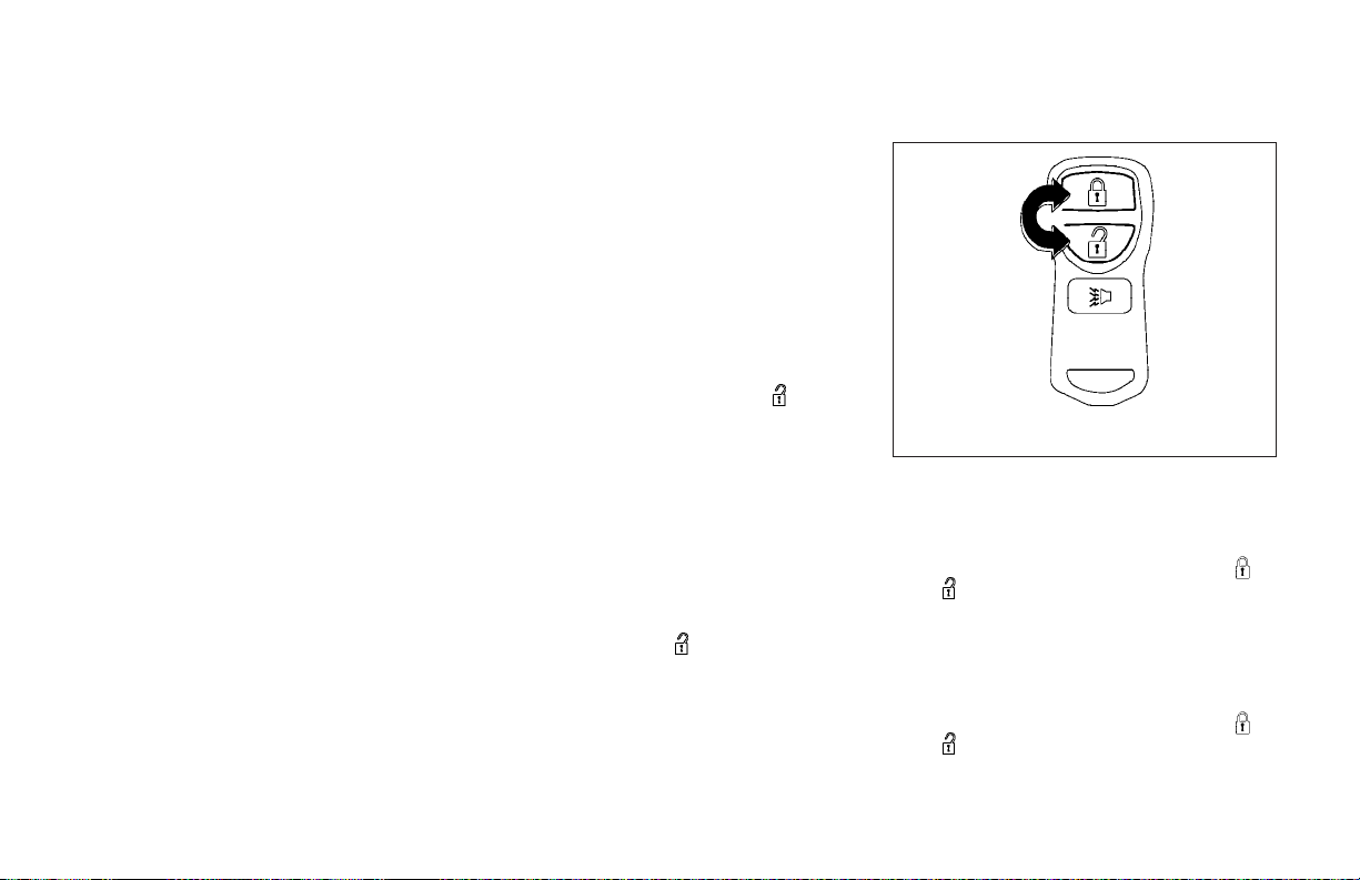
4. Confirm that the SECURITY indicator light
comes on. The SECURITY light stays on for
about 30 seconds. The vehicle security system is now pre-armed. After about 30 seconds the vehicle security system automatically shifts into the armed phase. The
SECURITY light begins to flashonce every 3
seconds. If, during the 30-second pre-arm
time period, the door is unlocked by the key
or the keyfob, or the ignition key is turned to
ACC or ON, the system will not arm.
● If the key is turned slowly when locking
the door, the system may not arm. Furthermore, if the key is turned excessively to the unlock position, the system may be disarmed when the key is
removed. If the indicator light fails to
glow for 30 seconds, unlock the door
once and lock it again.
● Even when the driver and/or passengers are in the vehicle, the system will
arm with all doors and the hood closed
and locked and the ignition key in the
OFF position. Turn the ignition key to
the ACC or ON to turn the security
system off.
Vehicle security system activation
The vehiclesecurity systemwill give the following
alarm:
● The headlights blink and the horn sounds
intermittently. In addition, the starter motor
does not operate.
● The alarm automatically turns off after about
50 seconds. However, the alarm reactivates
if the vehicle is tampered with again. The
alarm can be shut off by unlocking a door
with thekey, or by pressing the
on the keyfob.
The alarm is activated by:
● opening a door without using the key or
keyfob (even if the door is unlocked by releasing the inside lock knob).
● opening the hood.
button
How to stop an activated alarm
The alarmstops only by unlocking a door with the
key or by pressing the
fob.
The alarm does not stop if the ignition
switch is turned to ACC or ON.
button on the key-
WIC0325
Silencing the horn beep feature
If desired, the horn beep feature can be deactivated using the keyfob.
Todeactivate: Pressand holdboth the
and buttons at the same time for at least
2 seconds.
The hazard lights will quickly flash 3 times to
confirm that the horn beep feature has been
deactivated.
To activate: Press and hold both the
and buttons at the same time for at least
2 seconds once more.
Instruments and controls 2-17
Page 84
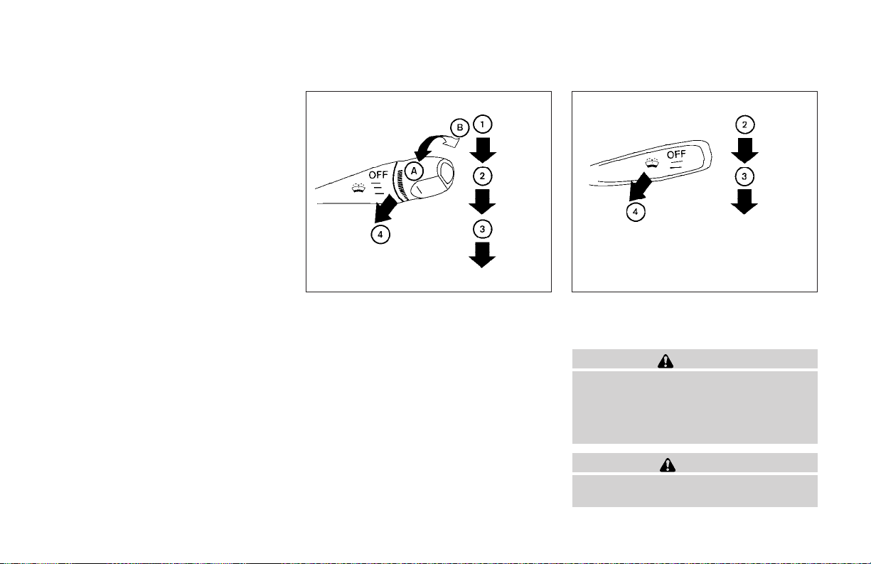
The hazard lights will quickly flash once and the
horn will sound once to confirm that the horn
beep feature has been reactivated.
Deactivating the horn feature does not silence
the horn if the alarm is triggered.
If the system does not operate asdescribed
above, have it checkedby aNISSAN dealer.
WINDSHIELD WIPER AND WASHER
SWITCH
2-18 Instruments and controls
WIC0639
Type A
SWITCH OPERATION
The windshield wiper and washeroperates when
the ignition switch is in the ON position.
Push the lever down to operate the wiper at the
following speed:
1
Intermittent (if so equipped) — intermittent
s
operation can be adjusted by turning the
knob toward
2
Low — continuous low speed operation
s
3
High — continuous high speed operation
s
A
(Slower) or
s
s
B
(Faster).
WIC0640
Type B
4
Pull the lever toward you
washer. Thewiper willalso operateseveral times.
to operate the
s
WARNING
In freezing temperatures the washer solution may freeze on the windshield and
obscure your vision which may lead to an
accident. Warm the windshield with the
defroster before you wash the windshield.
CAUTION
● Do not operate the washer continuously for more than 30 seconds.
Page 85
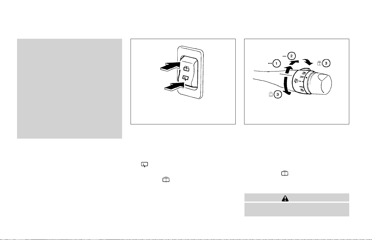
● Do not operate the washer if the reservoir tank is empty.
● Do not fill the window washer reservoir
tank with washer fluid concentrates at
full strength. Some methyl alcohol
based washer fluid concentrates may
permanently stain the grille if spilled
while filling the window washer reservoir tank.
● Pre-mix washer fluid concentrates with
water to the manufacturer’s recommended levels before pouring the fluid
into the window washer reservoir tank.
Do not use the window washer reservoir
tank to mix the washer fluid concentrate and water.
REAR WINDOW WIPER AND
WASHER SWITCH
WIC0326
Type A
The rear window wiper and washer operates
when the ignition switch is the ON position.
Type A
To operate the wiper, push the switch to
the
To operate the washer, push and hold the switch
down to the
twice.
Type B
Turn the switch clockwise from the OFF position
to operate the wiper.
side.
side. The wiper will cycle
LIC0634
Type B
1
Intermittent —intermittent operation(not ad-
s
justable)
2
Low — continuous low speed operation
s
3
Washer
s
You can also turn the switch counterclockwise tothe
washer. The wiper will also operate several
times.
position
3
to operatethe
s
CAUTION
● Do not operate the washer continuously for more than 30 seconds.
Instruments and controls 2-19
Page 86
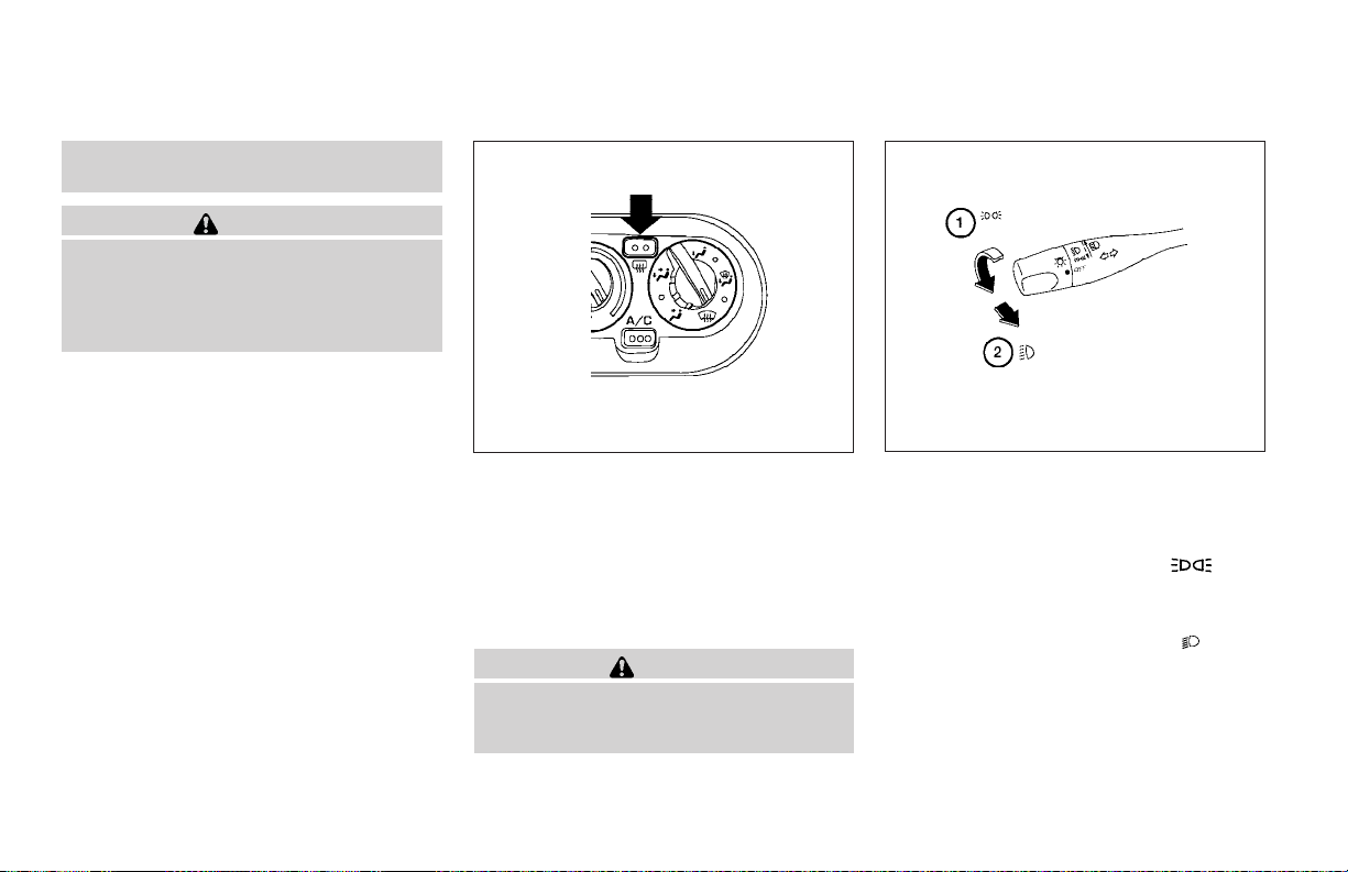
● Do not operate the washer if the reservoir tank is empty.
WARNING
In freezing temperatures the washer solution may freeze on the window and obscure your vision. Warm the rear window
with the defroster before you wash the
rear window.
REAR WINDOW DEFROSTER
SWITCH
HEADLIGHT AND TURN SIGNAL
SWITCH
2-20 Instruments and controls
WIC0327
Todefrost the rear window glass, start the engine
and push the rear window defroster switch on.
The rear window defroster indicator light on the
switch comes on. Push the switch again to turn
the defroster off.
The rear window defroster automatically turns off
after approximately 15 minutes.
CAUTION
When cleaning the inner side of the rear
window, be careful not to scratch or damage the rear window defroster.
WIC0242
Type A
HEADLIGHT CONTROL SWITCH
Lighting
1
When turning the switch to the posi-
s
tion, the front parking, tail, license plate and
instrument panel lights come on.
2
When turning the switch to the posi-
s
tion, theheadlights comeon andall theother
lights remain on.
Page 87
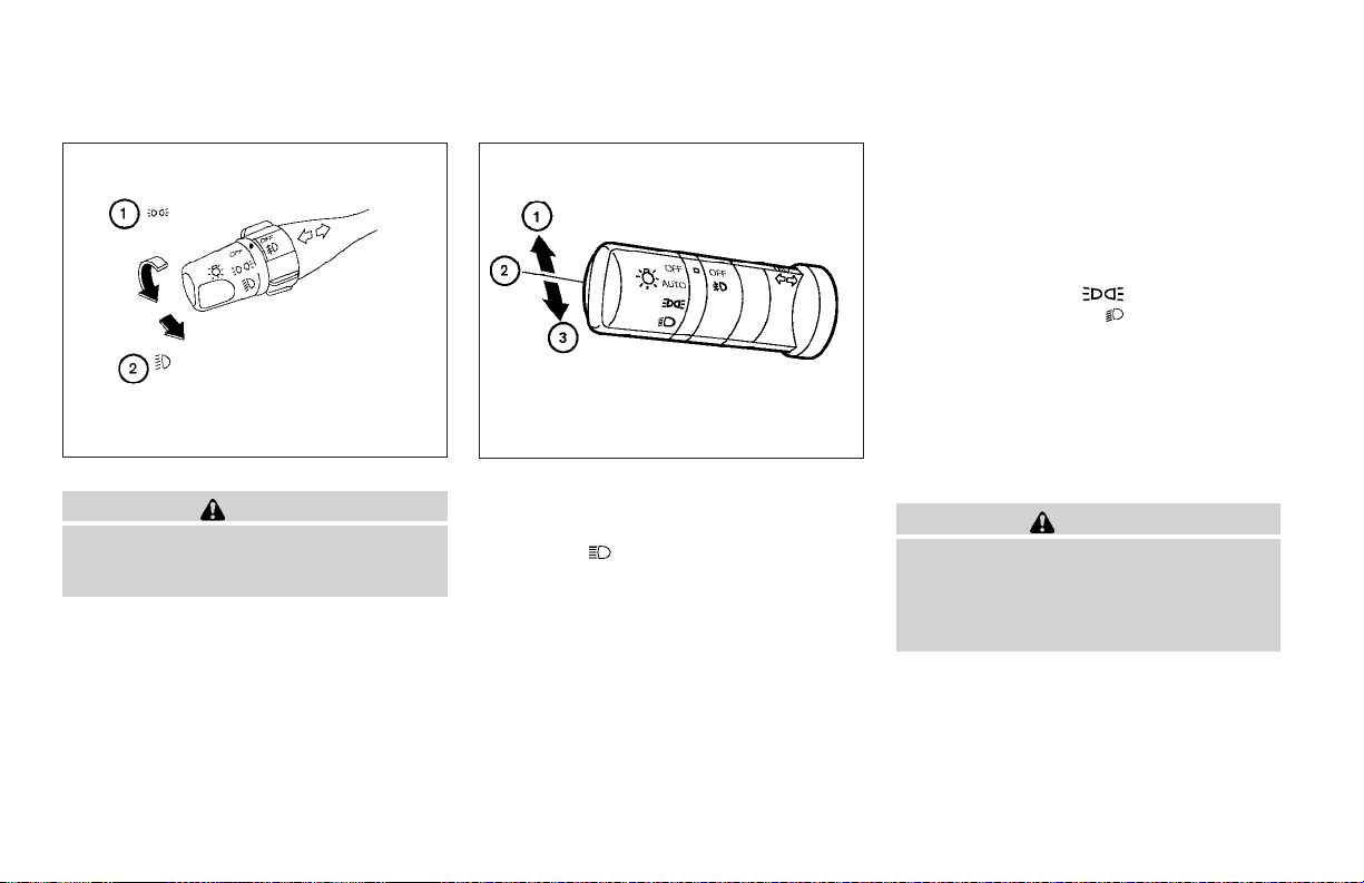
WIC0243
Type B
CAUTION
Use the headlights with the engine running to avoid discharging the vehicle
battery.
Headlight beam select
1
To select the high beam function, push the
s
lever forward. The high beam lights come on
and the
2
Pull the lever back to select the low beam.
s
3
Pulling and releasing the lever flashes the
s
headlight high beams on and off.
light illuminates.
LIC0562
DAYTIME RUNNING LIGHT SYSTEM
(Canada only)
The headlights automatically illuminate at a reduced intensity when the engine is started with
the parking brake released. The daytime running
lights operate with the headlight switch in the
OFF position or in the
headlight switch to the
illumination when driving at night.
If the parking brake is applied beforethe engineis
started, the daytime running lights do not illuminate. The daytime running lights illuminate when
the parking brake is released. The daytime running lights will remain on until the ignition switch
is turned off.
WARNING
When the daytime running light system is
active, tail lights on your vehicle are not
on. It is necessary at dusk to turn on your
headlights. Failure to do so could cause
an accident injuring yourself and others.
position. Turn the
position for full
Instruments and controls 2-21
Page 88
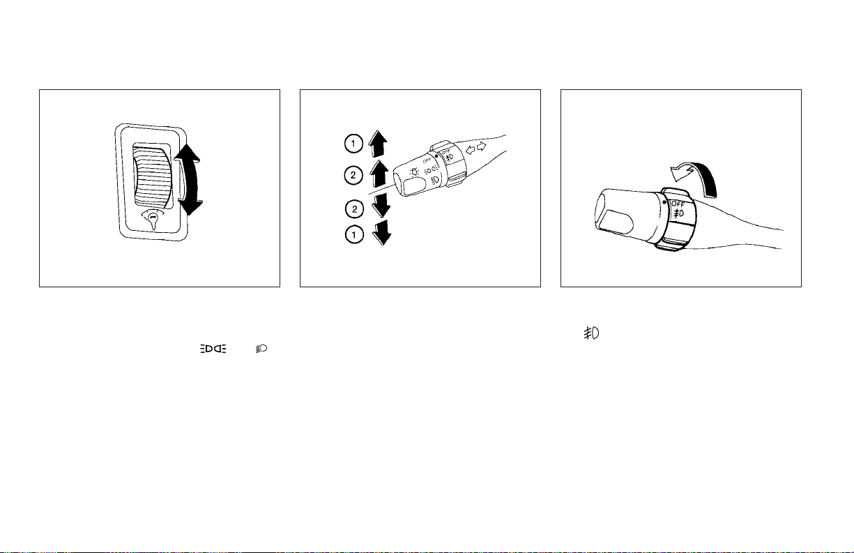
WIC0328 WIC0245 WIC0247
INSTRUMENT BRIGHTNESS
CONTROL
The instrument brightness control operates when
the headlight switch is in the
position.
Turnthe controlto adjust the brightness of instrument panel lights.
or
2-22 Instruments and controls
TURN SIGNAL SWITCH
Turn signal
1
Move the lever up or down to signal the
s
turning direction. When the turn is completed, the turn signals cancel automatically.
Lane change signal
2
Tosignal a lane change, move the lever up or
s
down to the point where the indicator light
begins to flash, but the lever does not latch.
FOG LIGHT SWITCH (if so equipped)
Toturn the front fog lights on, rotate the switch to
the
To turn them off, rotate the switch to the OFF
position.
The headlights must be on and the low beams
selected for the fog lights to operate. The fog
lights automatically turn off when the high beam
headlights are selected.
position.
Page 89
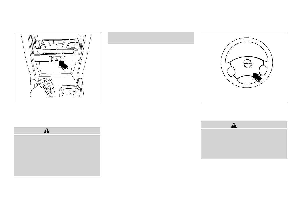
HAZARD WARNING FLASHER
SWITCH
HORN
● Turn signals do not work when the hazard warning flasher lights are on.
The flashers will operate with the ignition switch
in any position.
Some state laws may prohibit the use of
the hazard warning flasher switch while
driving.
WIC0329 WIC0249
Push the switch on to warn other drivers when
you must stop or park under emergency conditions. All turn signal lights flash.
WARNING
● When stalled or stopped on the roadway under emergency conditions, move
the vehicle well off the road.
● Do not use the hazard warning flashers
while moving on the highway unless
unusual circumstances force you to
drive so slowly that your vehicle might
become a hazard to other traffic.
To sound the horn, push the center pad area of
the steering wheel.
WARNING
Do not disassemble the horn. Doing so
could affect proper operation of the
supplemental front air bag system. Tampering with the supplemental front air bag
system may result in serious personal
injury.
Instruments and controls 2-23
Page 90
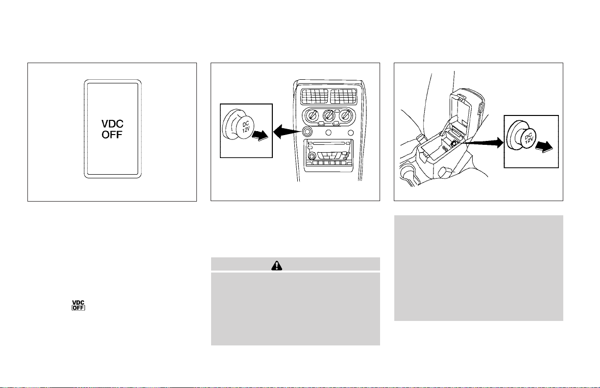
VEHICLE DYNAMIC CONTROL (VDC)
OFF SWITCH (if so equipped)
POWER OUTLET
WIC0534
The vehicle should be driven with the Vehicle
Dynamic Control (VDC) system on for most driving conditions.
If the vehicle is stuck in mud or snow, the VDC
system reduces the engine output to reduce
wheel spin. The engine speed will be reduced
even ifthe accelerator is depressed to the floor. If
maximum engine power is needed to free a stuck
vehicle, turn the VDC system off.
To turn off the VDC system, push the VDC OFF
switch. The
Push the VDC OFF switch again or restart the
engine to turn ON the system. See “Vehicle dynamic control (VDC) system” in the “Starting and
driving” section.
indicator will come on.
2-24 Instruments and controls
WIC0330
Front
The power outlets are for powering electrical
accessories such as cellular telephones. They
are rated at 12 Volt, 120W (10A) maximum.
CAUTION
● The outlet and plug may be hot during
or immediately after use.
● Only certainpower outletsare designed
for use with a cigarette lighter unit. Do
not use any other power outlet for an
accessory lighter. See your NISSAN
dealer for additional information.
WIC0331
Console
● Do not use with accessories that exceed a 12 volt, 120W (10A) power draw.
Do not use double adapters or more
than one electrical accessory.
● Use power outlets with the engine running to avoid discharging the vehicle
battery.
● Avoid using power outlets when the air
conditioner, headlights or rear window
defroster is on.
Page 91
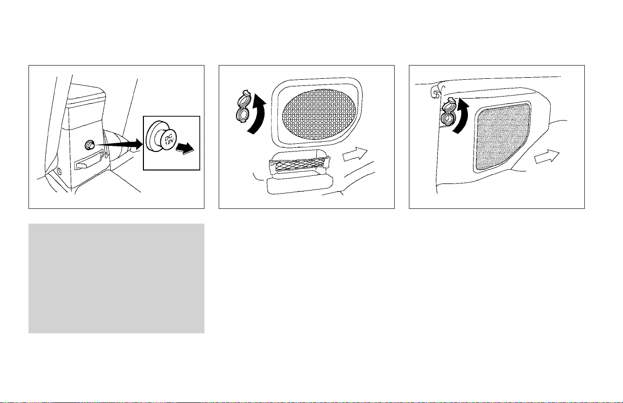
WIC0332
Rear
● Before inserting or disconnecting a
plug, be sure the electrical accessory
being used is turned OFF.
● Push the plug in as far as it will go. If
good contact is not made, the plug may
overheat or the internal temperature
fuse may open.
● When not in use, be sure to close the
cap. Do not allow water to contact the
outlet.
Rear cargo without subwoofer
(if so equipped)
WIC0429
LIC0430
Rear cargo with subwoofer
(if so equipped)
Instruments and controls 2-25
Page 92
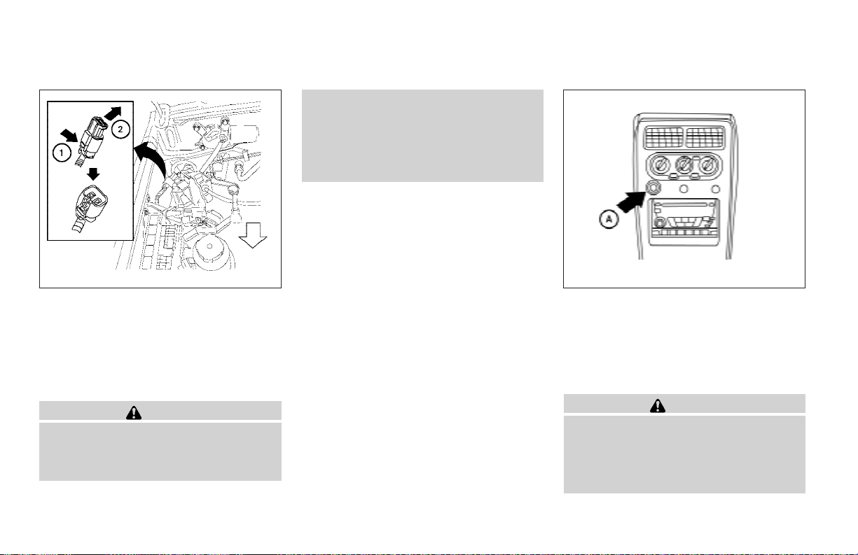
DUAL 12 VOLT POWER OUTLETS (if
so equipped)
LIC0598 WIC0735
The dual 12 volt power outlets can be used to
power optional add-on electrical devices.
To access the dual 12 volt power outlets, push in
the tab
The outlets are rated at 12 volt, 240W (20A)
maximum.
1
and remove the cover
s
s
2
.
CAUTION
● Do not use with accessories that exceed a 12 volt, 240W (20A) power draw.
Do not use double adapters or more
than one electrical accessory.
● Use power outlets with the engine running to avoid discharging the vehicle
battery.
● Avoid using power outlets when the air
conditioner, headlights or rear window
defroster is on.
CIGARETTE LIGHTER
A
This power outlet
sory cigarette lighter element. Contact your
NISSAN dealer for information.
This power outlet can also be used for powering
electrical accessories such as cellular telephones.
● The cigarette lighter should not be used
while driving so full attention may be
given to vehicle operation.
● The outlet and plug may be hot during
or immediately after use.
can be used with an acces-
s
CAUTION
2-26 Instruments and controls
Page 93
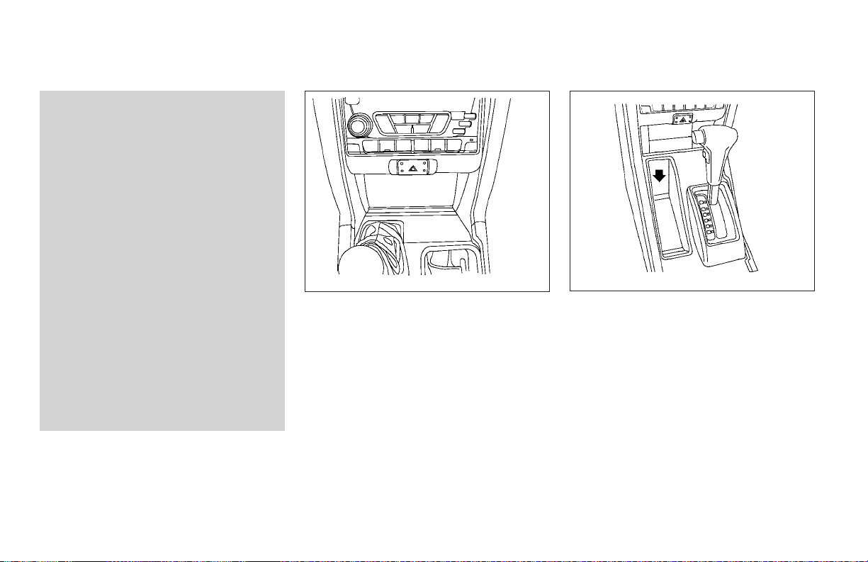
● Do notuse any other power outlet for an
accessory lighter.
● Do not use with accessories that exceed a 12 volt, 120W (10A) power draw.
Do not use double adapters or more
than one electrical accessory.
● Use power outlets with the engine running to avoid discharging the vehicle
battery.
● Avoid using power outlets when the air
conditioner, headlights or rear window
defroster is on.
● Before inserting or disconnecting a
plug, be sure the electrical accessory
being used is turned OFF.
● Push the plug in as far as it will go. If
good contact is not made, the plug may
overheat or the internal temperature
fuse may open.
● When not in use, be sure to close the
cap. Do not allow water to contact the
outlet.
STORAGE
WIC0334
STORAGE COMPARTMENT
A storage compartment is located in the center
bottom of the instrument panel.
LIC0635
Automatic transmission model
STORAGE TRAYS (if so equipped)
Instruments and controls 2-27
Page 94
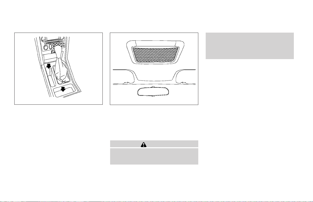
● Do not place sharp objects in the roof
headliner net. Such objects may become dangerous projectiles and cause
injury when the vehicle is moving or if
the vehicle is involved in a collision.
Manual transmission model
2-28 Instruments and controls
LIC0636
LIC0371
ROOF HEADLINER NET (if so
equipped)
The roofheadliner netcan be used to store paper
or small, lightweight objects that do not have
sharp edges.
WARNING
● The cargo restrained by the roof headliner net must not exceed 8 oz (230 g) or
the net may not stay secured.
Page 95
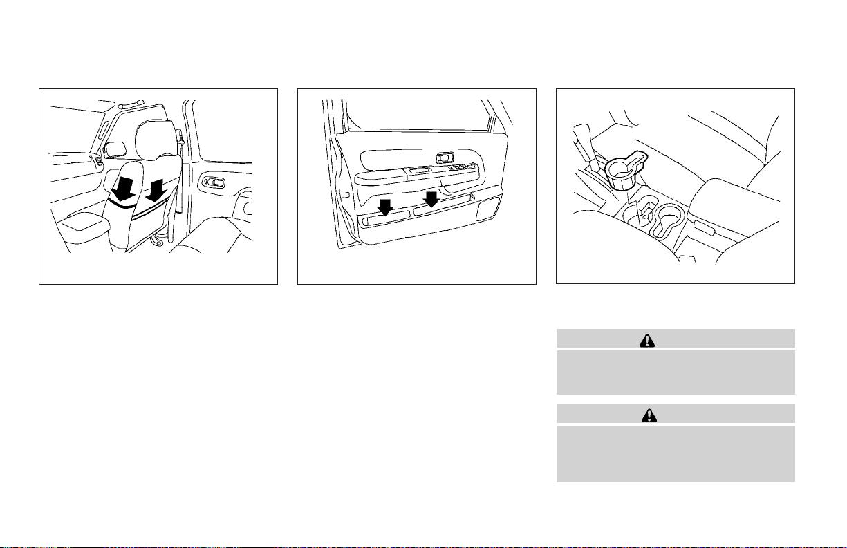
WIC0335 LIC0633
MAP POCKET
Map pockets are located on the side and back of
the passenger seat. They are also located on the
driver and front passenger doors.Themap pocket
can be used to store maps.
WIC0336
Front
CUP HOLDERS
WARNING
The cup holder should not be used while
driving so full attention may be given to
vehicle operation.
CAUTION
● Avoid abrupt starting and braking when
the cup holder is being used to prevent
spilling the drink. If the liquid is hot, it
can scald you or your passenger.
Instruments and controls 2-29
Page 96
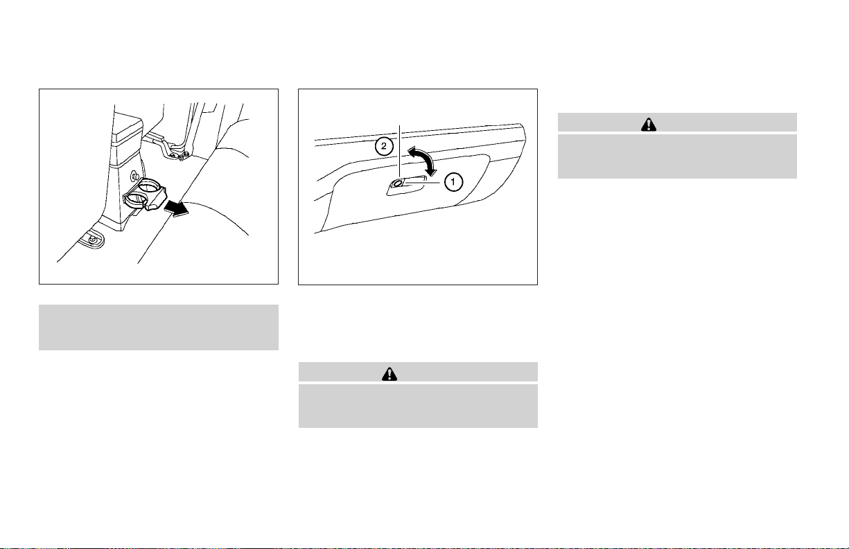
CONSOLE BOX (if so equipped)
WARNING
The center console box should not be
used whiledriving so full attention may be
given to vehicle operation.
WIC0337
Rear
● Use only soft cups in the cup holder.
Hard objects can injure you in an
accident.
The front cup holders have a rubber insert that
can be removed for cleaning and for using larger
cups.
To open the rear cup holder, pull out fully. To
close, push the cup holder in fully.
2-30 Instruments and controls
WIC0374
GLOVE BOX
Open the glove box by pulling the handle. When
locking
master key.
1
or unlocking
s
2
the glovebox, use the
s
WARNING
Keep glove box lid closed while driving to
help prevent injury in an accident or a
sudden stop.
Page 97
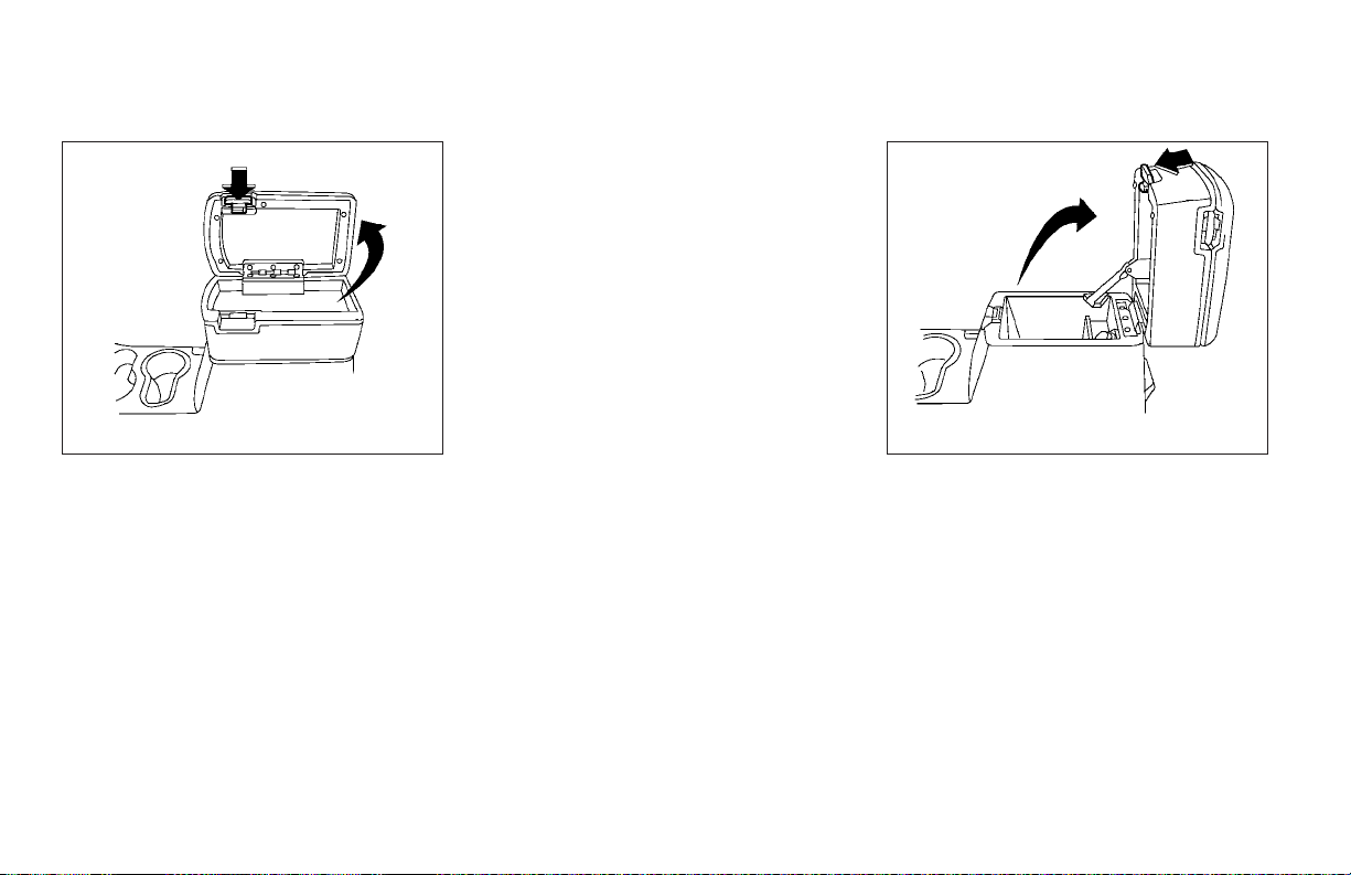
WIC0339 WIC0340
Upper half
Pull up on the lever to open the upper half of the
console box. The rubber mat may be removed for
cleaning.
The upper half of the console boxmay beused for
storage of cellular phones. An access hole is
provided at the bottom of the upper half of the
console box for phone cord routing to the power
outlet.
To route a phone cord to the power outlet:
1. Open the upper half of the console box.
2. Remove the rubber mat, and then remove
the cutout area from the mat.
3. Remove the access hole cover.
4. Install the rubber mat.
5. Route the phone cord through the access
hole and plug into the power outlet.
Lower half
Pull up on the lever to open the lower half of the
console box. A power outlet is located inside the
console box and there is storage for compact
discs.
LUGGAGE HOOKS
The tie down hooks can be used to secure cargo
with ropes or other types of straps.
Instruments and controls 2-31
Page 98
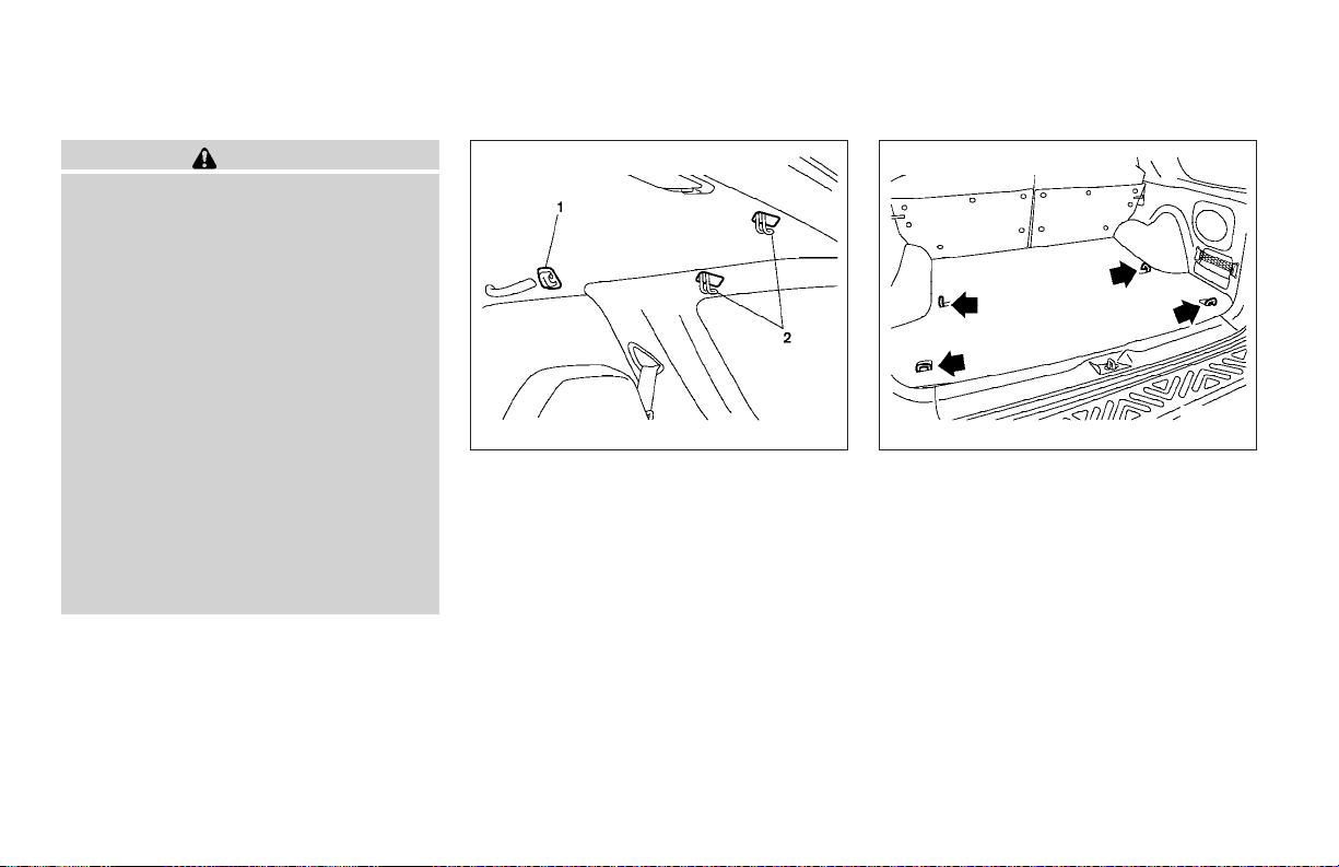
WARNING
● Properly secure all cargo with ropes or
straps to help prevent it from sliding or
shifting. Do not place cargo higher than
the seatbacks. In a sudden stop or collision, unsecured cargo could cause
personal injury.
● Use suitable ropes and hooks to secure
cargo.
● Never allow anyone to ride in the luggage area. It is extremely dangerous to
ride in a cargo area inside of a vehicle.
In a collision, people riding in these
areas are more likely to be seriously
injured or killed.
● Do not allow people to ride in any area
of your vehicle that is not equipped with
seats and seat belts.
● Be sure everyone in your vehicle is in a
seat and using a seat belt properly.
WIC0341 WIC0342
1. Plastic hook
2. Metal hook
Do not apply a total load of more than 33
lbs (15 kg) to a single plastic hook when
securing cargo.
Do not apply a total load of more than 110
lbs (50 kg) to a single metal hook when
securing cargo.
2-32 Instruments and controls
Page 99
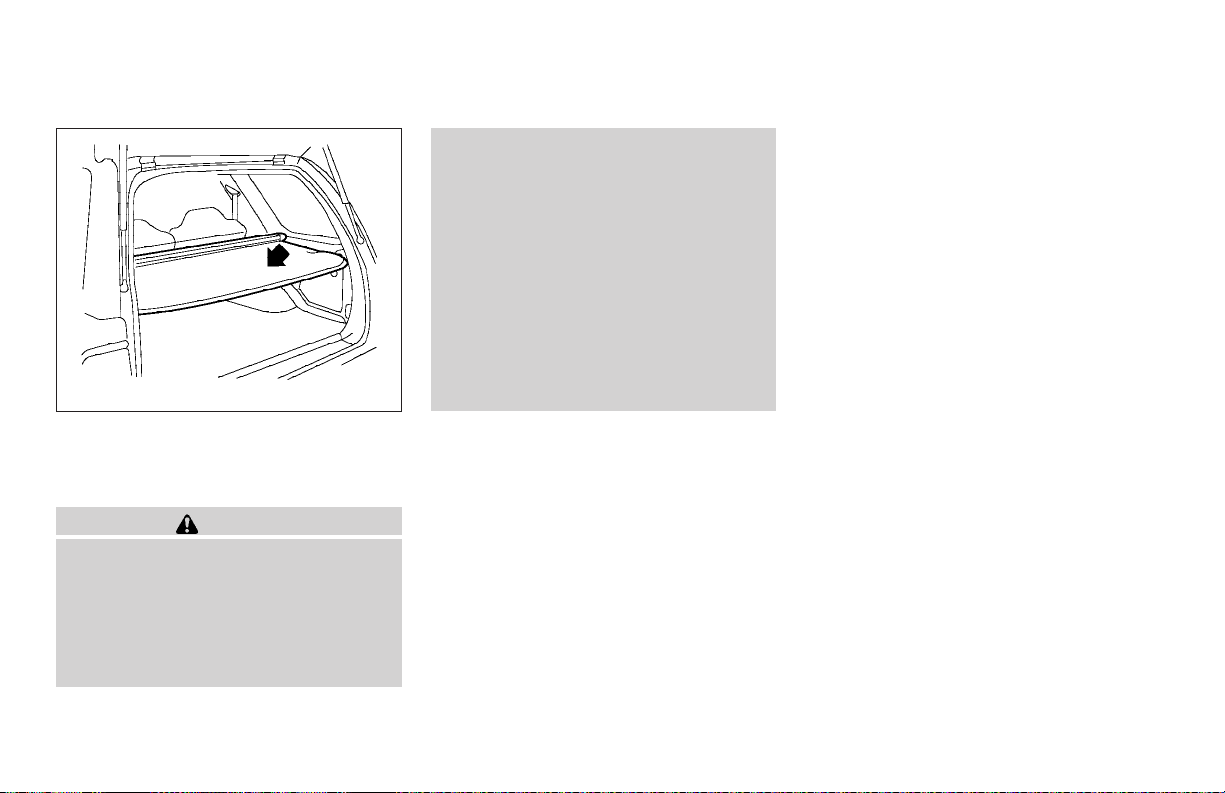
WIC0375
TONNEAU COVER (if so equipped)
The tonneau cover keeps the luggage compartment contents hidden from the outside.
WARNING
● Never put anything on the tonneau
cover, no matter how small. Any object
on it could cause an injury in an accident or sudden stop.
● Do not leave the tonneau cover in the
vehicle with it disengaged from the
holder.
● Properly secure all cargo with ropes or
straps to help prevent it from sliding or
shifting. Do not place cargo higher than
the seatbacks. In a sudden stop or collision, unsecured cargo could cause
personal injury.
● The child restraint top tether strap may
be damaged by contact with the tonneau cover or items in the cargo area.
Remove the tonneau cover from the vehicle or secure it and any cargo. Your
child could beseriously injured or killed
in a collision if the top tether strap is
damaged.
Instruments and controls 2-33
Page 100
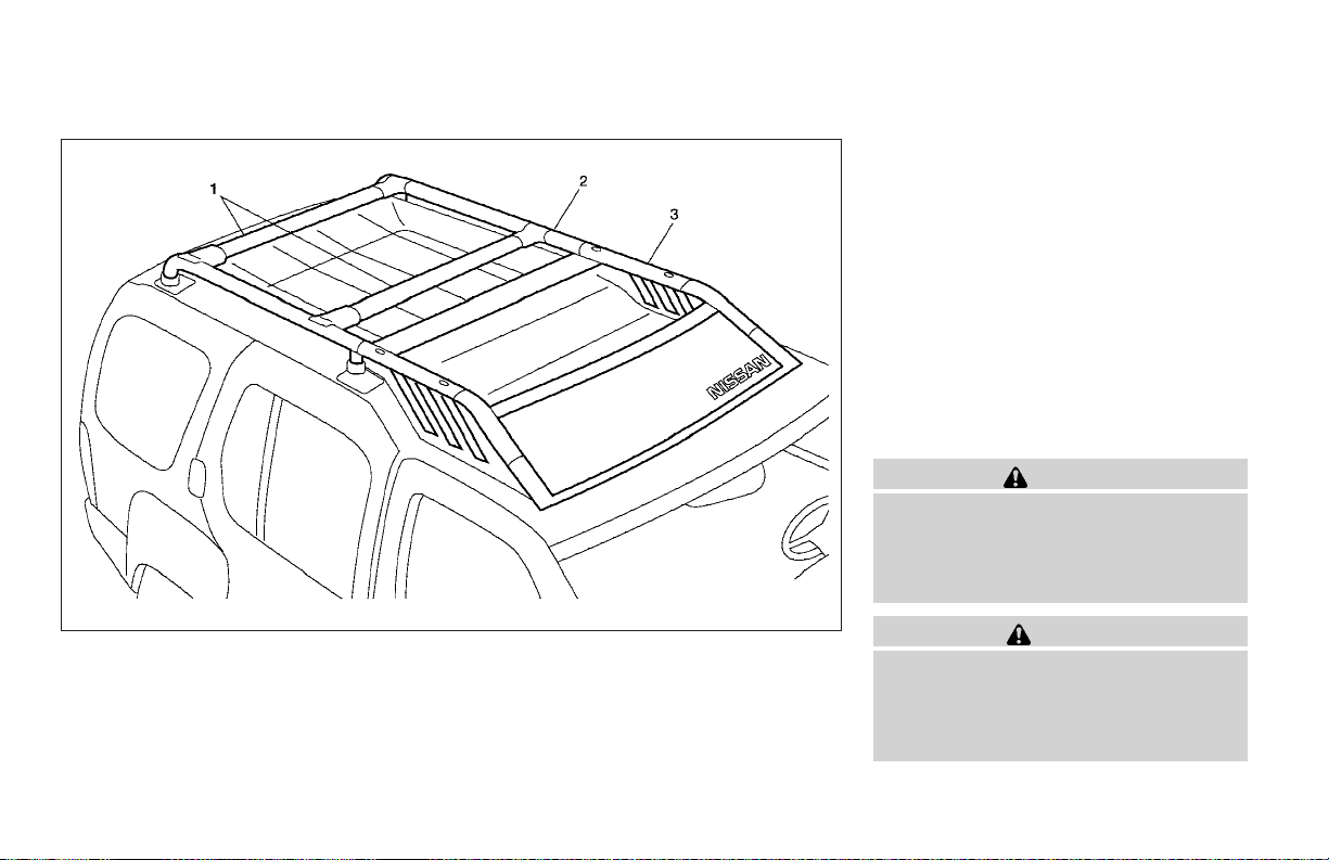
1. Adjustable crossbar
2. Tubular roof rack
3. Removable gear basket
WPD0162
TUBULAR ROOF RACK WITH GEAR
BASKET
Always evenly distribute the cargo on the tubular
roof rack. The maximum total load is 125 lb
(57 kg) evenly distributed, including gear
basket. Be careful that your vehicle does not
exceed the Gross Vehicle Weight Rating
(GVWR) or the Gross Axle Weight Ratings
(GAWR front and rear). The GVWR and GAWR
are located on the Safety Compliance Certification Label (located on the driver’s side door jamb
pillar). For more information regarding GVWR
and GAWR, refer to the “Technical and consumer information” section of this manual.
WARNING
Properly secure all cargo with ropes or
straps to help prevent it from sliding or
shifting. In a sudden stop or collision, unsecured cargo could cause personal
injury.
CAUTION
Use care when placing or removing items
from the tubular roof rack or gear basket.
If you cannot comfortably lift the items
onto the tubular roof rack or gear basket
from the ground, use a ladder or stool.
2-34 Instruments and controls
 Loading...