

Page 1
BRAKE SYSTEM
GI
MA
CONTENTS
PRECAUTIONS ...............................................................3
Supplemental Restraint System (SRS) ″AIR
BAG″ and ″SEAT BELT PRE-TENSIONER″...............3
Precautions for Brake System.....................................3
Wiring Diagrams and Trouble Diagnosis.....................3
PREPARATION ...............................................................4
Special Service Tools..................................................4
Commercial Service Tools...........................................4
NOISE, VIBRATION AND HARSHNESS (NVH)
TROUBLESHOOTING.....................................................5
NVH Troubleshooting Chart.........................................5
ON-VEHICLE SERVICE ..................................................6
Checking Brake Fluid Level.........................................6
Checking Brake Line ...................................................6
Changing Brake Fluid..................................................6
Brake Burnishing Procedure........................................7
Bleeding Brake System...............................................8
BRAKE HYDRAULIC LINE.............................................9
Hydraulic Circuit...........................................................9
Removal.......................................................................9
Inspection...................................................................10
Installation..................................................................10
BRAKE PEDAL AND BRACKET..................................11
Removal and Installation...........................................11
Inspection...................................................................11
Adjustment.................................................................12
MASTER CYLINDER.....................................................13
Removal.....................................................................13
Disassembly...............................................................13
Inspection...................................................................14
Assembly ...................................................................14
Installation..................................................................15
BRAKE BOOSTER........................................................16
On-vehicle Service.....................................................16
OPERATING CHECK
AIRTIGHT CHECK
Removal.....................................................................16
Inspection...................................................................16
OUTPUT ROD LENGTH CHECK
...............................................16
...................................................16
..............................16
SECTION
Installation..................................................................17
VACUUM PIPING...........................................................18
Removal and Installation...........................................18
Inspection...................................................................18
HOSES AND CONNECTORS
CHECK VALVE
FRONT DISC BRAKE ...................................................19
Pad Replacement......................................................19
Removal.....................................................................20
Disassembly...............................................................20
Inspection...................................................................21
CALIPER
ROTOR
Assembly ...................................................................22
Installation..................................................................22
Brake Burnishing Procedure......................................22
REAR DRUM BRAKE ...................................................23
Components...............................................................23
Removal.....................................................................23
Inspection...................................................................24
WHEEL CYLINDER
Wheel Cylinder Overhaul...........................................24
Inspection...................................................................25
.....................................................................25
DRUM
....................................................................25
LINING
Installation..................................................................25
PARKING BRAKE CONTROL......................................27
Components...............................................................27
Removal and Installation...........................................27
Inspection...................................................................27
Adjustment.................................................................28
DESCRIPTION...............................................................29
Purpose......................................................................29
Operation...................................................................29
ABS Hydraulic Circuit................................................29
System Components .................................................30
System Description....................................................30
........................................................18
.................................................................21
...................................................................21
BR
...................................18
..................................................24
ABS
EM
LC
EC
FE
CL
MT
AT
TF
PD
AX
SU
ST
RS
BT
HA
SC
EL
IDX
Page 2

CONTENTS (Cont’d)
WHEEL SENSOR
CONTROL UNIT (BUILT-IN ABS ACTUATOR AND
ELECTRIC UNIT)
ABS ACTUATOR AND ELECTRIC UNIT
G SENSOR (4WD MODELS)
....................................................30
.....................................................30
....................31
....................................31
Component Parts and Harness Connector
Location .....................................................................32
Schematic..................................................................33
2–WHEEL DRIVE
4–WHEEL DRIVE
....................................................33
....................................................34
Wiring Diagram - ABS - 2WD - .................................35
Wiring Diagram - ABS - 4WD - .................................38
ON BOARD DIAGNOSTIC SYSTEM
DESCRIPTION...............................................................41
Self-diagnosis ............................................................41
FUNCTION
SELF-DIAGNOSIS PROCEDURE
HOW TO READ SELF-DIAGNOSTIC RESULTS
(MALFUNCTION CODES)
HOW TO ERASE SELF-DIAGNOSTIC RESULTS
(MALFUNCTION CODES)
..............................................................41
..............................41
........................................42
........................................42
TROUBLE DIAGNOSIS - INTRODUCTION..................43
How to Perform Trouble Diagnoses for Quick
and Accurate Repair..................................................43
INTRODUCTION
......................................................43
TROUBLE DIAGNOSIS - BASIC INSPECTION...........44
Preliminary Check......................................................44
Ground Circuit Check................................................47
ABS ACTUATOR AND ELECTRIC UNIT GROUND
.....47
TROUBLE DIAGNOSIS - GENERAL
DESCRIPTION...............................................................48
Malfunction Code/Symptom Chart.............................48
TROUBLE DIAGNOSES FOR SELF-DIAGNOSTIC
ITEMS.............................................................................49
Wheel Sensor or Rotor..............................................49
DIAGNOSTIC PROCEDURE
.....................................49
ABS Actuator Solenoid Valve or Solenoid Valve
Relay..........................................................................52
DIAGNOSTIC PROCEDURE
.....................................52
Motor Relay or Motor.................................................54
DIAGNOSTIC PROCEDURE
.....................................54
Low Voltage...............................................................56
DIAGNOSTIC PROCEDURE
.....................................56
G Sensor and Circuit.................................................58
DIAGNOSTIC PROCEDURE
.....................................58
Control Unit................................................................60
DIAGNOSTIC PROCEDURE
.....................................60
TROUBLE DIAGNOSES FOR SYMPTOMS.................61
1. ABS Works Frequently ..........................................61
2. Unexpected Pedal Action ......................................61
3. Long Stopping Distance........................................63
4. ABS Does Not Work..............................................63
5. Pedal Vibration and Noise.....................................64
6. Warning Lamp Does Not Come On When
Ignition Switch Is Turned On .....................................64
7. Warning Lamp Stays On When Ignition Switch
Is Turned On..............................................................66
REMOVAL AND INSTALLATION.................................69
Front Wheel Sensor...................................................69
Rear Wheel Sensor...................................................69
4WD MODELS
2WD MODELS
.........................................................69
.........................................................70
Front Sensor Rotor....................................................70
REMOVAL
INSTALLATION
...............................................................70
........................................................71
Rear Sensor Rotor (4WD).........................................71
REMOVAL
INSTALLATION
...............................................................71
........................................................71
Rear Sensor Rotor (2WD).........................................71
REMOVAL AND INSTALLATION
...............................71
G Sensor....................................................................71
ABS Actuator and Electric Unit..................................72
REMOVAL
INSTALLATION
...............................................................72
........................................................72
SERVICE DATA AND SPECIFICATIONS (SDS).........73
General Specifications...............................................73
Disc Brake .................................................................73
Drum Brake................................................................73
Brake Pedal...............................................................73
Parking Brake Control ...............................................74
BR-2
Page 3
PRECAUTIONS
Supplemental Restraint System (SRS) “AIR BAG” and “SEAT BELT PRE-TENSIONER”
Supplemental Restraint System (SRS) “AIR
BAG” and “SEAT BELT PRE-TENSIONER”
The supplemental Restraint System such as “AIR BAG” and “SEAT BELT PRE-TENSIONER” used along with
a seat belt, helps to reduce the risk or severity of injury to the driver and front passenger for certain types of
collision. The Supplemental Restraint System consists of driver air bag module (located in the center of the
steering wheel), front passenger air bag module (located on the instrument panel on passenger side), seat
belt pre-tensioners, a diagnosis sensor unit, a crash zone sensor (4WD models), warning lamp, wiring harness and spiral cable.
Information necessary to service the system safely is included in the RS section of this Service Manual.
WARNING:
I To avoid rendering the SRS inoperative, which could increase the risk of personal injury or death
in the event of a collision which would result in air bag inflation, all maintenance must be performed
by an authorized NISSAN dealer.
I Improper maintenance, including incorrect removal and installation of the SRS, can lead to per-
sonal injury caused by unintentional activation of the system. For removal of Spiral Cable and Air
Bag Module, refer to
I Do not use electrical test equipment on any circuit related to the SRS unless instructed to in this
Service Manual. Spiral cable and wiring harnesses (except “SEAT BELT PRE-TENSIONER”) covered with yellow insulation either just before the harness connectors or for the complete harness
are related to the SRS.
RS-16
.
NGBR0001
GI
MA
EM
LC
EC
FE
CL
SBR686C
Precautions for Brake System
I Use brake fluid “DOT 3”.
I Never reuse drained brake fluid.
I Be careful not to splash brake fluid on painted areas; it
may cause paint damage. If brake fluid is splashed on
painted areas, wash it away with water immediately.
I To clean master cylinder parts, disc brake caliper parts or
wheel cylinder parts, use clean brake fluid.
I Never use mineral oils such as gasoline or kerosene. They
will ruin rubber parts of hydraulic system.
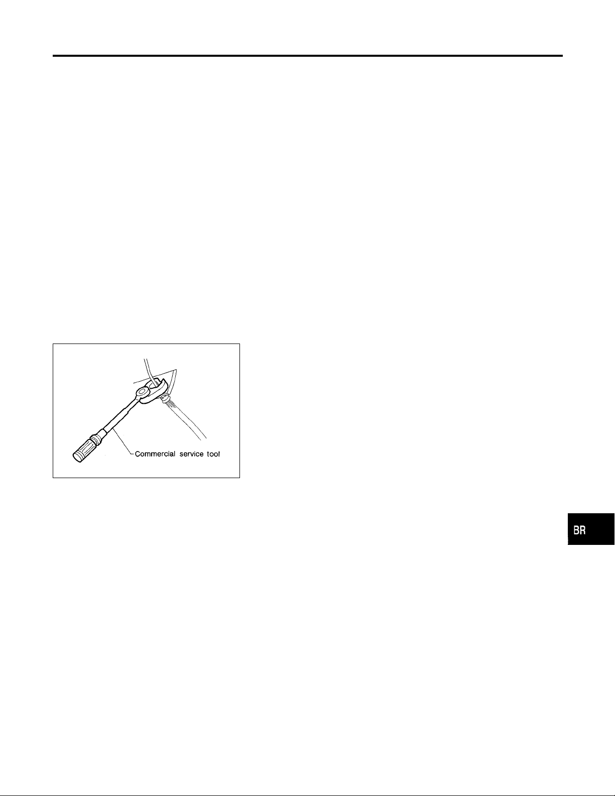
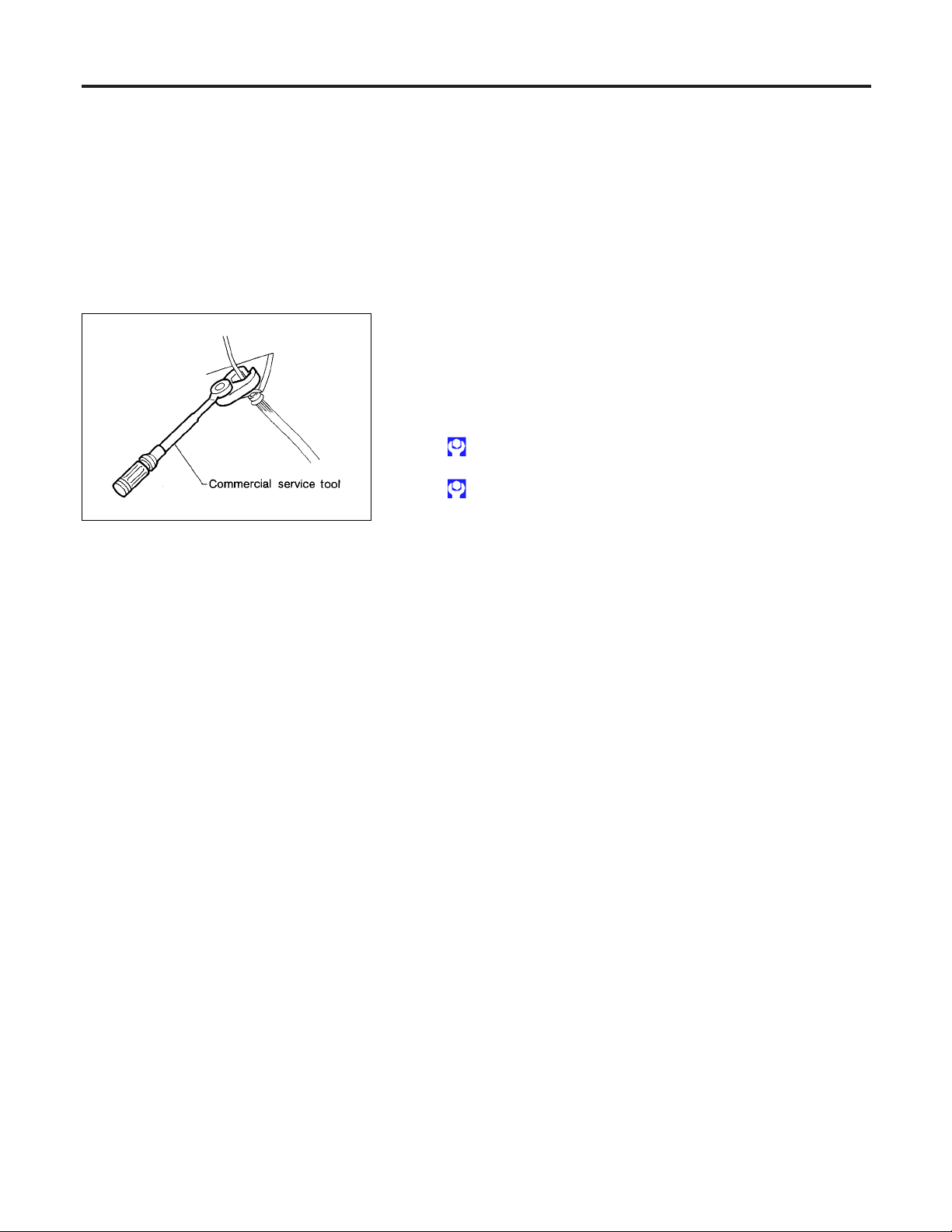
I Use flare nut wrench when removing and installing brake
tubes.
I Always torque brake lines when installing.
WARNING:
I Clean brakes with a vacuum dust collector to minimize
risk of health hazard from powder caused by friction.
NGBR0002
MT
AT
TF
PD
AX
SU
ST
RS
Wiring Diagrams and Trouble Diagnosis
When you read wiring diagrams, refer to the followings:
GI-10
I “HOW TO READ WIRING DIAGRAMS” refer to
I “POWER SUPPLY ROUTING” for power distribution circuit refer to
When you perform trouble diagnosis, refer to the followings:
I “HOW TO FOLLOW TEST GROUP IN TROUBLE DIAGNOSIS” refer to
I “HOW TO PERFORM EFFICIENT DIAGNOSIS FOR AN ELECTRICAL INCIDENT” refer to
.
EL-9
.
GI-34
.
BR-3
GI-23
NGBR0003
.
BT
HA
SC
EL
IDX
Page 4
Special Service Tools
PREPARATION
Special Service Tools
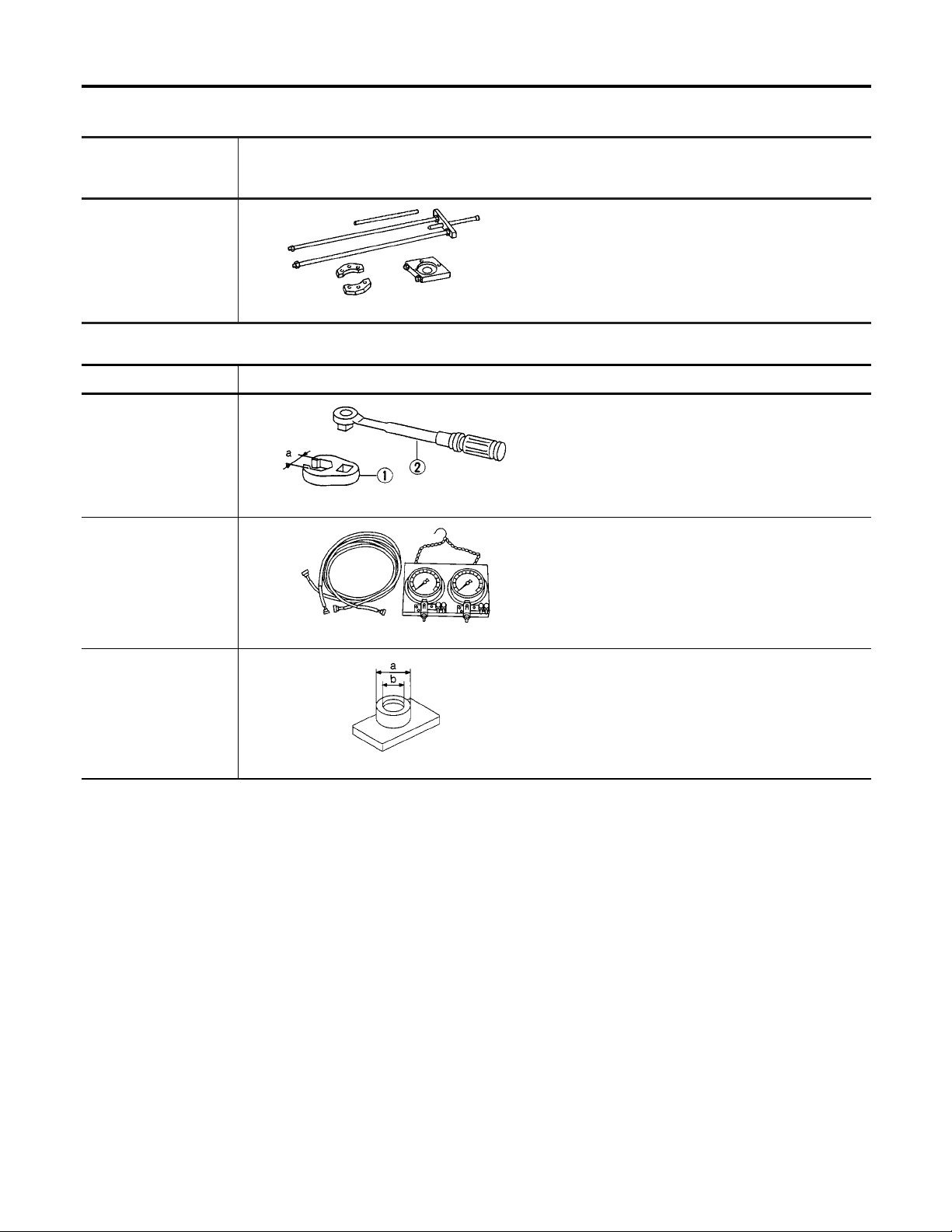
The actual shapes of Kent-Moore tools may differ from those of special service tools illustrated here.
Tool number
(Kent-Moore No.)
Tool name
KV40106500
(JS25852-B)
Wheel bearing puller
Description
Removing rear wheel sensor rotor
NT724
Commercial Service Tools
Tool name Description
1 Flare nut crowfoot
2 Torque wrench
NT360
Brake fluid pressure
gauge
Removing and installing each brake piping
a: 10 mm (0.39 in)
Measuring brake fluid pressure
NGBR0004
NGBR0005
Rear wheel sensor
rotor drift
NT151
Installing rear wheel sensor rotor
a: 75 mm (2.95 in) dia.
b: 63 mm (2.48 in) dia.
NT509
BR-4
Page 5
NOISE, VIBRATION AND HARSHNESS (NVH) TROUBLESHOOTING
NVH Troubleshooting Chart
NGBR0085
NVH Troubleshooting Chart
NGBR0085S01
Use the chart below to help you find the cause of the symptom. If necessary, repair or replace these parts.
,
PD-40
,
Reference page
Possible cause
and SUSPECTED PARTS
Noise ×××× Ч Ч ЧЧЧЧЧЧ
BR-25
BR-19, 25
Linings or pads - damaged
Linings or pads - uneven wear
BR-23
BR-18
Return spring damaged
Shims damaged
—
—
Rotor or drum imbalance
Rotor or drum damage
—
BR-21, 25
Rotor or drum runout
Rotor or drum deformation
—
—
Rotor or drum deflection
Rotor or drum rust
BR-21
BR-25
Rotor thickness variation
Drum out of round
.
PD-4
PD-14
NVH,
NVH,
PROPELLER SHAFT
.
.
.
AX-3
AX-3
NVH,
NVH,
PD-62
DIFFERENTIAL
DRIVE SHAFT
AXLE
.
.
.
SU-3
SU-3
SU-3
NVH,
NVH,
NVH,
SUSPENSION
TIRES
ROAD WHEEL
GI
MA
.
ST-5
EM
NVH,
LC
EC
FE
CL
STEERING
MT
Symptom BRAKE
×: Applicable
Shake × × ЧЧЧЧЧЧ
Shimmy, Judder ЧЧЧЧЧЧЧЧ ЧЧЧЧЧ
AT
TF
PD
AX
SU
ST
RS
BT
BR-5
HA
SC
EL
IDX
Page 6
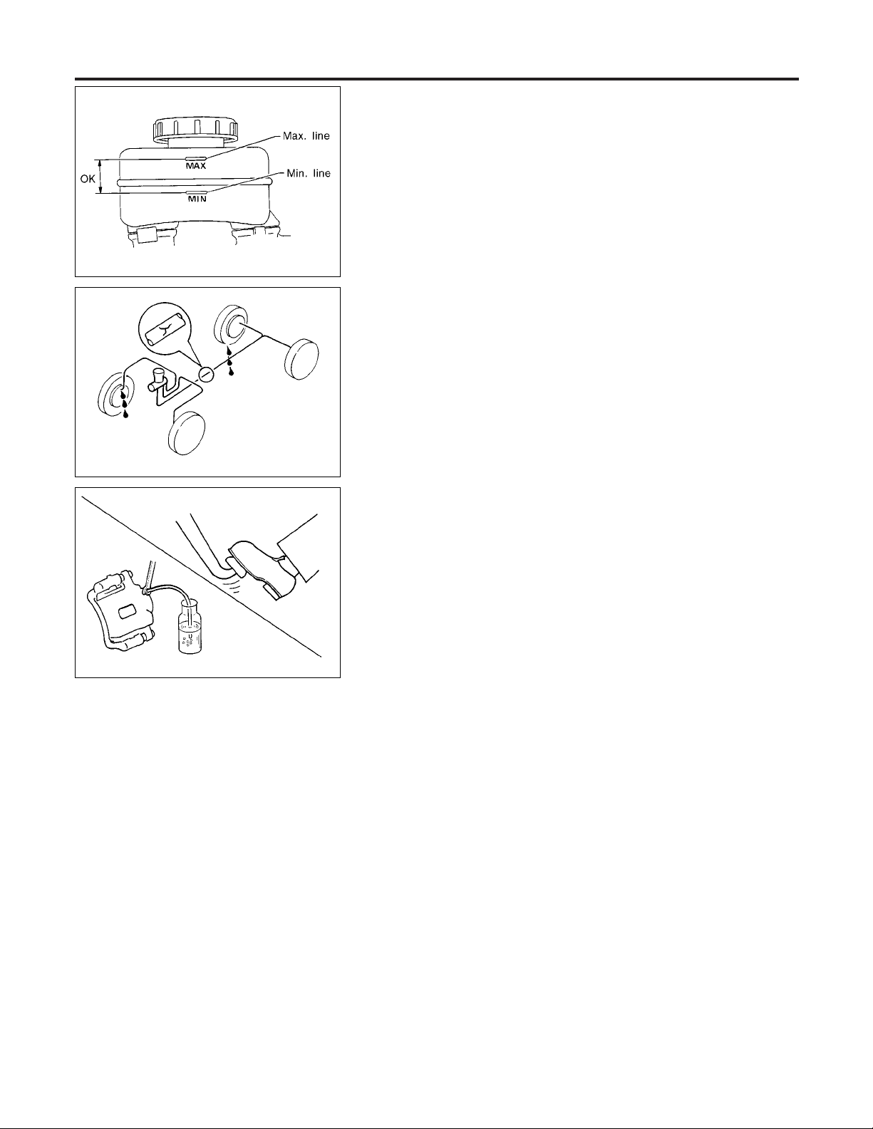
Checking Brake Fluid Level
ON-VEHICLE SERVICE
SBR451D
SBR389C
SBR419C
Checking Brake Fluid Level
NGBR0006
I Check fluid level in reservoir tank. It should be between Max
and Min lines on reservoir tank.
I If fluid level is extremely low, check brake system.
I If the brake warning lamp comes on, check brake fluid level
switch and parking brake switch.
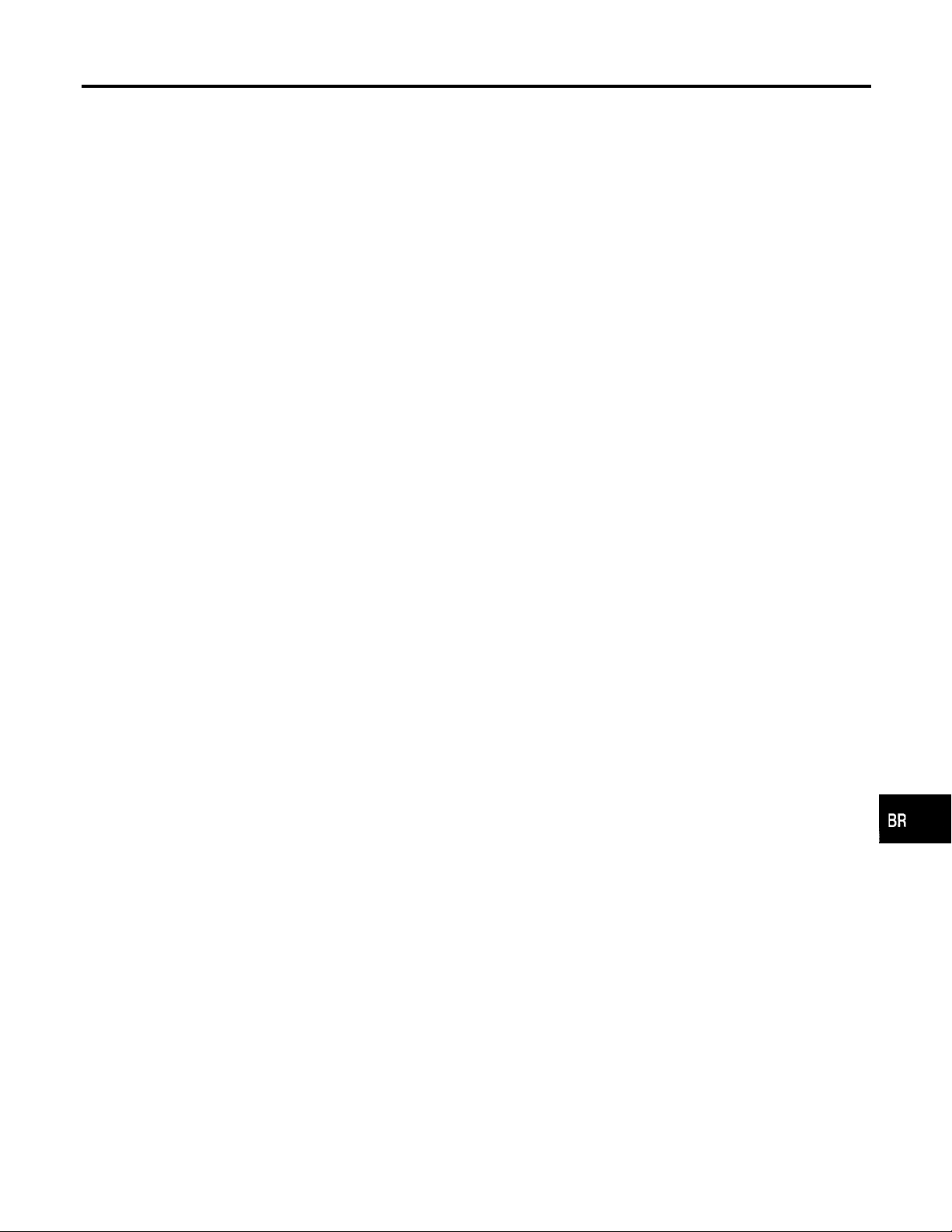
Checking Brake Line
NGBR0007
CAUTION:
If leakage occurs around joints, retighten or, if necessary,
replace damaged parts.
1. Check brake lines (tubes and hoses) for cracks, deterioration
and other damage. Replace any damaged parts.
2. Check for oil leakage by fully depressing brake pedal while
engine is running.
Changing Brake Fluid
NGBR0008
CAUTION:
I Refill with new brake fluid “DOT 3”.
I Always keep fluid level higher than minimum line on res-
ervoir tank.
I Never reuse drained brake fluid.
I Be careful not to splash brake fluid on painted areas; it
may cause paint damage. If brake fluid is splashed on
painted areas, wash it away with water immediately.
1. Clean inside of reservoir tank, and refill with new brake fluid.
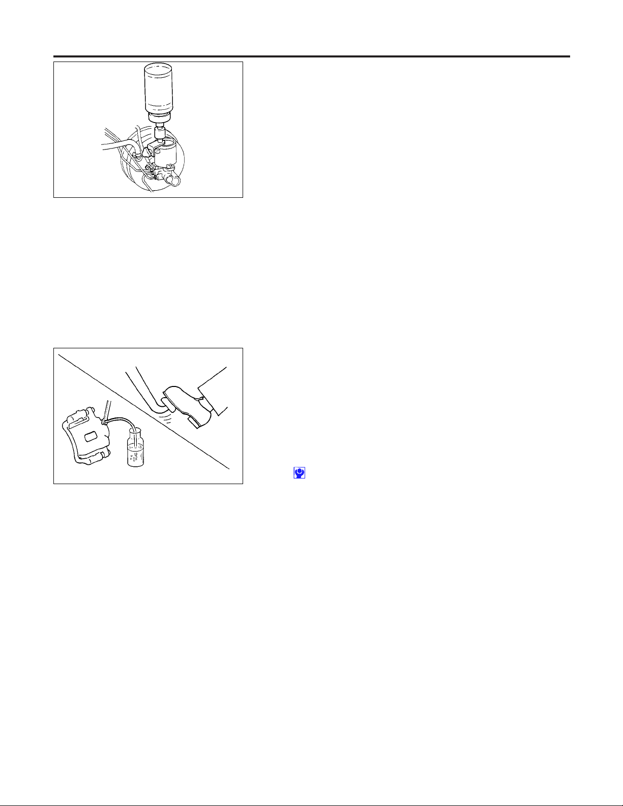
2. Connect a vinyl tube to each air bleeder valve.
3. Drain brake fluid from each air bleeder valve by depressing
brake pedal.
4. Refill until brake fluid comes out of each air bleeder valve.
Use same procedure as in bleeding hydraulic system to refill
brake fluid.
Refer to “Bleeding Brake System”, BR-8.
BR-6
Page 7
ON-VEHICLE SERVICE
Brake Burnishing Procedure
Brake Burnishing Procedure
Burnish the brake contact surfaces according to the following procedure after refinishing or replacing drums or rotors, after replacing pads or linings, or if a soft pedal occurs at very low mileage.
CAUTION:
Only perform this procedure under safe road and traffic conditions. Use extreme caution.
1. Drive the vehicle on a straight smooth road at 50 km/h (31
MPH).
2. Use medium brake pedal/foot effort to bring the vehicle to a
pressure such that vehicle stopping time equals to 3 to 5 sec-
onds.
3. To cool the brake system, drive the vehicle at 50 km/h (31
MPH) for 1 minute without stopping.
4. Repeat steps 1 to 3, 10 times or more to complete the burnish-
ing procedure.
=NGBR0120
GI
MA
EM
LC
EC
FE
CL
MT
AT
TF
PD
AX
SU
ST
RS
BT
BR-7
HA
SC
EL
IDX
Page 8
Bleeding Brake System
ON-VEHICLE SERVICE
SBR995
SBR419C
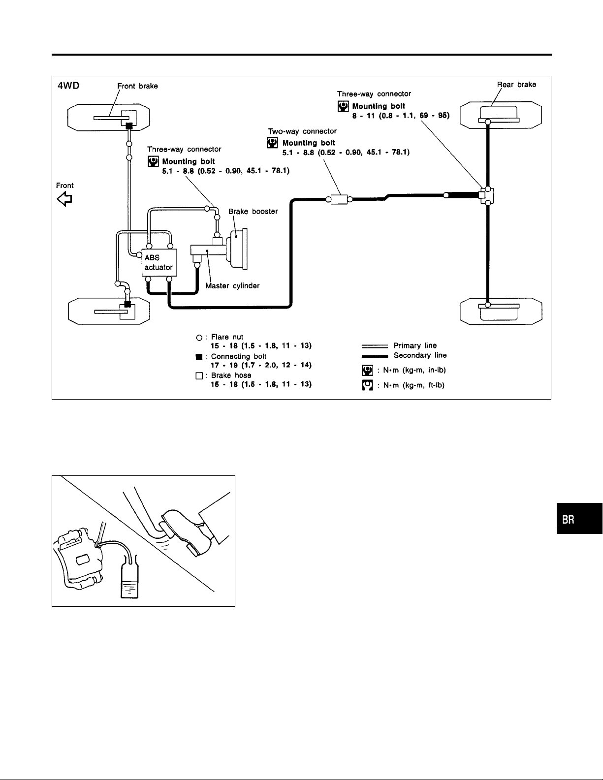
Bleeding Brake System
=NGBR0009
CAUTION:
I Carefully monitor brake fluid level at master cylinder dur-
ing bleeding operation.
I If master cylinder is suspected to have air inside, bleed air
from master cylinder first. Refer to “Installation”, “MAS-
TER CYLINDER”, BR-15.
I Fill reservoir with new brake fluid “DOT 3”. Make sure it is
full at all times while bleeding air out of system.
I Place a container under master cylinder to avoid spillage
of brake fluid.
I Turn ignition switch OFF and disconnect ABS actuator
connectors or battery ground cable.
I Bleed air in the following order.
1. Left rear brake
2. Right rear brake
3. Left front brake
4. Right front brake
1. Connect a transparent vinyl tube to air bleeder valve.
2. Fully depress brake pedal several times.
3. With brake pedal depressed, open air bleeder valve to release
air.
4. Close air bleeder valve.
5. Release brake pedal slowly.
6. Repeat steps 1. through 4. until clear brake fluid comes out of
air bleeder valve.
7. Tighten air bleeder valve to specified torque.
:7-9N·m(0.7 - 0.9 kg-m, 61 - 78 in-lb)
BR-8
Page 9
BRAKE HYDRAULIC LINE
Hydraulic Circuit
Hydraulic Circuit
NGBR0010
GI
MA
EM
LC
EC
FE
CL
MT
SBR992
ABR676
Removal
CAUTION:
I Be careful not to splash brake fluid on painted areas; it
may cause paint damage. If brake fluid is splashed on
painted areas, wash it away with water immediately.
I All hoses must be free from excessive bending, twisting
and pulling.
1. Connect vinyl tube to air bleeder valve.
2. Drain brake fluid from each air bleeder valve by depressing
brake pedal.
3. Remove flare nut connecting brake tube and hose, then with-
draw lock spring.
4. Cover openings to prevent entrance of dirt whenever discon-
necting brake line.
NGBR0011
AT
TF
PD
AX
SU
ST
RS
BT
HA
BR-9
SC
EL
IDX
Page 10
Inspection
BRAKE HYDRAULIC LINE
SBR686C
Inspection
NGBR0012
Check brake lines (tubes and hoses) for cracks, deterioration and
other damage. Replace any damaged parts.
Installation
NGBR0013
CAUTION:
I Refill with new brake fluid “DOT 3”.
I Never reuse drained brake fluid.
1. Tighten all flare nuts and connecting bolts.
Flare nut:
: 15 - 17 N·m (1.5 - 1.8 kg-m, 11 - 13 ft-lb)
Connecting bolt:
: 17 - 19 N·m (1.7 - 2.0 kg-m, 12 - 14 ft-lb)
2. Refill until new brake fluid comes out of each air bleeder valve.
3. Bleed air. Refer to “Bleeding Brake System”, BR-8.
BR-10
Page 11
BRAKE PEDAL AND BRACKET
Removal and Installation
Removal and Installation
NGBR0016
GI
MA
EM
LC
EC
FE
CL
MT
SBR997
Inspection
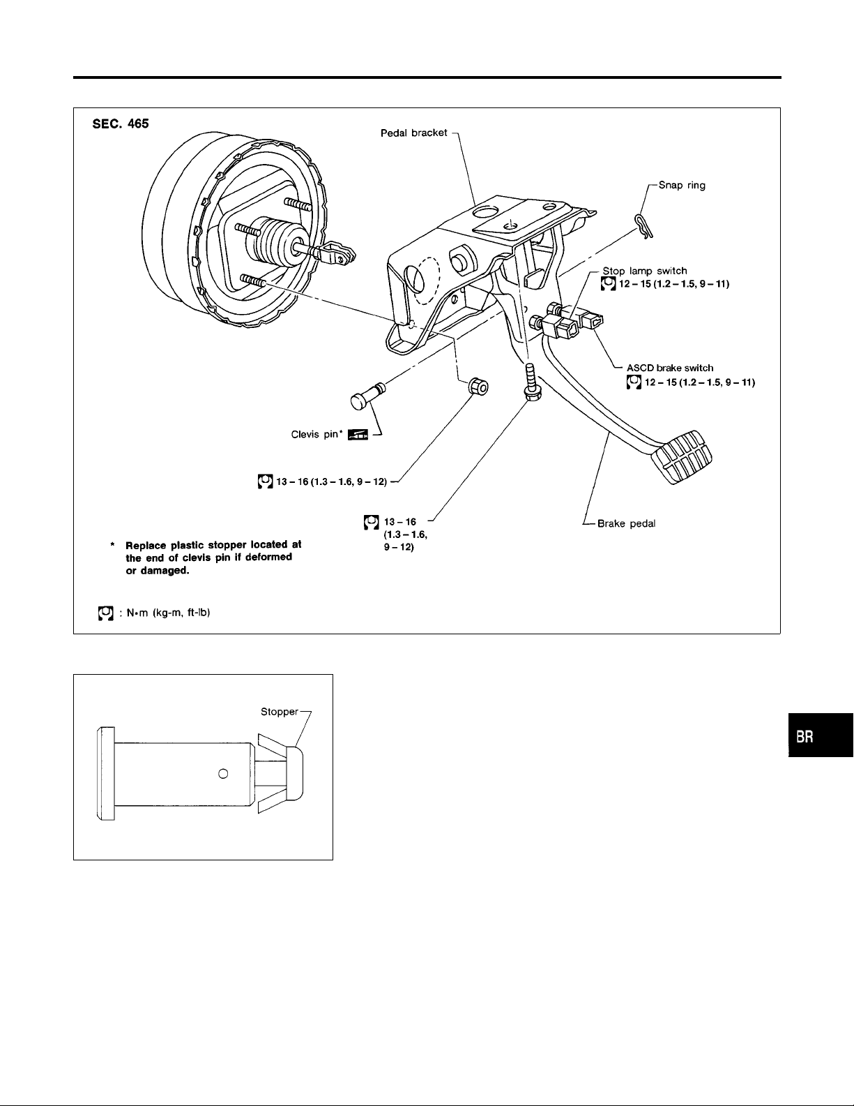
Check brake pedal for following items.
I Brake pedal bend
I Clevis pin deformation
I Crack of any welded portion
I Crack or deformation of clevis pin stopper
ABR824
NGBR0017
AT
TF
PD
AX
SU
ST
RS
BT
BR-11
HA
SC
EL
IDX
Page 12
Adjustment
BRAKE PEDAL AND BRACKET
SBR278AB
SBR930
Adjustment
NGBR0018
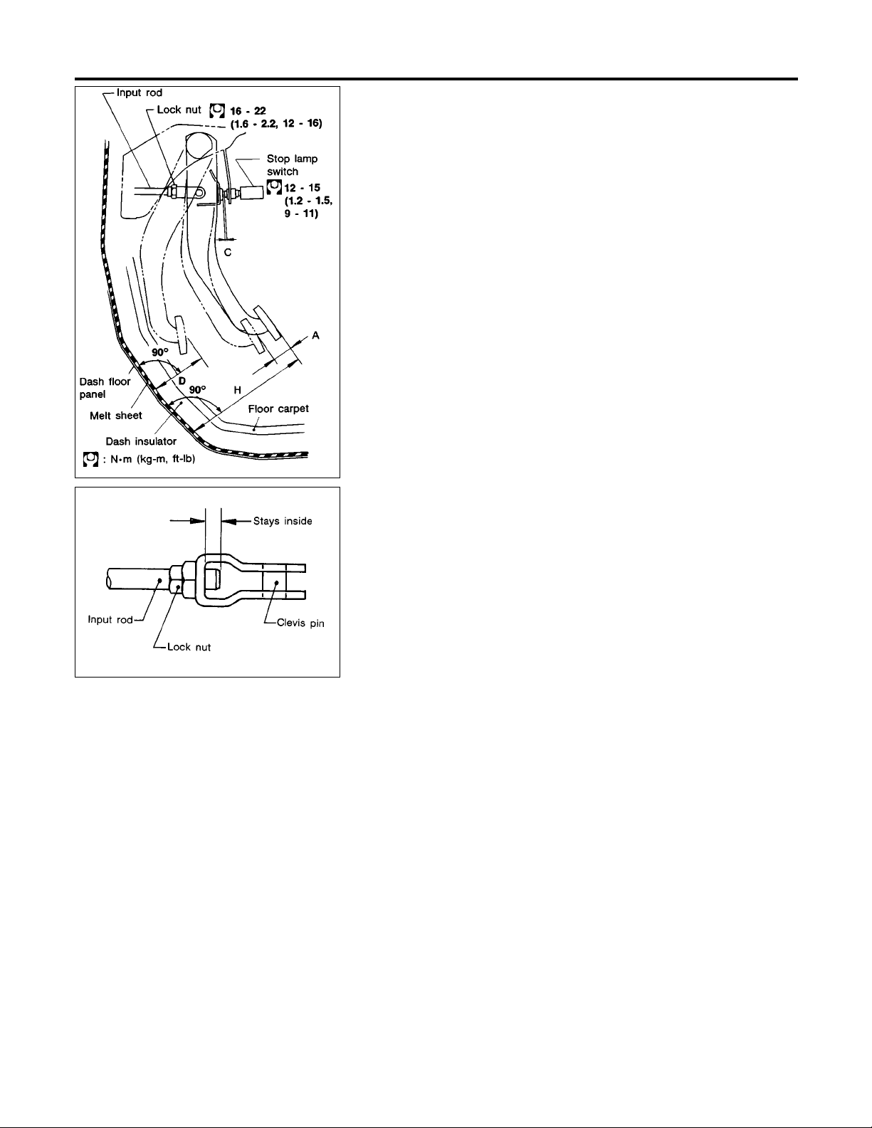
Check brake pedal free height from metal floor.
H: Free height
Refer to SDS (BR-73).
D: Depressed height
Refer to SDS (BR-73).
Under force of 490 N (50 kg, 110 lb) with engine run-
ning
,C2: Clearance between pedal stopper and
C
1
threaded end of stop lamp switch and ASCD switch
0.3 - 1.0 mm (0.012 - 0.039 in)
A: Pedal free play
1-3mm(0.04 - 0.12 in)
If necessary, adjust brake pedal free height.
1. Loosen lock nut and adjust pedal free height by turning brake
booster input rod. Then tighten lock nut.
Make sure that tip of input rod stays inside.
2. Adjust clearance “C
” and “C2” with stop lamp switch and
1
ASCD switch respectively. Then tighten lock nuts.
3. Check pedal free play.
Make sure that stop lamp is off when pedal is released.
4. Check brake pedal’s depressed height while engine is running.
If depressed height is below specified value, check brake sys-
tem for leaks, accumulation of air or any damage to compo-
nents (master cylinder, wheel cylinder, etc.). Then make nec-
essary repairs.
BR-12
Page 13
MASTER CYLINDER
Removal
Removal
CAUTION:
I Be careful not to splash brake fluid on painted areas; it
may cause paint damage. If brake fluid is splashed on
painted areas, wash it away with water immediately.
I In the case of brake fluid leakage from the master cylinder,
disassemble the cylinder. Then check piston cups for
deformation and scratches and replace necessary parts.
1. Connect a vinyl tube to air bleeder valve.
2. Drain brake fluid from each air bleeder valve, depressing brake
pedal to empty fluid from master cylinder.
3. Remove brake pipe flare nuts.
4. Remove master cylinder mounting nuts.
NGBR0019
GI
MA
EM
LC
EC
FE
CL
MT
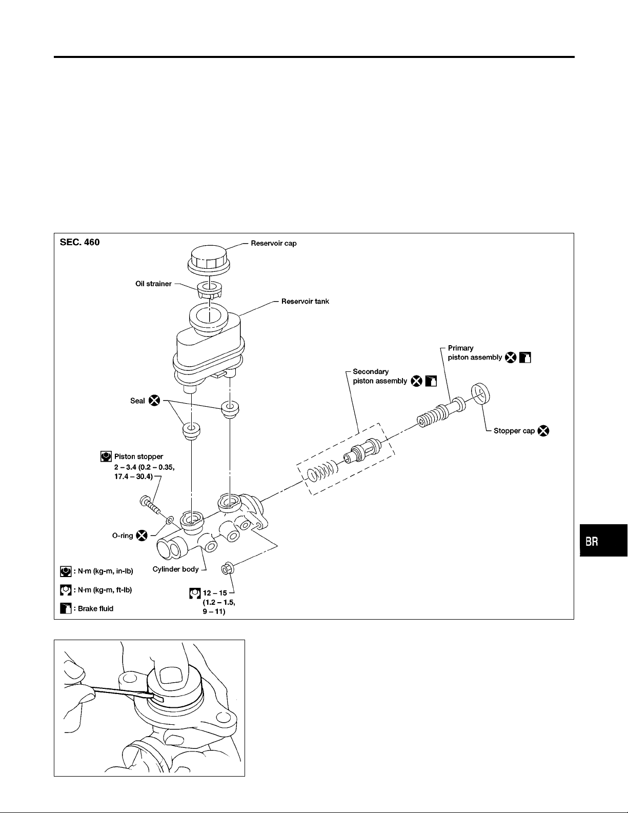
Disassembly
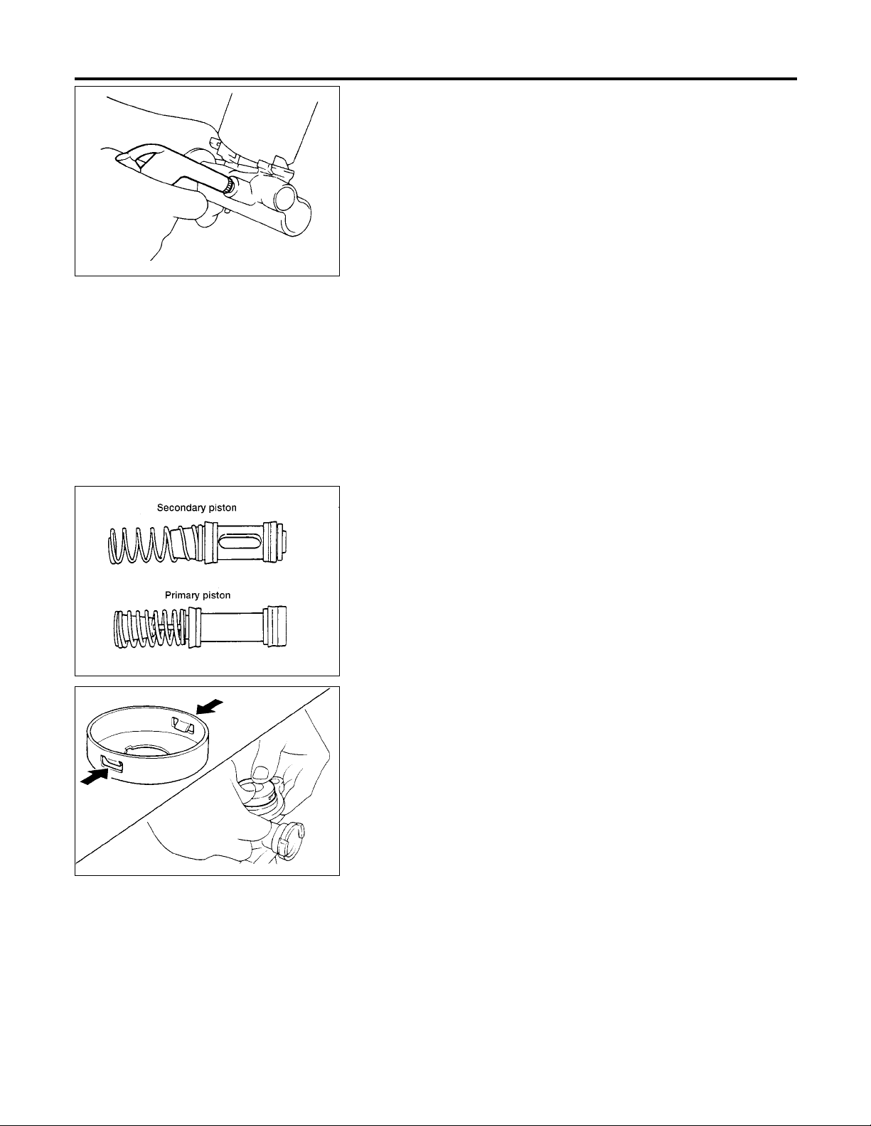
1. Bend claws of stopper cap outward.
ABR873
NGBR0020
AT
TF
PD
AX
SU
ST
RS
BT
SBR938A
HA
SC
EL
IDX
BR-13
Page 14
Disassembly (Cont’d)
MASTER CYLINDER
2. Remove piston stopper while piston is pushed into cylinder.
3. Remove piston assemblies.
If it is difficult to remove secondary piston assembly, gradually apply compressed air through fluid outlet.
4. Draw out reservoir tank.
SBR939A
ABR767
Inspection
NGBR0021
Check master cylinder inner wall for pin holes and scratches.
Replace if damaged.
Assembly
NGBR0022
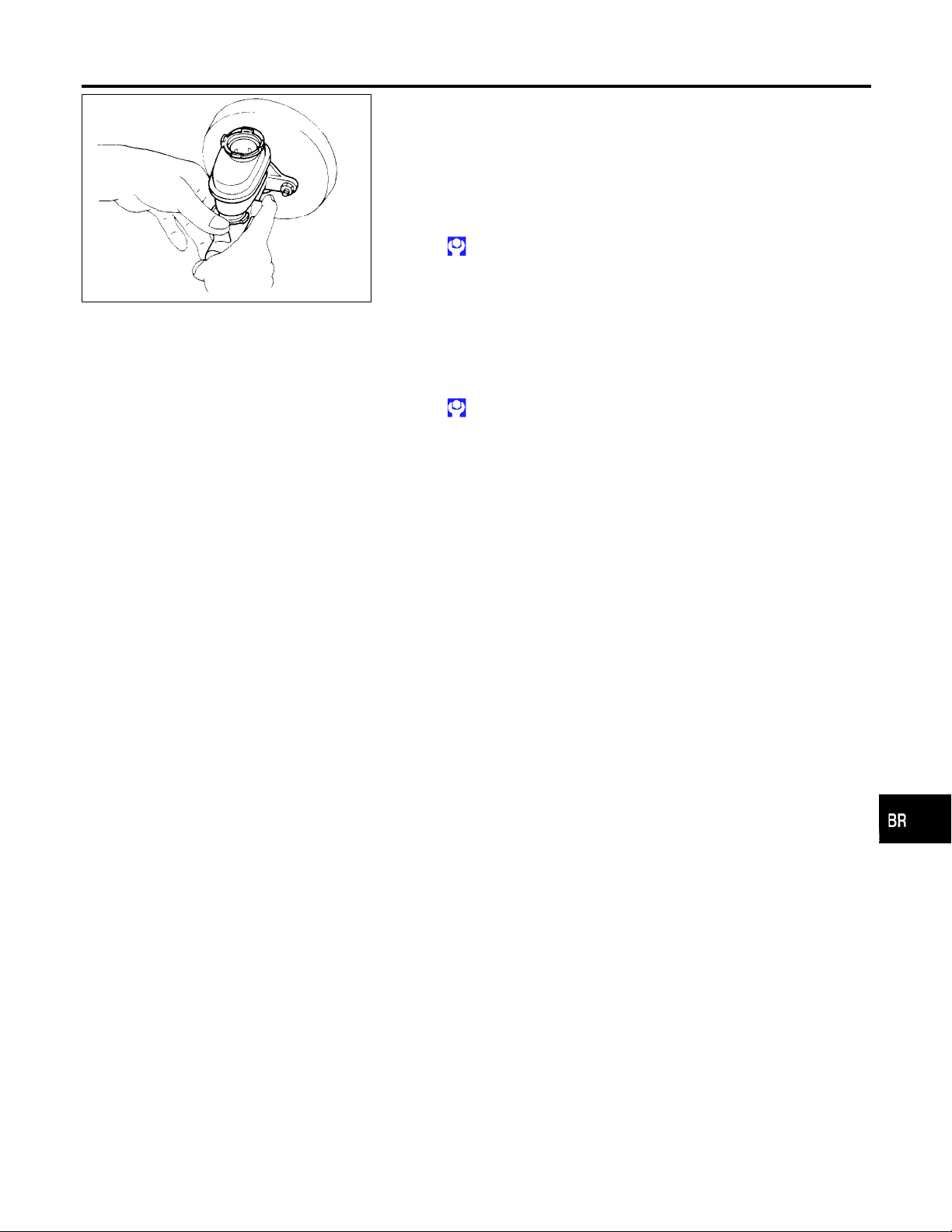
1. Insert secondary piston assembly. Then insert primary piston
assembly.
I Pay attention to direction of piston cups in figure at left.
Also, insert pistons squarely to avoid scratches on cylin-
der bore.
2. Install stopper cap.
Before installing stopper cap, ensure that claws are bent
inward.
3. Push reservoir tank seals into cylinder body.
4. Push reservoir tank into cylinder body.
SBR940A
BR-14
Page 15
MASTER CYLINDER
Installation
ABR190
Installation
CAUTION:
I Refill with new brake fluid “DOT 3”.
I Never reuse drained brake fluid.
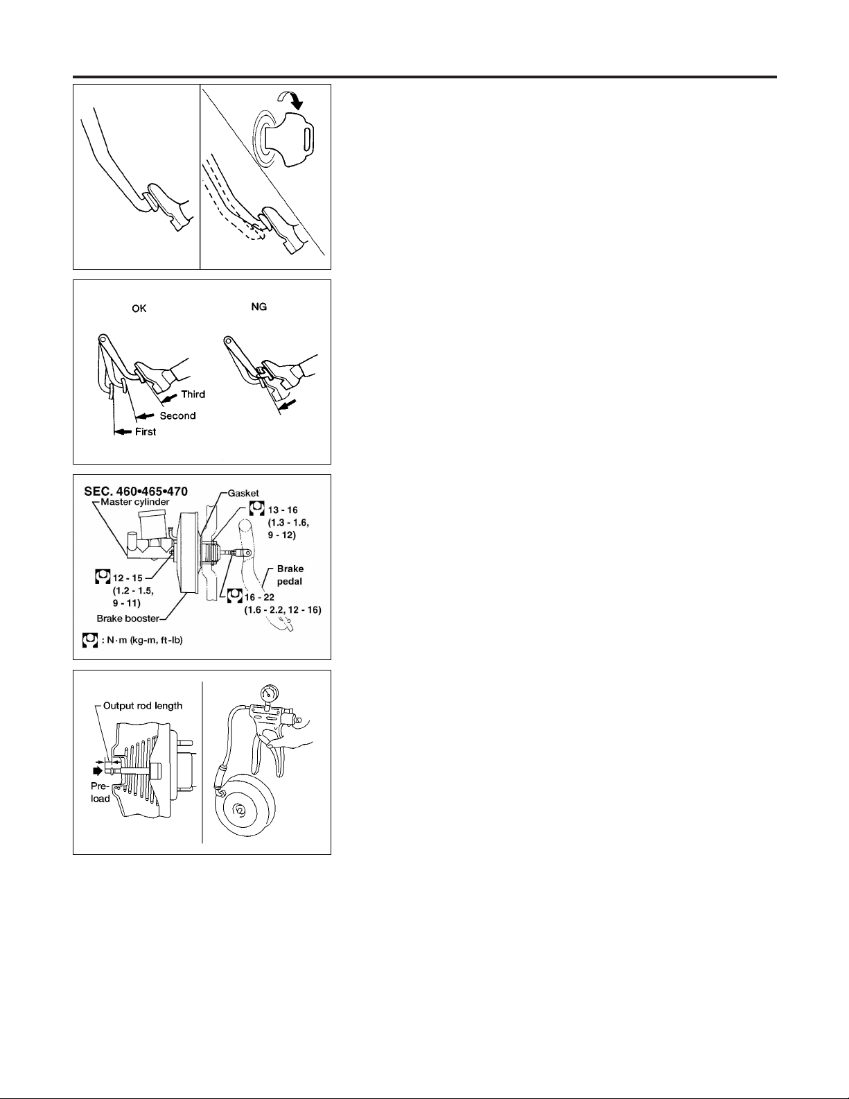
1. Place master cylinder onto brake booster and secure mount-
ing nuts lightly.
2. Torque mounting nuts.
: 12 - 15 N·m (1.2 - 1.5 kg-m,9-11ft-lb)
3. Fill up reservoir tank with new brake fluid.
4. Plug all ports on master cylinder with fingers to prevent air
suction while releasing brake pedal.
5. Have driver depress brake pedal slowly several times until no
air comes out of master cylinder.
6. Fit brake lines to master cylinder.
7. Tighten flare nuts.
: 15 - 17 N·m (1.5 - 1.8 kg-m, 11 - 13 ft-lb)
8. Bleed air. Refer to “Bleeding Brake System”, BR-8.
=NGBR0023
GI
MA
EM
LC
EC
FE
CL
MT
AT
TF
PD
AX
SU
ST
RS
BT
BR-15
HA
SC
EL
IDX
Page 16
On-vehicle Service
BRAKE BOOSTER
SBR002A
SBR365AA
On-vehicle Service
OPERATING CHECK
NGBR0024
NGBR0024S01
1. Depress brake pedal several times with engine off. After
exhausting vacuum, make sure there is no change in pedal
stroke.
2. Depress brake pedal, then start engine. If pedal goes down
slightly, operation is normal.
AIRTIGHT CHECK
NGBR0024S02
1. Start engine, and stop it after one or two minutes. Depress
brake pedal several times slowly. Booster is airtight if pedal
stroke is less each time.
2. Depress brake pedal while engine is running, and stop engine
with pedal depressed. The pedal stroke should not change
after holding pedal down for 30 seconds.
Removal
NGBR0025
CAUTION:
I Be careful not to splash brake fluid on painted areas; it
may cause paint damage. If brake fluid is splashed on
painted areas, wash it away with water immediately.
I Be careful not to deform or bend brake pipes, during
removal of booster.
ABR909
ABR908
Inspection
OUTPUT ROD LENGTH CHECK
NGBR0026
NGBR0026S01
1. Apply vacuum of −66.7 kPa (−500 mmHg, −19.69 inHg) to
brake booster with a hand vacuum pump.
2. Add preload of 19.6 N (2.0 kg, 4.4 lb) to output rod length.
3. Check output rod length.
Specified length:
10.275 - 10.525 mm (0.4045 - 0.4144 in)
BR-16
Page 17
BRAKE BOOSTER
Installation
SBR116BE
Installation
CAUTION:
I Be careful not to deform or bend brake pipes during instal-
lation of booster.
I Replace clevis pin if damaged.
I Refill with new brake fluid “DOT 3”.
I Never reuse drained brake fluid.
I Take care not to damage brake booster mounting bolt
thread when installing. Due to the narrow angle of
installation, the threads can be damaged by the dash
panel.
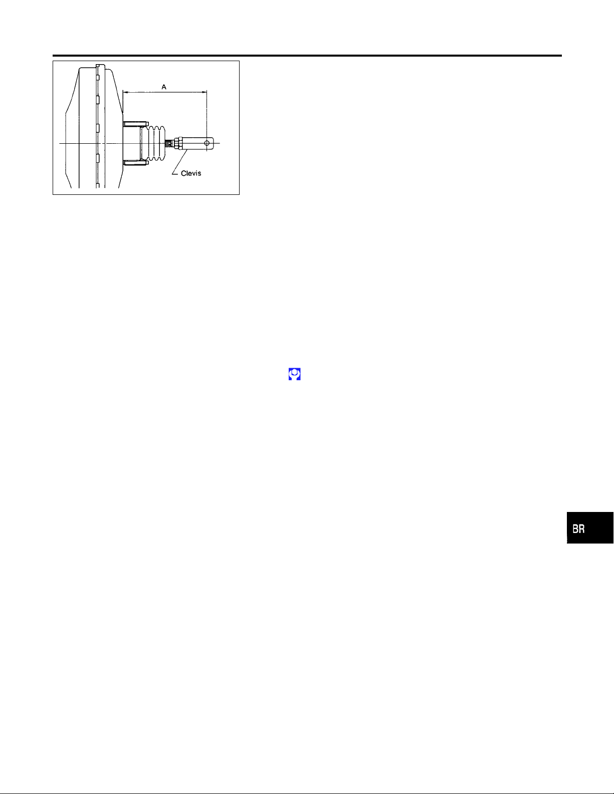
A: 138.5 mm (5.45 in)
1. Before fitting booster, temporarily adjust clevis to dimension
shown.
2. Fit booster, then secure mounting nuts (brake pedal bracket to
brake booster) lightly.
3. Connect brake pedal and booster input rod with clevis pin.
4. Secure mounting nuts.
Specification: 13 - 16 N·m (1.3 - 1.6 kg-m,9-12ft-lb)
5. Install master cylinder. Refer to “Installation” in “MASTER
CYLINDER”, BR-15.
6. Adjust brake pedal height and free play. Refer to “Adjustment”
in “BRAKE PEDAL AND BRACKET”, BR-12.
7. Secure lock nut for clevis.
: 16 - 22 N·m (1.6 - 2.2 kg-m, 12 - 16 ft-lb)
8. Bleed air. Refer to “Bleeding Brake System”, BR-8.
=NGBR0027
GI
MA
EM
LC
EC
FE
CL
MT
AT
TF
PD
AX
SU
ST
RS
BT
HA
SC
BR-17
EL
IDX
Page 18
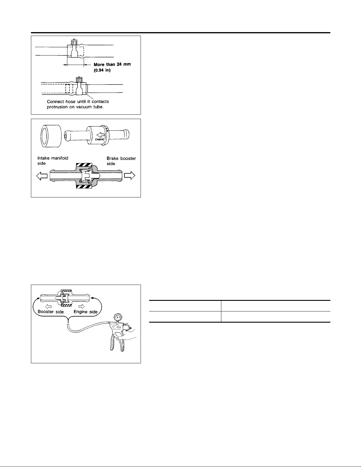
Removal and Installation
VACUUM PIPING
SBR225B
SBR498A
Removal and Installation
NGBR0029
CAUTION:
When installing vacuum hoses, pay attention to the following
points.
I Do not apply any oil or lubricants to vacuum hose and
check valve.
I Insert vacuum tube into vacuum hose as shown.
I Install check valve, paying attention to its direction.
Inspection
HOSES AND CONNECTORS
NGBR0030
NGBR0030S01
Check vacuum lines, connections and check valve for airtightness,
improper attachment chafing and deterioration.
SBR943A
CHECK VALVE
Check vacuum with a vacuum pump.
Connect to booster side Vacuum should exist.
Connect to engine side Vacuum should not exist.
BR-18
NGBR0030S02
Page 19
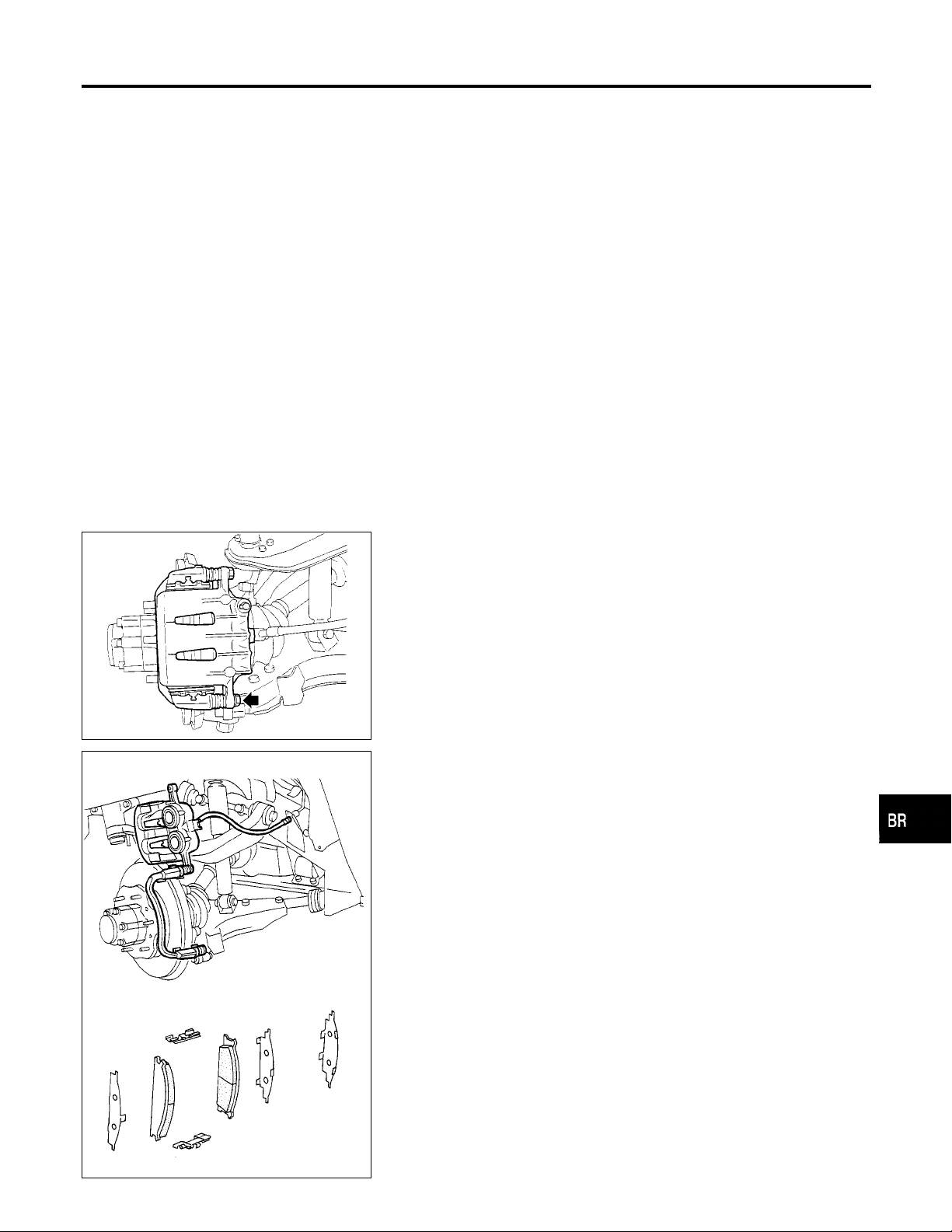
FRONT DISC BRAKE
Pad Replacement
Pad Replacement
WARNING:
Clean brakes with a vacuum dust collector to minimize the
hazard of airborne particles or other materials.
CAUTION:
I When cylinder body is open, do not depress brake pedal,
or piston will pop out.
I Be careful not to damage piston boot or get oil on rotor.
Always replace shims when replacing pads.
I If shims are rusted or show peeling of the rubber coat,
replace them with new shims.
I It is not necessary to remove connecting bolt except for
disassembly or replacement of caliper assembly. In this
case, suspend cylinder body with wire so as not to stretch
brake hose.
I Carefully monitor brake fluid level because brake fluid will
return to reservoir when pushing back piston.
1. Remove master cylinder reservoir cap.
2. Remove lower pin bolt.
NGBR0032
GI
MA
EM
LC
EC
FE
CL
MT
AT
SBR081A
3. Open cylinder body upward. Then remove pad retainers, and
inner and outer shims.
Standard pad thickness:
11 mm (0.43 in)
Pad wear limit:
2.0 mm (0.079 in)
Carefully monitor brake fluid level because brake fluid will
return to reservoir when pushing back piston.
TF
PD
AX
SU
ST
RS
BT
HA
SBR010B
SC
EL
IDX
BR-19
Page 20
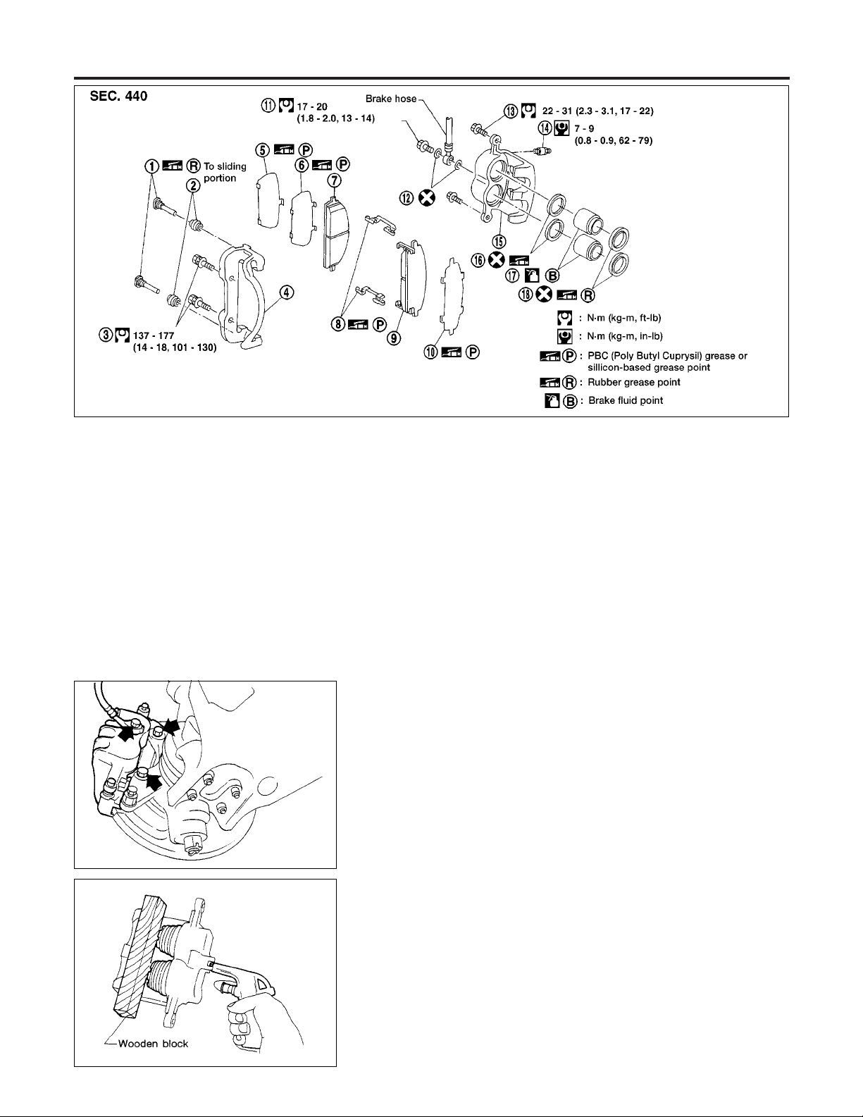
Pad Replacement (Cont’d)
FRONT DISC BRAKE
ABR918
SBR083A
Removal
NGBR0033
WARNING:
Clean brake pads with a vacuum dust collector to minimize the
hazard of airborne particles or other materials.
CAUTION:
Suspend caliper assembly with wire so as not to stretch brake
hose.
Remove torque member fixing bolts and connecting bolt.
It is not necessary to remove connecting bolt except for disassembly or replacement of caliper assembly. In this case,
suspend caliper assembly with wire so as not to stretch brake
hose.
Disassembly
NGBR0034
WARNING:
Do not place your fingers in front of piston.
CAUTION:
Do not scratch or score cylinder wall.
1. Push out piston with dust seal with compressed air.
2. Remove piston seal with a suitable tool.
SBR085A
BR-20
Page 21
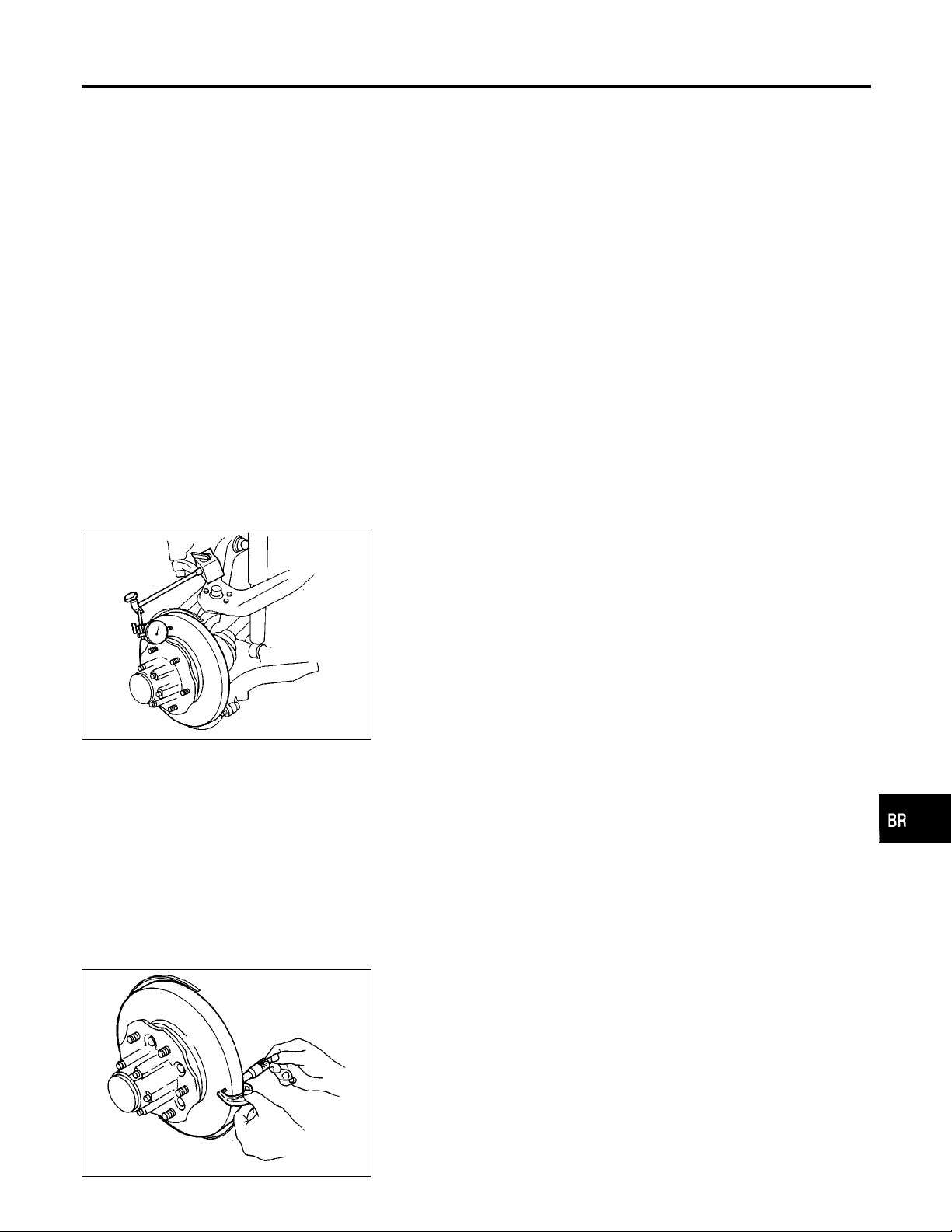
FRONT DISC BRAKE
Inspection
SBR089A
Inspection
CALIPER
Cylinder Body
I Check inside surface of cylinder for score, rust, wear, damage
and presence of foreign objects. If any of the above conditions
are observed, replace cylinder body.
I Minor damage from rust or foreign objects may be eliminated
by polishing surface with a fine emery paper. Replace cylinder
body if necessary.
CAUTION:
Use brake fluid to clean. Never use mineral oil.
Piston
CAUTION:
Piston sliding surface is plated. Do not polish with emery
paper even if rust or foreign objects are stuck to sliding surface.
Check pistons for uneven surface, chips or cracks. Replace if any
of these conditions are observed.
Slide Pin, Pin Bolt and Pin Boot
Check for wear, cracks, rust and other damage. Replace if any of
the above conditions are observed.
ROTOR
Runout
1. Check runout using a dial indicator.
Make sure that wheel bearing axial end play is within the
AX-4
specifications before measuring. Refer to
Bearing” in AX section. (“Front Wheel Bearing”,”ON VEHICLE
SERVICE”).
Maximum runout:
0.07 mm (0.0028 in)
2. If the runout is out of specification, machine rotor with on-car
brake lathe (“MAD, DL-8700”, “AMMCO 700 and 705” or
equivalent).
“Front Wheel
NGBR0035
NGBR0035S01
NGBR0035S0101
NGBR0035S0102
NGBR0035S0103
NGBR0035S02
NGBR0035S0201
GI
MA
EM
LC
EC
FE
CL
MT
AT
TF
PD
AX
SU
SBR090A
Thickness
Thickness variation (At least 8 positions):
Maximum 0.02 mm (0.0008 in)
If thickness variation exceeds the specification, turn rotor with oncar brake lathe.
Rotor repair limit:
26.0 mm (1.024 in)
NGBR0035S0202
BR-21
ST
RS
BT
HA
SC
EL
IDX
Page 22
Assembly
FRONT DISC BRAKE
SBR178C
SBR179CA
Assembly
NGBR0036
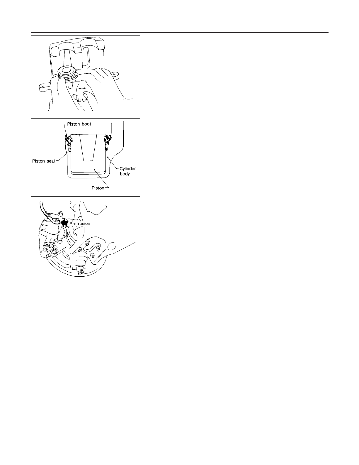
1. Insert piston seal into groove on cylinder body.
2. With piston boot fitted to piston, insert piston boot into groove
on cylinder body and install piston.
3. Properly secure piston boot
CAUTION:
I Secure dust seal property.
I Lubricate with new brake fluid before installing plastic pis-
tons into cylinder body.
Installation
NGBR0037
CAUTION:
I Refill with new brake fluid “DOT 3”.
I Never reuse drained brake fluid.
1. Install caliper assembly.
2. Install brake hose to caliper securely.
3. Install all parts and secure all bolts.
4. Bleed air. Refer to “Bleeding Brake System”, BR-8.
SBR084A
Brake Burnishing Procedure
NGBR0088
When experiencing soft brake pedal feel at very low mileage, or
after replacing the rotor, burnish the brake pad contact surfaces
according to the following procedures.
CAUTION:
Only perform this procedure under safe road and traffic conditions. Use extreme caution.
1. Drive the vehicle on a straight smooth road at 50 km/h (31
MPH).
2. Use medium brake pedal/foot effort to bring the vehicle to a
complete stop from 50 km/h (31 MPH). Adjust brake pedal/foot
pressure such that vehicle stopping time equals 3 to 5 sec-
onds.
3. To cool the brake system, drive the vehicle at 50 km/h (31
MPH) for 1 minute without stopping.
4. Repeat steps 1 to 3 10 times or more to complete the burnish-
ing procedure.
BR-22
Page 23
REAR DRUM BRAKE
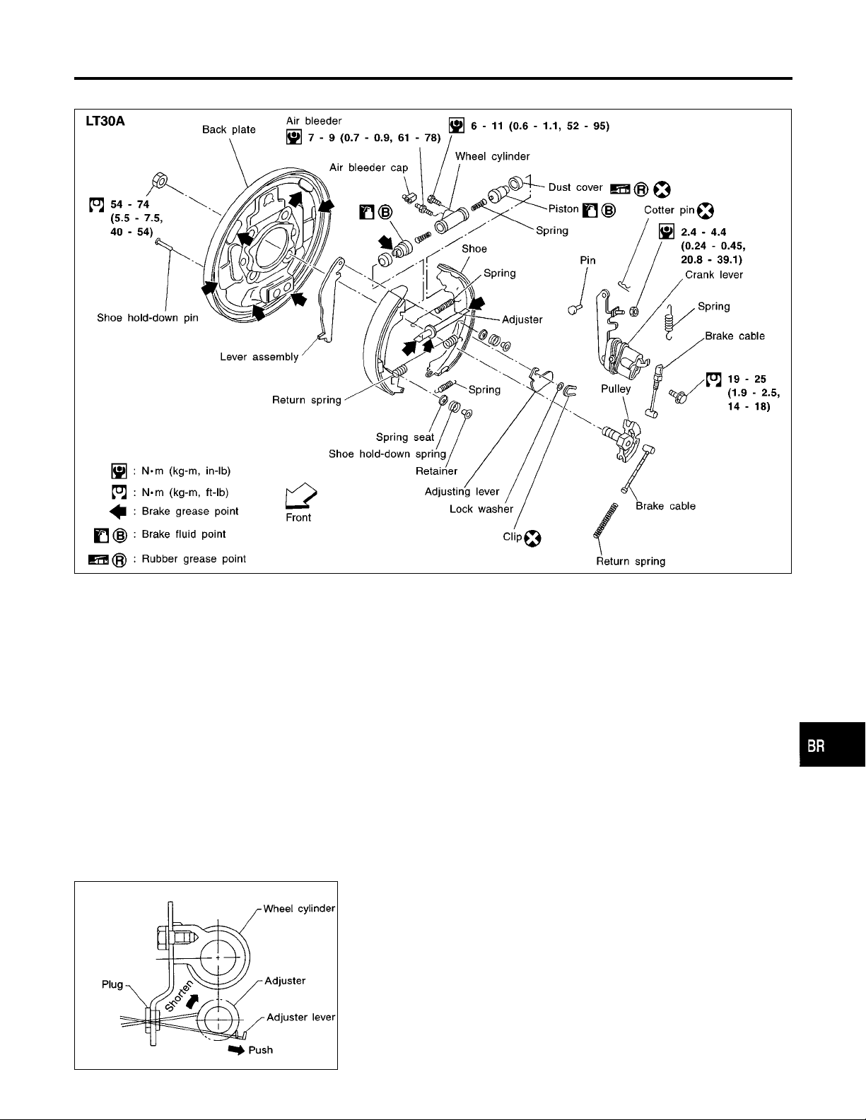
Components
Components
NGBR0038
GI
MA
EM
LC
EC
FE
CL
MT
ABR768
Removal
WARNING:
Clean brake lining with a vacuum dust collector to minimize
the hazard of airborne asbestos or other materials.
CAUTION:
Make sure parking brake lever is released completely.
1. Release parking brake lever fully, then remove drum.
I If drum is hard to remove, the following procedures
should be carried out.
a. Remove plug. Shorten adjuster to make clearance
between brake shoe and drum as shown
NGBR0039
AT
TF
PD
AX
SU
ST
RS
BT
HA
SBR264CA
SC
EL
IDX
BR-23
Page 24
Removal (Cont’d)
REAR DRUM BRAKE
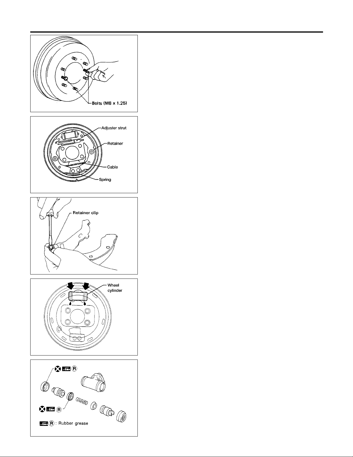
b. Install two bolts as shown. Tightenthe two bolts gradually.
SBR093A
2. After removing retainer, remove spring by rotating shoes.
Be careful not to damage wheel cylinder piston boots. Be
careful not to damage parking brake cable when separating it.
3. Remove adjuster.
4. Disconnect parking brake cable from toggle lever.
ABR369
ABR408
ABR370
5. Remove retainer ring with a suitable tool. Then separate toggle
lever and brake shoe.
Inspection
WHEEL CYLINDER
NGBR0040
NGBR0040S01
I Check wheel cylinder for leakage.
I Check for wear, damage and loose conditions.
Replace if any such condition exists.
SBR215B
Wheel Cylinder Overhaul
NGBR0041
I Check all internal parts for wear, rust and damage. Replace if
necessary.
I Pay attention so as not to scratch cylinder when installing pis-
tons.
BR-24
Page 25
REAR DRUM BRAKE
Inspection
SBR095A
SBR021A
ABR371
Inspection
DRUM
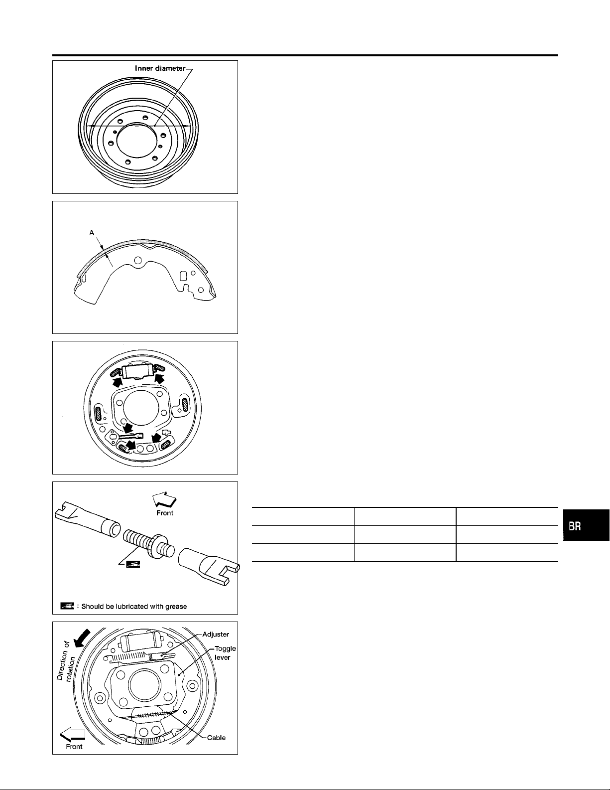
Maximum inner diameter (Repair limit):
LT30A 296.5 mm (11.67 in)
I Contact surface should be fine finished with No. 120 to 150
emery paper.
I Using a drum lathe, lathe brake drum if it shows scoring, par-
tial wear or stepped wear.
I After brake drum has been completely reconditioned or
replaced, check drum and shoes for proper contact pattern.
LINING
Check lining thickness.
Standard lining thickness:
LT30A 5.8 mm (0.228 in)
Lining wear limit (A):
LT30A 1.5 mm (0.059 in)
Installation
Always perform shoe clearance adjustment. Refer to BR-28.
I Burnish the brake contact surfaces after refinishing or
replacing drums or rotors, after replacing pads or linings,
or if a soft pedal occurs at very low mileage. Refer to
“Brake Burnishing Procedure”, “ON-VEHICLE SERVICE”,
BR-22
1. Fit toggle lever to brake shoe with retainer clip.
2. Apply brake grease to the contact areas shown at left.
3. Shorten adjuster by rotating it.
I Pay attention to direction of adjuster.
NGBR0042
NGBR0042S01
NGBR0042S02
NGBR0043
GI
MA
EM
LC
EC
FE
CL
MT
AT
TF
PD
AX
SU
ABR396
ABR372
Wheel Screw depression
Left Left-hand thread Yes
Right Right-hand thread No
4. Connect parking brake cable to toggle lever.
5. Install all parts.
Be careful not to damage wheel cylinder piston boots.
6. Check all parts are installed properly.
I After installations completed, adjust shoe-to-drum clear-
ance.
Pay attention to direction of adjuster assembly.
7. Install brake drum.
8. When installing new wheel cylinder or overhauling wheel
cylinder, bleed air. Refer to “Bleeding Brake System”, BR-8.
9. Adjust parking brake. Refer to “Adjustment”, “PARKING
BRAKE CONTROL”, BR-28.
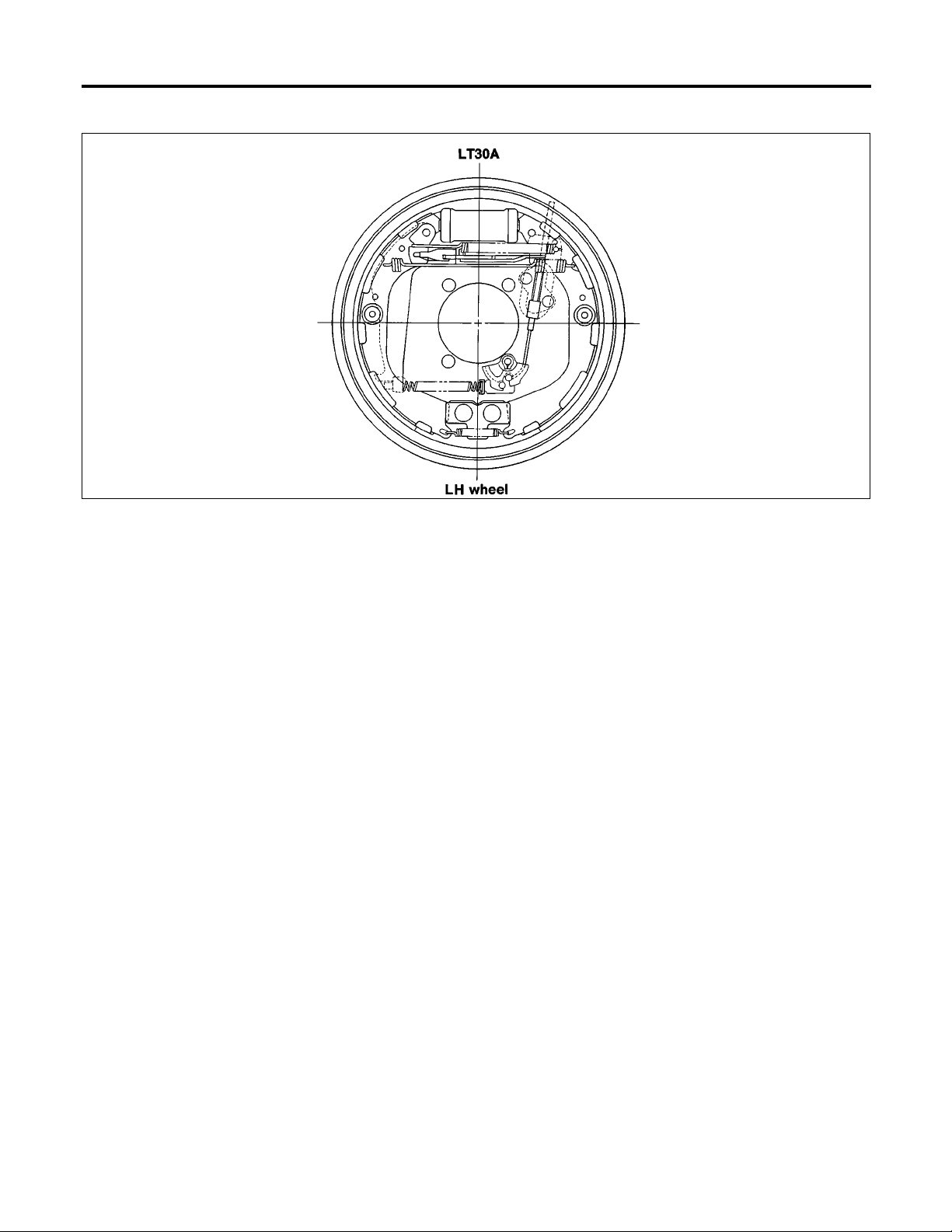
I Install all the parts by referring to to the figure below.
I After installing crank lever on back plate, make sure that there
BR-25
ST
RS
BT
HA
SC
EL
IDX
Page 26
Installation (Cont’d)
REAR DRUM BRAKE
is no play between crank lever and back plate. If play exists,
adjust bolt A and lock nut B.
ABR827
BR-26
Page 27
PARKING BRAKE CONTROL
Components
Components
NGBR0044
GI
MA
EM
LC
EC
FE
CL
MT
ABR874
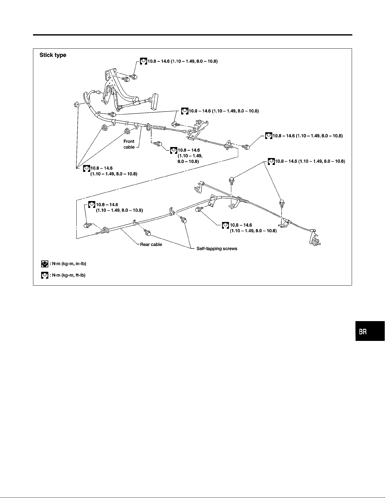
Removal and Installation
I Be careful not to damage cable.
I Make sure there is no free play after installation.
Inspection
1. Check control lever for wear and other damage. Replace if
necessary.
2. Check wires for discontinuity and deterioration. Replace if necessary.
3. Check warning lamp and switch. Replace if necessary.
4. Check part at each connecting portion and, if found deformed
or damaged, replace.
NGBR0045
NGBR0046
AT
TF
PD
AX
SU
ST
RS
BT
HA
SC
EL
BR-27
IDX
Page 28
Adjustment
PARKING BRAKE CONTROL
ABR771
ABR405
Adjustment
NGBR0047
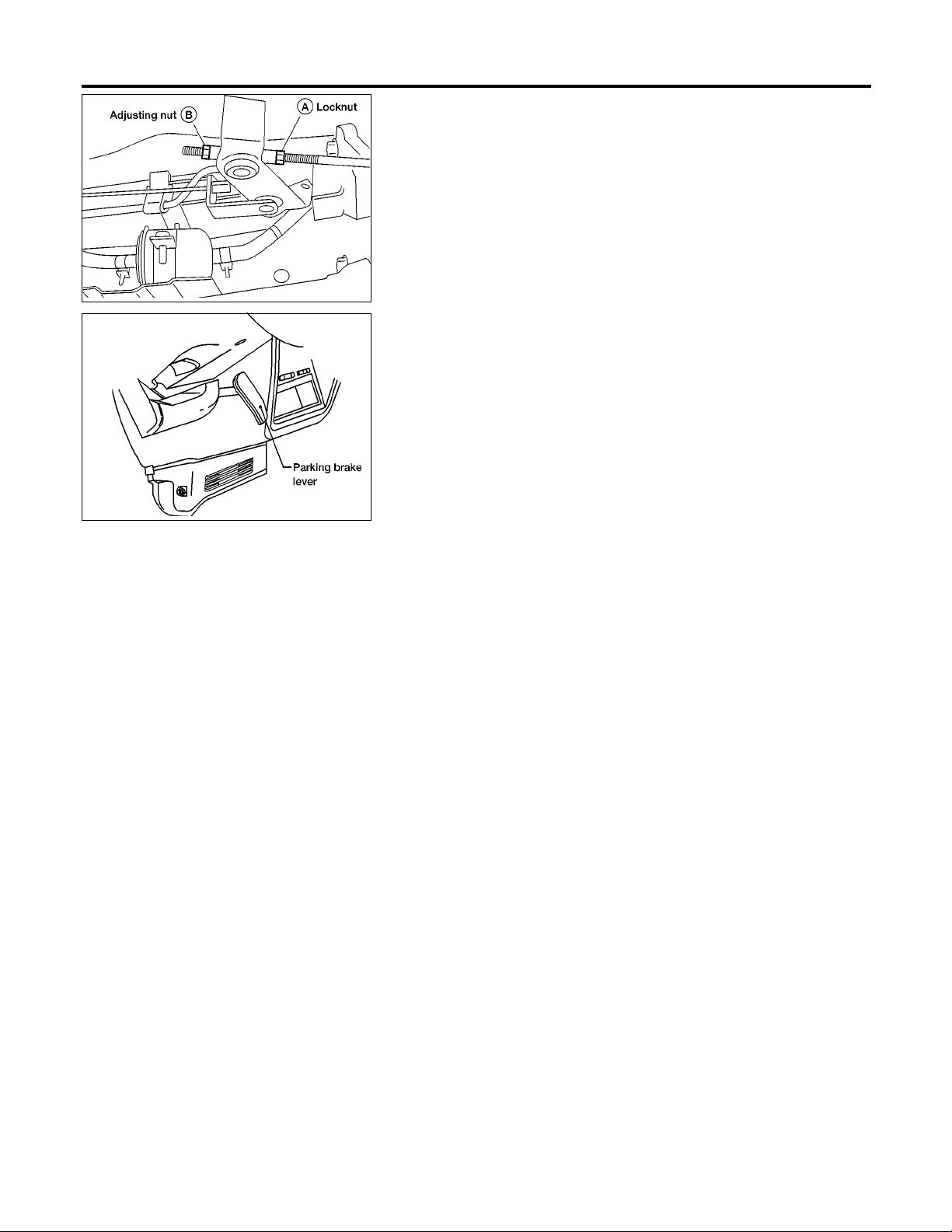
Adjust parking brake as follows:
1. Fully release parking brake lever.
2. Loosen A and rotate B until parking brake cable loosens.
3. Depress brake pedal several times until clicking sound does
not occur from rear brakes.
4. Adjust clearance between rear brake shoe and drum.
5. Adjust parking lever stroke by rotating B.
6. Pull parking brake lever with specified force. Check lever
stroke and ensure smooth operation.
7. Readjust clearance between rear brake shoe and drum.
BR-28
Page 29
DESCRIPTION
ABS
Purpose
Purpose
The Anti-Lock Brake System (ABS) consists of electronic and hydraulic components. It allows for control of
braking force so locking of the wheels can be avoided.
1) Improves proper tracking performance through steering wheel operation.
2) Eases obstacle avoidance through steering wheel operation.
3) Improves vehicle stability.
Operation
I When the vehicle speed is less than 10 km/h (6 MPH) this system does not work.
I The Anti-Lock Brake System (ABS) has a self-test function. The system turns on the ABS warning lamp
for 1 second each time the ignition switch is turned ON. After the engine is started, the ABS warning lamp
turns off. The system performs a test the first time the vehicle reaches 6 km/h (4 MPH).Amechanical noise
may be heard as the ABS performs this self-test. This is a normal part of the self-test feature. If a malfunction is found during this check, the ABS warning lamp will stay on.
I While driving, a mechanical noise may be heard during ABS operation. This is a normal condition.
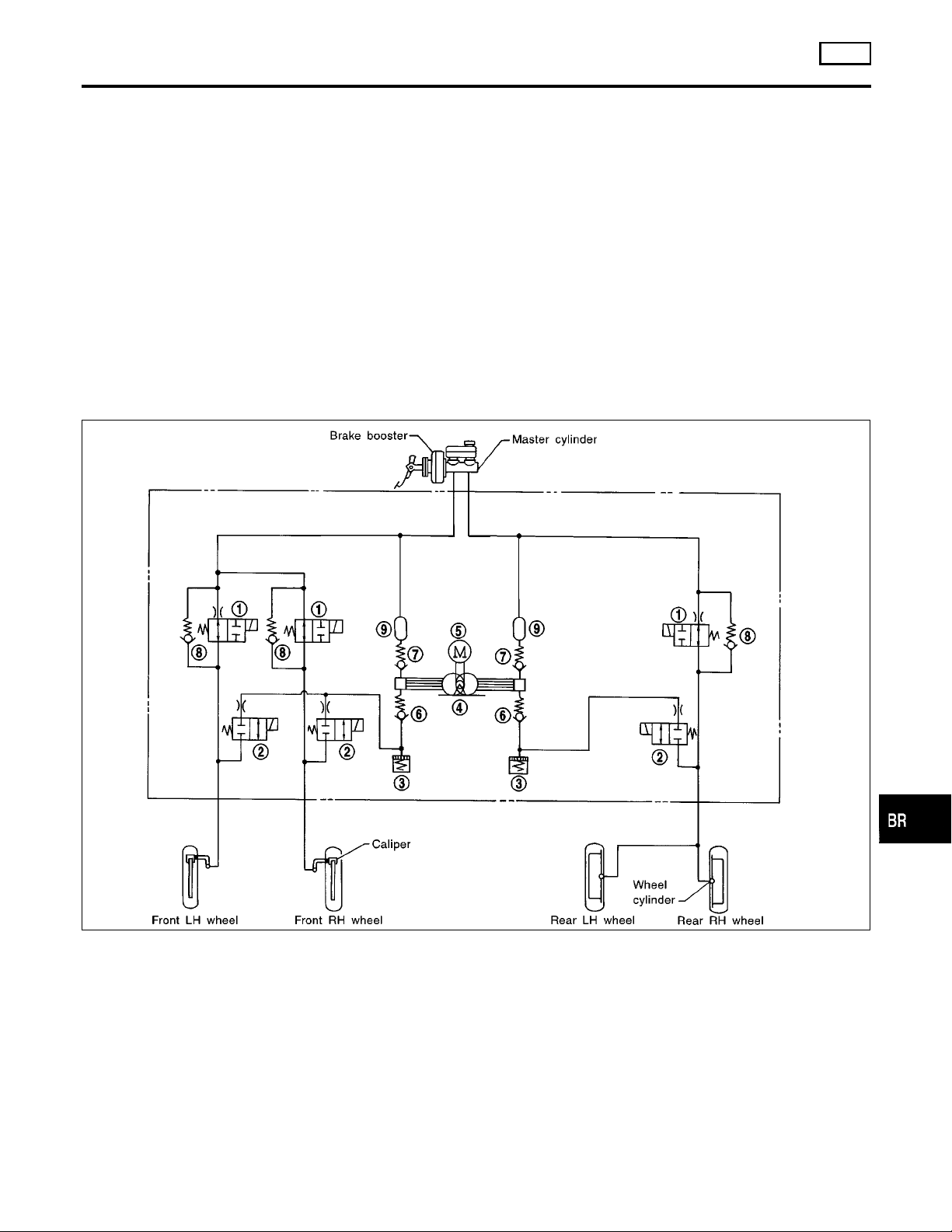
ABS Hydraulic Circuit
NGBR0089
NGBR0090
NGBR0091
GI
MA
EM
LC
EC
FE
CL
MT
1. Inlet solenoid valve
2. Outlet solenoid valve
3. Pump
4. Motor
5. Bypass check valve
SBR859D
6. Damper
7. Solenoid valve relay actuator
AT
TF
PD
AX
SU
ST
RS
BT
BR-29
HA
SC
EL
IDX
Page 30
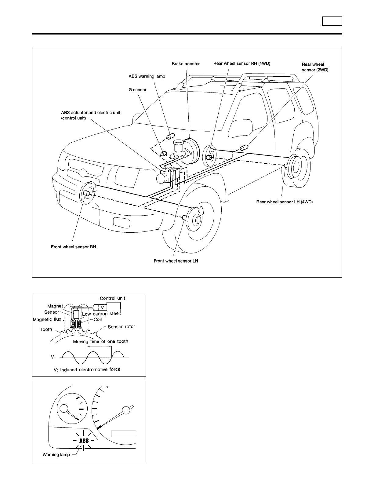
System Components
DESCRIPTION
ABS
System Components
NGBR0092
SBR124B
ABR910
ABR857
System Description
WHEEL SENSOR
NGBR0093
NGBR0093S01
The sensor units consist of a gear-shaped sensor rotor and a sensor element. The element contains a bar magnet around which a
coil is wound. The front sensors are installed on the back of the
front brake rotors. For 2-wheel drive systems a single sensor is
installed at the companion flange of the rear axle housing and for
4-wheel drive systemsthere is asensor installed ateach rear brake
drum. As the wheel rotates, the sensor generates a sine-wave
pattern. The frequency and voltage increase(s) as the rotating
speed increases.
CONTROL UNIT (BUILT-IN ABS ACTUATOR AND ELECTRIC UNIT)
The control unit computes the wheel rotating speed by the signal
current sent from the sensor. Then it supplies a DC current to the
actuator solenoid valve. It also controls ON-OFF operation of the
valve relay and motor relay. If any electrical malfunction should be
detected in the system, the control unit causes the warning lamp
to light up. In this condition, the ABS will be deactivated by the
control unit, and the vehicle’s brake system reverts to normal
operation. (For control unit layout, refer to ABS ACTUATOR AND
ELECTRIC UNIT, BR-31.)
NGBR0093S02
BR-30
Page 31
DESCRIPTION
ABS
System Description (Cont’d)
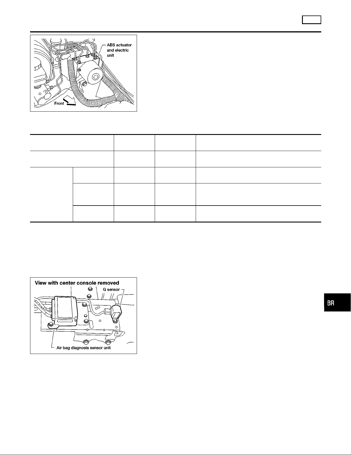
ABS ACTUATOR AND ELECTRIC UNIT
The ABS actuator and electric unit contains:
I An electric motor and pump
I Two relays
I Six solenoid valves, each inlet and outlet for
— LH front
— RH front
— Rear
I ABS control unit
ABR858
This component controls the hydraulic circuit and increases, holds
or decreases hydraulic pressure to all or individual wheels. The
ABS actuator and electric unit is serviced as an assembly.
ABS Actuator Operation
Inlet solenoid
valve
Normal brake operation OFF (Open) OFF (Closed)
Pressure hold ON (Closed) OFF (Closed)
ABS operation
Pressure
decrease
Pressure
increase
ON (Closed) ON (Open)
OFF (Open) OFF (Closed)
Outlet solenoid
valve
G SENSOR (4WD MODELS)
The G sensor senses deceleration during braking to determine
whether the vehicle is being driven on a high µ road (asphalt road,
etc.) or a low µ road (snow-covered road, etc.). It then sends a
signal to the ABS control unit.
NGBR0093S03
NGBR0093S0301
Master cylinder brake fluid pressure is directly transmitted to caliper via the inlet solenoid valve.
Hydraulic circuit is shut off to hold the caliper brake
fluid pressure.
Caliper brake fluid is sent to reservoir via the outlet
solenoid valve. Then it is pushed up to the master cylinder by pump.
Master cylinder brake fluid pressure is transmitted to
caliper.
NGBR0093S05
GI
MA
EM
LC
EC
FE
CL
MT
AT
TF
PD
AX
ABR859
This signal is recieved by the ABS control unit as a variable voltage signal. The input voltage varies from 1.3V ±0.125V during a
hard deceleration condition, to 2.5V ±0.125V with the vehicle
stopped and to 3.7V ±0.125Vduring a hard deceleration in reverse.
BR-31
SU
ST
RS
BT
HA
SC
EL
IDX
Page 32
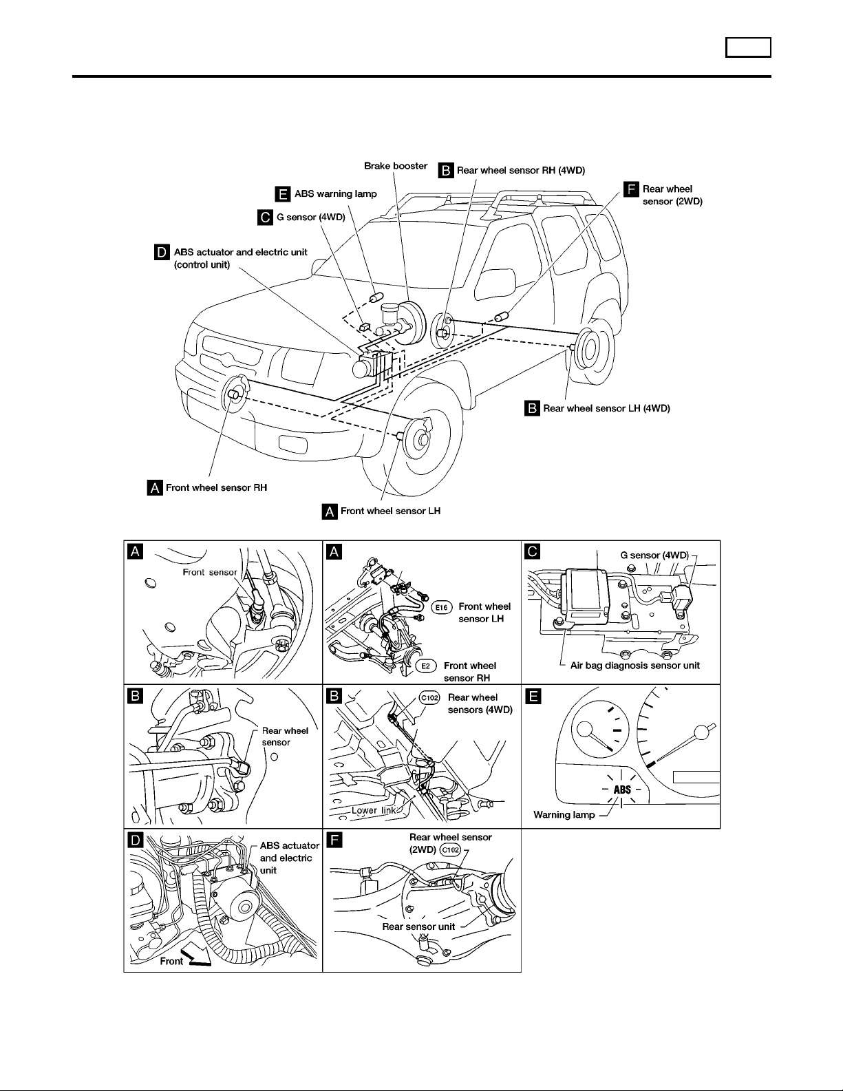
Component Parts and Harness Connector Location
DESCRIPTION
Component Parts and Harness Connector
Location
ABS
NGBR0094
BR-32
ABR860
Page 33
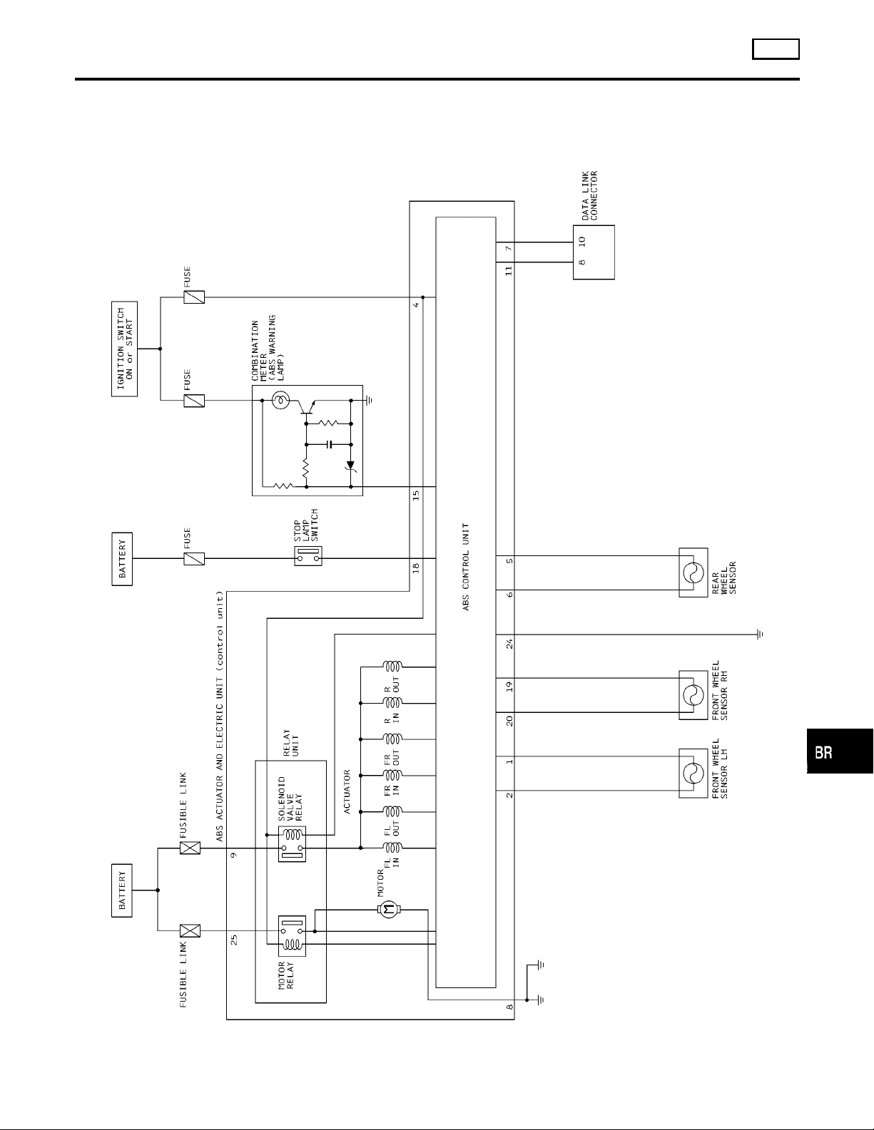
DESCRIPTION
ABS
Schematic
Schematic
2–WHEEL DRIVE
NGBR0095
NGBR0095S01
GI
MA
EM
LC
EC
FE
CL
MT
AT
TF
PD
AX
SU
ST
RS
BT
BR-33
HA
SC
EL
ABR816
IDX
Page 34

Schematic (Cont’d)
DESCRIPTION
ABS
4–WHEEL DRIVE
NGBR0095S02
BR-34
ABR820
Page 35
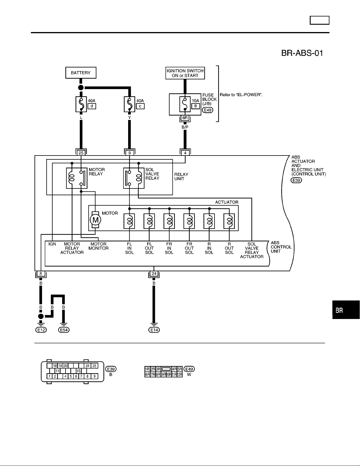
DESCRIPTION
ABS
Wiring Diagram — ABS — 2WD —
Wiring Diagram — ABS — 2WD —
NGBR0096
GI
MA
EM
LC
EC
FE
CL
MT
AT
TF
PD
AX
SU
ST
RS
BT
BR-35
ABR817
HA
SC
EL
IDX
Page 36
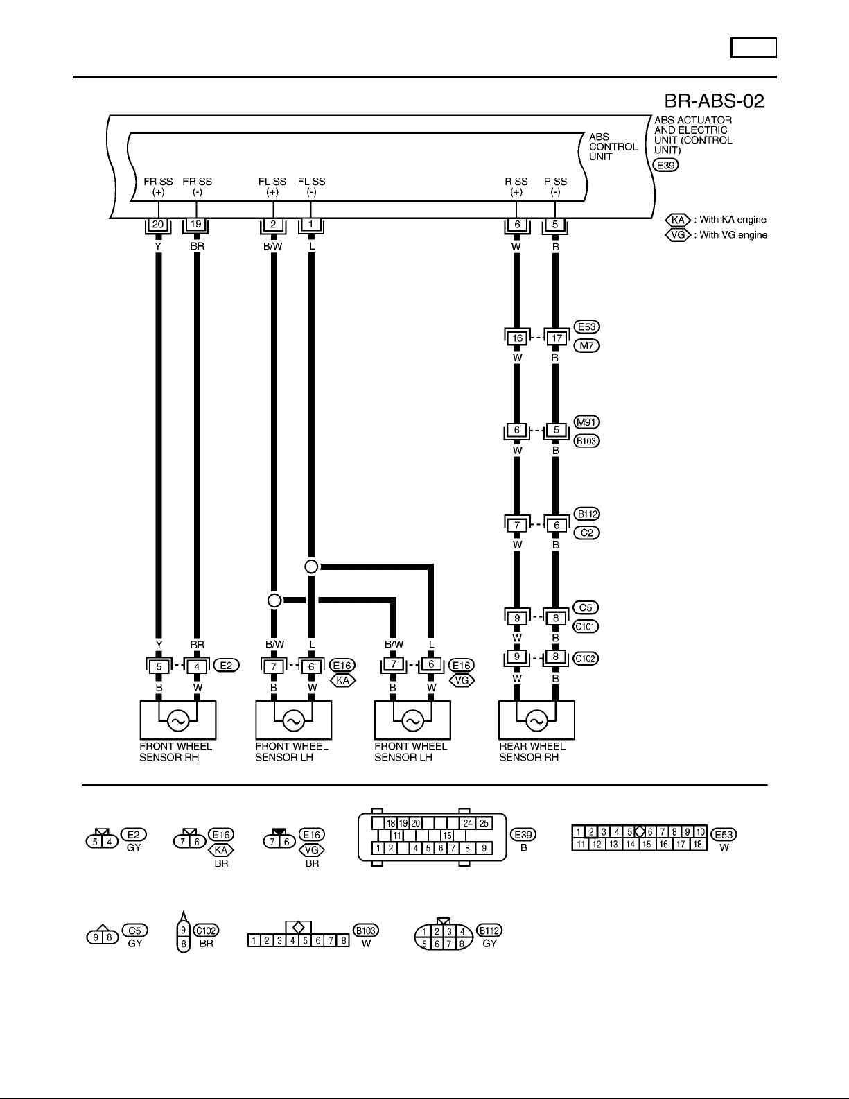
Wiring Diagram — ABS — 2WD — (Cont’d)
DESCRIPTION
ABS
BR-36
ABR818
Page 37
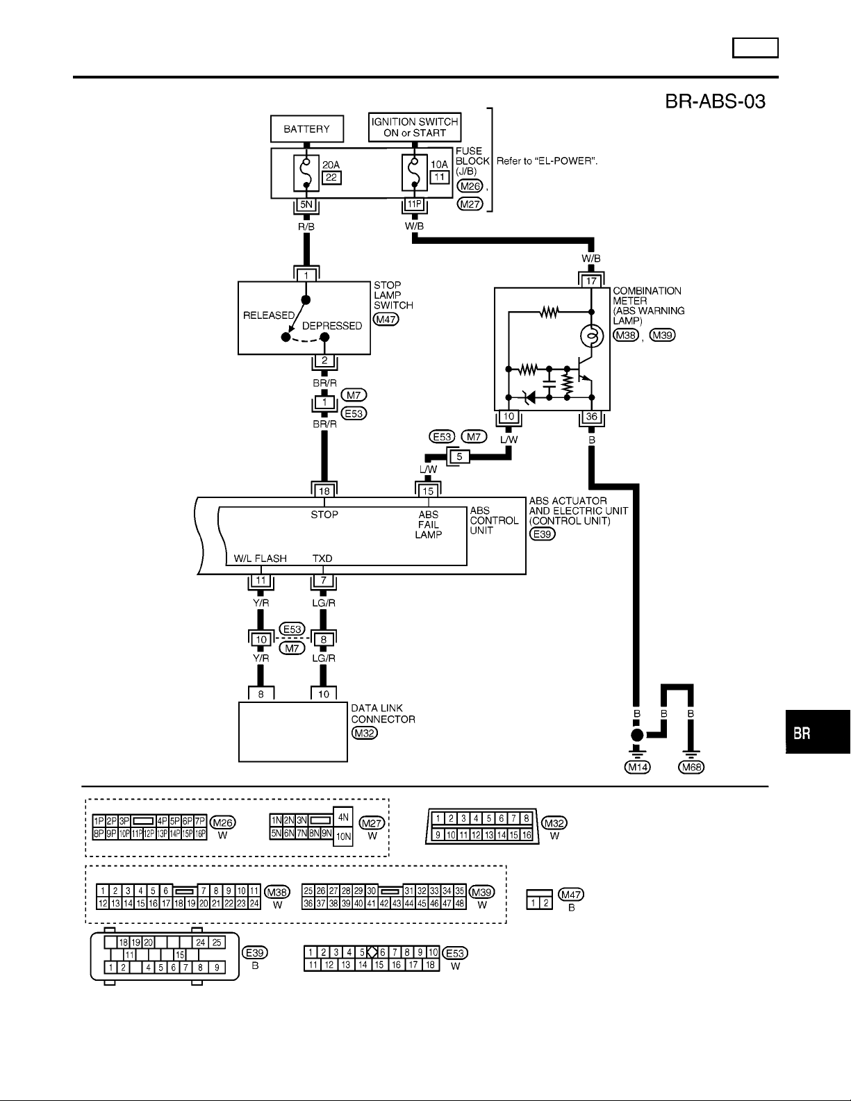
DESCRIPTION
ABS
Wiring Diagram — ABS — 2WD — (Cont’d)
GI
MA
EM
LC
EC
FE
CL
MT
AT
TF
PD
AX
SU
ST
RS
BR-37
BT
HA
SC
ABR819
EL
IDX
Page 38
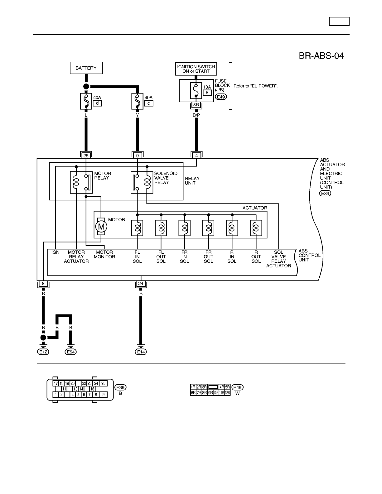
Wiring Diagram — ABS — 4WD —
DESCRIPTION
ABS
Wiring Diagram — ABS — 4WD —
NGBR0122
BR-38
ABR821
Page 39
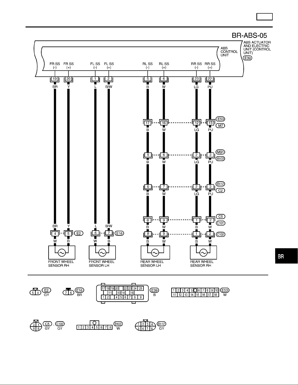
DESCRIPTION
ABS
Wiring Diagram — ABS — 4WD — (Cont’d)
GI
MA
EM
LC
EC
FE
CL
MT
AT
TF
PD
AX
SU
ST
RS
BR-39
BT
HA
SC
ABR822
EL
IDX
Page 40
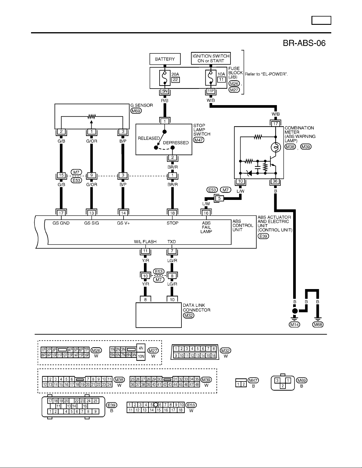
Wiring Diagram — ABS — 4WD — (Cont’d)
DESCRIPTION
ABS
BR-40
ABR823
Page 41
ON BOARD DIAGNOSTIC SYSTEM DESCRIPTION
ABS
Self-diagnosis
Self-diagnosis
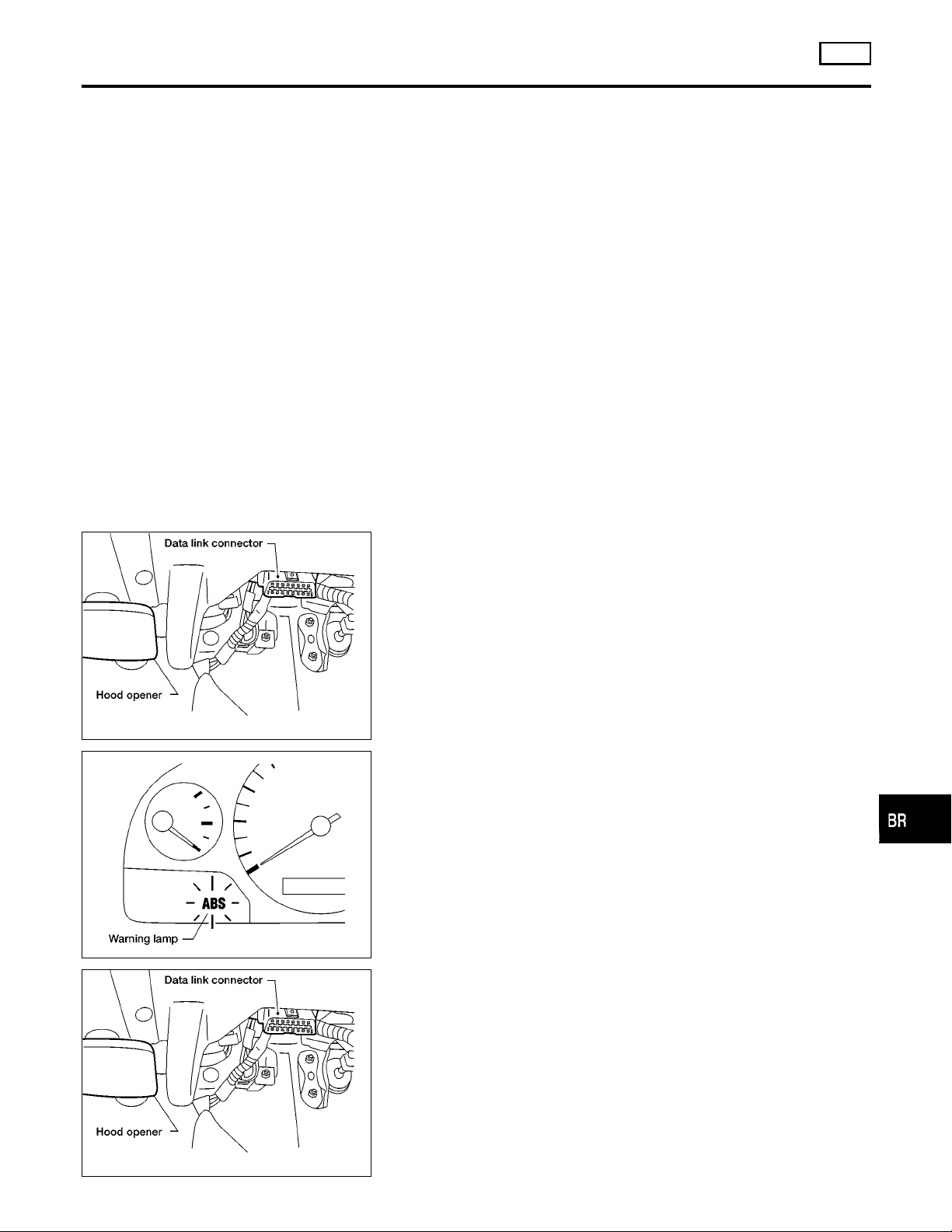
FUNCTION
I When a problem occurs in the ABS, the warning lamp on the
instrument panel comes on. [To start the self-diagnostic results
mode, ground the self-diagnostic (check) terminal 8 located on
the “Data link connector”. The location of the malfunction is
indicated by the warning lamp flashing]
SELF-DIAGNOSIS PROCEDURE
NOTE:
CONSULT-II is not applicable to ABS.
Use on board diagnostic system with ABS warning lamp.
1. Drive vehicle over 30 km/h (19 MPH) for at least one minute.
2. Turn ignition switch OFF.
3. Ground terminal 8 of “Data link connector for CONSULT-II” with
a suitable harness.
4. Turn ignition switch ON while grounding terminal 8.
Do not depress brake pedal.
NGBR0097
NGBR0097S01
NGBR0097S02
GI
MA
EM
LC
EC
FE
CL
MT
AT
TF
ABR847
ABR910
ABR847
5. After 3.0 seconds, the warning lamp starts flashing to indicate
the malfunction code No. (See NOTE.)
6. Verify the location of the malfunction with the malfunction code
chart. Refer to BR-48. Then make the necessary repairs following the diagnostic procedures.
7. After the malfunctions are repaired, erase the malfunction
codes stored in the control unit. Refer to BR-42.
8. Rerun the self-diagnostic results mode to verify that the malfunction codes have been erased.
9. Disconnect the check terminal from the ground. The self-diagnostic results mode is now complete.
10. Check warning lamp for deactivation after driving vehicle over
30 km/h (19 MPH) for at least one minute.
11. After making certain that warning lamp does not come on, test
the ABS in a safe area to verify that it functions properly.
NOTE:
The indication terminates after 5 minutes.
However, when the ignition switch is turned from OFF to ON, the
indication starts flashing again.
BR-41
PD
AX
SU
ST
RS
BT
HA
SC
EL
IDX
Page 42
Self-diagnosis (Cont’d)
ON BOARD DIAGNOSTIC SYSTEM DESCRIPTION
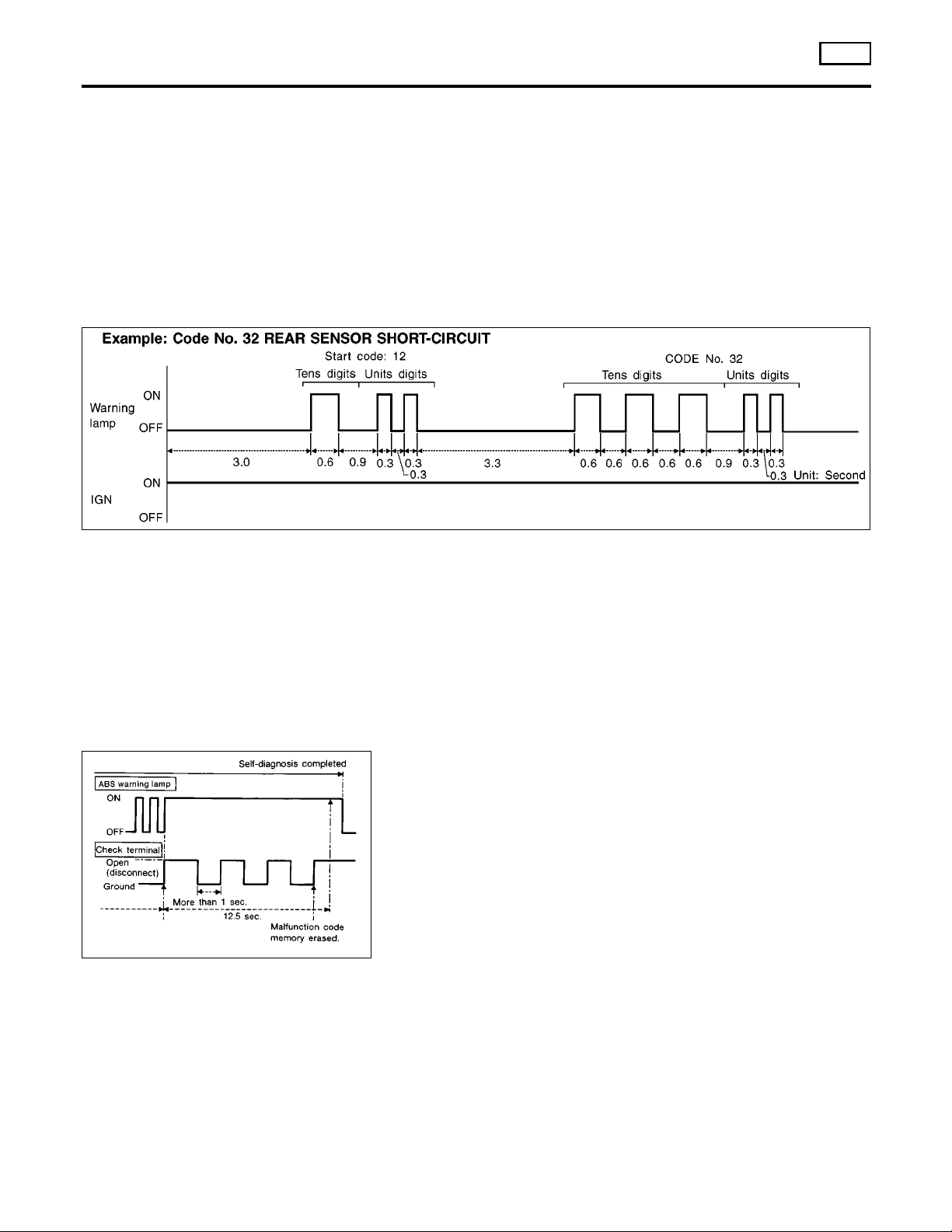
HOW TO READ SELF-DIAGNOSTIC RESULTS (MALFUNCTION CODES)
1. Determine the code No. by counting the number of times the
warning lamp flashes on and off.
2. When several malfunctions occur at one time, up to three code
numbers can be stored; the latest malfunction will be indicated
first.
3. The indication begins with the start code 12. After that a maximum of three code numbers appear in the order of the lowesr
to highest. The indication then returns to the start code 12 to
repeat (the indication will stay on for five minutes at the most).
4. The malfunction code chart is given on page BR-48.
ABS
=NGBR0097S03
ABR256
SBR457D
HOW TO ERASE SELF-DIAGNOSTIC RESULTS (MALFUNCTION CODES)
1. Disconnect the check terminal from ground (ABS warning lamp
will stay lit).
2. Within 12.5 seconds, ground the check terminal three times.
Each terminal ground must last more than 1 second. The ABS
warning lamp goes out after the erase operation has been
completed.
3. Perform self-diagnosis again. Refer to BR-41. Only the startcode should appear, no malfunction codes.
NGBR0097S04
BR-42
Page 43
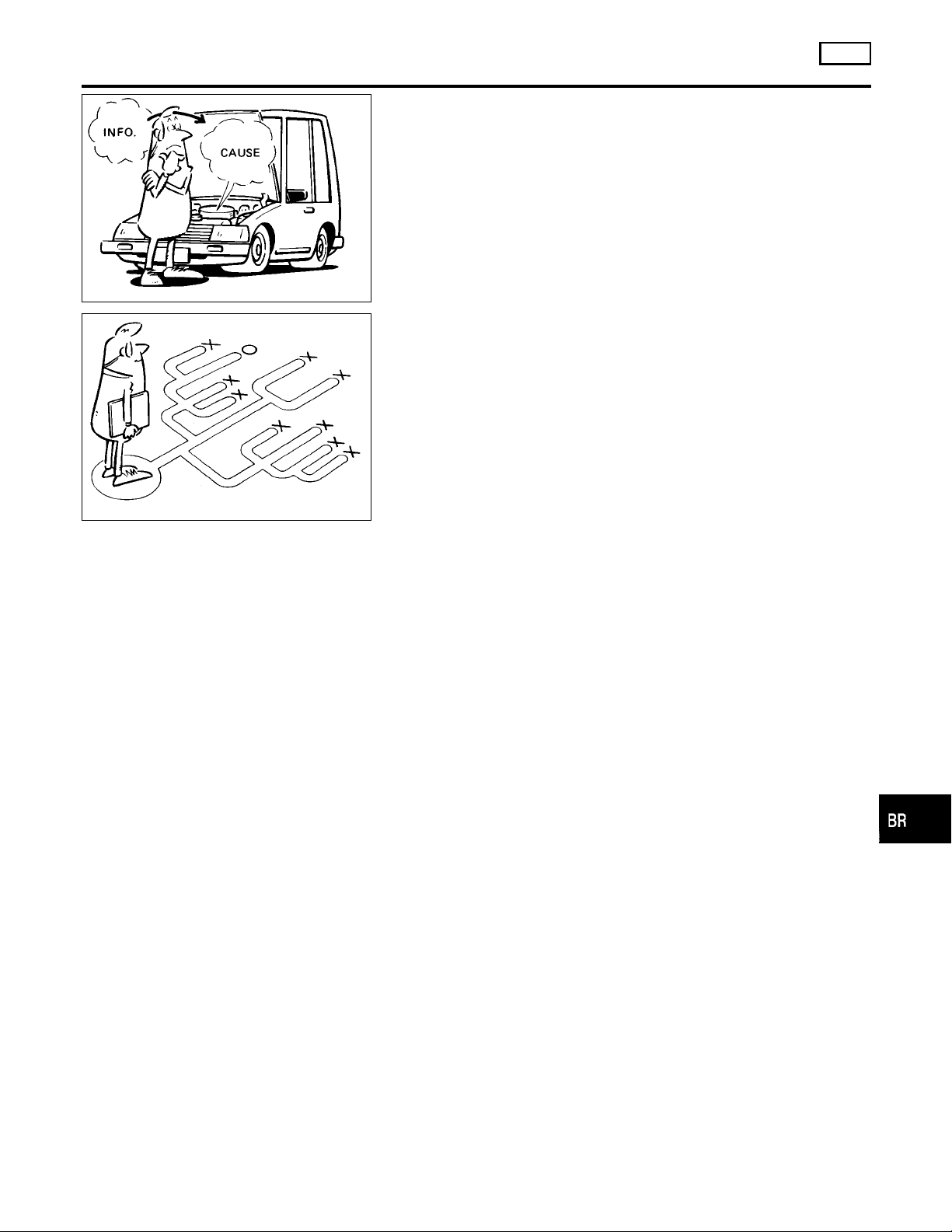
TROUBLE DIAGNOSIS — INTRODUCTION
How to Perform Trouble Diagnoses for Quick and Accurate Repair
How to Perform Trouble Diagnoses for Quick
and Accurate Repair
INTRODUCTION
The ABS system has an electronic control unit to control major
functions. The control unit accepts input signals from sensors and
instantly drives the actuators. It is essential that both kinds of signals are proper and stable. It is also important to check for conventional problems: such as air leaks in booster lines, lack of brake
fluid, or other problems with the brake system.
It is much more difficult to diagnose a problem that occurs intermit-
SEF233G
SEF234G
tently rather than continuously. Most intermittent problems are
caused by poor electric connections or faulty wiring. In this case,
careful checking of suspicious circuits may help prevent the
replacement of good parts.
A visual check only may not find the cause of the problems, so a
road test should be performed.
Before undertaking actual checks, take a few minutes to talk with
a customer who approaches with anABS complaint. The customer
is a very good source of information on such problems; especially
intermittent ones. By talking to the customer, find out what symptoms are present and under what conditions they occur. Start your
diagnosis by looking for “conventional” problems first. This is one
of the best ways to troubleshoot brake problems on an ABS controlled vehicle.
Also check related Service bulletins for information.
ABS
NGBR0100
NGBR0100S01
GI
MA
EM
LC
EC
FE
CL
MT
AT
TF
PD
AX
SU
ST
RS
BT
HA
BR-43
SC
EL
IDX
Page 44
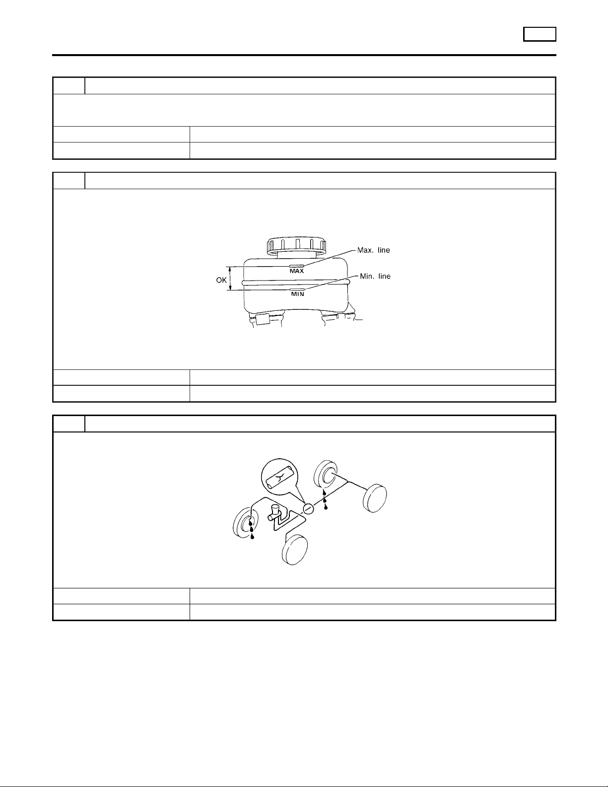
Preliminary Check
TROUBLE DIAGNOSIS — BASIC INSPECTION
ABS
Preliminary Check
1 CHECK BRAKE FLUID
Check brake fluid for contamination.
Has brake fluid been contaminated?
Yes © Replace. GO TO 2.
No © GO TO 2.
2 CHECK BRAKE FLUID LEVEL
Check brake fluid level in reservoir tank.
Low fluid level may indicate brake pad wear or leakage from brake line.
Is brake fluid filled between MAX and MIN lines on reservoir tank ?
Yes © GO TO 3.
No © Fill up brake fluid. GO TO 3.
NGBR0101
SBR451D
3 CHECK BRAKE LINE
Check brake line for leakage.
Is leakage present at or around brake lines, tubes or hoses or are any of these parts cracked or damaged?
Yes © Repair. GO TO 4.
No © GO TO 4.
SBR389C
BR-44
Page 45
TROUBLE DIAGNOSIS — BASIC INSPECTION
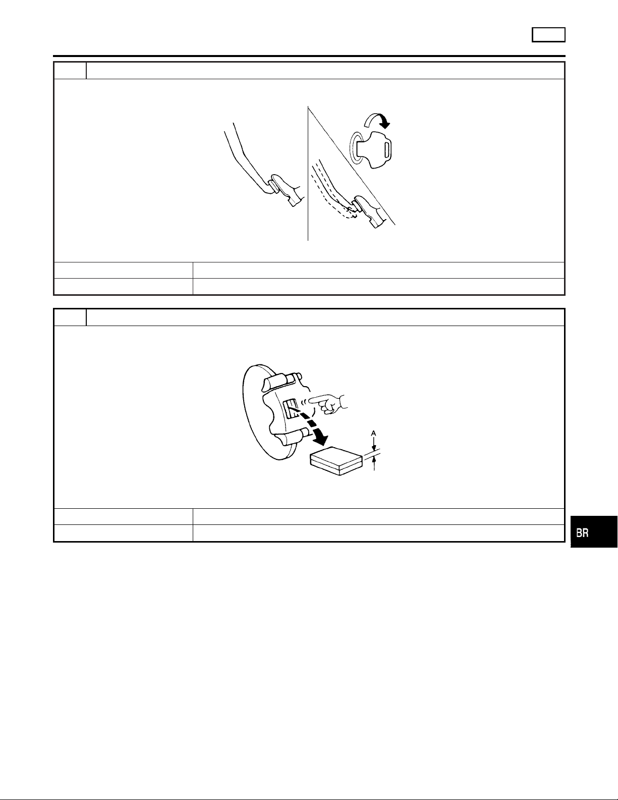
4 CHECK BRAKE BOOSTER OPERATION
Check brake booster for operation and air tightness.
Refer to “On-vehicle Service”, “BRAKE BOOSTER”, BR-16.
Is brake booster airtight and functioning properly?
Yes © GO TO 5.
No © Replace. GO TO 5.
5 CHECK BRAKE PAD AND ROTOR
Check brake pad and rotor.
Refer to BR-19, 20.
ABS
Preliminary Check (Cont’d)
GI
MA
EM
LC
EC
SBR058C
FE
CL
MT
Are brake pads and rotors functioning properly?
Yes © GO TO 6.
No © Replace.
AT
TF
PD
AX
SBR059C
SU
ST
RS
BT
BR-45
HA
SC
EL
IDX
Page 46
TROUBLE DIAGNOSIS — BASIC INSPECTION
Preliminary Check (Cont’d)
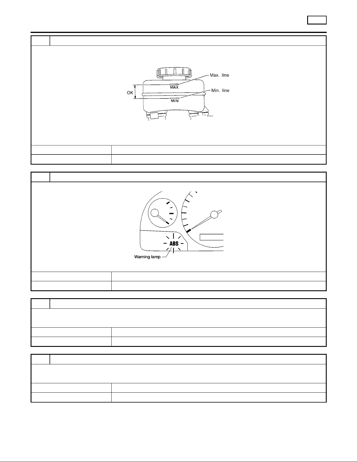
6 RECHECK BRAKE FLUID LEVEL
Check brake fluid level in reservoir tank again.
Is brake fluid filled between MAX and MIN lines on reservoir tank ?
Yes © GO TO 7.
No © Fill up brake fluid.
7 CHECK WARNING LAMP ACTIVATION
Check warning lamp activation.
ABS
SBR451D
Does warning lamp turn on when ignition switch is turned ON?
Yes © GO TO 8.
No © Check fuse, warning lamp bulb and warning lamp circuit.
8 CHECK WARNING LAMP DEACTIVATION
Check warning lamp for deactivation after engine is started.
Does warning lamp turn off when engine is started?
Yes © GO TO 9.
No © Go to Self-diagnosis, BR-41.
9 DRIVE VEHICLE
Drive vehicle at speeds over 30 km/h (19 MPH) for at least one minute.
Does warning lamp remain off after vehicle has been driven at 30 km/h (19 MPH) for at least one minute?
Yes © INSPECTION END
No © Go to Self-diagnosis, BR-41.
ABR838
BR-46
Page 47
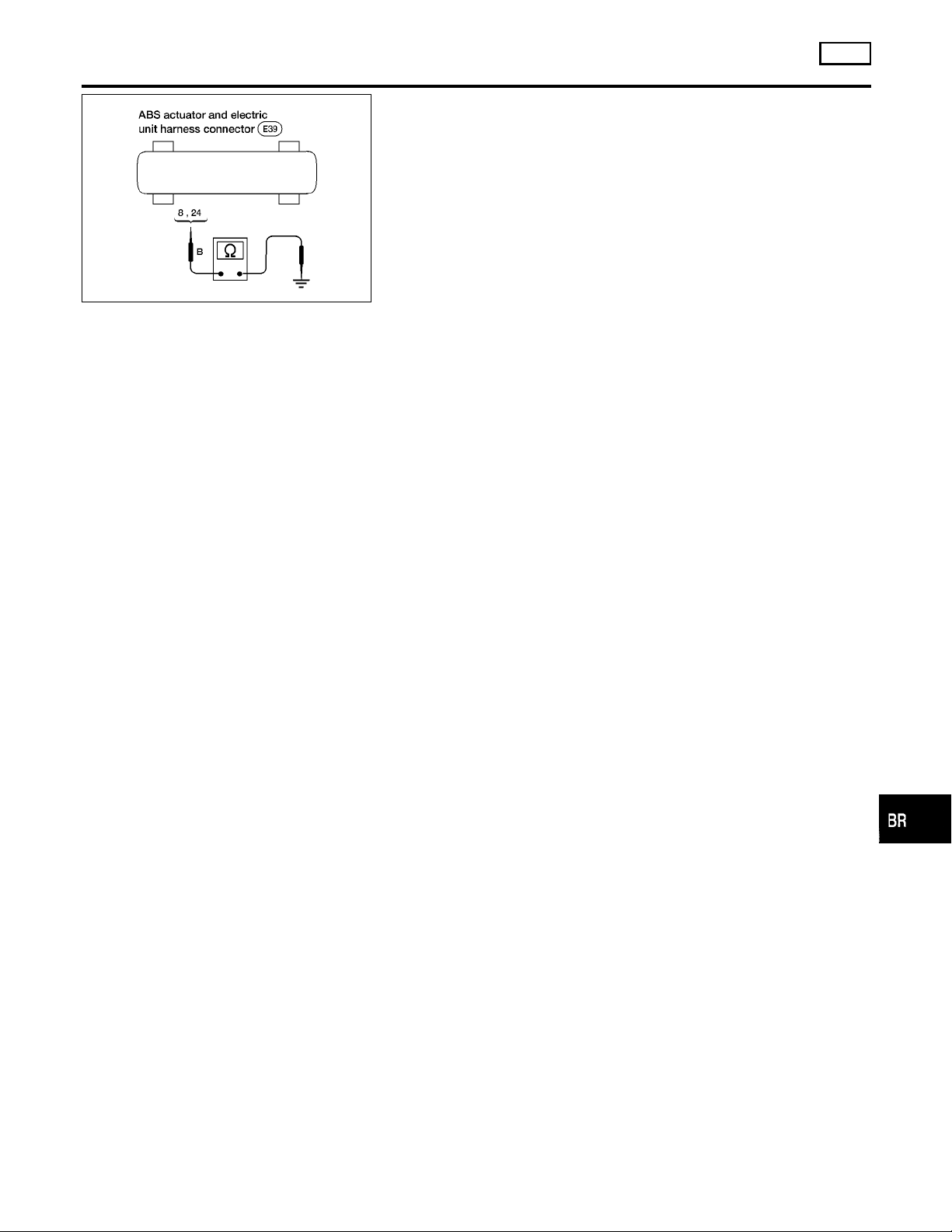
TROUBLE DIAGNOSIS — BASIC INSPECTION
ABS
Ground Circuit Check
ABR882
Ground Circuit Check
ABS ACTUATOR AND ELECTRIC UNIT GROUND
I Check continuity between ABS actuator and electric unit con-
nector terminals and ground.
Continuity should exist.
=NGBR0102
NGBR0102S01
GI
MA
EM
LC
EC
FE
CL
MT
AT
TF
PD
AX
SU
ST
RS
BT
BR-47
HA
SC
EL
IDX
Page 48
TROUBLE DIAGNOSIS — GENERAL DESCRIPTION
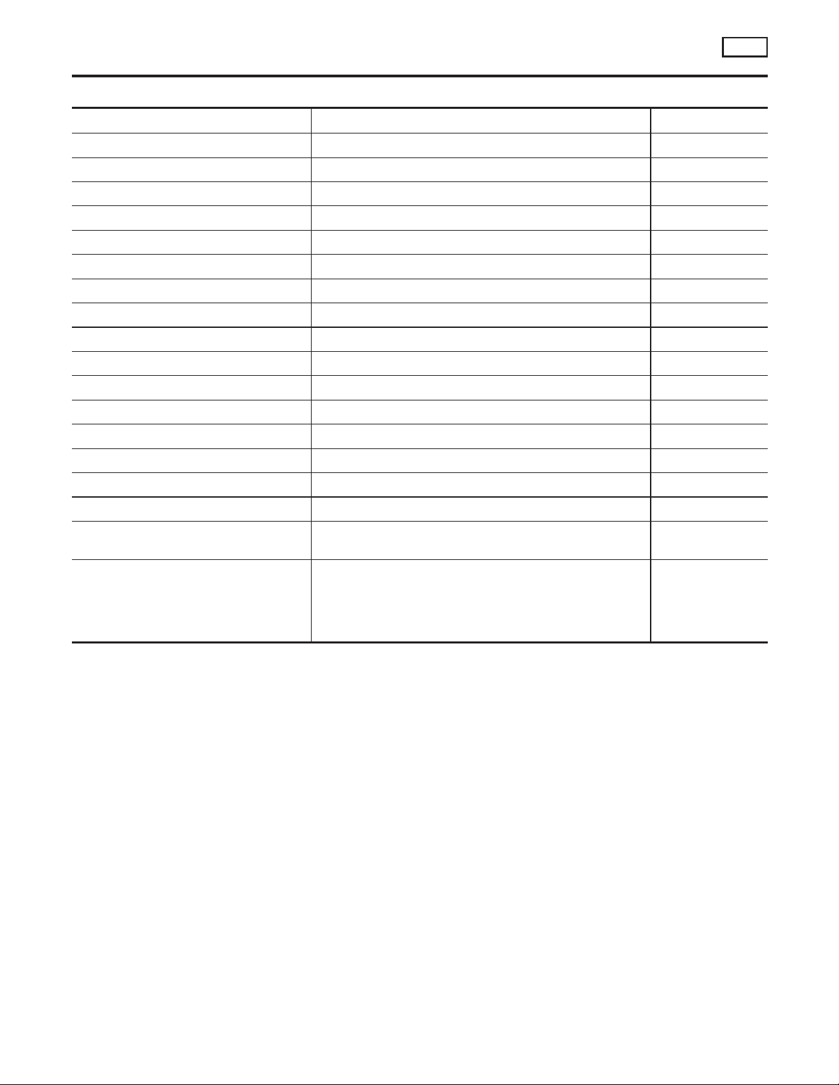
Malfunction Code/Symptom Chart
ABS
Malfunction Code/Symptom Chart
Code No. (No. of warning lamp flashes) Malfunctioning part Reference Page
12 Self-diagnosis could not detect any malfunctions. —
17 ★1 G sensor and circuit (4WD) BR-58
18 ★1 Sensor rotor or abnormal tire size BR-49
21 ★1 Front right sensor BR-49
25 ★1 Front left sensor BR-49
31 ★1 Rear right sensor (4WD) BR-49
35 ★1 Rear left sensor (4WD) or Rear sensor (2WD) BR-49
57 ★2 Power supply (Low voltage) BR-56
61 ★3 Actuator motor or motor relay BR-54
63 Solenoid valve relay BR-52
71 Control unit or Actuator solenoid valve BR-52, 60
ABS works frequently — BR-61
Unexpected pedal action — BR-61
Long stopping distance — BR-63
ABS does not work — BR-63
NGBR0103
Pedal vibration and noise — BR-64
Warning lamp does not come on
when ignition switch is turned ON.
Warning lamp stays on when ignition
switch is turned ON.
★1: If one or more wheels spin on a rough or slippery road for 40 seconds or more, the ABS warning lamp will illuminate. This does
not indicate a malfunction. Only in the case of the short-circuit (Code Nos. 26, 22, 32 and 36), after repair the ABS warning lamp also
illuminates when the ignition switch is turned ON. In this case, drive the vehicle at speeds greater than 30 km/h (19 MPH) for approximately 1 minute as specified in “SELF-DIAGNOSIS PROCEDURE”, BR-41. Check to ensure that the ABS warning lamp goes out while
the vehicle is being driven.
★2: The trouble code “57”, which refers to a low power supply voltage, does not indicate that the ABS control unit is malfunctioning. Do
not replace the ABS control unit with a new one.
★3: The trouble code “61” can sometimes appear when the ABS motor is not properly grounded. If it appears, be sure to check the
condition of the ABS motor ground circuit connection.
Fuse, warning lamp bulb or warning lamp circuit
Control unit
Control unit power supply circuit
Warning lamp bulb circuit
Control unit or control unit connector
Solenoid valve relay stuck
Power supply for solenoid valve relay coil
BR-64
BR-66
BR-48
Page 49
TROUBLE DIAGNOSES FOR SELF-DIAGNOSTIC ITEMS
Wheel Sensor or Rotor
Wheel Sensor or Rotor
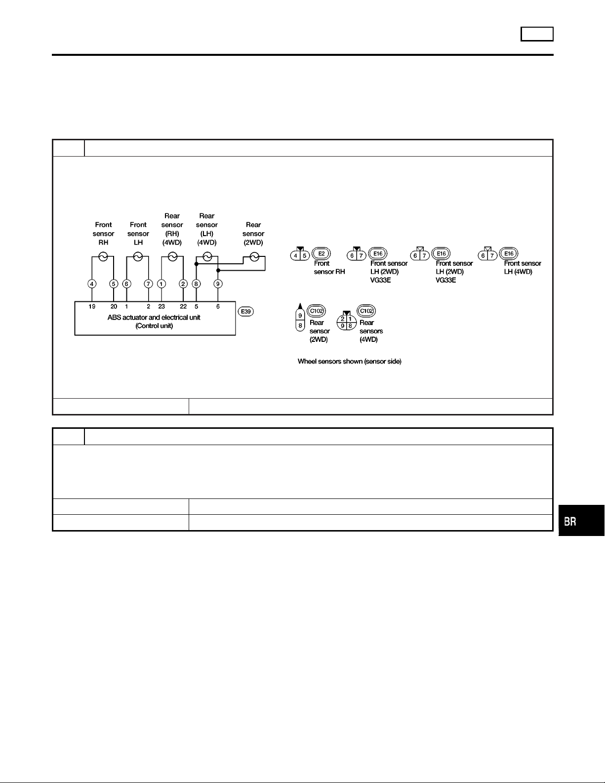
DIAGNOSTIC PROCEDURE
Malfunction code No. 21, 25, 31, 35, or 18
NOTE:
Wheel position should be distinguished by code No. except code
No. 18 (sensor rotor).
ABS
NGBR0104
GI
MA
1 INSPECTION START
Wheel sensor inspection
ABR883
© GO TO 2.
2 CHECK CONNECTOR
1. Disconnect connectors from ABS actuator and electric unit and wheel sensor of malfunction code No. Check terminals
for damage or loose connection. Then reconnect connectors.
2. Carry out self-diagnosis again.
Does warning lamp activate again?
Yes © GO TO 3.
No © INSPECTION END
EM
LC
EC
FE
CL
MT
AT
TF
PD
AX
SU
BR-49
ST
RS
BT
HA
SC
EL
IDX
Page 50
TROUBLE DIAGNOSES FOR SELF-DIAGNOSTIC ITEMS
Wheel Sensor or Rotor (Cont’d)
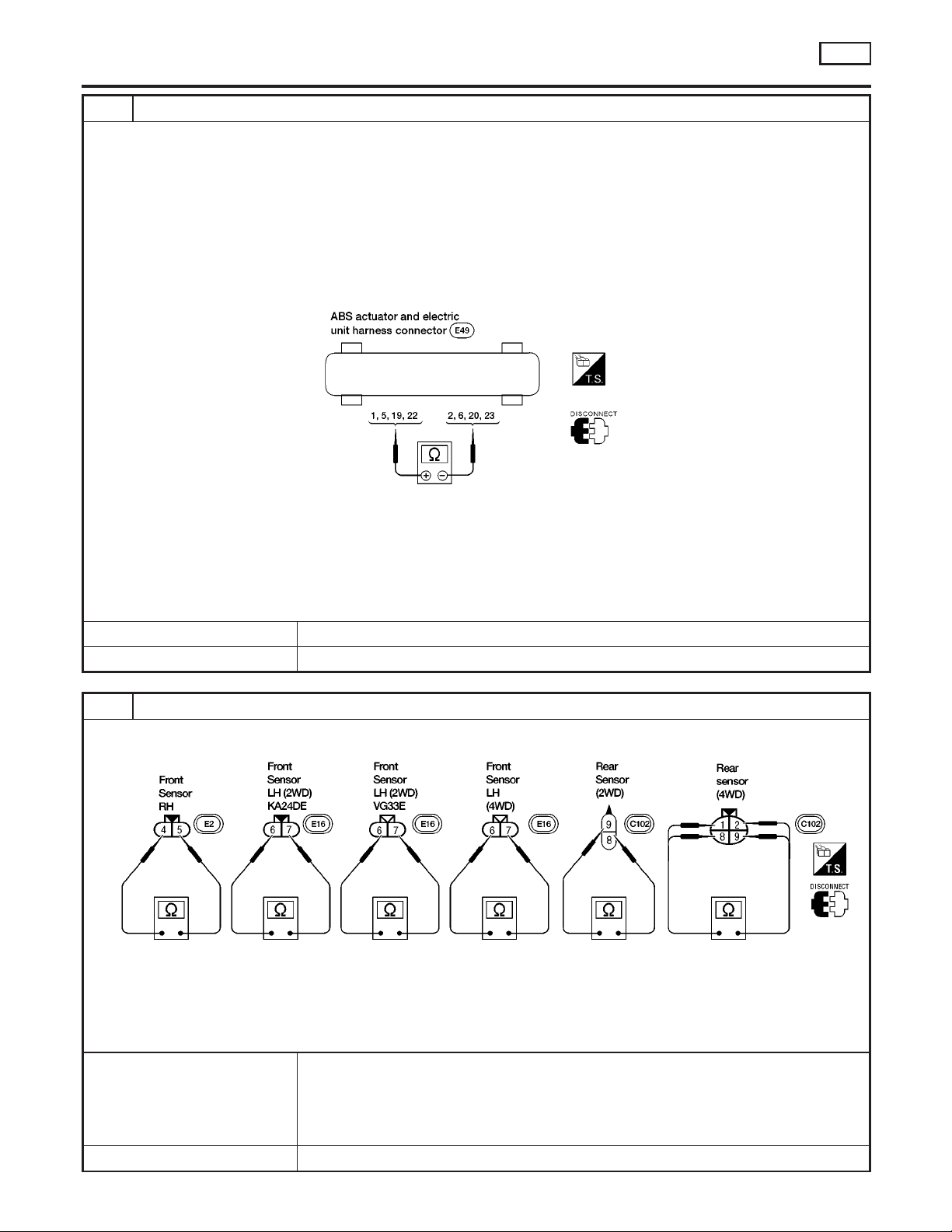
3 CHECK WHEEL SENSOR ELECTRICAL
1. Disconnect ABS actuator and electric unit connector.
2. Check resistance between ABS actuator and electric unit connector E39 terminals
Code No. 21 (Front RH wheel)
Terminals 19 and 20
Code No. 25 (Front LH wheel)
Terminals 1 and 2
Code No. 31 (Rear RH wheel) (4WD)
Terminals 22 and 23
Code No. 35 (4WD: Rear LH wheel, 2WD: Rear wheel)
Terminals 5 and 6
Resistance:
Front 1.28 - 1.92 kΩ
Rear
2WD: 1.05 - 1.35 kΩ
4WD: 1.28 - 1.92 kΩ
Are front and rear resistance values within range listed above?
Yes © GO TO 5.
No © GO TO 4.
ABS
ABR919
4 CHECK WHEEL SENSOR
Check each sensor for resistance.
Resistance:
Front 1.28 - 1.92 kΩ
Rear
2WD 1.05 - 1.35 kΩ
4WD 1.28 - 1.92 kΩ
Are front and rear resistance values within range listed above?
Yes © Check the following.
If NG, repair harness or connectors.
I Harness connectors E2, E16, C102
I Harness for open or short between wheel sensor connectors and ABS actuator and
electric unit
No © Replace wheel sensor.
ABR885
BR-50
Page 51
TROUBLE DIAGNOSES FOR SELF-DIAGNOSTIC ITEMS
5 CHECK TIRE
Check for inflation pressure, wear and size of each tire. (See NOTE)
Are tire pressure and size correct and is tire wear within specifications?
Yes 䊳 GO TO 6.
No 䊳 Adjust tire pressure or replace tire(s). (See NOTE)
ABS
Wheel Sensor or Rotor (Cont’d)
GI
MA
6 CHECK WHEEL BEARING
Check wheel bearing axial end play. (See NOTE)
Is wheel bearing axial end play within specifications? Refer to “On-vehicle Service”, “FRONT AXLE”, AX-4 and
“REAR AXLE”, AX-25.
Yes 䊳 GO TO 7.
No 䊳 Check wheel bearing. Refer to “On-vehicle Service”, “FRONT AXLE”, AX-4 and “REAR
AXLE”, AX-25.
7 CHECK SENSOR ROTOR
Check sensor rotor for teeth damage. (See NOTE)
Is sensor rotor free from damage?
Yes 䊳 Check ABS actuator and electric unit pin terminals for damage or the connection of ABS
actuator and electric unit harness connector. Reconnect ABS actuator and electric unit
harness connector. Then retest.
No 䊳 Replace sensor rotor. (See NOTE)
EM
LC
EC
FE
CL
MT
AT
TF
PD
AX
SU
ST
RS
BT
HA
SC
EL
BR-51
IDX
Page 52
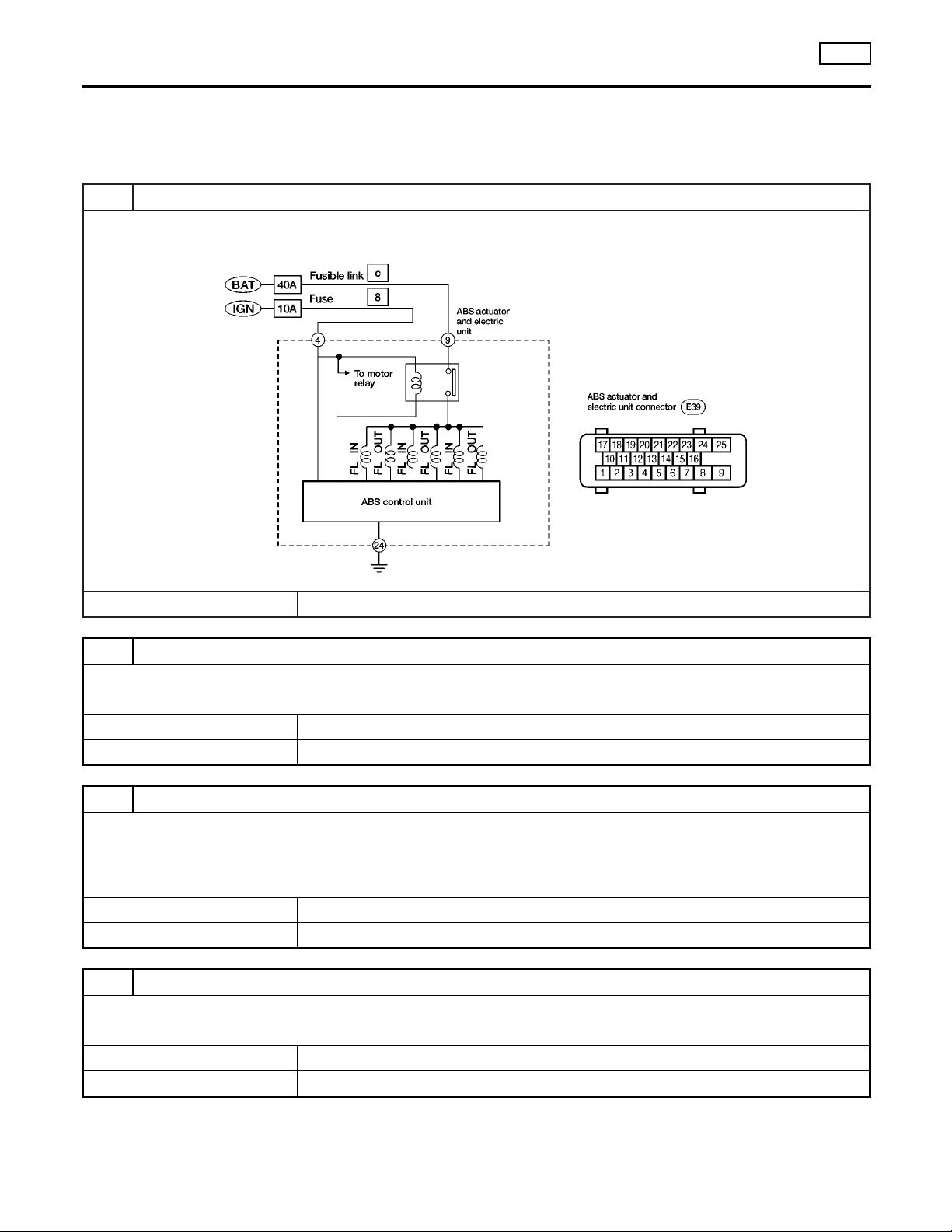
TROUBLE DIAGNOSES FOR SELF-DIAGNOSTIC ITEMS
ABS Actuator Solenoid Valve or Solenoid Valve Relay
ABS Actuator Solenoid Valve or Solenoid Valve
Relay
DIAGNOSTIC PROCEDURE
Malfunction code No. 71
1 INSPECTION START
Solenoid valve relay inspection
ABS
=NGBR0105
© GO TO 2.
2 CHECK FUSIBLE LINK
Check 40A fusible link c. For fusible link layout, refer to “POWER SUPPLY ROUTING”,
Is fusible link OK?
Yes © GO TO 3.
No © GO TO 6.
3 CHECK CONNECTOR
1. Disconnect connector from ABS actuator and electric unit. Check terminals for damage or loose connection. Then
reconnect connector.
2. Carry out self-diagnosis again.
Does warning lamp activate again?
Yes © GO TO 4.
No © INSPECTION END
4 CHECK ABS ACTUATOR AND ELECTRIC UNIT GROUND CIRCUIT
Refer to “ABS ACTUATOR AND ELECTRIC UNIT GROUND” in “Ground Circuit Check”, BR-47.
Is ground circuit OK?
Yes © GO TO 5.
No © Repair harness or connector.
EL-9
.
ABR886
BR-52
Page 53
TROUBLE DIAGNOSES FOR SELF-DIAGNOSTIC ITEMS
ABS Actuator Solenoid Valve or Solenoid Valve Relay (Cont’d)
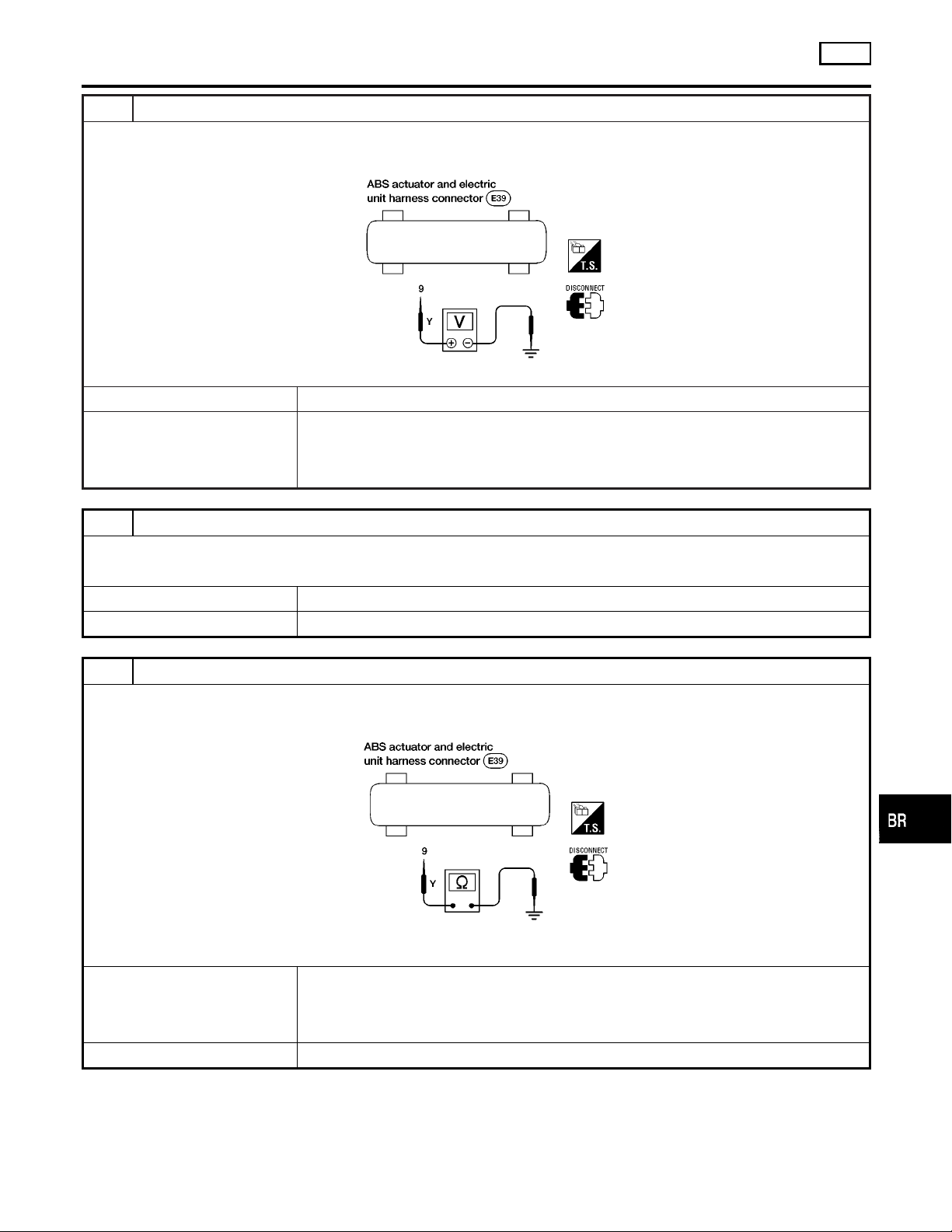
5 CHECK SOLENOID VALVE POWER SUPPLY CIRCUIT
1. Disconnect ABS actuator and electric unit connector.
2. Check voltage between ABS actuator and electric unit connector E39 terminal 9 and ground.
ABS
GI
MA
EM
LC
Does battery voltage exist?
Yes © Replace ABS actuator and electric unit.
No © Check the following.
If NG, repair harness or connectors.
I Harness connector E39
I Harness for open or short between ABS actuator and electric unit and fusible link
6 REPLACE FUSIBLE LINK
Replace fusible link.
Does the fuse blow out when ignition switch is turned ON?
Yes © GO TO 7.
No © INSPECTION END
7 CHECK SOLENOID VALVE RELAY POWER SUPPLY CIRCUIT FOR SHORT
1. Disconnect battery cable and ABS actuator and electric unit connector.
2. Check continuity between ABS actuator and electric unit connector E39 terminal 9 and ground.
ABR887
EC
FE
CL
MT
AT
TF
PD
AX
SU
Continuity should not exist.
Does continuity exist?
Yes © Check the following.
If NG, repair harness or connector.
I Harness connector E39
I Harness for open or short between ABS actuator and electric unit and fusible link
No © Replace ABS actuator and electric unit.
BR-53
ST
ABR888
RS
BT
HA
SC
EL
IDX
Page 54
TROUBLE DIAGNOSES FOR SELF-DIAGNOSTIC ITEMS
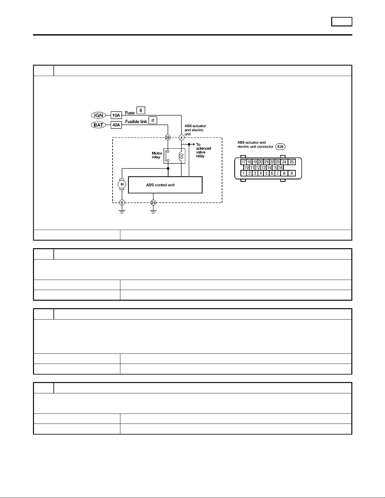
Motor Relay or Motor
1 INSPECTION START
ABS motor relay inspection
Motor Relay or Motor
DIAGNOSTIC PROCEDURE
Malfunction code No. 61
ABS
=NGBR0106
ABR889
© GO TO 2.
2 CHECK FUSIBLE LINK
Check 40A fusible link d. For fusible link layout, refer to “POWER SUPPLY ROUTING”,
Is fusible link OK?
Yes © GO TO 3.
No © GO TO 6.
3 CHECK CONNECTOR
1. Disconnect ABS actuator and electric unit connector. Check terminals for damage or loose connection. Then reconnect
connector.
2. Carry out self-diagnosis again.
Does warning lamp activate again?
Yes © GO TO 4.
No © INSPECTION END
4 CHECK ABS ACTUATOR AND ELECTRIC UNIT GROUND CIRCUIT
Refer to “ABS ACTUATOR AND ELECTRIC UNIT GROUND” in “Ground Circuit Check”, BR-47.
Is ground circuit OK?
Yes © GO TO 5.
No © Repair harness or connector.
EL-9
.
BR-54
Page 55
TROUBLE DIAGNOSES FOR SELF-DIAGNOSTIC ITEMS
Motor Relay or Motor (Cont’d)
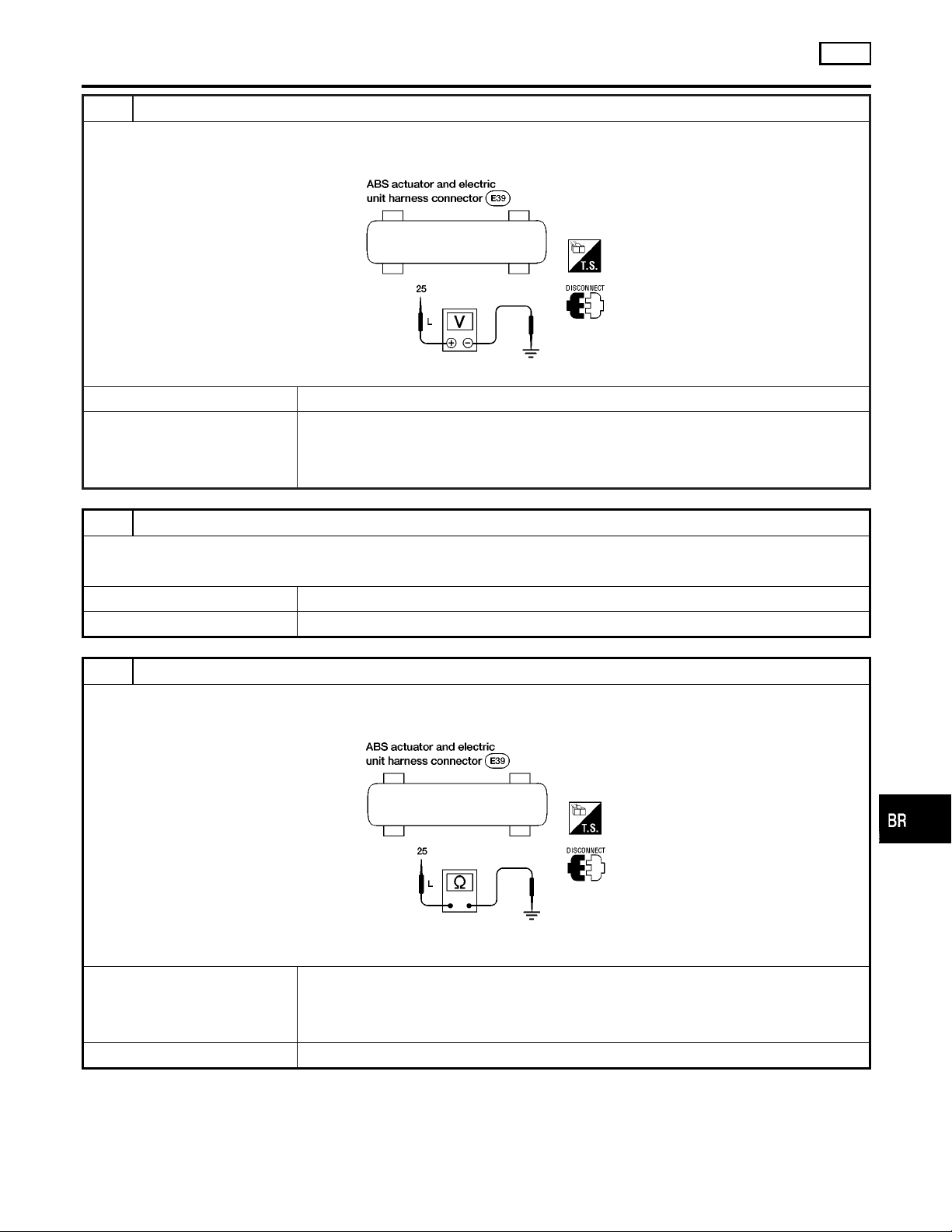
5 CHECK MOTOR RELAY POWER SUPPLY CIRCUIT
1. Disconnect ABS actuator and electric unit connector.
2. Check voltage between ABS actuator and electric unit connector E39 terminal 25 and ground.
ABS
GI
MA
EM
LC
Does battery voltage exist?
Yes © Replace ABS actuator and electric unit.
No © Check the following.
If NG, repair harness or connector.
I Harness connector E39
I Harness for open or short between ABS actuator and electric unit and fusible link
6 REPLACE FUSIBLE LINK
Replace fusible link.
Does the fusible link blow out when ignition switch is turned ON?
Yes © GO TO 7.
No © INSPECTION END
7 CHECK ABS ACTUATOR MOTOR POWER SUPPLY CIRCUIT FOR SHORT
1. Disconnect battery cable and ABS actuator and electric unit connector.
2. Check continuity between ABS actuator and electric unit connector E39 terminal 25 and ground.
ABR890
EC
FE
CL
MT
AT
TF
PD
AX
SU
Continuity should not exist.
Does continuity exist?
Yes © Check the following.
If NG, repair harness or connector.
I Harness connector E39
I Harness for open or short between ABS actuator and electric unit and fusible link
No © Replace ABS actuator and electric unit.
BR-55
ST
ABR891
RS
BT
HA
SC
EL
IDX
Page 56
TROUBLE DIAGNOSES FOR SELF-DIAGNOSTIC ITEMS
Low Voltage
Low Voltage
DIAGNOSTIC PROCEDURE
Malfunction code No. 57
1 INSPECTION START
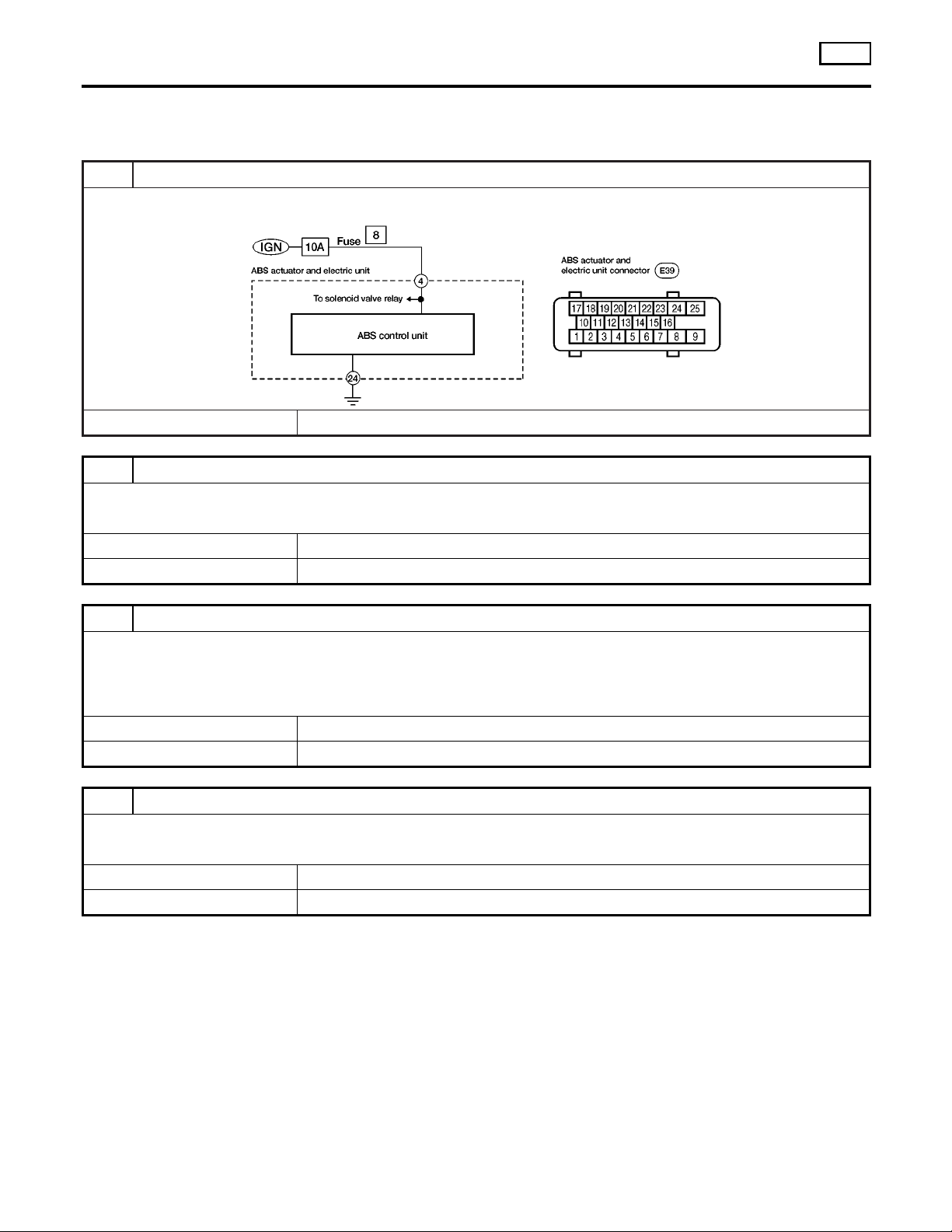
ABS actuator and electric unit power supply and ground circuit inspection
© GO TO 2.
2 CHECK FUSE
Check 10A fuse No. 8. For fuse layout, refer to “POWER SUPPLY ROUTING”,
Is fuse OK?
Yes © GO TO 3.
No © GO TO 6.
EL-9
ABS
NGBR0107
ABR892
.
3 CHECK CONNECTOR
1. Disconnect ABS actuator and electric unit connector. Check terminals for damage or loose connections. Then reconnect connector.
2. Carry out self-diagnosis again.
Does warning lamp activate again?
Yes © GO TO 4.
No © INSPECTION END
4 CHECK ABS ACTUATOR AND ELECTRIC UNIT GROUND CIRCUIT
Refer to “ABS ACTUATOR AND ELECTRIC UNIT GROUND” in “Ground Circuit Check”, BR-47.
Is ground circuit OK?
Yes © GO TO 5.
No © Repair harness or connector.
BR-56
Page 57
TROUBLE DIAGNOSES FOR SELF-DIAGNOSTIC ITEMS
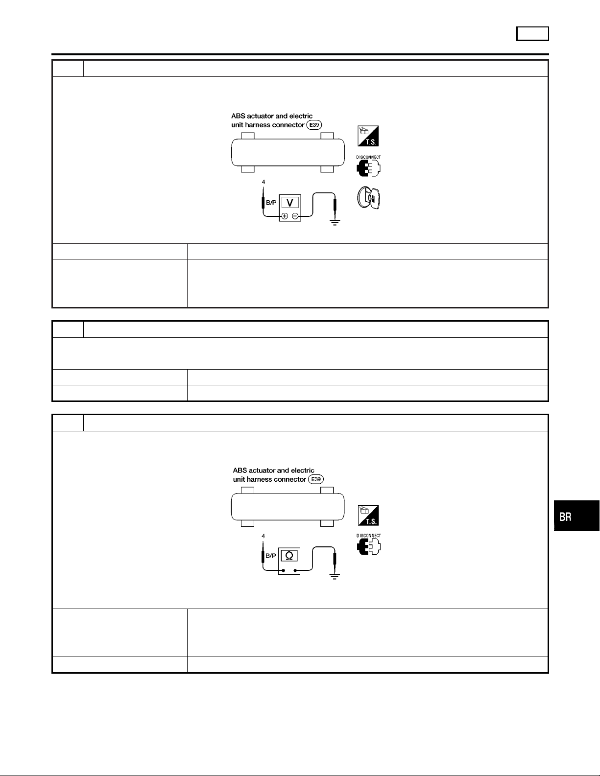
5 CHECK ABS ACTUATOR AND ELECTRIC UNIT POWER SUPPLY CIRCUIT
1. Disconnect ABS actuator and electric unit connector.
2. Check voltage between ABS actuator and electric unit connector E39 terminal 4 and ground.
ABS
Low Voltage (Cont’d)
GI
MA
EM
LC
Does battery voltage exist when ignition switch is turned ON?
Yes © Replace ABS actuator and electric unit.
No © Check the following.
If NG, repair harness or connector.
I Harness connector E39
I Harness for open or short between ABS actuator and electric unit and fuse
6 REPLACE FUSE
Replace fuse.
Does the fuse blow out when ignition switch is turned ON?
Yes © GO TO 7.
No © INSPECTION END
7 CHECK ABS ACTUATOR AND ELECTRIC UNIT POWER SUPPLY CIRCUIT FOR SHORT
1. Disconnect battery cable and ABS actuator and electric unit connector.
2. Check continuity between ABS actuator and electric unit connector E39 terminal 4 and ground.
ABR893
EC
FE
CL
MT
AT
TF
PD
AX
SU
Continuity should not exist.
Does continuity exist?
Yes © Check the following.
If NG, repair harness or connector.
I Harness connector E39
I Harness for open or short between ABS actuator and electric unit and fuse
No © Replace ABS actuator and electric unit.
BR-57
ST
ABR894
RS
BT
HA
SC
EL
IDX
Page 58
TROUBLE DIAGNOSES FOR SELF-DIAGNOSTIC ITEMS
G Sensor and Circuit
G Sensor and Circuit
DIAGNOSTIC PROCEDURE
Malfunction code No. 17
1 INSPECTION START
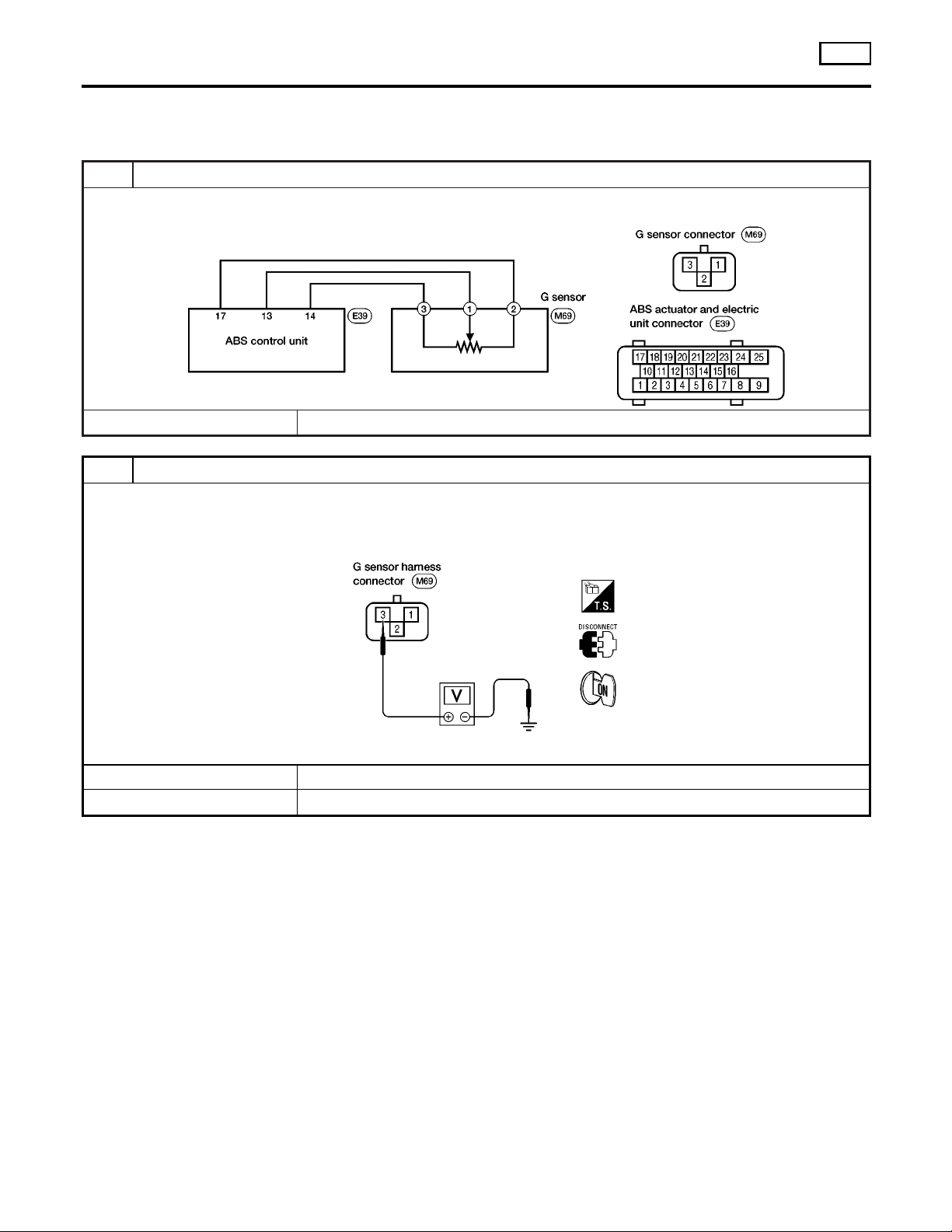
G sensor inspection
© GO TO 2.
2 CHECK G SENSOR POWER
1. Turn ignition switch OFF and disconnect G sensor harness connector.
2. Turn ignition switch ON.
3. Check voltage between G sensor harness connector M69 terminal 3 and ground.
ABS
NGBR0118
ABR895
Yes © GO TO 3.
No © GO TO 4.
ABR896
Does approx. 5V exist?
BR-58
Page 59
TROUBLE DIAGNOSES FOR SELF-DIAGNOSTIC ITEMS
G Sensor and Circuit (Cont’d)
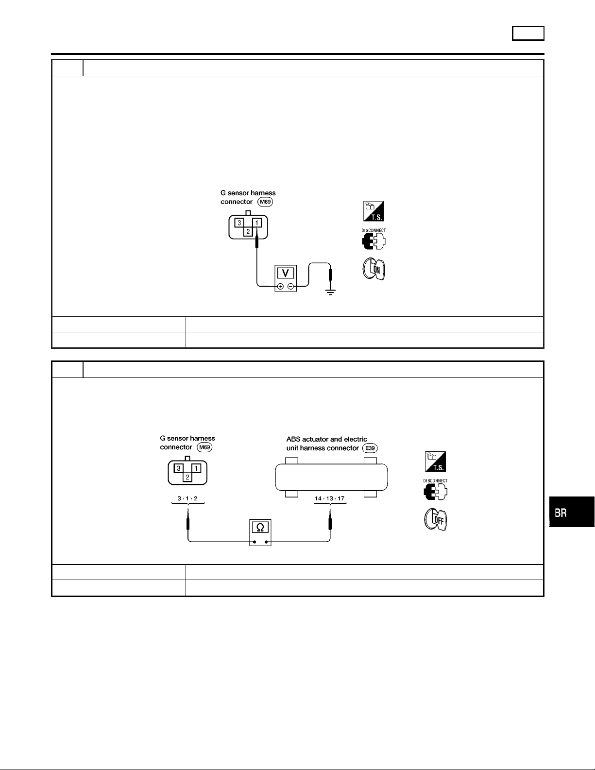
3 CHECK G SENSOR
1. Turn ignition switch OFF.
2. Remove G sensor from bracket.
3. Reconnect harness connector to G sensor and hold sensor in same attitude/position as when installed in vehicle.
I Check voltage between G sensor connector M69 terminal 1 and ground for the following tests.
There should be approx. 2.5V.
4. Turn sensor 90° with connector point up.
I There should be approx. 3.7V.
5. Turn sensor 180° with connector pointing down.
I There should be approx. 1.3V.
ABS
GI
MA
EM
LC
EC
FE
ABR897
Were the voltage readings correct for steps 3, 4 and 5?
Yes © GO TO 4.
No © Replace G Sensor.
4 CHECK G SENSOR CIRCUIT
1. Disconnect ABS actuator and electric unit connector.
2. Check continuity from G sensor connector M69 terminal 3 to ABS actuator and electric unit connector E39 terminal 14.
3. Check continuity from G sensor connector M69 terminal 1 to ABS actuator and electric unit connector E39 terminal 13.
4. Check continuity from G sensor connector M69 terminal 2 to ABS actuator and electric unit connector E39 terminal 17.
ABR898
Does continuity exist?
Yes © Replace ABS actuator and electric unit.
No © Repair harness or connector.
CL
MT
AT
TF
PD
AX
SU
ST
RS
BR-59
BT
HA
SC
EL
IDX
Page 60
TROUBLE DIAGNOSES FOR SELF-DIAGNOSTIC ITEMS
Control Unit
Control Unit
DIAGNOSTIC PROCEDURE
Malfunction code No. 71
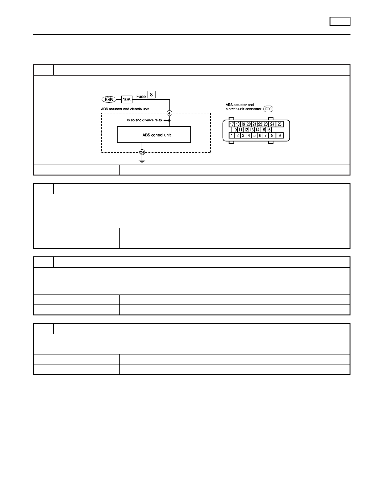
1 INSPECTION START
ABS actuator and electric unit power supply and ground circuit inspection
© GO TO 2.
2 CHECK CONNECTOR
1. Disconnect ABS actuator and electric unit connector.
Check terminals for damage or loose connection. Then reconnect connector.
2. Carry out self-diagnosis again.
Does warning lamp activate again?
Yes © GO TO 3.
No © INSPECTION END
ABS
=NGBR0108
ABR899
3 CHECK ABS ACTUATOR AND ELECTRIC UNIT POWER SUPPLY CIRCUIT
Check voltage. Refer to “5. CHECK ABS ACTUATOR AND ELECTRIC UNIT POWER SUPPLY CIRCUIT” in “DIAGNOSTIC PROCEDURE”, “Low Voltage”, BR-56.
Does battery voltage exist when ignition switch is turned ON?
Yes © GO TO 4.
No © Repair.
4 CHECK WARNING LAMP INDICATION
Does warning lamp indicate code No. 71 again?
YesorNo
Yes © Replace ABS actuator and electric unit.
No © Inspect the system according to the code No.
BR-60
Page 61
TROUBLE DIAGNOSES FOR SYMPTOMS
ABS
1. ABS Works Frequently
1. ABS Works Frequently
1 CHECK BRAKE FLUID PRESSURE
Check brake fluid pressure distribution.
Is brake fluid pressure distribution normal?
Yes © GO TO 2.
No © Repair. Then perform Preliminary Check.
Refer to BR-44.
2 CHECK WHEEL SENSOR
1. Check wheel sensor connector for terminal damage or loose connections.
2. Perform wheel sensor mechanical check.
Refer to “7. CHECK SENSOR ROTOR” in “DIAGNOSTIC PROCEDURE”, “Wheel Sensor or Rotor”, BR-49.
Is wheel sensor mechanism OK?
Yes © GO TO 3.
No © Repair.
3 CHECK FRONT AXLE
Check front axles for excessive looseness. Refer to “Front Wheel Bearing”, “ON-VEHICLE SERVICE”,
Is front axle installed properly?
Yes © Go to “3. CHECK WARNING LAMP INDICATION” in “2. Unexpected Pedal Action”,
BR-61.
No © Repair.
AX-4
.
NGBR0109
GI
MA
EM
LC
EC
FE
CL
MT
AT
TF
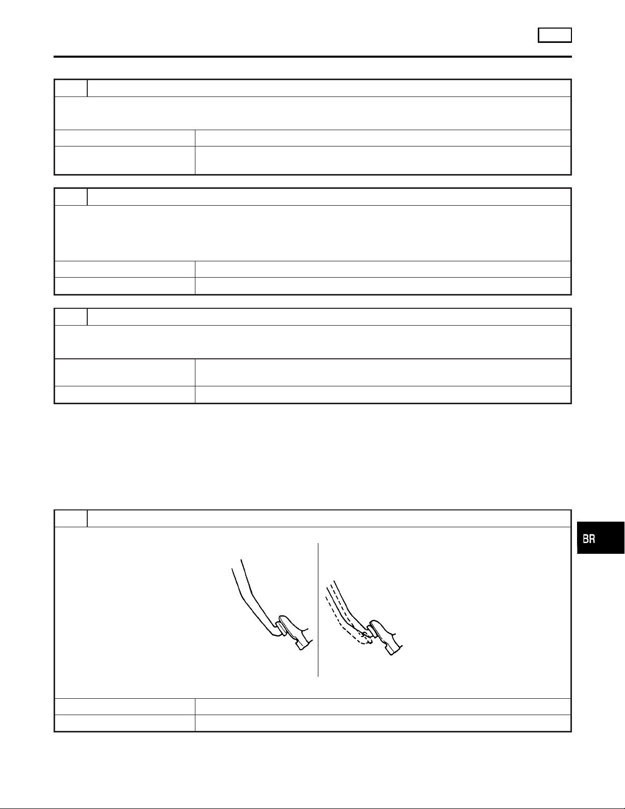
2. Unexpected Pedal Action
1 CHECK BRAKE PEDAL STROKE
Check brake pedal stroke.
Is brake pedal stroke excessively large?
Yes © Perform Preliminary Check. Refer to BR-44.
No © GO TO 2.
NGBR0110
SBR540A
PD
AX
SU
ST
RS
BT
HA
SC
BR-61
EL
IDX
Page 62
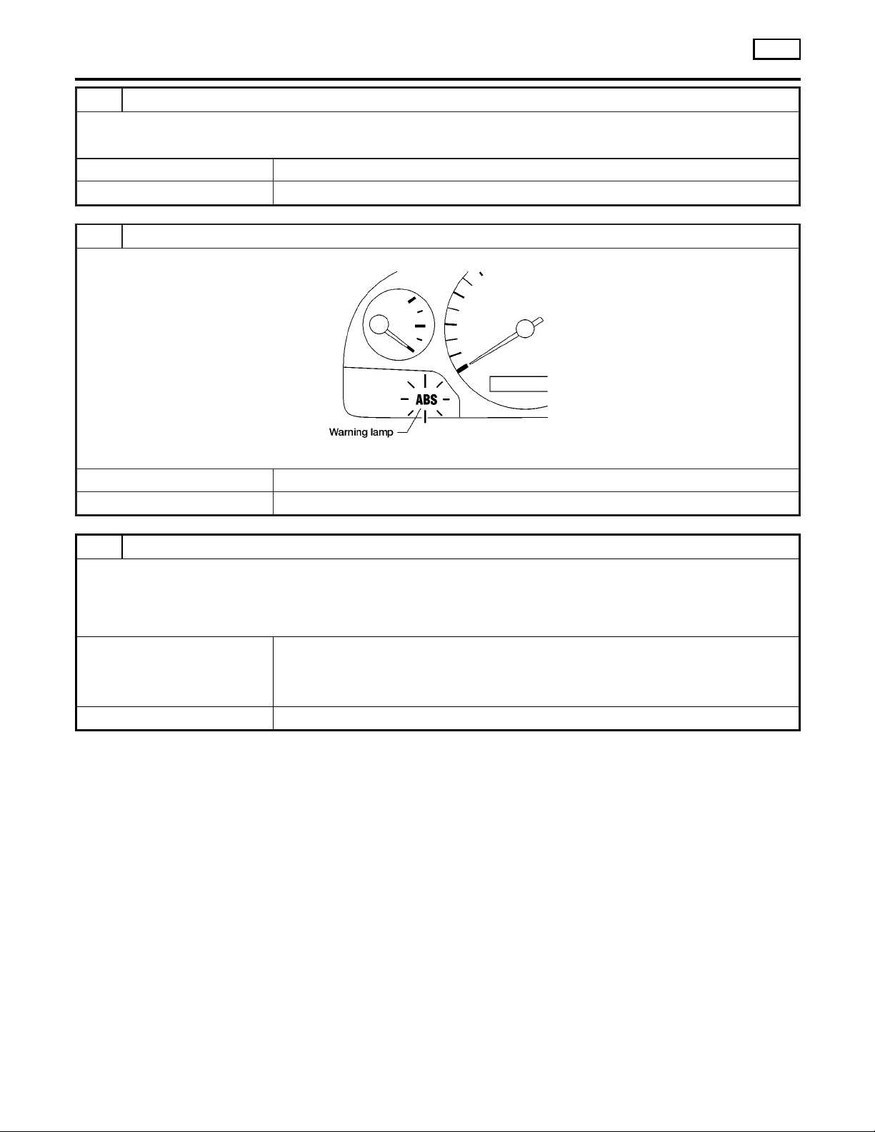
TROUBLE DIAGNOSES FOR SYMPTOMS
2. Unexpected Pedal Action (Cont’d)
2 CHECK MECHANICAL BRAKE SYSTEM PERFORMANCE
Disconnect ABS actuator and electric unit connector and check whether brake is effective.
Does brake system function properly when brake pedal is depressed?
Yes © GO TO 3.
No © Perform Preliminary Check. Refer to BR-44.
3 CHECK WARNING LAMP INDICATION
Ensure warning lamp remains off while driving.
Is warning lamp turned off?
Yes © GO TO 4.
No © Carry out self-diagnosis. Refer to BR-41.
ABS
ABR838
4 CHECK WHEEL SENSOR
1. Check wheel sensor connector for terminal damage or loose connection.
2. Perform wheel sensor mechanical check. Refer to “7. CHECK SENSOR ROTOR” in “DIAGNOSTIC PROCEDURE”,
“Wheel Sensor or Rotor”, BR-49.
Is wheel sensor mechanism OK?
Yes © Check ABS actuator and electric unit pin terminals for damage or the connection of ABS
actuator and electric unit harness connector.
Reconnect ABS actuator and electric unit harness connector.
Then retest.
No © Repair.
BR-62
Page 63
TROUBLE DIAGNOSES FOR SYMPTOMS
ABS
3. Long Stopping Distance
3. Long Stopping Distance
1 CHECK MECHANICAL BRAKE SYSTEM PERFORMANCE
Disconnect ABS actuator and electric unit connector and check whether stopping distance is still long.
Does brake system function properly when brake pedal is depressed?
Yes © Perform Preliminary Check and air bleeding (if necessary).
No © Go to “3. CHECK WARNING LAMP INDICATION” in “2. Unexpected Pedal Action”,
BR-61.
NOTE:
Stopping distance may be longer for vehicles without ABS when
road condition is slippery.
4. ABS Does Not Work
1 CHECK WARNING LAMP INDICATION
Does the ABS warning lamp activate?
YesorNo
Yes © Carry out self-diagnosis. Refer to BR-41.
No © Go to “3. CHECK WARNING LAMP INDICATION” in “2. Unexpected Pedal Action”,
BR-61.
=NGBR0111
NGBR0112
GI
MA
EM
LC
EC
FE
CL
MT
AT
TF
PD
NOTE:
ABS does not work when vehicle speed is under 10 km/h (6 MPH).
AX
SU
ST
RS
BT
HA
SC
EL
BR-63
IDX
Page 64
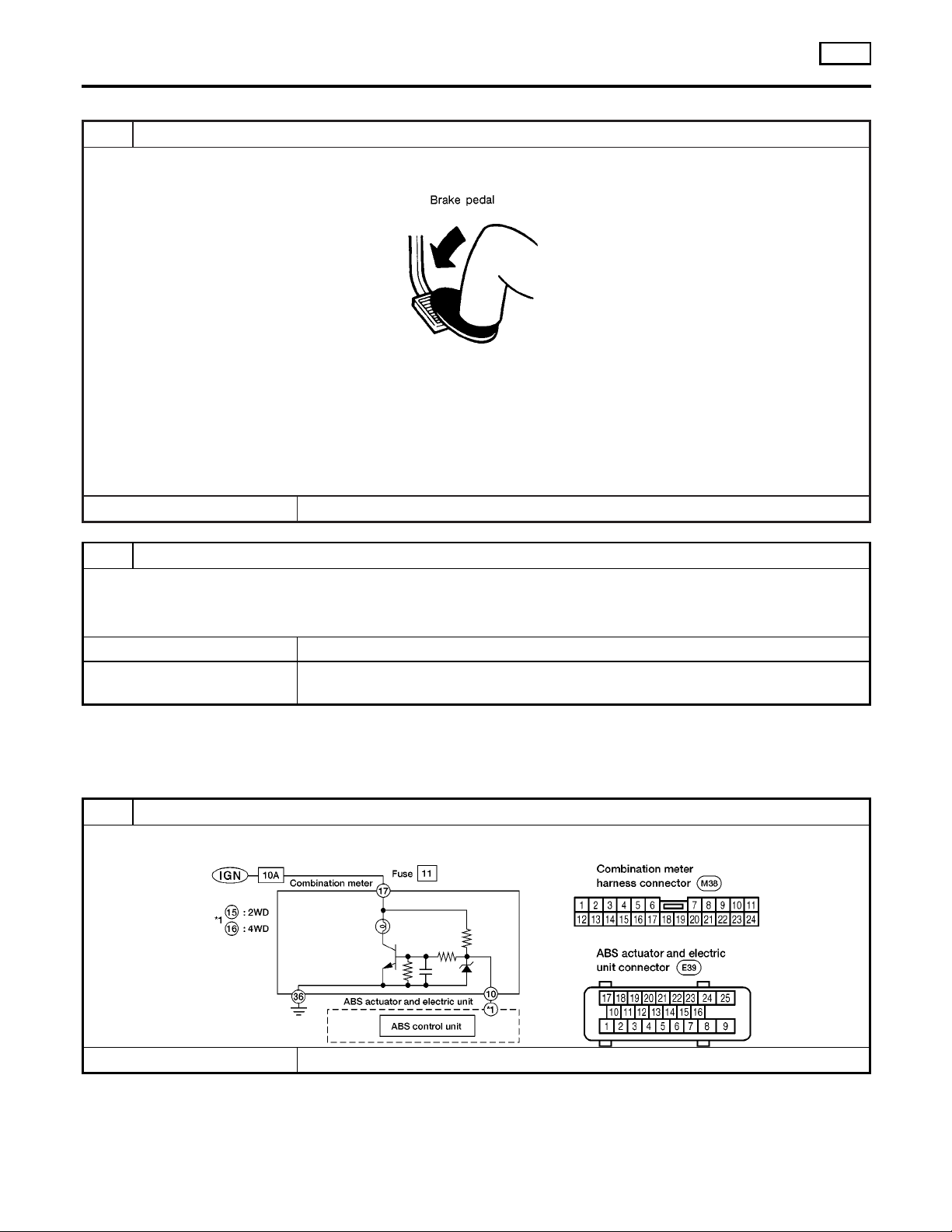
5. Pedal Vibration and Noise
TROUBLE DIAGNOSES FOR SYMPTOMS
ABS
5. Pedal Vibration and Noise
1 INSPECTION START
Pedal vibration and noise inspection
NOTE:
ABS may operate and cause vibration under any of the following conditions.
I Applying brake gradually when shifting or operating clutch.
I Low friction (slippery) road.
I High speed cornering.
I Driving over bumps and pot holes.
I Engine speed is over 5,000 rpm with vehicle stopped.
© GO TO 2.
NGBR0113
SAT797A
2 CHECK SYMPTOM
1. Apply brake.
2. Start engine.
Does the symptom appear only when engine is started?
Yes © Carry out self-diagnosis. Refer to BR-41.
No © Go to “3. CHECK WARNING LAMP INDICATION” in “2. Unexpected Pedal Action”,
BR-61.
6. Warning Lamp Does Not Come On When Ignition Switch Is Turned On
1 INSPECTION START
Warning lamp circuit inspection
NGBR0114
© GO TO 2.
ABR900
BR-64
Page 65
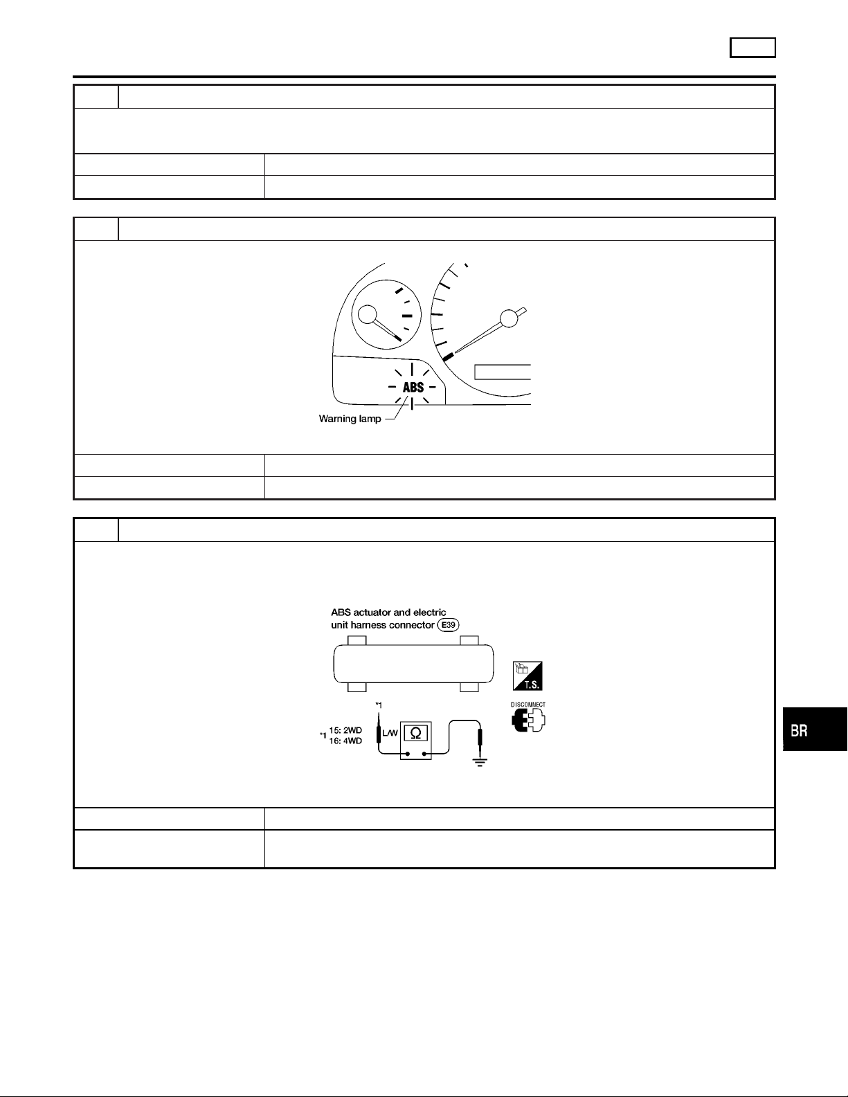
TROUBLE DIAGNOSES FOR SYMPTOMS
6. Warning Lamp Does Not Come On When Ignition Switch Is Turned On (Cont’d)
2 CHECK FUSE
Check 10A fuse No. 11. For fuse layout, refer to “POWER SUPPLY ROUTING”,
Is fuse OK?
Yes © GO TO 3.
No © Replace fuse.
EL-9
ABS
.
GI
MA
3 CHECK WARNING LAMP ACTIVATE
Disconnect ABS actuator and electric unit connector.
ABR838
Does the warning lamp activate?
Yes © Replace ABS actuator and electric unit.
No © GO TO 4.
4 CHECK HARNESS FOR SHORT
1. Disconnect ABS actuator and electric unit connector E39 and combination meter connector M38.
2. Check continuity between ABS actuator and electric unit connector E39 (body side) terminal 15 (2WD) or terminal 16
(4WD) and ground.
EM
LC
EC
FE
CL
MT
AT
TF
PD
Continuity should not exist.
Does continuity exist?
Yes © Repair harness or connectors.
No © Check combination meter.
Refer to “WARNING LAMPS”,
EL-87
AX
SU
ABR901
ST
RS
.
BT
HA
SC
EL
BR-65
IDX
Page 66
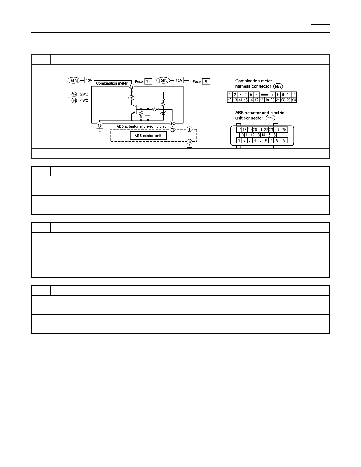
TROUBLE DIAGNOSES FOR SYMPTOMS
7. Warning Lamp Stays On When Ignition Switch Is Turned On
7. Warning Lamp Stays On When Ignition
Switch Is Turned On
1 INSPECTION START
ABS control unit inspection
© GO TO 2.
2 CHECK FUSE
Check 10A fuse No. 8. For fuse layout, refer to “POWER SUPPLY ROUTING”,
Is fuse OK?
Yes © GO TO 3.
No © GO TO 8.
EL-9
ABS
NGBR0115
ABR902
.
3 CHECK HARNESS CONNECTOR
Check ABS actuator and electric unit pin terminals for damage or bad connection of ABS actuator and electric unit harness
connector. Reconnect ABS actuator and electric unit harness connector. Then retest.
Does warning lamp stay on when ignition switch is turned ON?
Yes © GO TO 4.
No © INSPECTION END
4 CHECK ABS ACTUATOR AND ELECTRIC UNIT GROUND CIRCUIT
Refer to “ABS ACTUATOR AND ELECTRIC UNIT GROUND” in “Ground Circuit Check”, BR-47.
Is ground circuit OK?
Yes © GO TO 5.
No © Repair harness or connector.
BR-66
Page 67
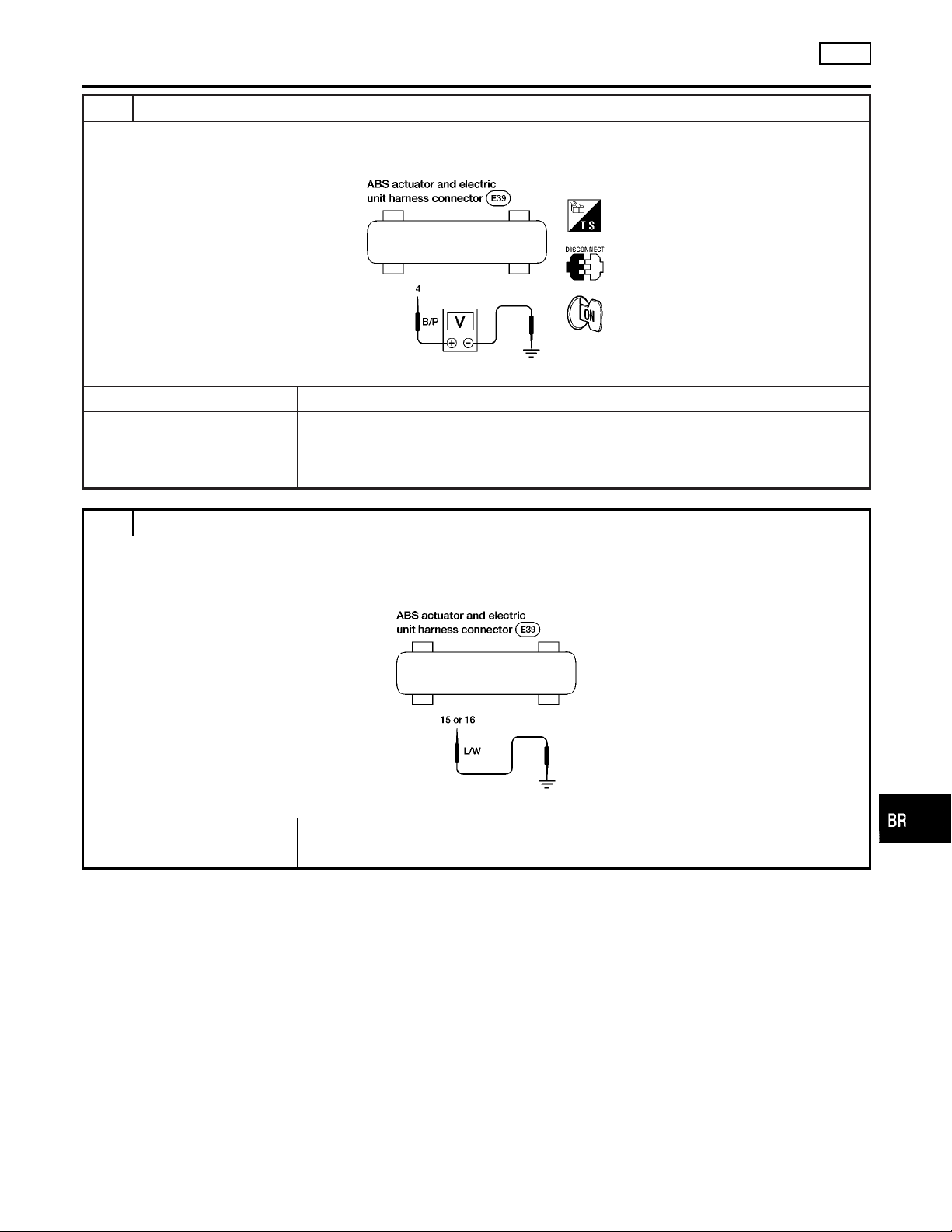
TROUBLE DIAGNOSES FOR SYMPTOMS
7. Warning Lamp Stays On When Ignition Switch Is Turned On (Cont’d)
5 CHECK ABS ACTUATOR AND ELECTRIC UNIT POWER SUPPLY CIRCUIT
1. Disconnect ABS actuator and electric unit connector.
2. Check voltage between ABS actuator and electric unit connector E39 terminal 4 and ground.
ABS
GI
MA
EM
LC
ABR893
Does battery voltage exist when ignition switch is turned ON?
Yes © GO TO 6.
No © Check the following.
If NG, repair harness or connector.
I Harness connector E39
I Harness for open or short between ABS actuator and electric unit and fuse
6 CHECK WARNING LAMP
1. Disconnect ABS actuator and electric unit connector.
2. Connect suitable wire between ABS actuator and electric unit connector E39 terminal 15 (2WD) terminal 16 (4WD) and
ground.
ABR903
Does the warning lamp deactivate?
Yes © Replace ABS actuator and electric unit.
No © GO TO 7.
EC
FE
CL
MT
AT
TF
PD
AX
SU
ST
BR-67
RS
BT
HA
SC
EL
IDX
Page 68
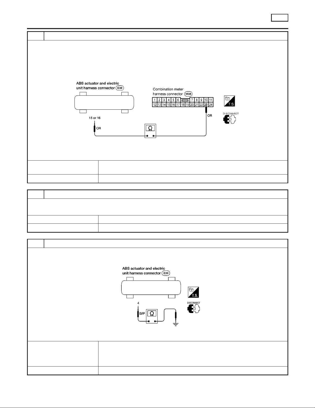
TROUBLE DIAGNOSES FOR SYMPTOMS
7. Warning Lamp Stays On When Ignition Switch Is Turned On (Cont’d)
7 CHECK ABS WARNING LAMP CONTROL CIRCUIT FOR OPEN
1. Disconnect combination meter connector M38.
2. Check continuity between combination meter connector M38 (body side) terminal 10 and ABS actuator and electric unit
connector E39 (body side) terminal 15 (2WD) or terminal 16 (4WD).
NOTE:
Connect positive lead of multimeter to combination meter connector M38 (body side) terminal 10 and negative lead to
ABS actuator and electric unit connector E39 (body side) terminal 15 (2WD) or terminal 16 (4WD).
ABR921
Continuity should exist.
Does continuity exist?
Yes © Check combination meter.
Refer to “WARNING LAMPS”,
No © Repair harness or connectors.
EL-87
.
ABS
8 REPLACE FUSE
Replace fuse.
Does the fuse blow out when ignition switch is turned ON?
Yes © GO TO 9.
No © INSPECTION END
9 CHECK ABS ACTUATOR AND ELECTRIC UNIT POWER SUPPLY CIRCUIT FOR SHORT
1. Disconnect battery cable and ABS actuator and electric unit connector.
2. Check continuity between ABS actuator and electric unit connector E39 (body side) terminal 4 and ground.
Continuity should not exist.
Does continuity exist?
Yes © Check the following.
If NG, repair harness or connector.
I Harness connector E39
I Harness for open or short between ABS actuator and electric unit and fuse
No © Replace ABS actuator and electric unit.
ABR894
BR-68
Page 69
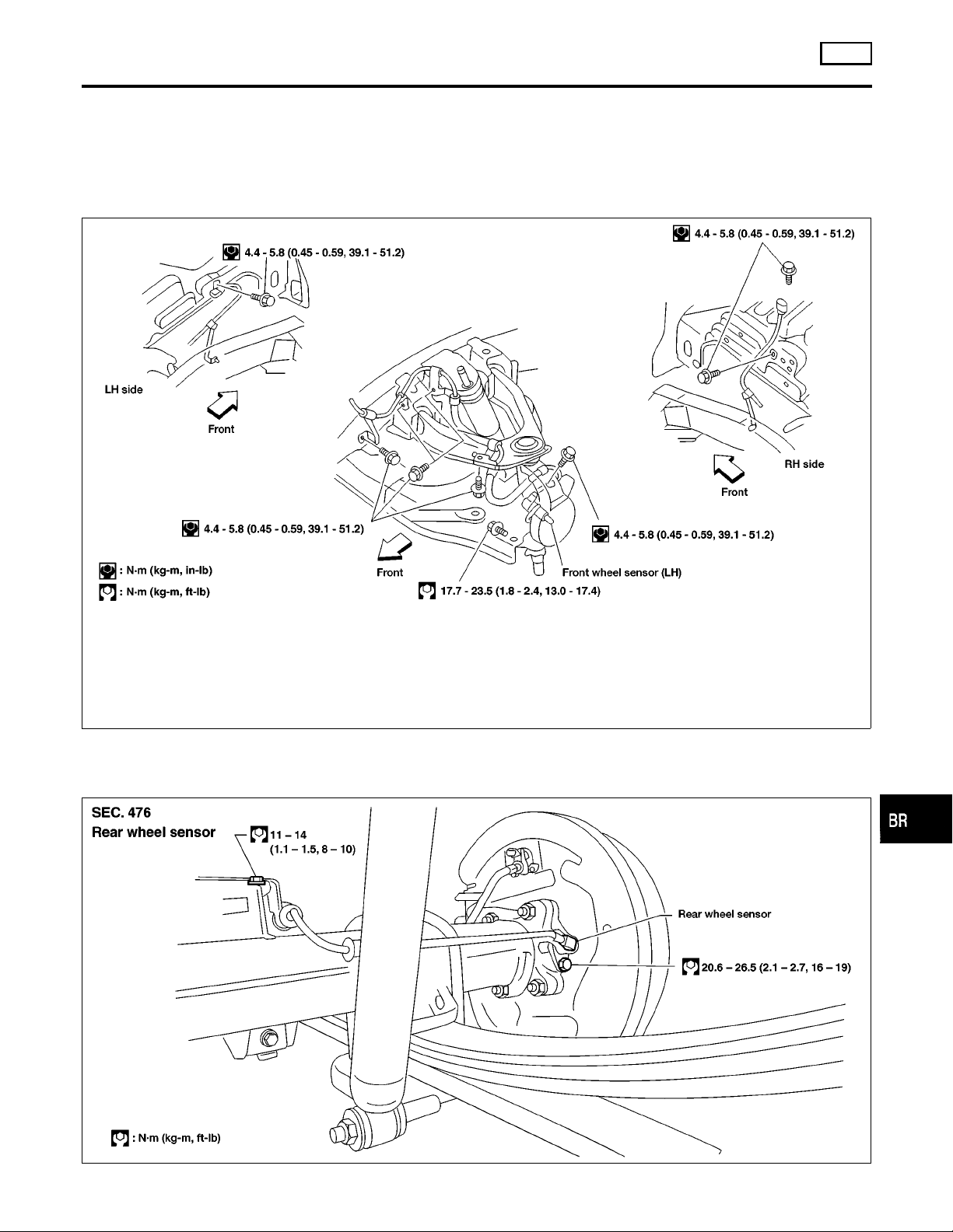
REMOVAL AND INSTALLATION
CAUTION:
Be careful not to damage sensor edge and sensor rotor teeth.
When removing the front or rear wheel hub assembly, disconnect the ABS wheel sensor from the assembly and move it
away.
Front Wheel Sensor
NGBR0079
ABS
Front Wheel Sensor
GI
MA
NGBR0079S01
EM
LC
EC
FE
CL
Rear Wheel Sensor
4WD MODELS
ABR869
NGBR0079S02
NGBR0079S0201
MT
AT
TF
PD
AX
SU
ST
RS
BR-69
BT
HA
SC
EL
ABR868
IDX
Page 70
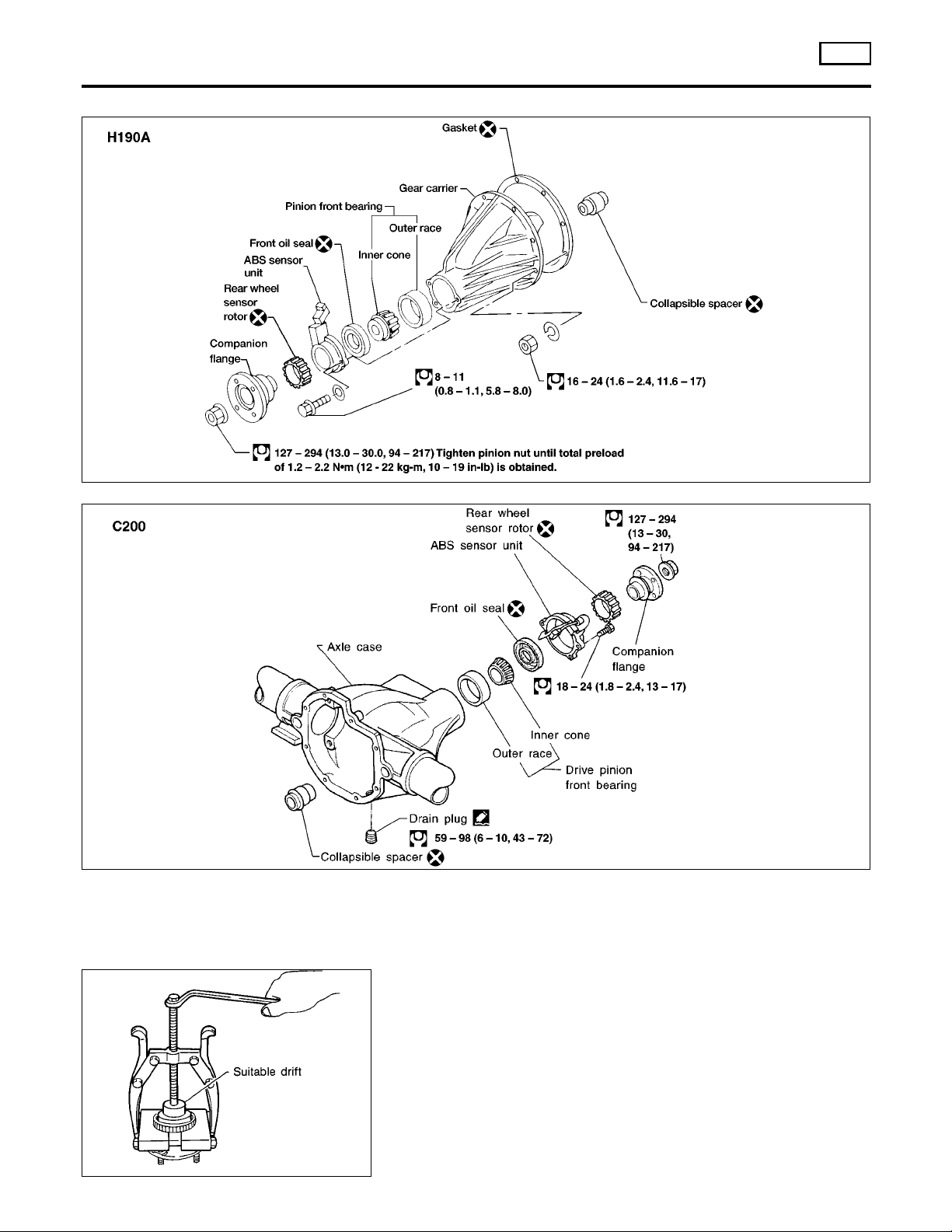
Rear Wheel Sensor (Cont’d)
REMOVAL AND INSTALLATION
ABS
2WD MODELS
=NGBR0079S0202
ABR848
SBR873C
ABR849
Front Sensor Rotor
REMOVAL
1.Removethefrontwheelhub.Referto
AX-11
(“FRONTAXLE”).
NGBR0079S03
NGBR0079S0301
2. Remove the sensor rotor using suitable puller, drift and bearing replacer.
BR-70
Page 71
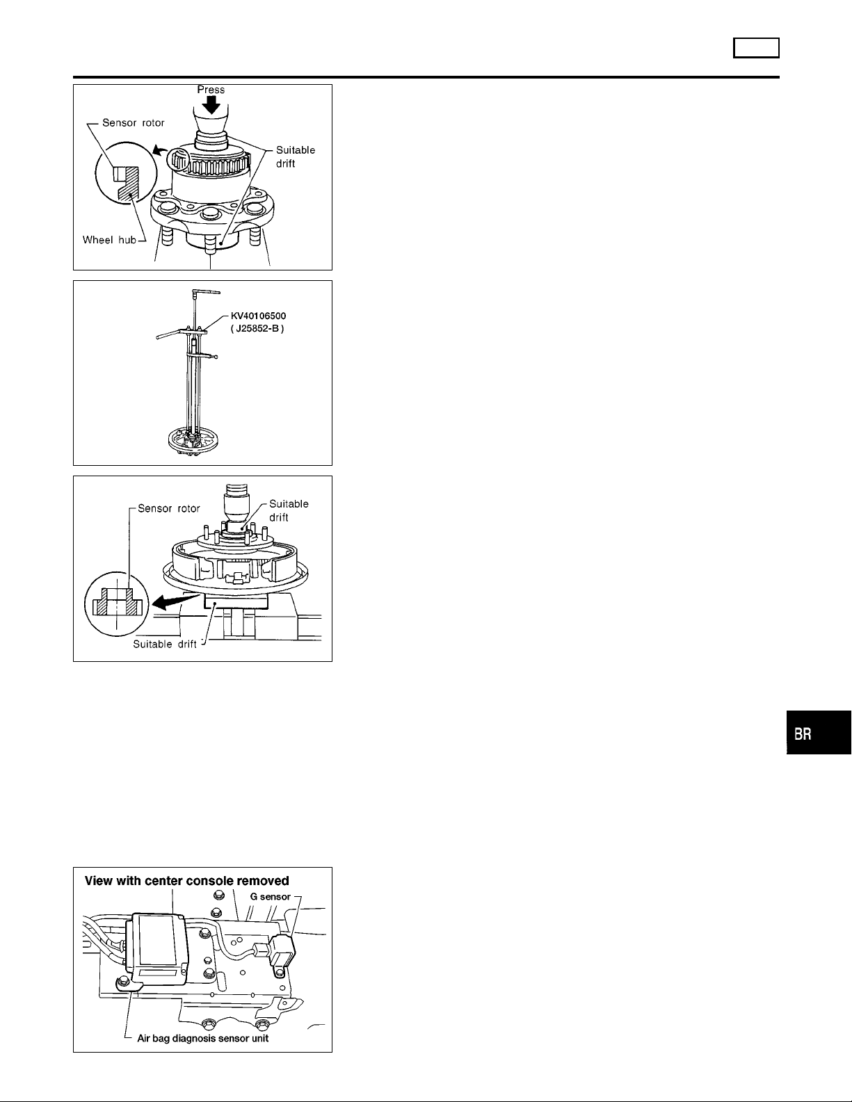
REMOVAL AND INSTALLATION
ABS
Front Sensor Rotor (Cont’d)
SBR400DA
ARA097
INSTALLATION
Install the sensor rotor using suitable drift and press.
I Always replace sensor rotor with new one.
I Pay attention to the direction of front sensor rotor as shown in
figure.
Rear Sensor Rotor (4WD)
REMOVAL
I Remove the sensor rotor using Tool.
INSTALLATION
Install the sensor rotor using suitable drift and press.
I Always replace sensor rotor with new one.
I Pay attention to the direction of front sensor rotor as shown in
figure.
NGBR0079S0302
NGBR0079S04
NGBR0079S0401
NGBR0079S0402
GI
MA
EM
LC
EC
FE
CL
MT
AT
TF
SBR402D
Rear Sensor Rotor (2WD)
REMOVAL AND INSTALLATION
CAUTION:
Be careful not to damage sensor edge and sensor rotor teeth.
In case the final drive assembly needs to be removed, disconnect the ABS sensor from the final drive assembly and move
it away. Failure to do so may result in damage to the sensor
wires making the sensor inoperative.
For final drive models using collapsible spacer (H190A, C200),
bearing preload must be adjusted whenever companion flange
is removed. Therefore, final drive overhaul is required.
G Sensor
Always replace G sensor if bumped or dropped. Otherwise,
performance characteristics of G sensor will be changed,
which in turn changes ABS control performance
characteristics.
NGBR0079S08
NGBR0079S0801
NGBR0079S06
PD
AX
SU
ST
RS
BT
HA
SC
ABR859
EL
IDX
BR-71
Page 72
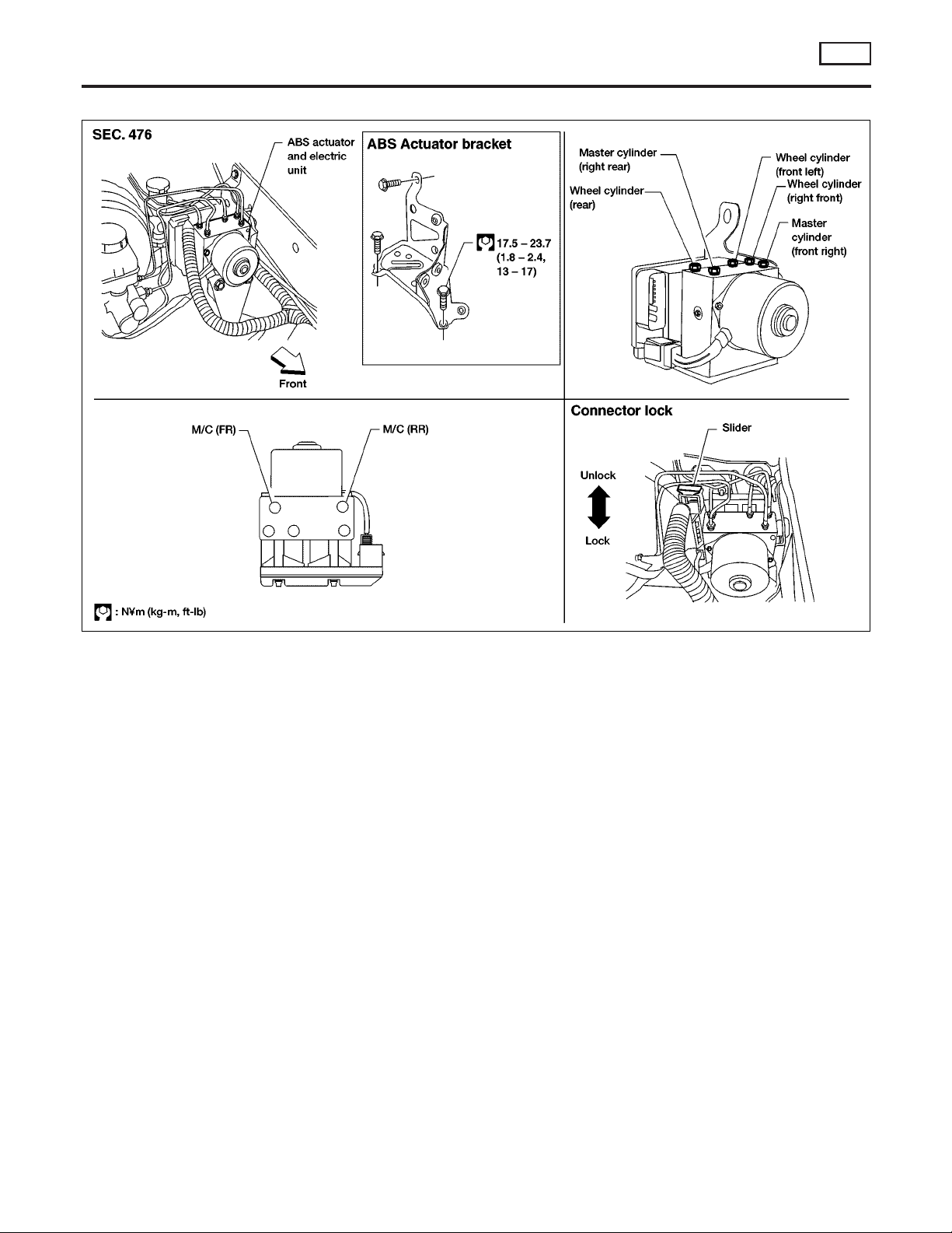
ABS Actuator and Electric Unit
REMOVAL AND INSTALLATION
ABS
ABS Actuator and Electric Unit
=NGBR0079S07
ABR862
REMOVAL
NGBR0079S0701
1. Disconnect battery cable.
2. Drain brake fluid. Refer to “Changing Brake Fluid”, BR-6.
3. Remove mounting bracket fixing bolts and nuts.
4. Disconnect connector, brake pipes and remove fixing nuts and
actuator ground cable.
INSTALLATION
NGBR0079S0702
CAUTION:
After installation, refill brake fluid. Then bleed air. Refer to
“Bleeding Brake System”, BR-8.
1. Tighten actuator ground cable.
Place ground cable at a notch of mounting bracket.
2. Connect brake pipes temporarily.
3. Tighten fixing bolts and nuts.
4. Tighten brake pipes.
5. Connect connector and battery cable.
BR-72
Page 73
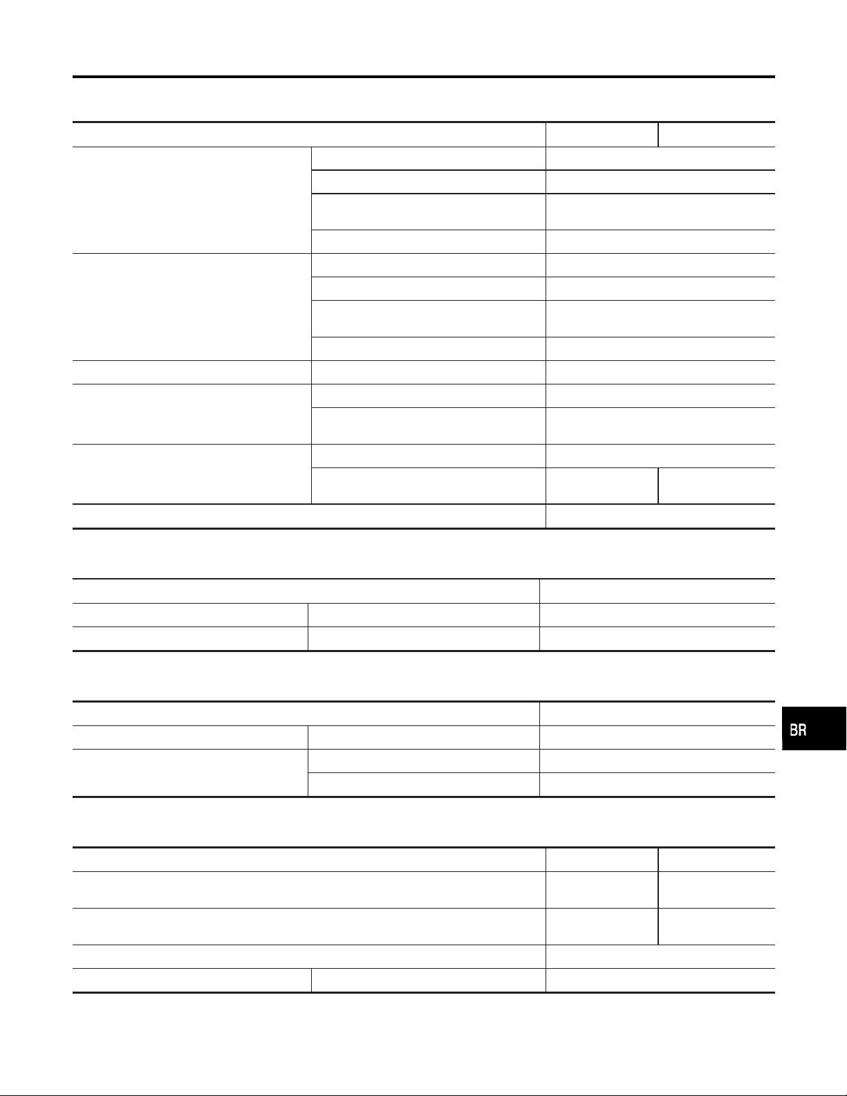
SERVICE DATA AND SPECIFICATIONS (SDS)
General Specifications
General Specifications
Unit: mm (in)
Applied model KA24DE VG33E
Brake model CL33VD
Cylinder bore diameter × number of pistons 46.4 (1.827) × 2
Front brake
Rear brake
Master cylinder Bore diameter 25.40 (1)
Control valve
Brake booster
Recommended brake fluid DOT 3
Pad
Length × width × thickness
Rotor outer diameter × thickness 283 x 28(11.14 × 1.10)
Brake model LT30A
Cylinder bore diameter 22.23 (7/8)
Lining length × width × thickness
Drum inner diameter 295.0 (11.61)
Valve model Proportioning valve within master cylinder
Split point
kPa (kg/cm
Booster model M215T
Diaphragm diameter
2
, psi) × reducing ratio
Pri: 230 (9.06)
Sec: 205 (8.07)
132.0 × 52.5 × 11
(5.20 × 2.067 × 0.43)
296 × 50 × 5.8
(11.65 × 1.97 × 0.228)
2,942 (30, 427) × 0.2
Pri: 230 (9.06)
Sec: 230 (9.06)
NGBR0080
GI
MA
EM
LC
EC
FE
CL
MT
AT
Disc Brake
Unit: mm (in)
Brake model CL33VD
Pad wear limit Minimum thickness 2.0 (0.079)
Rotor repair limit Minimum thickness 26.0 (1.024)
Drum Brake
Unit: mm (in)
Brake model LT30A
Lining wear limit Minimum thickness 1.5 (0.059)
Drum repair limit
Maximum inner diameter 296.5 (11.67)
Out-of-round limit 0.03 (0.0012)
Brake Pedal
Unit: mm (in)
Transmission M/T A/T
Free height “H”*
Depressed height “D”
[under force of 490 N (50 kg, 110 lb) with engine running]
Clearance “C” between pedal stopper and threaded end of stop lamp switch or ASCD switch 0.3 - 1.0 (0.012 - 0.039)
Pedal free play At pedal pad 1 - 3 (0.04 - 0.12)
191 - 201
(7.52 - 7.91)
100 (3.94) 110 (4.33)
201-211
(7.91 - 8.31)
NGBR0081
NGBR0082
NGBR0083
TF
PD
AX
SU
ST
RS
BT
HA
SC
*: Measured from surface of dash lower panel to pedal pad
EL
IDX
BR-73
Page 74

Parking Brake Control
SERVICE DATA AND SPECIFICATIONS (SDS)
Parking Brake Control
Control Type STICK
Lever stroke
[under force of 196 N (20 kg, 44 lb)]
Lever stroke when warning switch comes on 1
10-12
NGBR0084
Unit: notch
BR-74
 Loading...