

Page 1
PagePro 1100
User’s Manual
Page 2

As an ENERGY STAR® Partner, we determined that this machine meets the
TAR® Guidelines for energy efficiency.
S
NERGY
E
What is an ENERGY STAR® product?
NERGY STAR® product has a special feature that allows it to auto-
E
matically switch to a “lo w-po we r mode” aft er a period o f inac ti vity. An
NERGY STAR® product us es energy more efficiently, saves you
E
money on utility bills and helps protect the environment.
Page 3

Foreword
Safety Information
Laser Safety
This is a page printer which operates by means of a laser. There is no
possibility of danger from the laser, provided the printer is operated
according to the instructions in this ma nual.
Since radiation emitt ed by the laser is completely confined within protectiv e hous ing, the laser be am canno t escape from the mach ine duri ng
any phase of user operation.
Internal Laser Radiation
Maximum Radiation Power:
0.6 mW at la ser aperture of the print head unit
Wavelength:
770 – 810 nm
This product employs Class IIIb Laser Diode that emits an invisible
laser beam.
Laser Diode and Scan ning Polygon Mirror ar e incorpor ated in t he print
head unit.
The print head unit is not a field service item.
Therefore, the print head unit should not be opened under any circum-
stance.
Laser Safety
This printer is certified as a Class I Laser product under the U.S.
Department of Health and Human Services (DHHS) Radiation Per-
formance Standard according to the Radiation Control for Health and
Safety Act of 1968. This means that the printer does not produce hazardous laser radiation.
i
Page 4
Foreword
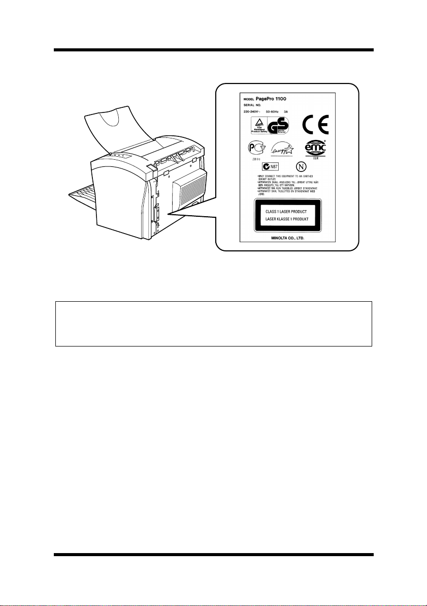
Laser Safety Label
For European Users
Caution
◆ Use of controls, adjustments or performance of procedures other
than those specified in this manual may result in hazardous radiation exposure.
This is a semiconductor laser. The maximum power of the laser diode
is 5 mW and the wavelength is 770 – 810 nm.
ii
Page 5

Foreword
For Denmark Users
ADVARSEL
◆ Usynlig laserstråling ved åbning, når sikkerhedsafbrydere er ude af
funktion. Undgå udsættelse for stråling.
Klasse 1 laser produkt der opfylder IEC60825 sikkerheds kravene.
Dansk: Dette er en hal vlederlas er . Laserd iodens højest e styrke er 5 mW
og bølgelængden er 770 – 810 nm.
For Finland, Sweden Users
LUOKAN 1 LASERLAITE
KLASS 1 LASER APPARAT
VAROITUS!
◆ Laitteen käyttäminen muulla kuin tässä käyttöohjeessa mainit ulla
tavalla saattaa altistaa käyttäjän turvallisuusluokan 1 ylittävälle
näkymättömälle lasersäteilylle.
Tämä on puolijohdelas er. Laserdiodi n suur in teho on 5 mW j a aal lonpituus on 770 – 810 nm.
VARNING
◆ Om apparaten används på annat sätt än i denna bruksanvisning spe-
cificerats, kan användaren utsättas för osynlig laserstrålning, som
överskrider gränsen för laserklass 1.
Det här är en halvledarlaser. Den maximala effekten för laserdioden är
5 mW och våglängden är 770 – 810 nm.
VARO
◆ Avattaessa ja suojalukitus ohitettaessa olet alttiina näkymättömälle
lasersäteilylle. Älä katso säteeseen.
VARNING
◆ Osynlig laserstrålning när denna del är öppnad och spärren är
urkopplad. Betrakta ej strålen.
iii
Page 6
Foreword
For Norway Users
ADVARSEL
◆ Dersom apparatet brukes på annen måte enn spesifisert i denne
bruksanvisning, kan brukeren utsettes for unsynlig laserstråling som
overskrider grensen for laser klass 1.
Dette en halvleder laser. Maksimal effekt till laserdiode er 5 mW og
bølgelengde er 770 – 810 nm.
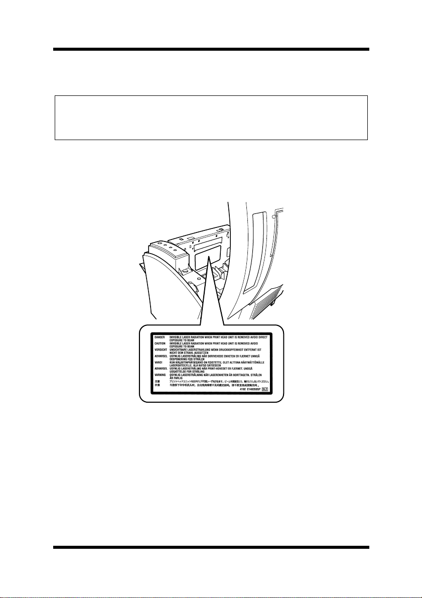
Laser Caution Label
User Instructions
CE Marking (Declaration of Conformity)
We declare u nder our sole re sponsibilit y that the printe r and options to
which this declaration relates are in conformity with the specifications
below.
This declaration is valid for the area of the European Unio n (EU) only.
iv
Page 7

Product Type Laser Beam Printer
Product Name PagePro 1100
Options Second Paper Cassette Unit (4148-601)
Face-Up Tray (4121-0633)
Network Interface Card (4625-131)
Expansion Memory (DIMM)
Foreword
Standard
Safety: EN60 950/1992 with Amendments 1, 2, 3 and 4
Safety o f i nformation tech no lo gy equipment , i n cl ud in g e l ect ri cal business
equipment
EN60825-1/1994 with Amen dment A11
Radiation safety of laser products, equipment classification, requirements
and user’s guide
EMC: EN55 022 (
Limits and method for measurement of radio disturbance characteristic of
information technology equipment (ITE)
EN55024/1998
Information technology equipment – immunity characteristics – Limits and
methods of measurement
EN61000–4–2/1995
Electromagnetic compatibility (EMC)
Part 4: Testing and measurement techniques
Section 2: Electrostatic discharge immunity test
EN61000–4–3/1996
Electromagnetic compatibility (EMC)
Part 4: Testing and measurement techniques
Section 3: Radiated, radio-frequenc y electromagnetic field immunity test
EN61000–4–4/1995
Electromagnetic compatibility (EMC)
Part 4: Testing and measurement techniques
Section 4: Electrical fast transient/burst immunity test
EN61000–4–5/1995
Electromagnetic compatibility (EMC)
Part 4: Testing and measurement techniques
Section 5: Surge immunity test
EN61000–4–6/1996
Electromagnetic compatibility (EMC)
Part 4: Testing and measurement techniques
Section 6: Conducted disturbances inducted by radio-frequency fields –
Immunity test
EN61000–4–8/1993
Electromagnetic compatibility (EMC)
Part 4: Testing and measurement techniques
Section 8: Power-frequency magnetic field immunity test
EN61000–4–11/1994
Electromagnetic compatibility (EMC)
Part 4: Testing and measurement techniques
Section 11: Voltage dips, short interruptions and voltage variations immunity test
Class B
)/1998
EC Directive Safety: 73/23/EEC
EMC: 89/336/EEC and 93/68/EEC
v
Page 8

Foreword
This device must be used with shielded inte rface (Parallel) cable and
shielded network (10/100Base-T) cable.
The use of non-shielded cable is likely to result in interference with
radio communications and is prohibited under 89/336/EEC rules.
Ozone Release
During printer operation, a small quantity of ozone is released. This
amount is not large enough to harm anyone adversely. However, be
sure the room where the m achine is being used has ad equate ventilation, especially if you are printing a high volume of materials, or if the
machine is being used continuously over a long period.
vi
Page 9

Foreword
Welcome
And thank you for selecting a Minolta/QMS PagePro 1100 Printer!
This User’s Manual explains the functions of the printer and how it
operates. It also provides you with troubleshooting tips as well as general precautions you should observe when operating the printer. To
ensure the top performance and effective use of your printer, read this
manual carefully from cover to cover, and keep it at hand for later reference.
No part of this document may be reproduced, transmitted, transcribed,
stored in a re trieval system, or tran slated into other languages without
the express written prior consent of Minolta Co., Ltd..
The contents of this manual are subject to change without notice.
Should there be any di scr epa ncy between the printed material s and the
electronic-based resources provided with your printer, please refer to
the printed materials as your primary resource.
Trademark Acknowledgments
PCL is a registered trademark of Hewlett-Packard Company.
Centronics is a registered trademark of Centronics Inc.
MS-DOS, Microsoft, Windows, and Windows NT are registered trade-
marks of Microsoft Corporation.
IBM is a registered trademark of International Business Machines Cor-
poration.
PagePro is a trademark of Minolta in Europe, Japan and Asia.
Fine-ART and Fine Micro Toning are trademarks of Minolta Co., Ltd.
QMS and the QMS logo are registered trademarks of QMS, Inc.
All other brand or product names are trademarks or registered trade-
marks of their respective companies or organizations.
vii
Page 10

Contents
Chapter 1: Introduction
Features............................................................1-1
Hardware......................................................1-1
Software.......................................................1-1
Operating System........................................1-1
Printer Parts and Accessories. ...................... 1-2
Printer........................................................... 1-2
Options.........................................................1-4
Control Panel ...................................................1-5
Indicators......................................................1-5
Panel Button.................................................1-6
CONTENTS
Chapter 2: Setting-Up
Installation Precautions..................................2-1
Selecting a Location for the Printer.............. 2-1
Space Requirements....................................2-2
Power Source...............................................2-3
Grounding ....................................................2-4
Operational Precautions.................................2-5
Operating Environment................................2-5
Printer........................................................... 2-5
Printer Supplies............................................2-7
viii
Page 11

Installing........................................................... 2-8
Setting-Up ......................................................2-11
Connecting the Power Cord .......................2-11
Loading Paper............................................2-12
Turning on the Printer.................................2-14
Testing the Printer......................................2-15
Connecting to a Computer.........................2-17
Options...........................................................2-18
Second Paper Cassette Unit......................2-18
Face-Up Tray.............................................. 2-21
Expansion Memory....................................2-23
Network Interface Card..............................2-27
Chapter 3: Using the Printer
Using the Panel Button...................................3-1
Contents
Counter Reset Mode....................................3-1
Job Cancel...................................................3-2
Print Configuration Page............................ ..3-2
Form Feed....................................................3-2
Printing Paper.................................................. 3-3
Type..............................................................3-3
Size..............................................................3-4
Printable Area ................ .... ..........................3-6
Loading Paper..................................................3-7
Loading Paper onto Tray1 ............................3-8
ix
Page 12

Contents
Manual Loading (Manual Feed Tray)..........3-10
Loading Paper onto Tray2 (Option)............ 3-13
Selecting Output Direction (Printed Side
Up or Down)................................................... 3-17
Chapter 4: Printer Driver
Introduction......................................................4-1
System Requirements.....................................4-2
Installing the PagePro 1100 Printer Driver
Under Windows 95/Windows 98/Windows
NT 4.0................................................................ 4-3
To Install the PagePro 1100 Printer Driver
Using the Installer (Auto Run)......................4-4
To Install the PagePro 1100 Printer Driver
Using Plug-and-Play ....................................4-8
To Install the PagePro 1100 Printer Driver
Using the Add Printer Wizard.....................4-10
Installing the PagePro 1100 Printer Driver
Under Windows 3.1 .......................................4-12
To Install the PagePro 1100 Printer
Driver..........................................................4-12
Displaying the PagePro 1100 Printer Driver
Setup Dialog...................................................4-16
To Display the Printer Driver Setup Dialog
Under Windows 95/Windows 98................ 4-16
To Display the Printer Driver Setup Dialog
Under Windows NT 4.0..............................4-18
x
Page 13

Contents
To Display the PagePro 1100 Printer Driver
Setup Dialog Under Window 3.1................4-21
Using the PagePro 1100 Printer Driver
Setup Dialog...................................................4-23
Common Buttons.......................................4-23
Paper..........................................................4-24
Page Layout...............................................4-30
Quality........................................................4-36
Device Option.............................................4-38
Uninstalling the Printer Driver...................... 4-39
To Uninstall the PagePro 1100 Printer Driver
(Windows 95/Windows 98/Windows
NT 4.0).......................................................4-39
To Uninstall the PagePro 1100 Printer Driver
(Windows 3.1)............................................ 4-40
DOS Printing Utilities....................................4-41
Installing DOS Printing Utilities.................. 4-41
Loading and Unloading the Status
Monitor.......................................................4-42
Accessing the Printer Control Panel ..........4-44
Using the Printer Control Panel..................4-45
Printer Control Panel Screens....................4-50
Using the Status Display............................4-58
xi
Page 14

Contents
Chapter 5: Printer Status Monitor and Control Panel
Using the Status Monitor................................5-1
Starting Up the Status Monitor.....................5-1
Using the Status Monitor..............................5-4
Using the Control Panel.................................. 5-6
Starting Up the Control Panel ......................5-6
Using the Control Panel ...............................5-6
Chapter 6: Maintenance
Replacing the Toner Cartridge .......................6-1
To Replace the Toner Cartridge ...................6-1
To Reset the Counter of the Toner
Cartridge ......................................................6-6
Replacing the Drum Cartridge .......................6-7
To Replace the Drum Cartridge ...................6-7
To Reset the Counter of the Drum
Cartridge ....................................................6-14
Cleaning the Printer ............................ ..... .....6-15
Cleaning the Outside of the Printer............6-15
Cleaning the Paper Feed Roller................. 6-16
Chapter 7: Troubleshooting
Clearing a Paper Misfeed................................7-1
Inside the Printer.......................................... 7-1
Face-Down Tray...........................................7-6
Face-Up Tray (option).................................. 7-7
xii
Page 15

Tray1.............................................................7-8
Manual Feed Tray......................................... 7-8
Second Paper Cassette Unit (option)...........7-9
Print Quality Problems..................................7-10
No Output...................................................7-15
Indicator Lights (Printer Messages) ............7-17
Indicator Light Patterns..............................7-17
Chapter 8: Specifications
PagePro 1100 Printer.......................................8-1
Second Paper Cassette Unit (Option)............8-4
Expansion Memory (DIMM: option) ...............8-5
Interface Connector and Cable ...................... 8-6
Appendix A: Glossary
Appendix B: Index
Contents
xiii
Page 16

MEMO
Page 17

1Chapter
Introduction
Chapter 1Introduction
1
Page 18

Chapter 1Introduction
Page 19

Features
Features
Hardware
• Compact design
• PCL 6 emulation
• Real 600 dpi resolution
• Prints up to 10 pages per minute (A4/Letter-size print)
• Compact, easy to install toner and drum cartridges
• Fine Micro Toning cartridges for clearer and sharper images
• Fine-ART technology for resolution that actually exceeds 600 dpi
• High speed performance
Software
• Easy to use networking
• Special features like watermark printing, image shift and N-up
printing
• Windows printer s ta tus moni tor – Disp lays s imul taneou s prin ter status information as well as reports the progress of the current print
job
Chapter 1Introduction
Operating System
• Windows 95
• Windows 98
• Windows 3.1x
• Windows NT 4.0
• MS-DOS 5.0 or later (except version 7.0)
1-1
Page 20

Chapter 1Introduction
Printer Parts and Accessories
Printer Parts and Accessories
Printer
Top cover
release button
Power switch
Manual feed tray
Control panel
Paper guide
Tray1
(Multipurpose tray)
Face-down tray
Paper support
1-2
Face-up/Face-down
selection switch
Power cord socket
Parallel interface connector
Page 21
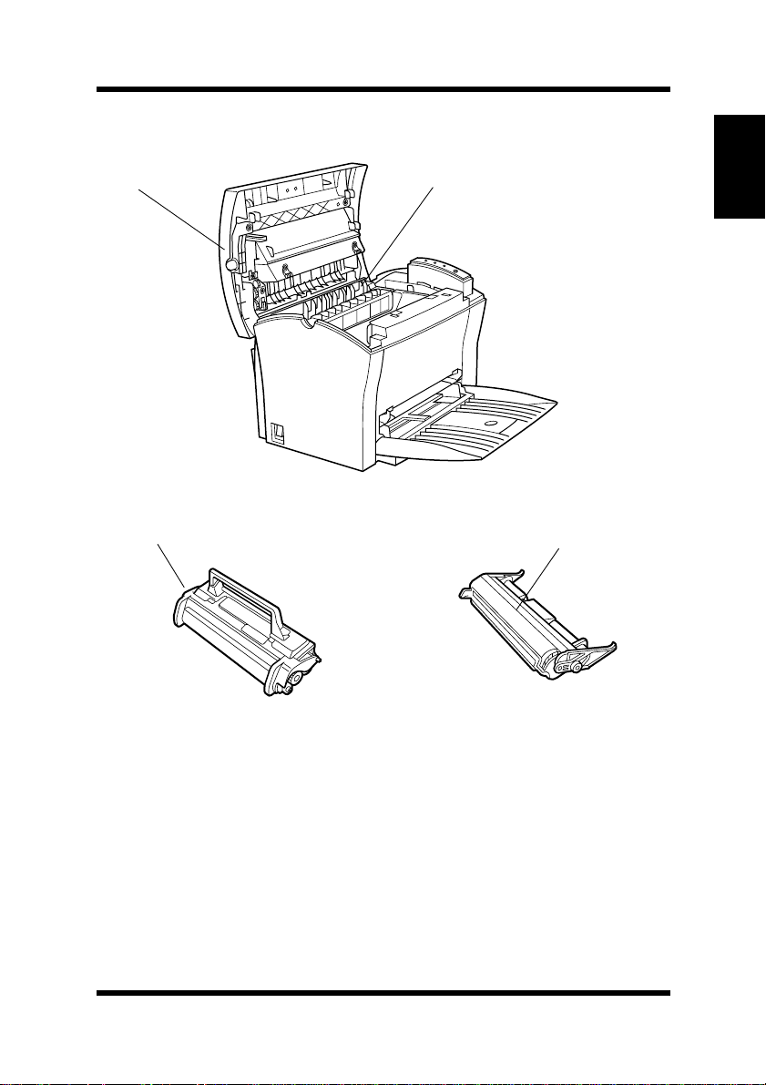
Printer Parts and Accessories
Top cover
Toner cartridge Drum cartridge
Fusing unit
Chapter 1Introduction
1-3
Page 22
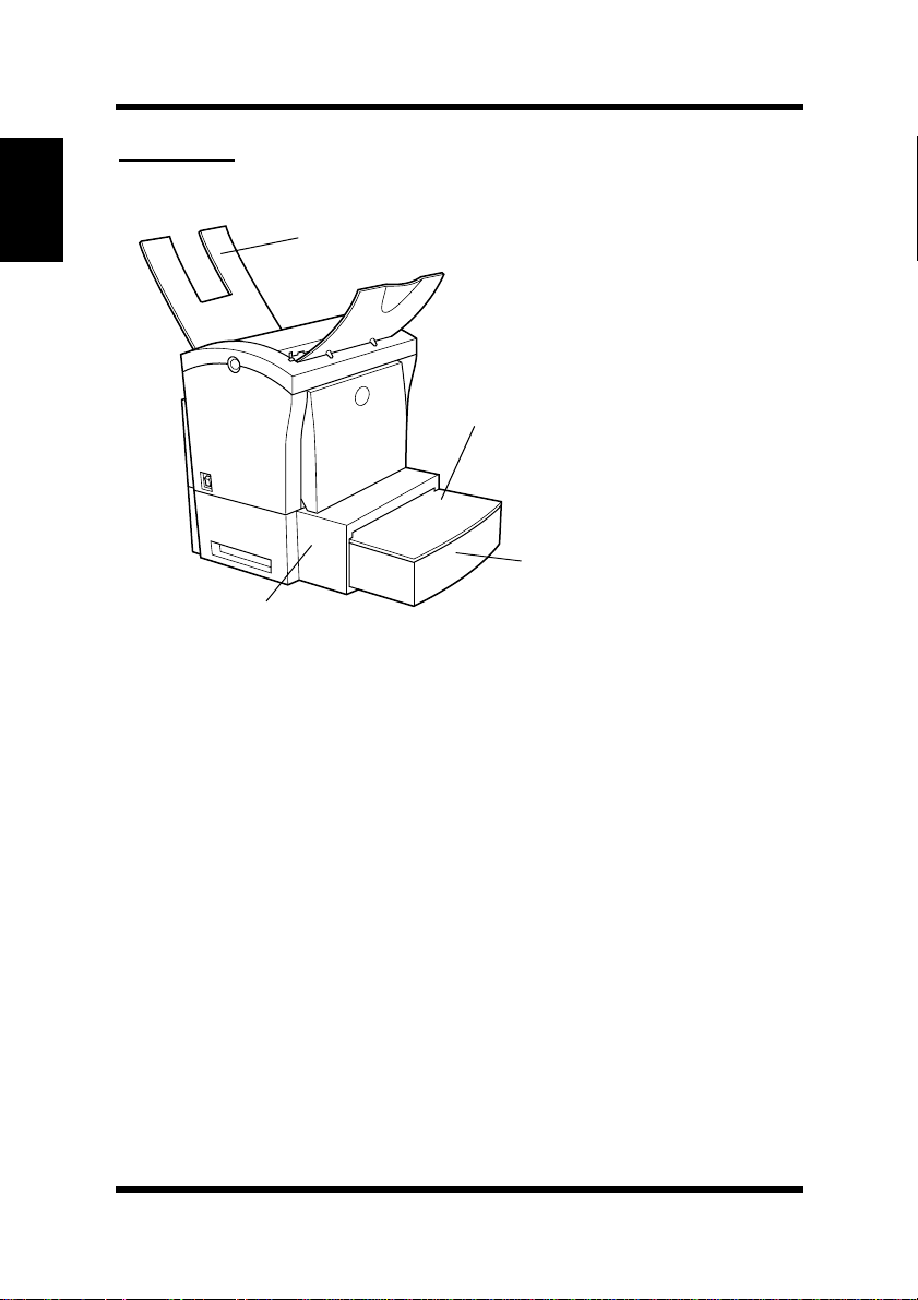
Printer Parts and Accessories
Options
Chapter 1Introduction
Face-up tray
(option)
Cassette cover
Tray2 (500-sheet
second cassette )
Second paper
cassette unit (option)
1-4
Page 23
Control Panel
Control Panel
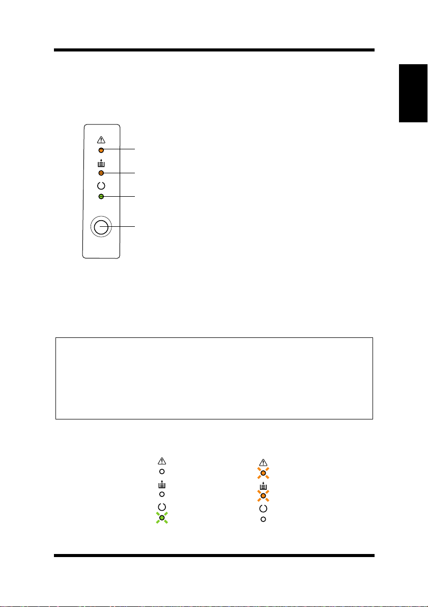
The control panel has three indicators and one button.
Error
(amber) indicator
Paper
(amber) indicator
Ready
(green) indicator
Panel button
Indicators
The three indicators turn on, off, or blink in combination to let you
know the current status of the printer.
Note
Chapter 1Introduction
You can find out details of the printer’s status by checking the informa-
◆
tion that appears on your computer screen (see “Starting Up the Status
Monitor” on page 5-1).
See “Indicator Lights (Printer Messages)” on page 7-17 for information
◆
about how the control panel indicators indicate the current status of the
printer.
ex.)
Printer is ready.
Paper misfeed
1-5
Page 24

Chapter 1Introduction
Control Panel
Panel Button
The panel button can be used to perform various operations according
to the status of the printer.
• Reset the counter
• Job cancel
• Print configuration page
•Form feed
For details, see “Using the Panel Button” on page 3-1.
1-6
Page 25

2Chapter
Setting-Up
Chapter 2Setting-Up
2
Page 26

Chapter 2Setting-Up
Page 27

Installation Precautions
Installation Precautions
Note the follo wing impor tant precaut ions whe n se lect ing a lo catio n for
the printer and when connecting it to a power source.
Selecting a Location for the Printer
A proper location helps to ensure that your printer provides you with
the long service life for which it is designed. Double-check to make
sure that the location you select has the following characteristics.
• Choose a location that is well-ventilated.
• Make sure there is no chance of ammonia or other organic gasses
being generated in the area.
• The power outlet you plan to c onnect to f or power should be nearb y
and unobstructed.
• Make sure that the printer is not exposed to direct sunlight.
• Avoid areas in the direct airflow of air conditioners, heaters, or ventilators, and areas subjected to temperature and humidity extremes.
• Choose a sturdy , level surface where the printer will not be exposed
to strong vibration.
• Keep the printer away from any objects that might block its heat
vents.
• Do not locate the printer near curtains or other combustible objects.
• Choose an area where there is no possibility of the printer being
splashed with water or other liquids.
• Make sure that the surrounding area is clean, dry, and free of dust.
Chapter 2Setting-Up
2-1
Page 28
Installation Precautions
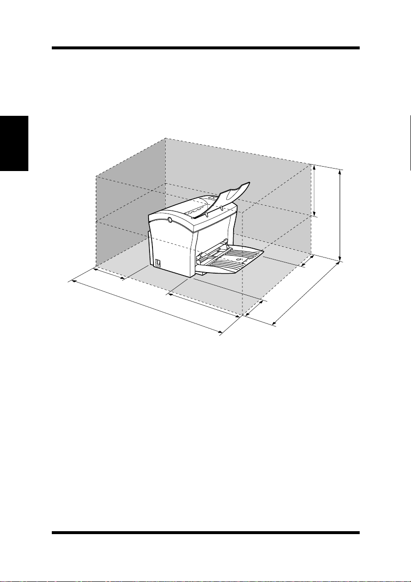
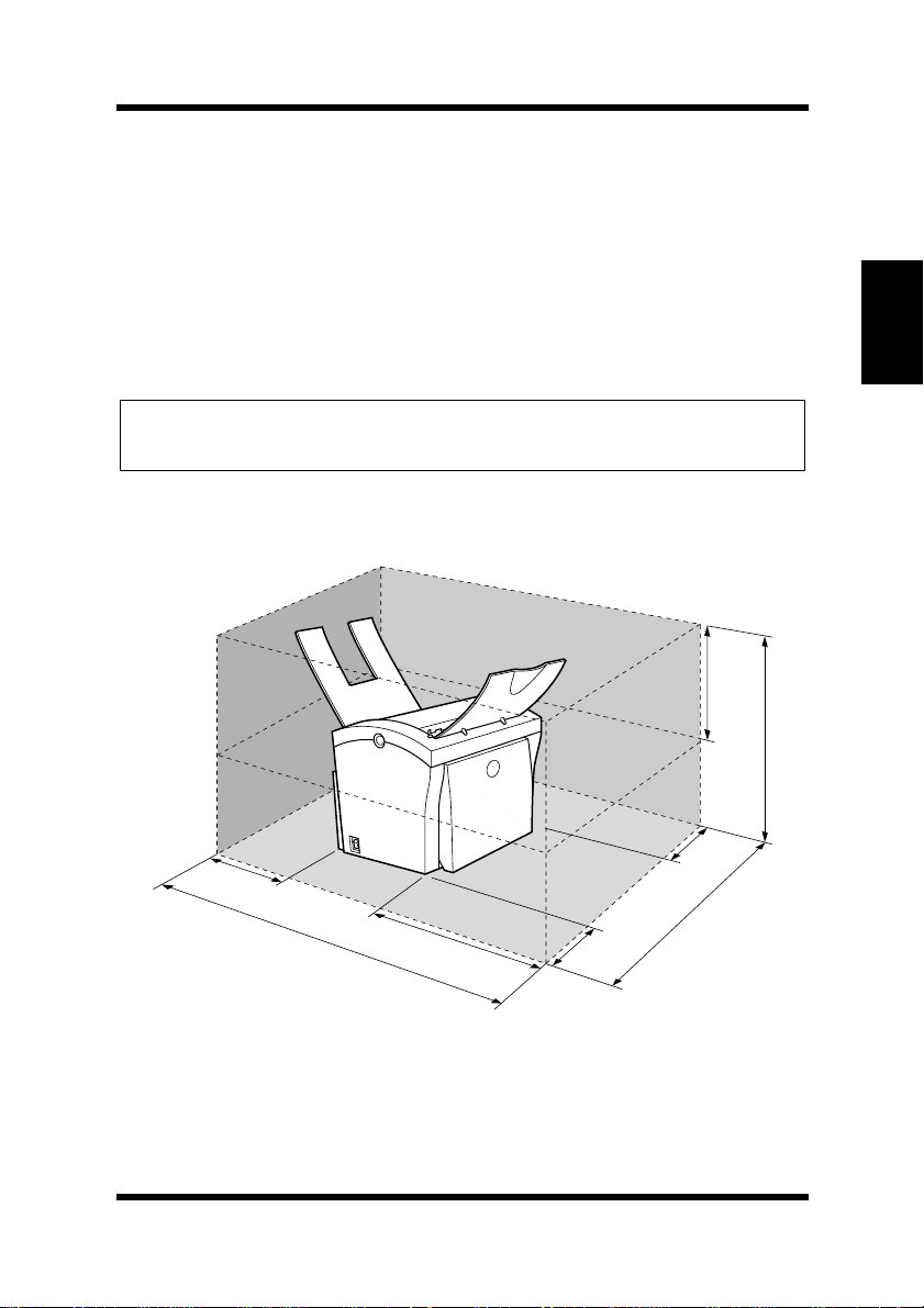
Space Requirements
Be sure to provide space around the printer as indicated below, to
ensure easier printer operat ion , paper and ton er repl acement , and maintenance.
Chapter 2Setting-Up
250 mm
150 mm
(6 in.)
672 mm
(26-1/2 in.)
300 mm
(11-3/4 in.)
200 mm
(7-3/4 in.)
(9-3/4 in.)
507 mm
(20 in.)
100 mm
(4 in.)
680 mm
(26-3/4 in.)
2-2
Page 29

Installation Precautions
Powe r Sourc e
The following are the power source requirements for this printer.
Power supply:
220 – 240 V at 50 – 60 Hz
Voltage fluctuation:
220 – 240 V ±10%
Frequency fluctuation:
Within ±3 Hz
Note
Use a power source with minimal voltage and frequency fluctuation.
◆
Only use an outlet that is rated for the voltage capacity specified for this
◆
printer.
Be sure to plug the power cord all the way into the outlet. The outlet
◆
should be located near the printer and be easily accessible so you can
unplug the powe r cord immediately should any problem occ ur.
Make sure the outlet you use is visible, and not hidden behind the printer
◆
or any other object.
If any other electrical equipment is plugged into the same outlet, make
◆
sure that the capacity of the outlet is not exceeded.
If you use an extension cord, make sure its capacity is greater than the
◆
power consumption of the printer. Using an extension cord with a lower
capacity creates the danger of fire.
Never use a multiple socket to connect other appliances or machines to
◆
the same outlet being used to power the printer.
Chapter 2Setting-Up
2-3
Page 30

Installation Precautions
Grounding
Always ground the printer to guard against the danger of electrical
shock. To ground the printer, con nect th e groundi ng wire t o the grou nd
terminal of the e lectric al outle t you are pl ugging in t o or to a gr ounding
contact that complies with local electrical standards in your area.
Note
Never conn ect t he grounding wire to a gas pipe, the g rou ndi n g wi re f or a
Chapter 2Setting-Up
◆
telephone, or to a water pipe.
2-4
Page 31

Operational Precautions
Operational Precautions
Note the following important precautions whenever using the printer.
Operating Environment
The following describes the operating environment required when
using the pr inter.
Temperature:
10°C to 35°C (50°F to 95°F) with fluctuation of 10°C (18°F) per
hour
Humidity:
15% to 85% with fluctuation of 20% per hour
Printer
The following describes precautions for using the printer.
• Never turn the printer off or open any of its covers during a print
operation.
• Never place flammable gasses , li qui ds or objects that generate magnetic force s near the prin ter.
• When unplugging the power cord, always grasp the plug and never
pull on the cord. A damaged cord creates the danger of fire or electrical shock.
• Never touch the power cor d when your han ds are wet . Doing so creates the danger of electrical shock.
• Always unplug the power cord befo re mo ving t he p rinte r. Failure to
do so can damage the power cord, creating the danger of fire or
electrica l shock.
• Always unplug the power cord if you do not plan to use the printer
for a long time.
• Never try to remove any secured panel or cover. The interior of the
printer contains high-voltage circuitry which creates the danger of
electrical shock when exposed.
Chapter 2Setting-Up
2-5
Page 32

Operational Precautions
• Never try to modify the printer. Doing so creates the danger of fire
or electrical shock.
• Never place any heavy objects on the power cord, pull on it or bend
it. Doing so creates the danger of fire or electrical shock.
• Always make sure the printer is not placed on the electrical cord or
the communications cables of any other electrical equipment. Also
make sure that cords and cables do not get into the printer’s mecha-
Chapter 2Setting-Up
nism. Any of these conditions create the danger of malfunction and
fire.
• Always take care so that paper clips, staples, or other small pieces
of metal do not get into the printer th rough its vents or other openings. Such objects create the danger of fire or electrical shock.
• Do not allow water or other liquids to spill on or near the printer.
Fire or electrical shock can occur should water or liquid come into
contact with the printer.
• Should liquid or any piec e of metal acci dentl y get insi de the print er,
immediately turn it off, unplug the power cord, and contact your
dealer. Failure to take this immediate action creates the danger of
fire or electrical shock.
• Whenever the printer emits unus ually high amount s of hea t, smok e,
an unusual odor, or noise, immediately turn it off, unplug it, and
contact your dealer. F ailure to take this immediate actio n creates the
danger of fire or electrical shock.
Caution
◆ Be sure to locate the printer in a well-ventilated location. A minimal
amount of ozon e is generated during normal operation of this
printer. Because of this, an unpleasant odor may result when the
printer is used for extensive printing in a poorly ventilated area. F or
comfortable, healthy , a nd safe operation, be sure to locate the printer
in a well-ventilated area.
2-6
Page 33

Operational Precautions
Attention
◆ Placer l’imprimante dans une pièce largement ventilée
Une quantité d’ozone négligable est déga gée pendant le fonctionnement de l’imprimante quand celle-ci est utilisée normalement.
Cependant, une odeur désagréable pent être ressentie dans les pièces
dont l’aération est insuffisante et lorsqu’une utilisation prolongée de
l’imprimante est effectuée. Pour avoir la certitude de travailler dans
des conditions de confort, santé et sécurité, il est préférable de bien
aérer la pièce où se trouve l’imprimante.
Printer Supplies
Note the following precautions when handling printer supplies such as
the toner cartridge, the drum cartridge, and paper.
• Avoid storing printer supplies in the following locations.
• Areas subjected to direct sunlight. Additionally, the drum cartridge must be protected from fluorescent light.
• Areas exposed to open flame.
• Areas subjected to high humidity.
• Areas subjected to large amounts of dust.
• Keep paper that has been removed from its wrapper, but not yet
loaded onto the printer tray, in a sealed plastic bag and store it in a
cool, dark location.
• Use only the toner cartri dge that is expressly specified for this
printer.
• Keep supplies out of the reach of children.
• Should your hands become soiled with toner, immediately wash
them with soap and water.
Caution
Chapter 2Setting-Up
◆ Whenever you remove the drum cartridge from the printer, immedi-
ately wrap it with a cloth to protect it against overexposure to light.
2-7
Page 34
Installing
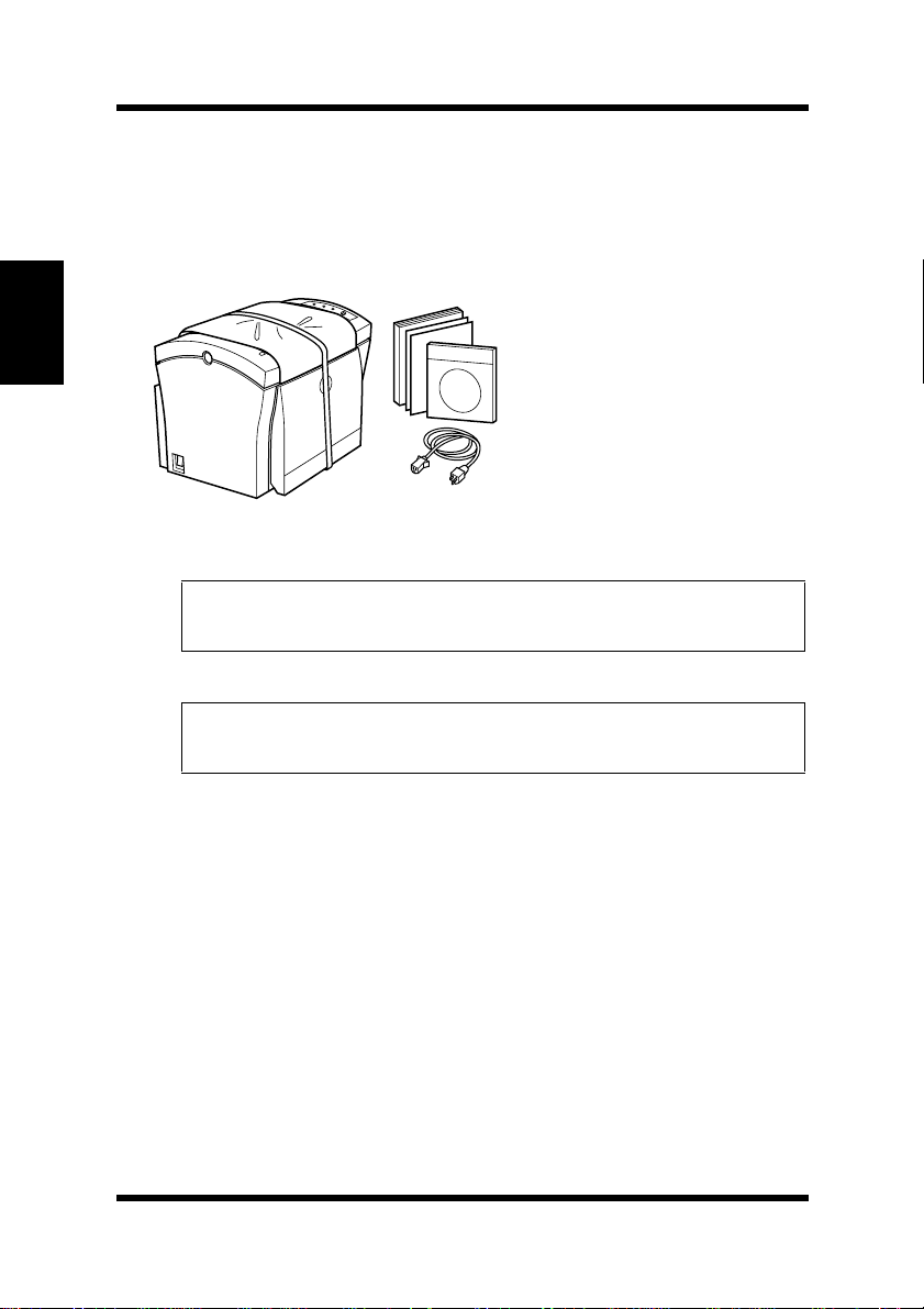
Installing
1
Take the items and accessories shown below out of the carton.
1. Printer
2. Accessories
Chapter 2Setting-Up
Caution
◆ After unpacking, keep all packing materials out of the reach
of children.
Note
Keep all the boxes and packing materials that the printer comes in
◆
for later use when transporting the printer.
User’s Guide
CD-ROM
Power cord
Warranty booklet
Registration card
2-8
Page 35
Installing
2
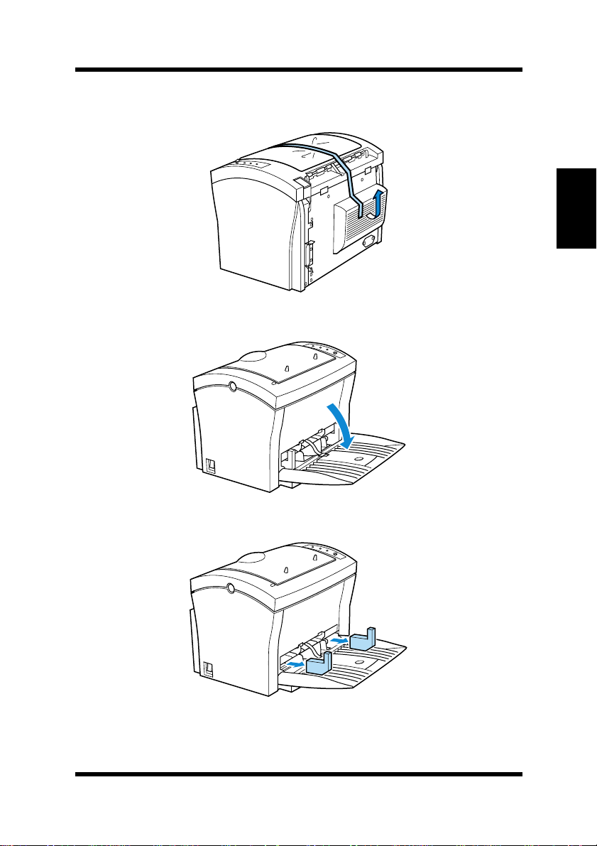
Remove the plastic bag and peel off the shipping tape from the
printer.
3
Pull Tray1 from the printer with both hands and lie it down flat.
Chapter 2Setting-Up
4
Pull out the two cushions from the paper feed inlet.
2-9
Page 36
Installing
5
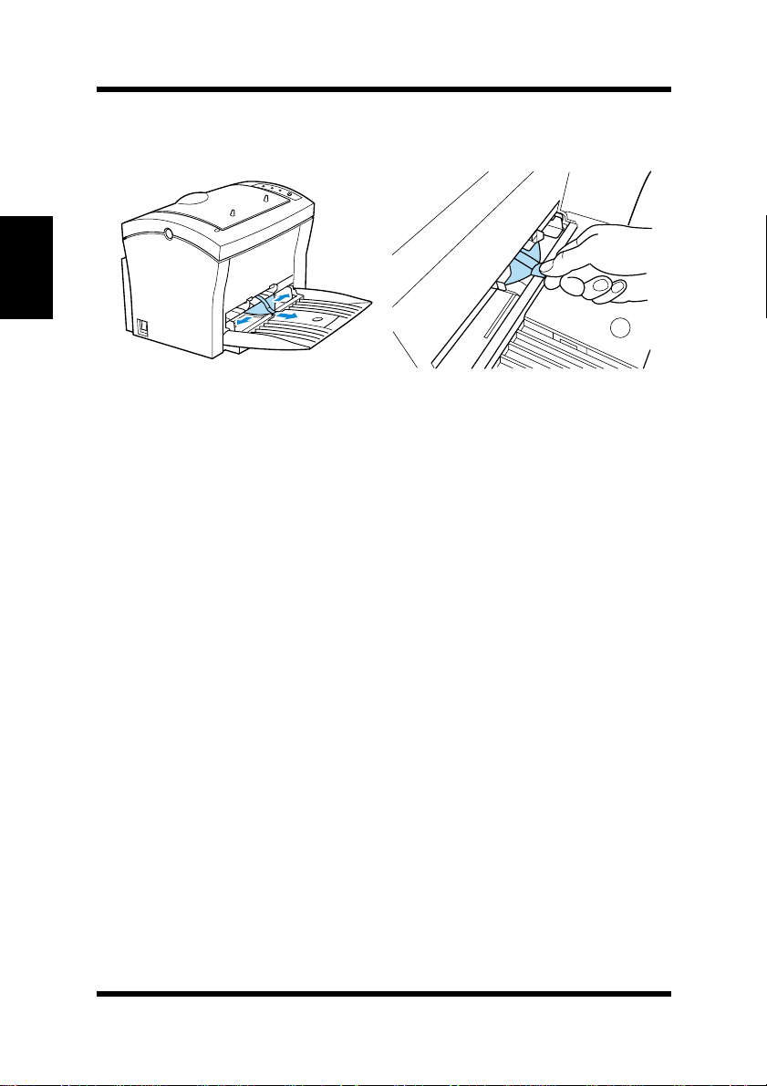
Squeeze the right paper size guide and open the paper size
guides. Pull out the plastic-lead strip from the paper feed inlet.
Chapter 2Setting-Up
For instructions on installing the optional item(s), see “Options” on
page 2-18.
2-10
Page 37
Setting-Up
Setting-Up
Set-up the printer according to the following instructions.
For instructions on installing the optional item(s), see “Options” on
page 2-18.
Connecting the Power Cord
1
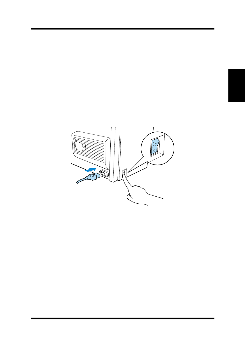
Make sure that th e power switch is in the ❍ (Off) position.
2
Connect one end of the po wer cord tha t comes wi th th e printe r to
the power cord socket. Plug the other end into a power outlet.
2
1
Chapter 2Setting-Up
2-11
Page 38
Setting-Up
Loading Paper
1
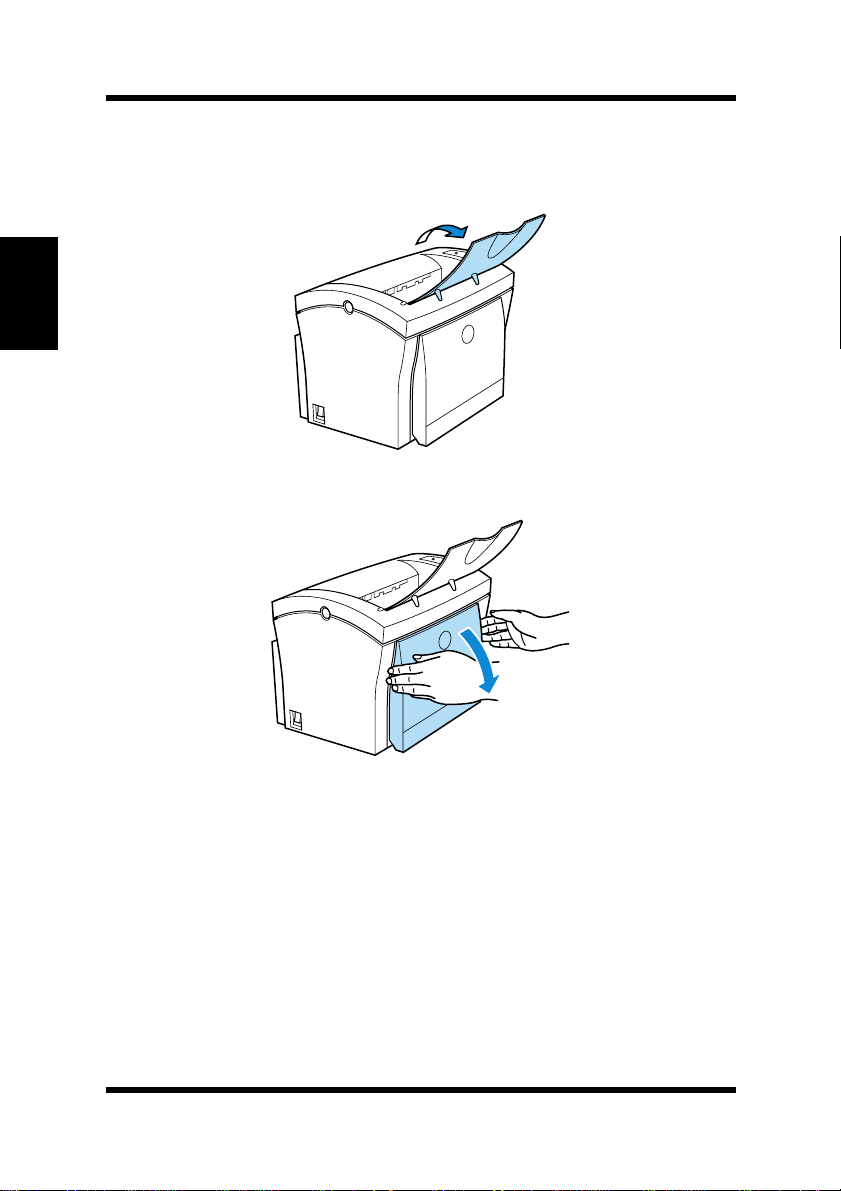
Open the face-down tray .
Chapter 2Setting-Up
2
Pull Tray1 from the printer with both hands and lie it down flat.
2-12
Page 39
Setting-Up
3
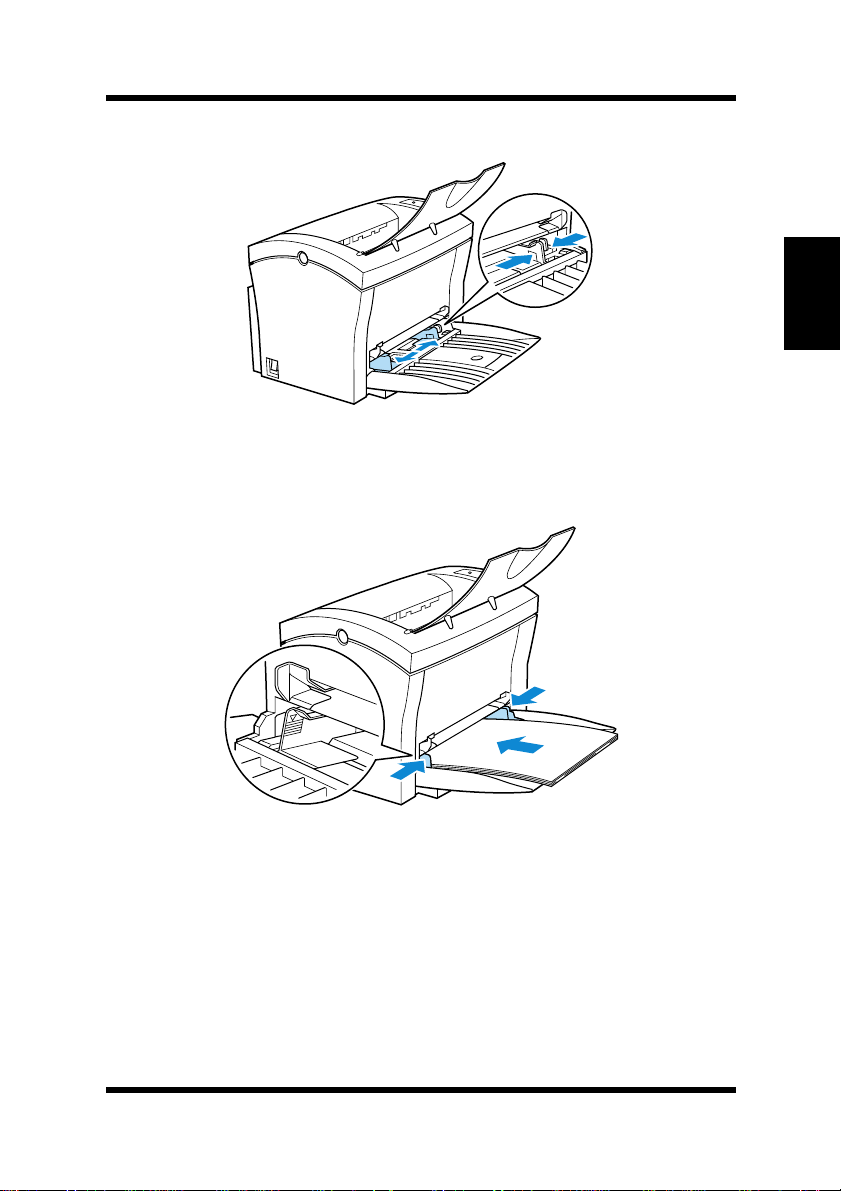
Squeeze the right paper guide and open the paper guides.
4
Place a stack of paper in the center of Tray1. Squeeze the right
paper guide and adjust the paper guides so that both the left and
right sides of the paper stack are secure.
Chapter 2Setting-Up
2-13
Page 40
Setting-Up
Turning on the Printer
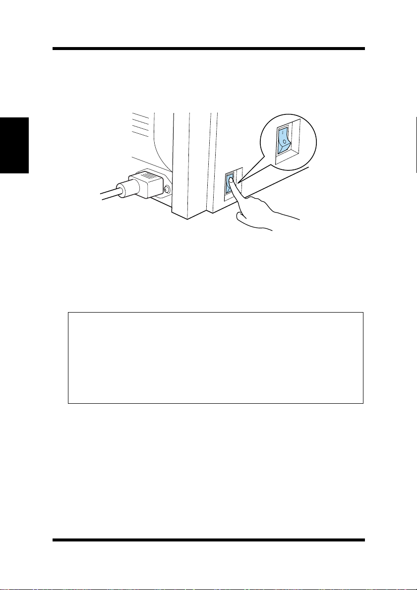
■ After connecting the printer to a power outlet, press the power
switch to turn it on.
Chapter 2Setting-Up
Turning on the printer causes all the indicato rs on the cont rol panel
to light, which indicates that the printer is warming up. In about 23
seconds or less, only t he Ready indicator remains lit, i ndicating tha t
the printer is ready to print.
Note
The printer automatically enters a power saving mode after a set
◆
period of time in which it does not receive a print command from the
computer . The default setting is 1 5 m inut es , h owever, the time period
can be changed using the control panel (see “Using the Control
Panel” on page 5-6). Whenever the printer receives a print command
while in the power saving mode, it will automatically start to warm
up before printing.
2-14
Page 41
Setting-Up
Testing the Printer
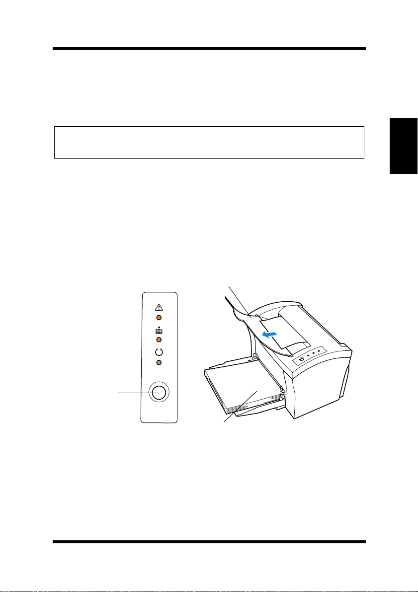
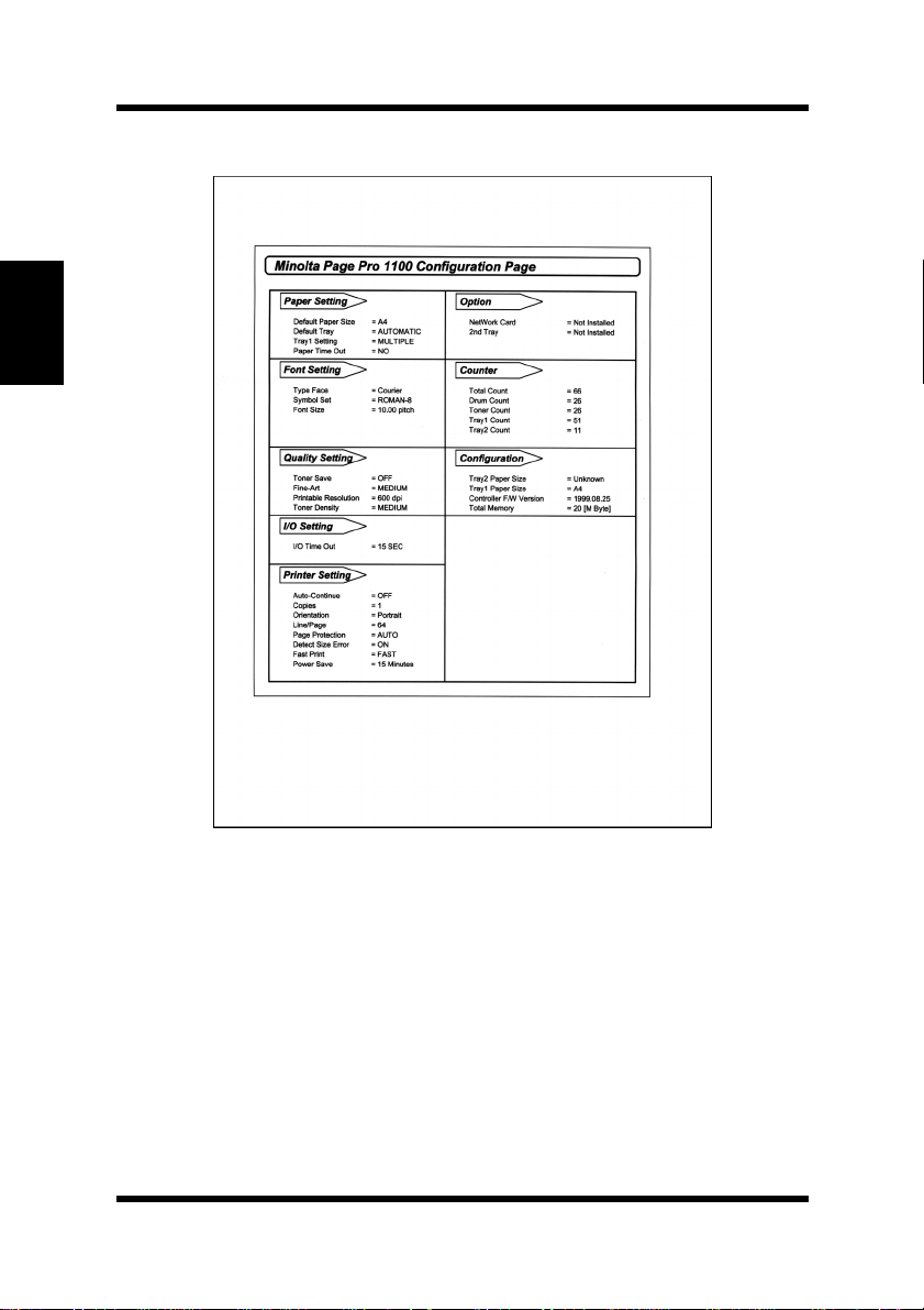
Perform the following procedure to print a configuration page and see
if the printer is working correctly.
Note
See “No Output” on page 7-15 for information on what to do if the con-
◆
figuration page does not prin t when you press t he
1
Place the A4 size paper onto Tray1.
2
Make sure that b oth the Paper and Error in dic at o rs are off, and
the Ready indicator is on. This indicates there is no existing
error condition and no data remaining to be printed.
3
Briefly press the panel button to start the configuration page
print operation.
Face-down tray
panel button
.
Chapter 2Setting-Up
Panel button
Tray1
2-15
Page 42
Setting-Up
Sample Configuration Page
Chapter 2Setting-Up
2-16
Page 43
Setting-Up
Connecting to a Computer
Caution
◆ Always use a shielded interface cable. Use of an unshielded cable can
result in radio interference with data.
Note
You must purchase an IEEE 1284 type-B cable for connection between
◆
the printer and a computer. For detailed specifications of the interface
cable, see “Interface Connector and Cable” on page 8-6.
Minolta does not warrant the use of any particular cable. The user
◆
assumes all responsibility as to the quality and performa nce of the cabl e .
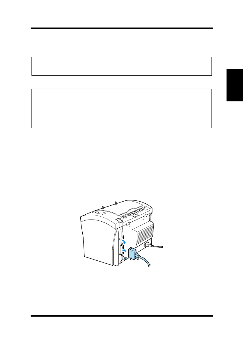
1
Make sure that the printer and the computer you are connecting
it to are both turned off.
2
Connect one end of the interface cable to the parallel port of the
computer.
3
Connect the other end of the interface cable to the parallel interface connector on the back of the printer. Secure the interface
cable using the two clips on the parallel interface connector.
Chapter 2Setting-Up
2-17
Page 44
Options
Options
This section describes the optional items that are available for this
printer.
Second Paper Cassette Unit
The second paper cassette unit comes equipped with a cassette that
Chapter 2Setting-Up
can hold up to 500 sheets of A4 size paper called Tray2.
The same unit can accommodate a variety of other paper trays as well
(Letter, JIS B5, Legal, Executive). Contact your dealer to find out how
you can add these trays to increase the capabilities of your printer.
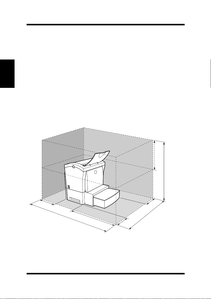
Space Requirements
250 mm
(9-3/4 in.)
2-18
150 mm
(6 in.)
972 mm
(38-1/4 in.)
600 mm
(23-1/2 in.)
200 mm
(7-3/4 in.)
100 mm
(4 in.)
680 mm
(26-3/4 in.)
626 mm
(24-3/4 in.)
Page 45
Installing the Second Paper Cassette Unit
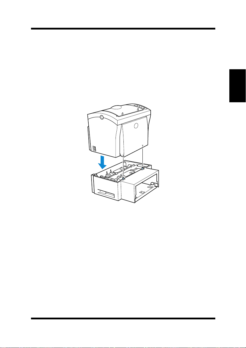
1
Remove the second paper cassette unit and Tray2 fr om their
packaging, includi ng the p rotec ti ve tape used to hold th e v ari ous
components in place.
2
Place the printer on top of the base unit. Make sure to align the
coupling pins of the base unit with the holes located underneath
the printer.
Options
Chapter 2Setting-Up
3
Load paper onto Tray2. See “Loading Paper onto Tray2
(Option)” on page 3-13 for details.
2-19
Page 46
Options
4
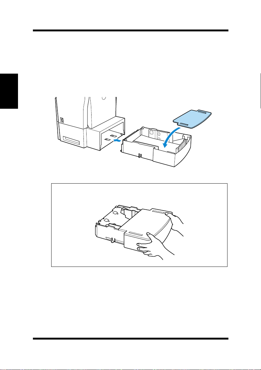
Replace the cassette cover and insert Tray2 into the second
paper cassette unit.
Chapter 2Setting-Up
Note
2-20
Be sure to use both hands whenever
◆
inserted into the
second paper cassette unit
Tray2
is removed from or
.
Page 47
Options
Face-Up Tray
This face-up tray receives printed pages, printed side up, as they are
output from the pr inter. Printed pages are not rolled d uring the pr inte r’s
output sequence when this tray is used. For this reason, the face-up
tray is recommended for thick paper or envel ope s t o avoid curling during the feeding process.
The maximum capacity of the face-up tray is 20 sheets.
Note
For details on changing the output direction, see “Selecting Output
◆
Direction (Printed Si de Up or Down)” on page 3-17.
Space Requirements
300 mm
(11-3/4 in.)
557 mm
(22 in.)
Chapter 2Setting-Up
250 mm
(9-3/4 in.)
772 mm
(30-1/2 in.)
300 mm
(11-3/4 in.)
200 mm
(7-3/4 in.)
100 mm
(4 in.)
680 mm
(26-3/4 in.)
2-21
Page 48
Options
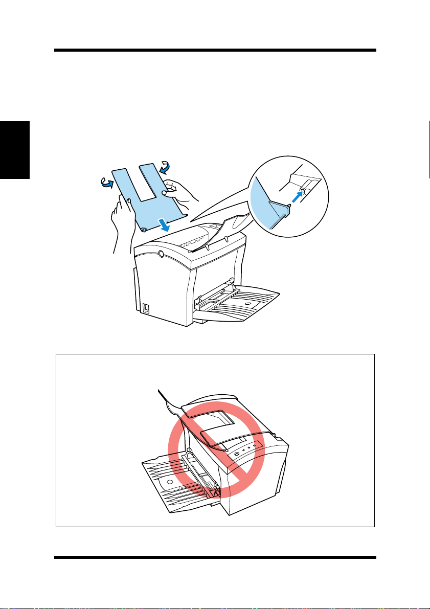
Installing the Face-Up Tray
1
Remove the face-up tray from its carton.
2
Gently bend the output tray inwards, toward the printer, with
both hands. Align the in serti on pins of the tr ay with the pin ho lders of the pr inter.
Chapter 2Setting-Up
Note
Never lay the
◆
excessive to it.
2-22
face-up tray
towards the front of the printer or apply
Page 49

Options
Expansion Memory
You can avoid many errors caused by data overload by installing sufficient memory into the printer.
This printer comes with 4 MB of memory. You c an increase memory
capacity up to 132 MB by installing an optional 16, 32, 64 or 128 MB
expansion memory (DIMM) into the printer.
DIMMs are available from most computer retailers.
Note
Use only PC/100 compliant DIMMs.
◆
Installing the Expansion Memory
Warning
Electric shock hazard! Do not remove any cover of the printer that is
◆
not directly specified for removal in the
1
Turn off the printer and unplug the power cord.
2
Disconnect the printer c able from the printer.
User’s Manual
.
Chapter 2Setting-Up
3
Press the top cover release button and open the top cover.
2-23
Page 50
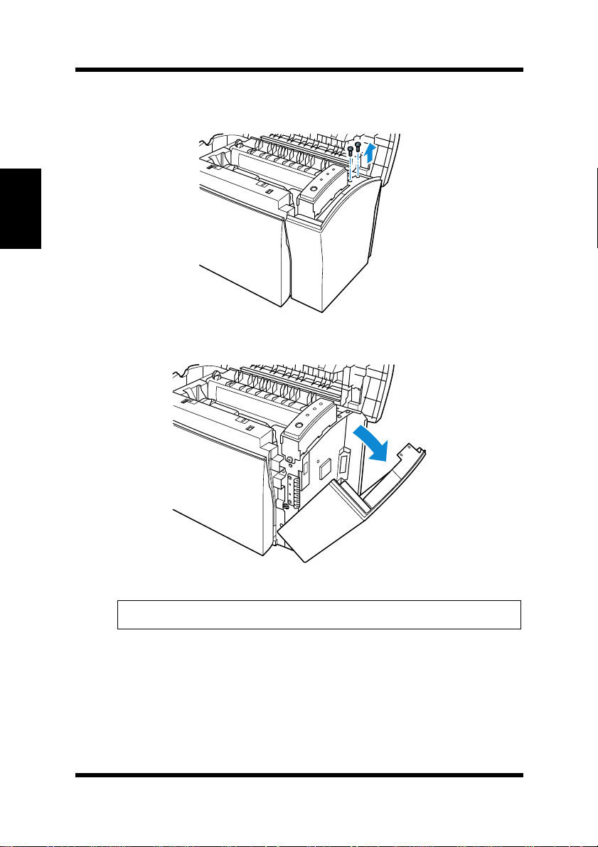
Options
4
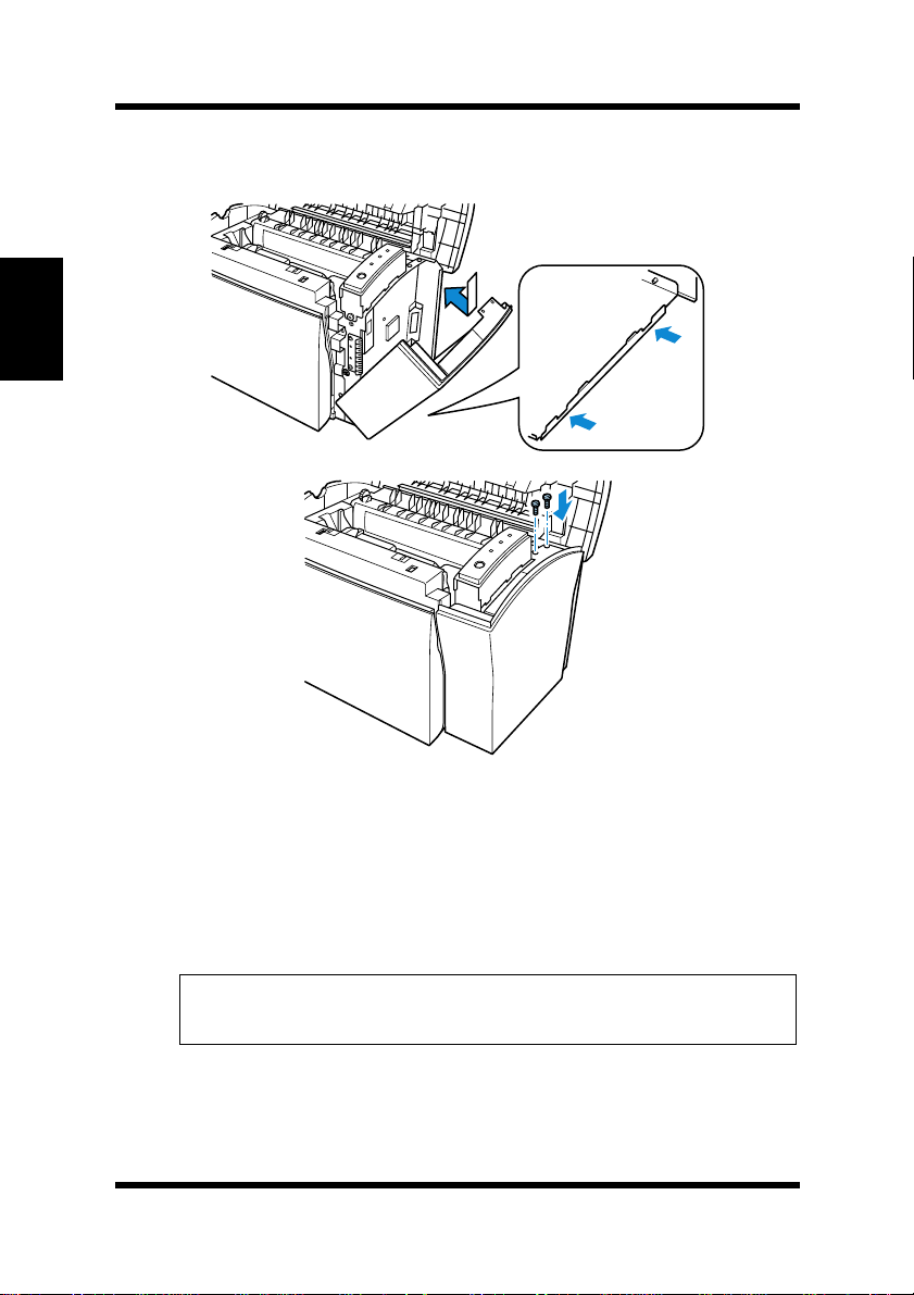
Remove the t wo screws that hold t he side cover of the printer i n
place with a screwdriver.
Chapter 2Setting-Up
5
Remove the si de co v er.
2-24
Caution
Do not touch any part of the main circuit inside the printer.
◆
Page 51
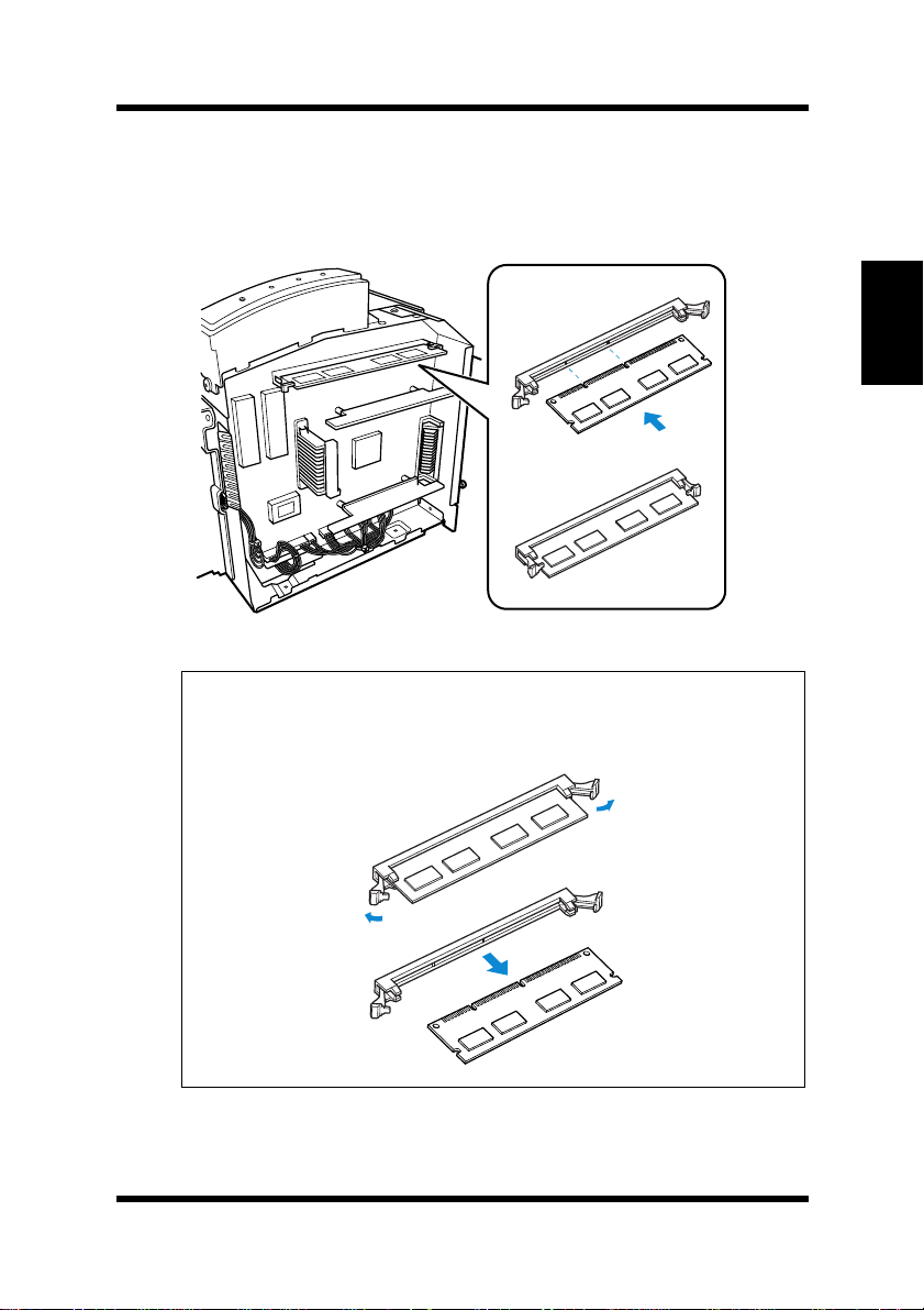
6
Being careful not to touch the connection points along the edge
of the expansion memory, insert the board into the socket on
the main circuit. Apply pressure until the expansion memory
locks into place.
Tip
Options
Chapter 2Setting-Up
To remove the
◆
the taps on each side of the socket to release the
ory
.
expansion memory
from the main circuit, press
expansion mem-
2-25
Page 52
Options
7
Replace the side cover using the two screws provided to secure
it in place.
Chapter 2Setting-Up
8
Print a configuration page “Testing the Printer” on page 2-15
and check to confirm that the “Total Memory” item correctly
shows the increase in memory capacity. If it does not, repeat the
above steps making sure that the expansion memory is installe d
correctly.
Note
Once the
◆
the Printer Memory Setting to reflect the new memory capacity.
expansion memory
has been installed, be sure to reset
2-26
Page 53
Options
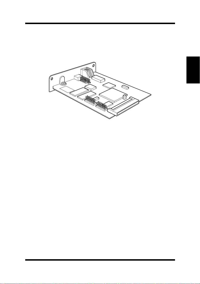
Network Interface Card
The network interface card is equipped with a 10/100BASE-T inter-
face connector for connection to the network server.
Refer to the Network Interface Card User’s Manual for detail.
Chapter 2Setting-Up
2-27
Page 54

MEMO
Chapter 2Setting-Up
Page 55

3Chapter
Using the Printer
Chapter 3Using the Printer
3
Page 56

Chapter 3Using the Printer
Page 57
Using the Panel Button
Using the Panel Button
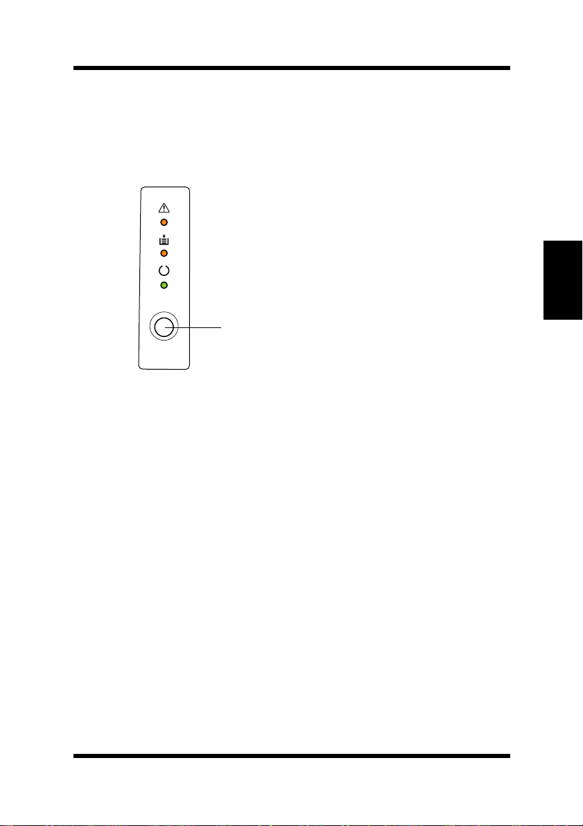
The panel button can be used to perform va rious operat ions accord ing
to the status of the printer.
Panel button
Counter Reset Mode
Use the following procedure whenever you want to reset the counter.
1
Turn off the printer.
Chapter 3Using the Printer
2
While holding down the panel button, turn on the printer.
3
Keep the panel button held down, and t he Ready indicator will
start to blink. After the Ready indicator has blinked for about 5
seconds, release the panel button. This should cause all the
indicators to start to blink.
4
After all the indicators blink, the printer enters the counter reset
mode. See “To Reset the Counter of the Toner Cartridge” on
page 6-6 and “To Reset the Counter of the Drum Cartridge” on
page 6-14 for details.
3-1
Page 58

Using the Panel Button
Job Cancel
Use the following procedure whenever you want to cancel the current
job.
1
Hold down the panel button for more than 5 seconds.
2
After all the in dicat ors ar e lit , re lease th e panel b ut ton to can cel
the print jo b.
Print Configuration Page
Use the following procedure whenever you want to configuration for
Chapter 3Using the Printer
printer.
■ Press the panel button while printer is idle without any errors and
job requests. See “Testing the Printer” on page 2-15 for details.
Form Feed
Use the following procedure to resume pr inting after a n error occurs
dues to any one of the following causes.
• Print job is too complex.
• Memory overflow
• Almost out of paper
• Wrong size paper was fed into the printer.
■ Press the panel button to perform a form feed.
3-2
Page 59
Printing Paper
Printing Paper
Type
Caution
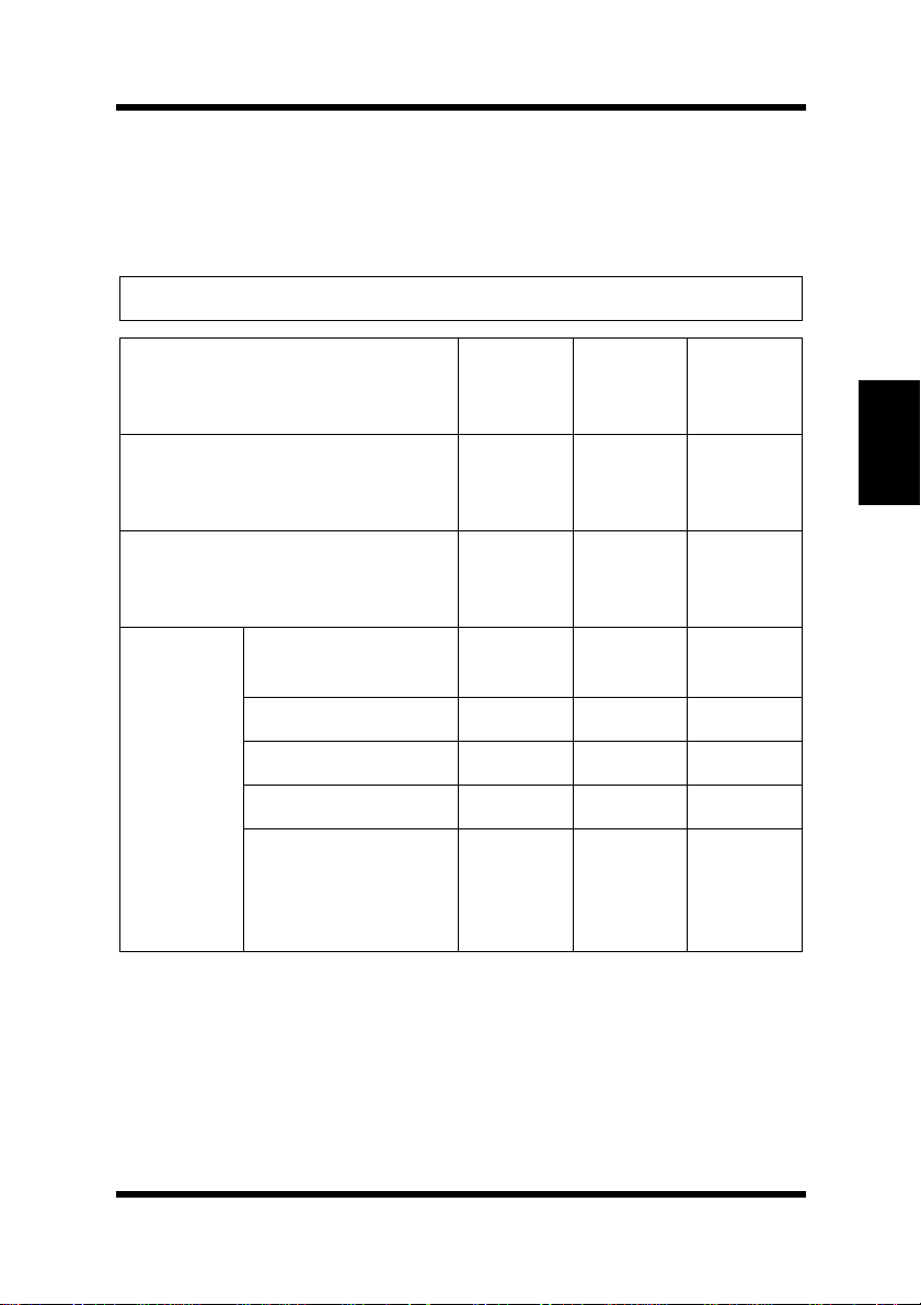
◆ This printer is designed to print on only the following types of pa per.
Paper Source Manual
Paper Type
60 to 90 g/m
Recycled Paper
60 to 90 g/m
Plain Paper
weight:
2
(16 to 24 lbs.)
weight:
2
(16 to 24 lbs.)
Feed
Tray
❍❍❍
❍❍❍
Tray1 Tray2
Chapter 3Using the Printer
Special
Paper
Transparency
Sheet
Labels
Letterhead
Envelopes
Thick Paper
weight:
90 to 163 g/m
(24 to 43-1/4 lbs.)
2
❍❍
❍❍
❍❍
❍❍
❍❍
None
None
None
None
None
3-3
Page 60

Printing Paper
Size
Caution
◆ This printer is designed to print on only the following sizes of paper.
Standard sizes
Paper Source Manual
Feed
Paper Size
A4
Chapter 3Using the Printer
Standard
Size
*1.Each of the 5 cassettes of T ray2 support one of the 5 types of p aper that are
compatible with this printer.
*2.A4 is standard cassette size for the second paper cassette unit.
210 mm × 297 mm
A5
148 mm × 210 mm
JIS B5
182 mm × 257 mm
Legal
8-1/2 in.× 14 in.
Letter
8-1/2 in. × 11 in.
Executive
7-1/4 in. × 10-1/2 in.
Tray
❍❍❍
❍❍
❍❍❍
❍❍❍
❍❍❍
❍❍❍
Tray1 Tray2
*1
*2
None
3-4
Page 61

Envelope and Custom Size
Paper Source Manual
Paper Size
Feed
Tray
Printing Paper
Tray1 Tray2
Envelope
and Cus-
tom Size
Env. DL
110 mm × 220 mm
Env. C5
162 mm × 229 mm
Env. B5
176 mm × 250 mm
Env. Com10
4-1/8 in. × 9-1/2 in.
Env. Monarch
3-7/8 in. × 7-1/2 in.
Custom Size
76 mm to 216 mm
(3 in. to 8-1/2 in.) ×
127 mm to 356 mm
(5 in. to 14 in.)
❍❍None
❍❍None
❍❍None
Chapter 3Using the Printer
❍❍None
❍❍None
❍❍None
3-5
Page 62
Printing Paper
Printable Are a
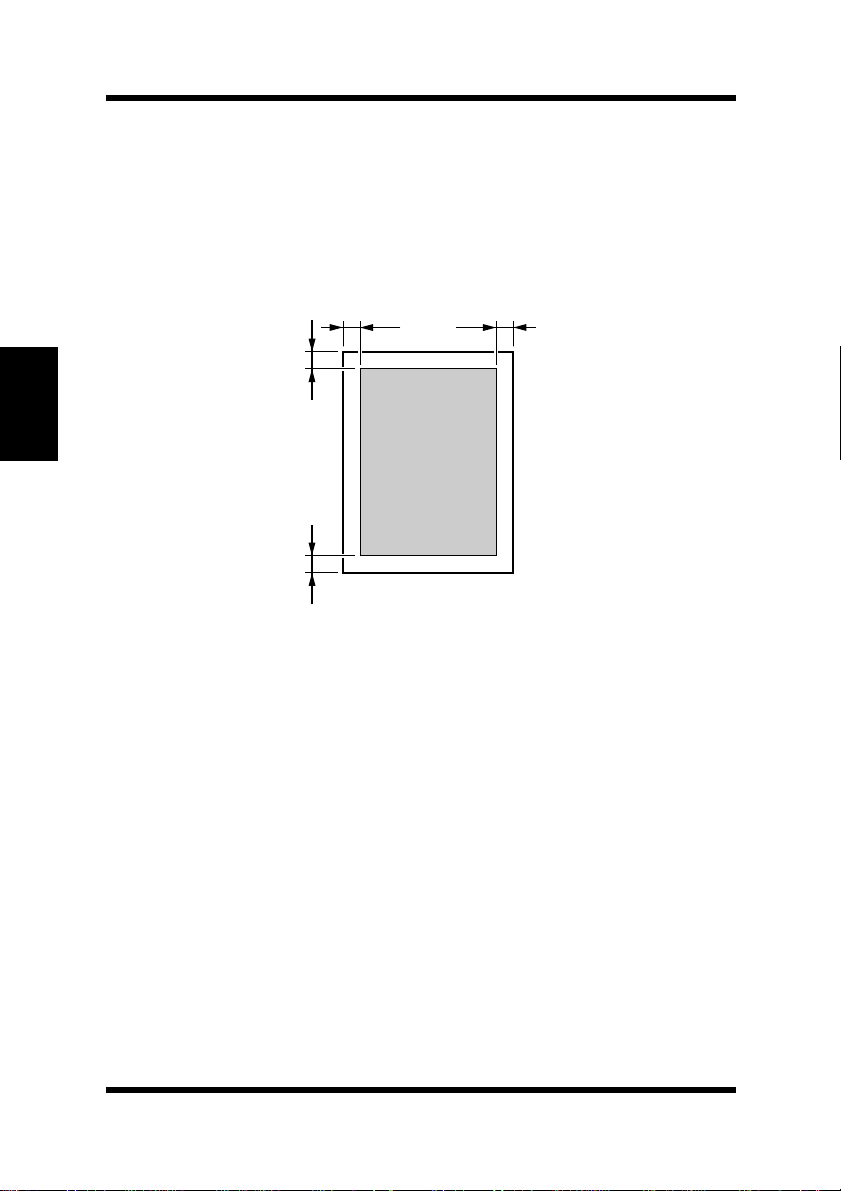
This printer is desi gned to pri nt on paper wi th a 4 mm (0.16 in.) margi n
on all sides.
4 mm
(0.16 in.)
4 mm
(0.16 in.)
Chapter 3Using the Printer
Printable
4 mm
(0.16 in.)
area
4 mm
(0.16 in.)
3-6
Page 63

Loading Paper
Loading Paper
The following sources can be used to feed paper into the printer:
•Tray1
• Manual feed tray
• Tray2 (option)
Tray1 is the standard source for s upplying p ape r to t he pr inter. Various
types and sizes of paper can be fed from this tray.
You can also add Tray2 as a secondary paper source. See “Second
Paper Cassette Unit” on page 2-18 for details on using this tray unit.
Whenever you are using special size paper, be sure to use the printer
driver installed on the computer to specify the printin g area. You may
experience some variation in print quality when using special size
paper.
Always remember that paper storage conditions greatly affect print
quality. Store paper in its original package. Keep paper out of areas
subject to extreme temperatures or humidity.
Chapter 3Using the Printer
3-7
Page 64

Loading Paper
Loading Paper onto Tray1
You can load up to 150 sheets of st andard pap er ont o T r ay 1. See “P rinting Paper” on page 3-3 for details on paper sizes and types.
1
Squeeze the right paper guide and open the paper guides.
Chapter 3Using the Printer
2
Place a stack of paper in the center of Tray1. Squeeze the right
paper guide and adjust the paper guides so that both the left and
the right sides of the paper stack are secure.
Maximum level
mark
Paper guide
3-8
Page 65
Loading Paper
Note
◆ A maximum level mark on the paper guide shows how high you
can stack paper on Tray1. Make sure that paper is stacked no
higher than this mark.
◆ Do not load additional paper until the paper currently loaded onto
T r ay1 is completely used.
◆ Never load paper while the printer is performing a reset operation.
See “Counter Reset Mode” on page 3-1 for details.
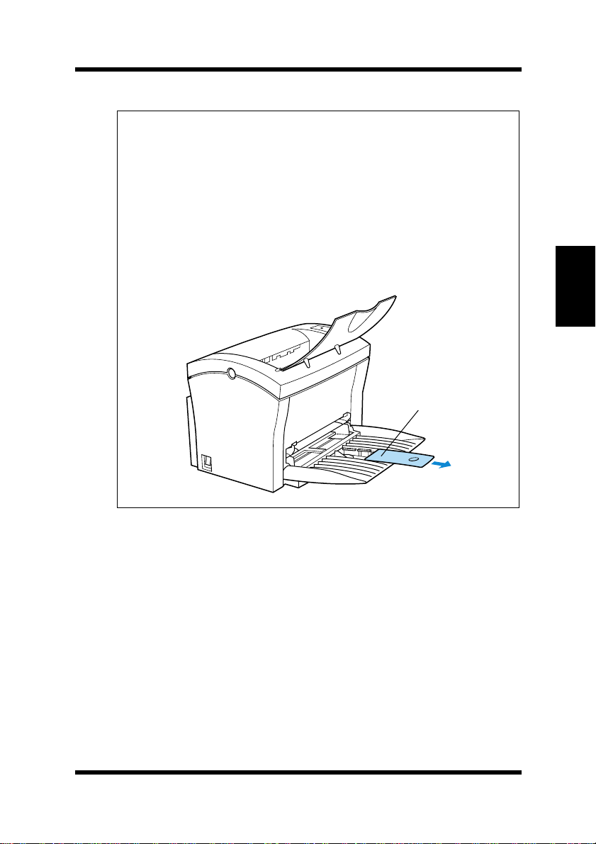
◆ Pull out the paper support in Tray1 when printing on Legal size
paper .
Paper support
Chapter 3Using the Printer
3-9
Page 66
Loading Paper
Manual Loading (Manual Feed Tray)
1
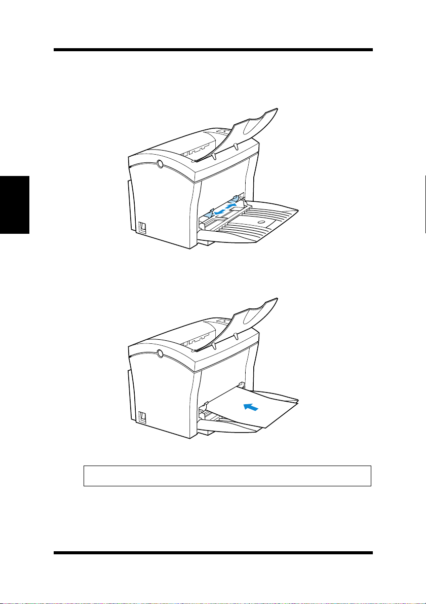
Open the paper guides.
Chapter 3Using the Printer
2
Insert the sheet of paper into the manual feed tray with the side
to be printed facing up.
3-10
Note
Insert only one sheet of paper at a time when feeding manually.
◆
Page 67
Loading Paper
3
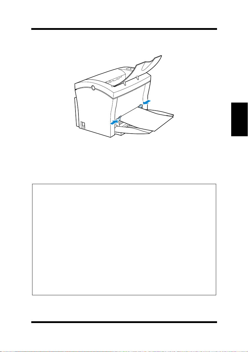
Adjust the paper guides so that both sides of the paper are
secure.
Printing on Envelopes
The manual feed tray supports Commercial 10, Monarch, DL, C5, and
B5 envelopes.
Note
Because there is great variation in the quality of paper used for enve-
◆
lopes, we suggest that you produce test prints of various types before
purchasing any envelope in large quantities for use with this printer.
Make sure that all edges are creased sharply and that all flaps are folded
◆
correctly.
Do not use env elopes that are self-adh esiv e. Use only envelopes that have
◆
standard sealing that sticks after it is moistened.
Use envelopes of which flaps run the entire length of the envelope. Enve-
◆
lopes that seal at one end will not feed properly.
Do not use envelopes that have a window. Such envelopes can seriously
◆
damage the printer.
Do not use envelopes that are wrinkled.
◆
Never use envelopes that have clasps or any other type of fastener that
◆
can damage the printer.
Do not store envelopes in an area that is subject to high humidity.
◆
Chapter 3Using the Printer
3-11
Page 68
Loading Paper
1
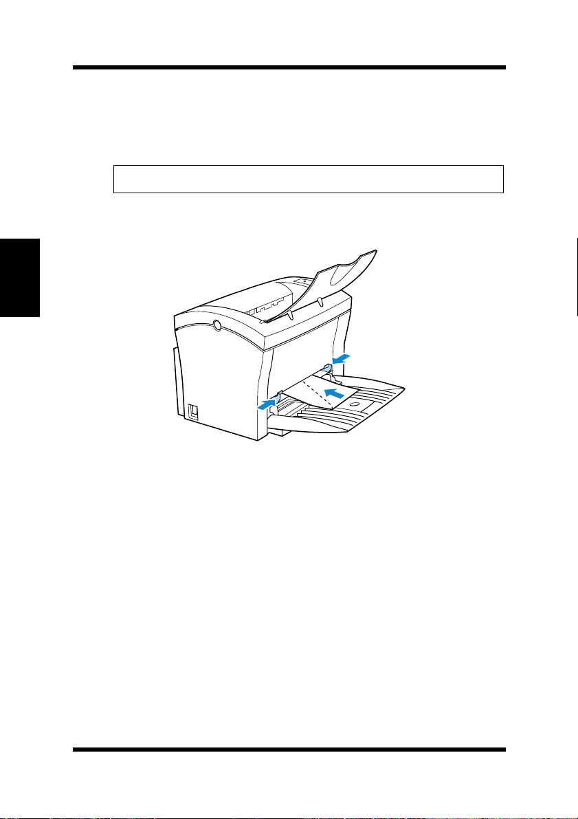
Place the envelope with the side to be printed facing up on the
tray. The flap of the envelope should be facing down and to the
left.
Note
Insert only one envelope at a time when feeding manually.
◆
2
Make sure that the envelope is placed in the center of the tray
and that it is secured by the paper guides.
Chapter 3Using the Printer
3-12
Page 69
Loading Paper
Loading Paper onto Tray2 (Option)
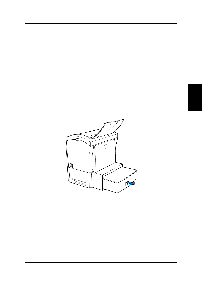
You can load up to 500 sheets of standard paper onto Tray2. See
“Printing Paper” on page 3-3 for details on paper sizes and types.
Note
Make sur e th at the
◆
ing has been installed into the
Paper Cassette Unit” on page 2-18 for instructions on inserting (and
removing) th e
To remove
◆
force. Then gently raise the forward-end up, and remove
unit.
1
Slide Tray2 out of the second paper cassette unit.
Tray2
for the proper size of paper to be used fo r print -
second paper cassette unit
Tray2
into (and from) the
Tray2
from the unit, pull it out as far as it will go without
second paper cassette unit
. See “Second
Tray2
.
from the
Chapter 3Using the Printer
3-13
Page 70
Loading Paper
2
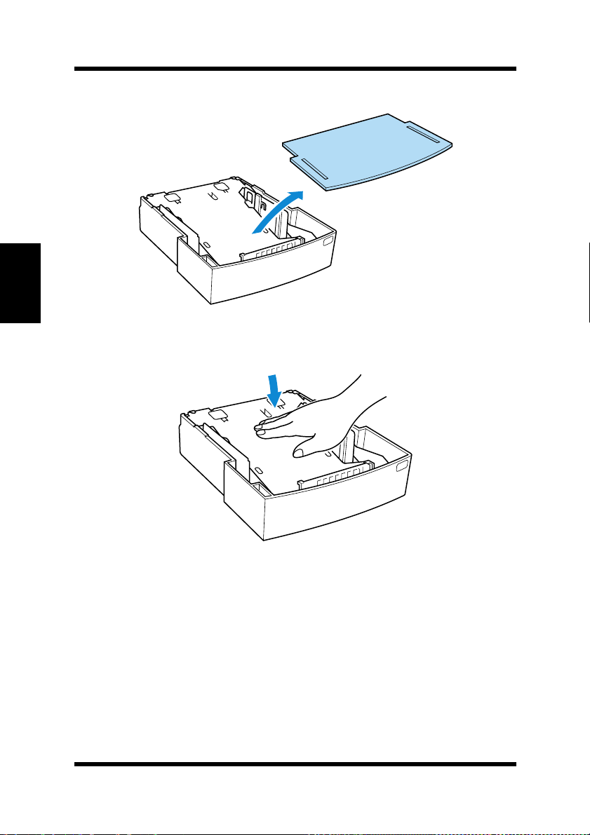
Remove the cassette cover from Tray2.
Chapter 3Using the Printer
3
Press down on the paper lifting plate located inside of Tray2
until it locks.
3-14
Page 71
Loading Paper
4
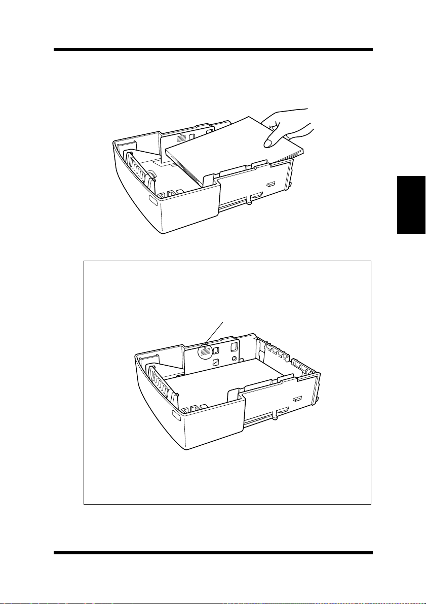
Place a stack of up to 500 sheets of paper into Tray2 so that the
side that was facing up when the paper was unwrapped is still
facing up.
Note
Chapter 3Using the Printer
maximum level mark
A
◆
high you can stack paper on
stacked no higher than this mark.
Tray2
◆
◆
does not support landscape oriented paper feeding.
Do not load additional paper until all the paper currently on
is completely used up.
inside the inlet of
Tray2
. Make sure that paper is
Maximum level mark
Tray2
shows how
Tray2
3-15
Page 72
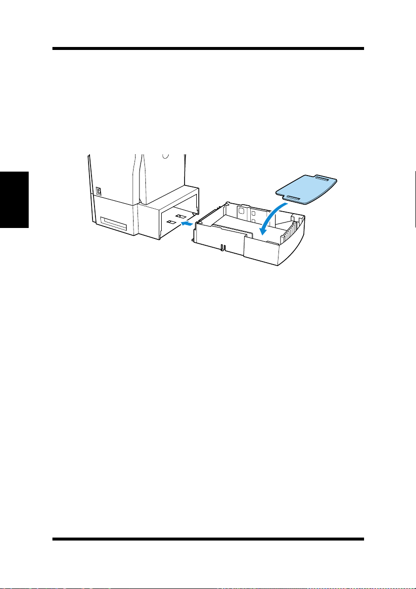
Loading Paper
5
Replace the cassette cover and insert Tray2 into the second
paper cassette unit.
Chapter 3Using the Printer
3-16
Page 73
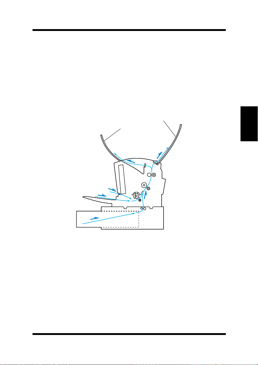
Selecting Output Direction (Printed Side Up or Down)
Selecting Output Direction (Printed Side
Up or Down)
The optional face-up tray, as explained earlier in this section is a useful tool for printing on thick paper or envelopes printed side up. The
factory default for the output tray however, is the face-down tray
(printed side down). In this mode, the outpu t tray receives the pr inted
documents in order.
Face-up tray (option)
Face-down tray
Chapter 3Using the Printer
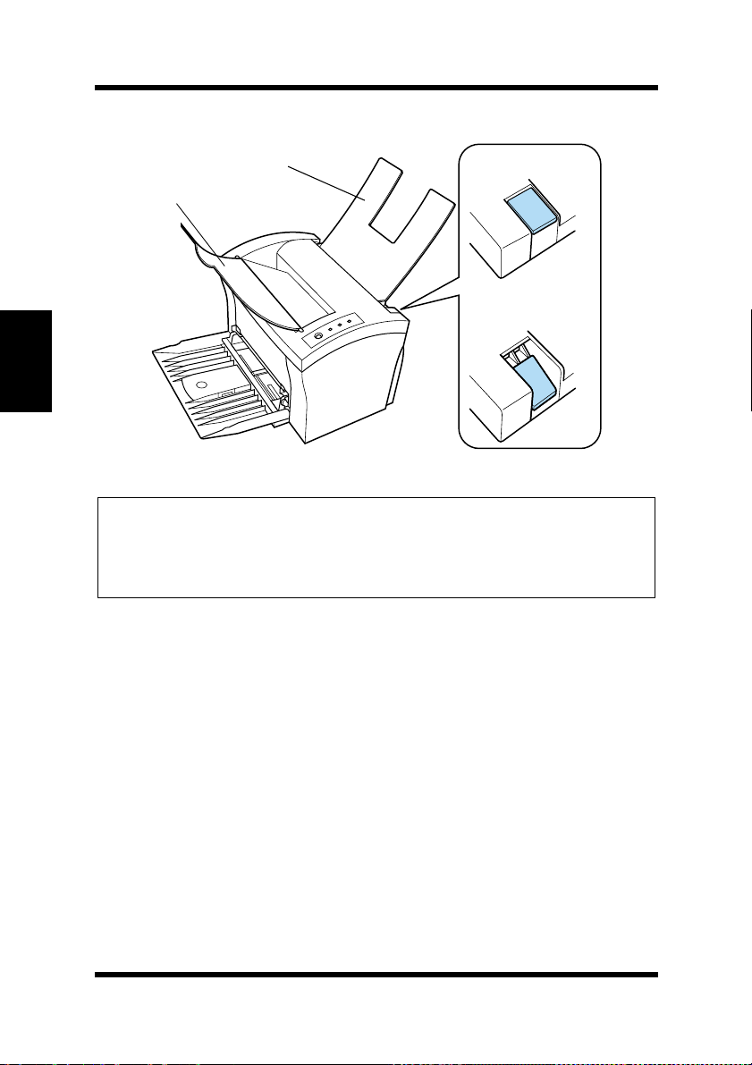
This setting is controlled by a switch which is located on the right side
of the printer toward the rear.
a. When the switch is flush with the top of the printer, prints are output
printed side down (factory default).
b. When the switch is pressed in, prints are output printed side up.
3-17
Page 74
Selecting Output Direction (Printed Side Up or Down)
Face-up tray
Face-down tray
Chapter 3Using the Printer
Face-down tra y
Face-up tray
Note
◆ Do not use the switch to change the setting while the printer is operating.
◆ Whenever the face-up tray is not installed on the printer, check to make
sure the set to switch for output to the face-down tray (see above illus-
tration).
3-18
Page 75

4Chapter
Printer Driver
Chapter 4Printer Driver
4
Page 76

Chapter 4Printer Driver
Page 77

Introduction
Introduction
The Minolta PagePro 1100 Printer Driver was specially developed to
provide true Windows-based and MS-DOS printing for users of the
Minolta/QMS PagePro 1100 printer. The PagePro 1100 Printer Driver
consists of two programs: Minolta PagePro Printer Driver and the
Printer Status Monitor, whic h also includes a Contro l Panel.
Printer Driver :
This program is built into the operating system. It controls printer
operations and enables proper printing.
Status Monitor:
This program displays information about the current status of the
computer’s local printer.
Control Panel:
This program displays the current settings of the computer’s local
printer. You can also use Control Panel to change settings and to
reset counters.
Chapter 4Printer Driver
4-1
Page 78

Chapter 4Printer Driver
System Requirements
System Requirements
The following describes the minimum system requirements that are
necessary to correctly run the Minolta PagePro 1100 Printer Driver.
Operating System: Mic rosoft Windows 95, Windo ws 98, W indo ws 3.1,
Windows NT 4.0 or MS-DOS
Personal Computer: IBM-compatible PC with at least a 386DX
16MHz CPU (Pentium processor recommended)
CD-ROM drive
I/O Interface: IEEE 1284 parallel
Memory: At least 8MB of PC R AM
Free Disk Space: Approximately 10MB for files
4-2
Page 79

Installing the PagePro 1100 Printer Driver Under Windows 95/
Windows 98/Windows NT 4.0
Installing the PagePr o 1100 Printer Driver Under Windows 95/Windows 98/ Windows NT 4.0
This section provides information on installing the PagePro 1100
Printer Driver under Windows 95, Windows 98 or Windows NT 4.0.
You can use the following methods to install the PagePro 1100 Printer
Driver.
Windows 95Windows 98Windows
NT 4.0
Using the auto-run
Installer on the CDROM
❍❍ ❍
Plug and Play Installation
Using the Add Printer
Wizard
❍
: Available
–: Not available
❍
❍❍
––
Chapter 4Printer Driver
–
4-3
Page 80
Chapter 4Printer Driver
Installing the PagePro 1100 Printer Driver Under Windows 95/
Windows 98/Windows NT 4.0
To Install the PagePro 1100 Printer Driver Using the Installer (Auto Run)
1
Turn on your computer and s tart up W indo ws 95, W indo ws 98 or
Windows NT 4.0.
Note
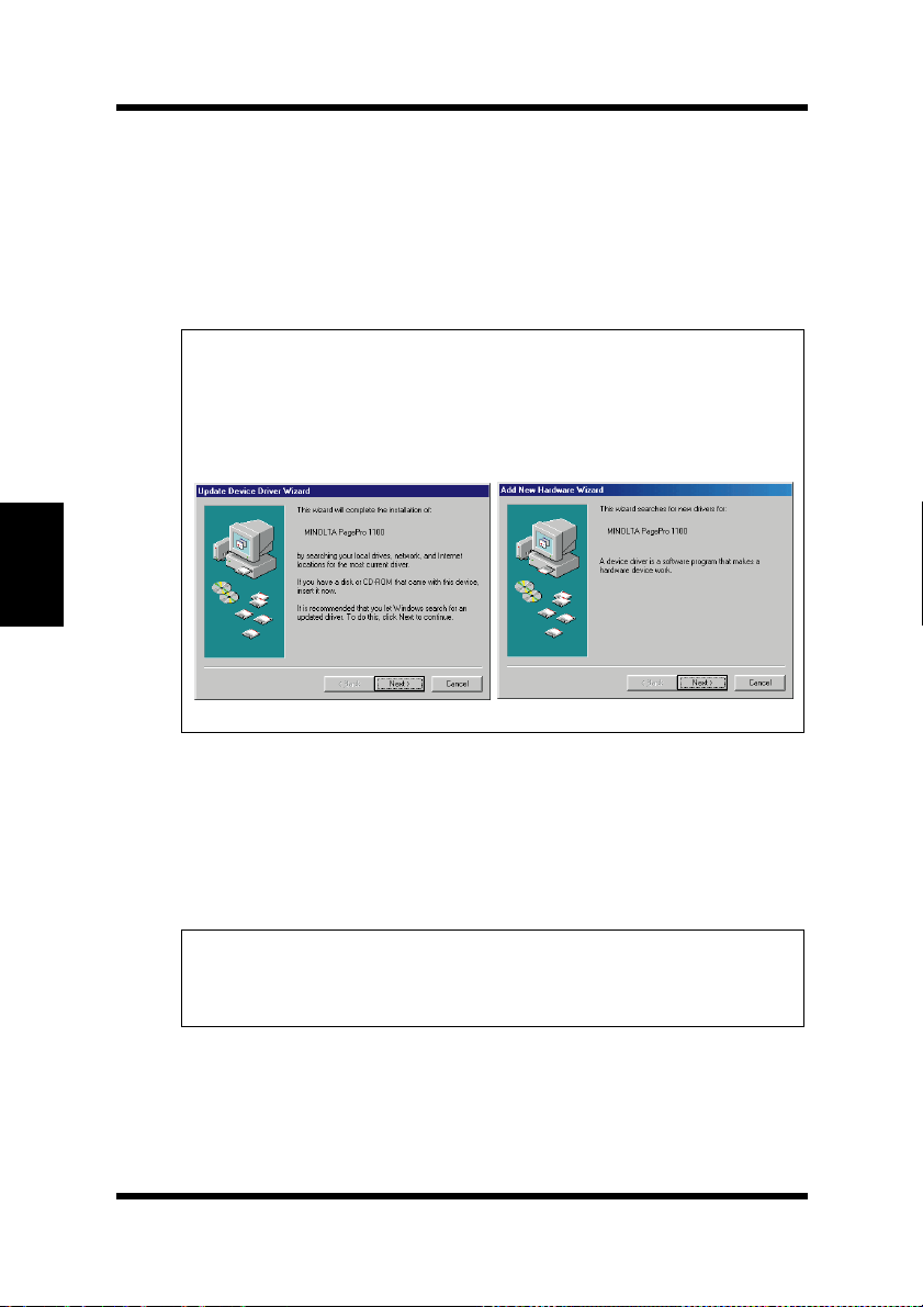
Under Windows 95 or Windows 98 when the
◆
Driver Wizard
the display, click
Windows 95 Windows 98
or
Add New Hardware Wizard
.
Cancel
Update Device
dialog appears on
2
Insert the CD-ROM labeled
Printer Drivers
3
The opening screen is automatically displayed. Click on the
Printer Driver
into your computer’s CD-ROM drive.
menu to start the Installer.
Minolta/QMS PagePro 1100
Note
The configuration of some computers may prevent the opening
◆
screen from appearing automatically. If the screen does not
appear, double-click
from the CD-ROM.
Setup
4-4
Page 81
Installing the PagePro 1100 Printer Driver Under Windows 95/
Windows 98/Windows NT 4.0
4
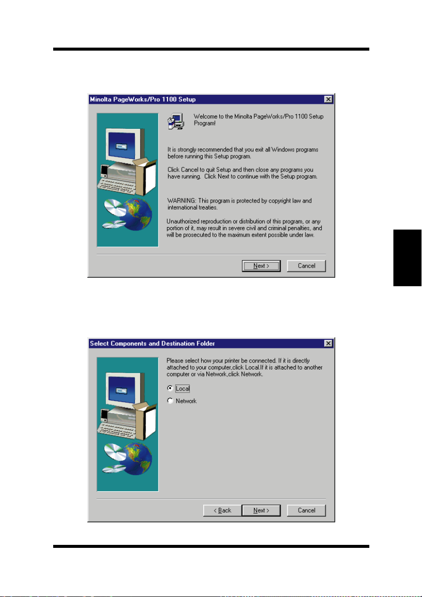
Follow the instructions that appear on your computer screen to
complete the installation.
5
When the follow in g dial og appears, select Local if the printer is
connected directly to your computer or
connected through a network. Then click
Network if the printer is
Next.
Chapter 4Printer Driver
4-5
Page 82
Chapter 4Printer Driver
Installing the PagePro 1100 Printer Driver Under Windows 95/
Windows 98/Windows NT 4.0
Caution
◆ If you intend to access the printer from a server running Win-
dows 95, first install the printer’ s driver fr om the s erv er using
the Installer. The Installer can be accessed through either the
autorun program or the
◆ If you find that your printer is unable to print documents in a
network environment, set the data-spool format of the client
to RAW.
6
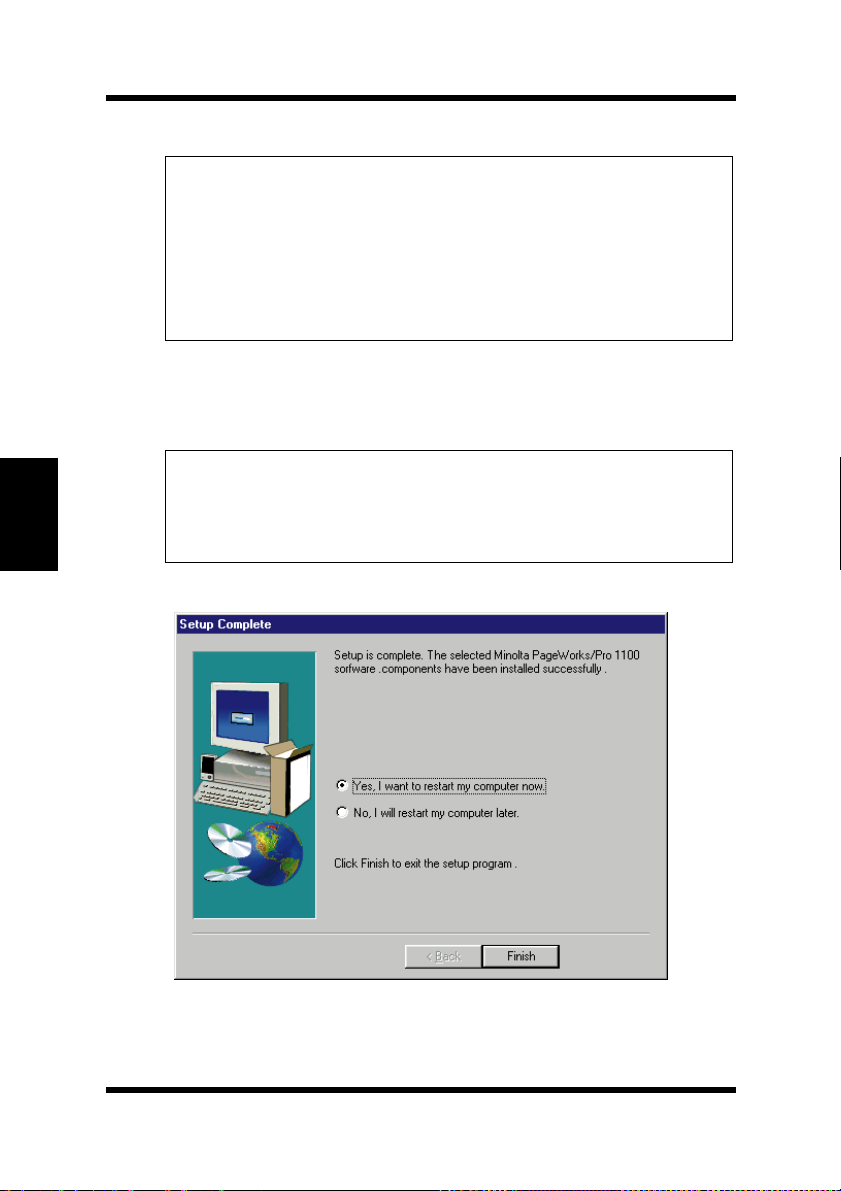
After the installation is completed, the following dialog appears.
Finish
Click
to close the setup program window.
Setup file of the CD-ROM.
Note
During installation, it may take a moment before the Setup Com-
◆
plete dialog box appears if there was a check beside the
box in the Select Components and Destination Folder dia-
Tools
log box.
Printer
4-6
Page 83
Installing the PagePro 1100 Printer Driver Under Windows 95/
Windows 98/Windows NT 4.0
Note
It is recommended that you restart your computer after installa-
◆
tion.
7
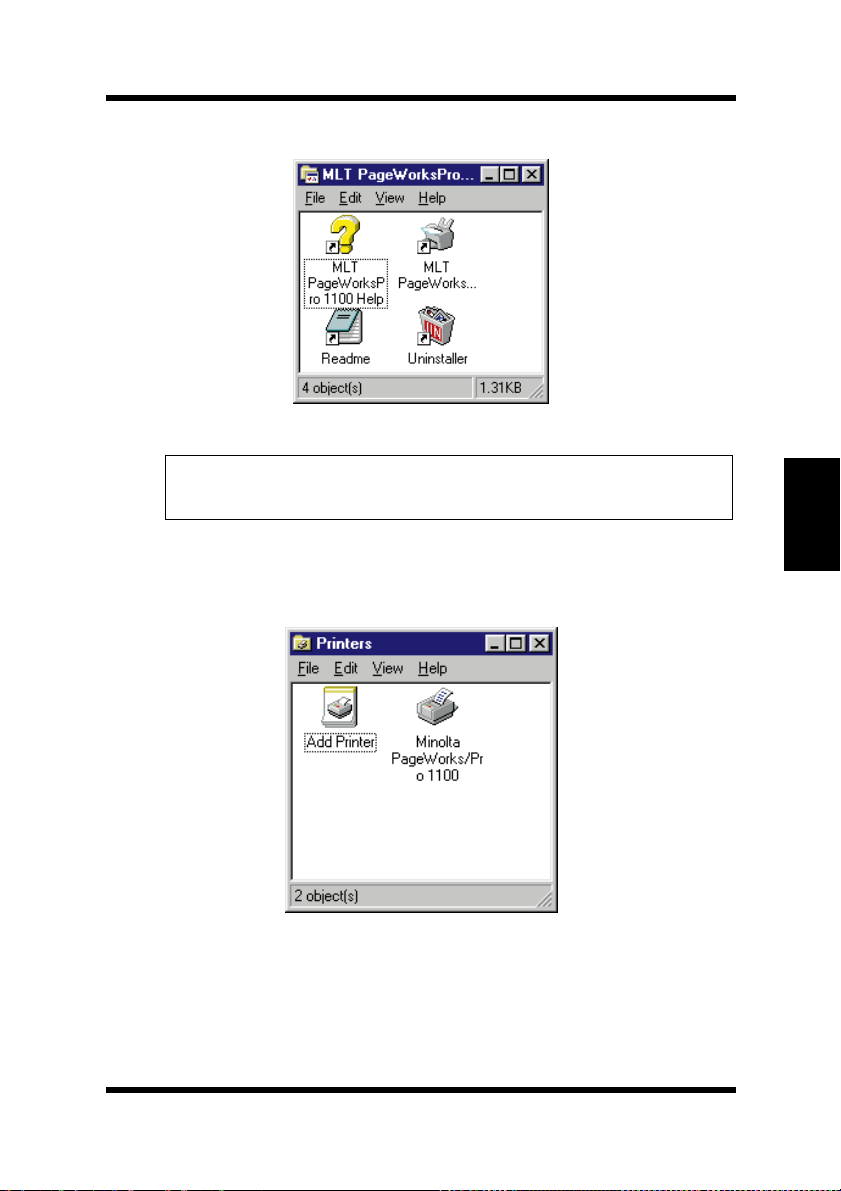
Check that the
played in the Printers dialog. To display the Printers dialog, click
Start
, point to
8
Eject the CD-ROM labeled
Printer Drivers
This completes the installation of Minolta PagePro 1100 printer
driver.
Minolta PageWorks/ P ro 1100
Settings
from your computer’s CD-ROM drive.
, and then click
Minolta/QMS PagePro 1100
printer icon i s di s-
Printers
.
Chapter 4Printer Driver
4-7
Page 84
Chapter 4Printer Driver
Installing the PagePro 1100 Printer Driver Under Windows 95/
Windows 98/Windows NT 4.0
To Install the PagePro 1100 Printer Driver Using Plug-and-Play
1
After connecting the printer to your computer, turn on the
printer.
• See “Connecting to a Computer” on page 2-17 for details on
connecting the printer to your computer.
2
Turn on your computer and start up Windows 95.
3
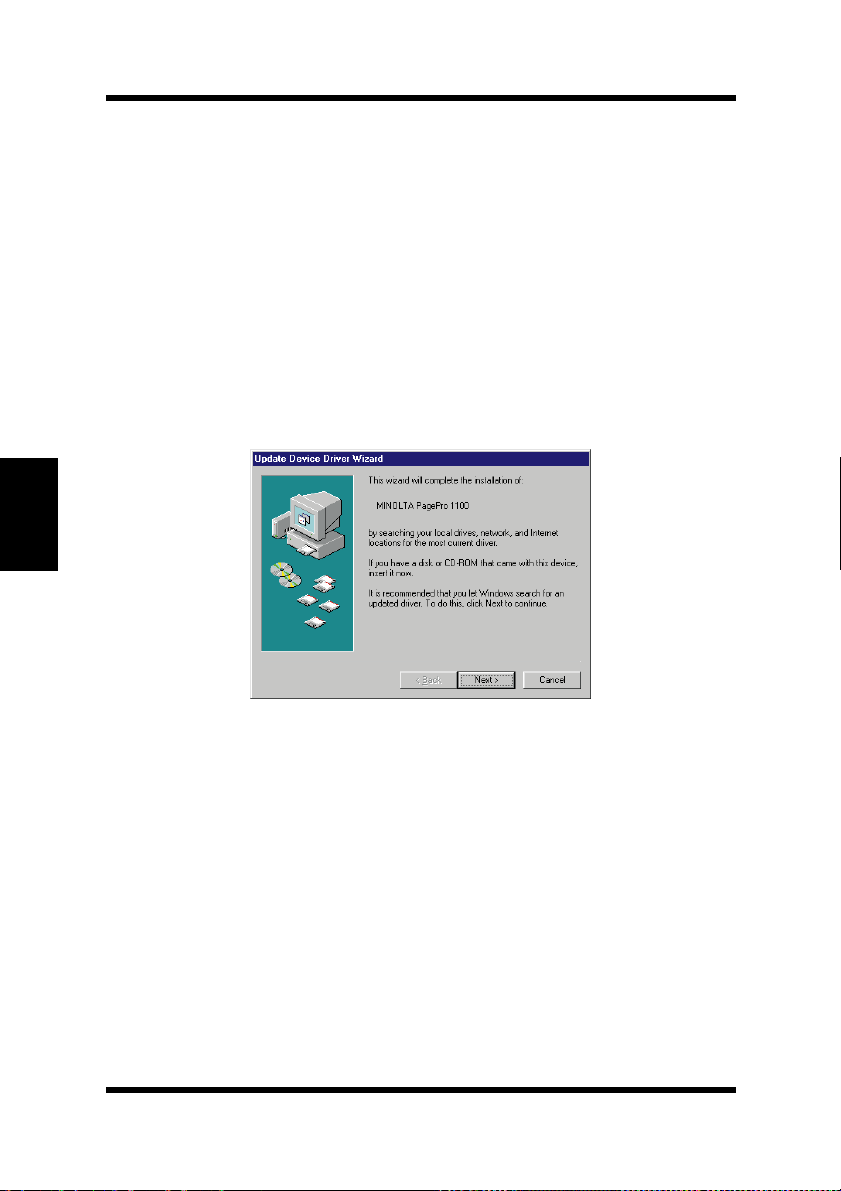
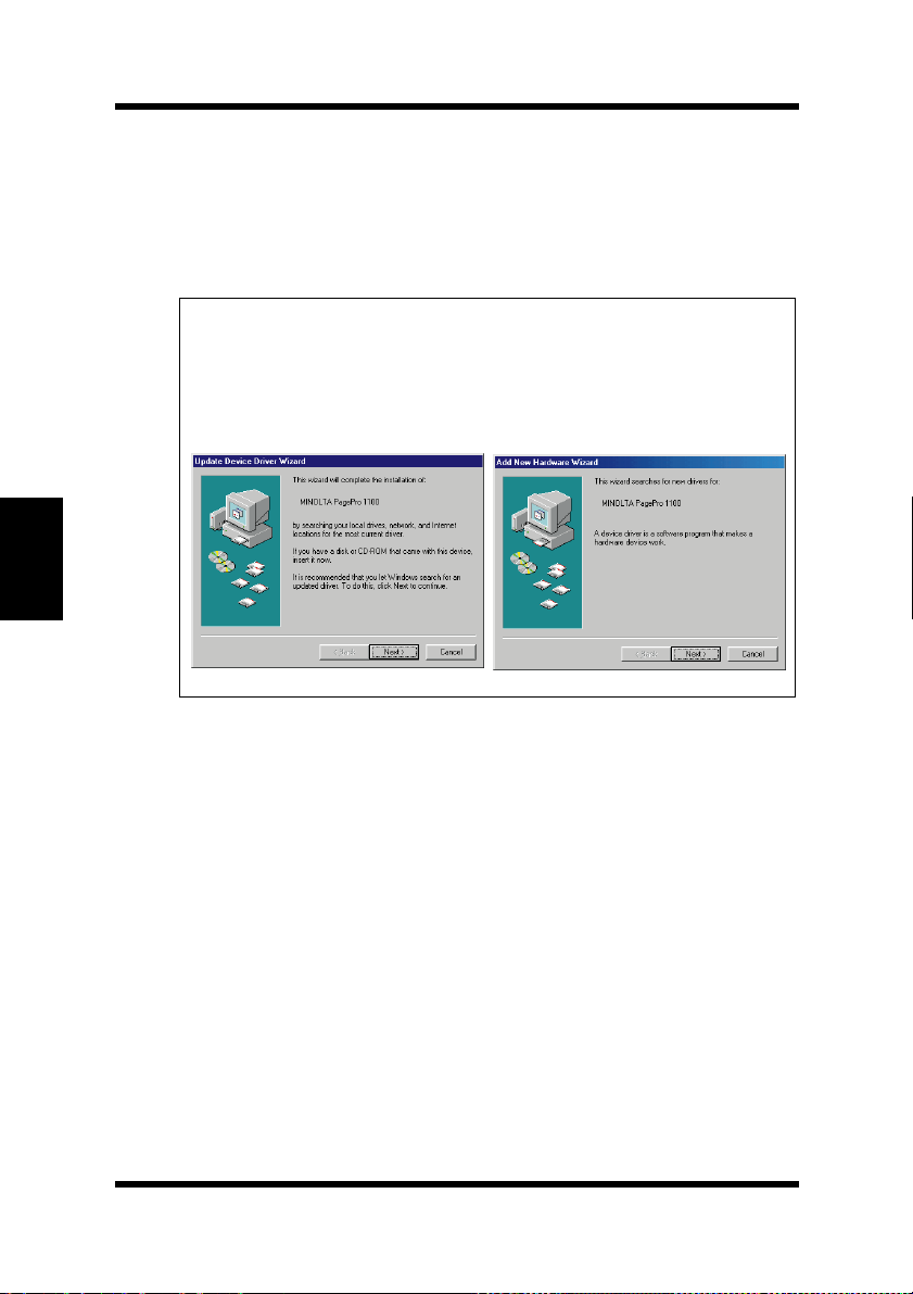
Continue with step 4 when the
dialog shown below appears.
Update Device Driver Wizard
4
Insert the CD-ROM labeled
Printer Drivers
click
• In this example, we assume that
ROM drive.
5
Click the
and click
.
Next
Other Locations
.
OK
4-8
Minolta/QMS PagePro 1100
into your computer’s CD-ROM drive, and then
is the name of the CD-
D:
button, type
D:\driver\9598addp
Page 85
Installing the PagePro 1100 Printer Driver Under Windows 95/
Windows 98/Windows NT 4.0
6
Follow the instructions that appear on your computer screen to
complete the installation.
Note
An opportunity to designate a name for the printer will be pro-
◆
vided during the installation procedure.
It is recommended that you restart your computer after installa-
◆
tion.
7
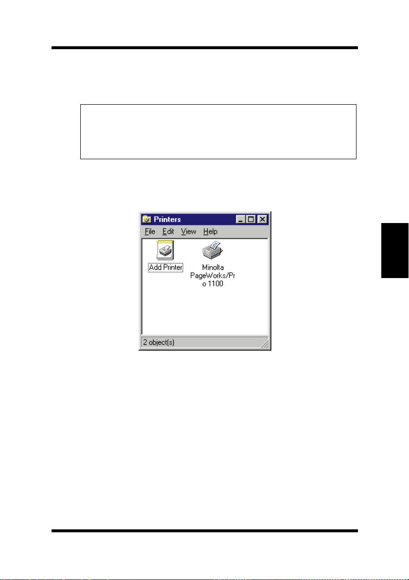
Check that the
played in the Printers dialog. To display the Printers dialog, click
Start
, point to
8
Eject the CD-ROM labeled
Printer Drivers
This completes the installation of Minolta PagePro 1100 printer
driver.
Minolta PageWorks/ P ro 1100
Settings
from your computer’s CD-ROM drive.
, and then click
Minolta/QMS PagePro 1100
printer icon i s di s-
Printers
.
Chapter 4Printer Driver
4-9
Page 86
Chapter 4Printer Driver
Installing the PagePro 1100 Printer Driver Under Windows 95/
Windows 98/Windows NT 4.0
To Install the PagePro 1100 Printer Driver Using the Add Printer Wizard
1
Turn o n your c omputer and start up Windows 95 or Windo ws 9 8.
Note
Under Windows 95 or Windows 98 when the
◆
Driver Wizard
the display, click
Windows 95 Windows 98
or
Add New Hardware Wizard
.
Cancel
Update Device
dialog appears on
2
Insert the CD-ROM labeled
Printer Drivers
• When the initial screen appears, click
3
Click
Start
, point to
4-10
Minolta/QMS PagePro 1100
into your computer’s CD-ROM drive.
to close it.
Quit
Settings
, and then click
Printers
.
Page 87
Installing the PagePro 1100 Printer Driver Under Windows 95/
Windows 98/Windows NT 4.0
4
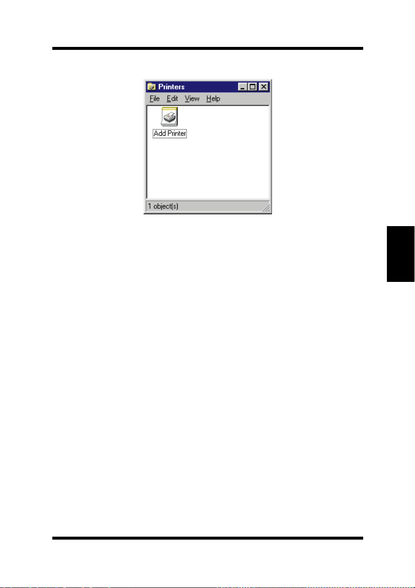
Double-click the Add Printer icon.
5
Click Next.
6
Select Local Printer if the printer is conne cted directly to your
computer’s parallel port or select
is connected through a network.
7
If you selected Network Printer in step 5, specify the network
path and the network printer you want to use. If you selected
Local Printer, skip this step.
Network Printer if the printer
Chapter 4Printer Driver
8
Click Have Disk.
9
Browse to the Minolta/QMS PagePro 1100 Printer Drivers CDROM and navigate to:
10
Click OK and then click Next.
11
Follow the instructions that appear on your computer screen to
complete the installation.
driver\9598addp. Next, click OK.
4-11
Page 88

Installing the PagePro 1100 Printer Driver Under Windows 3.1
Installing the PagePr o 1100 Printer Driver
Under Windows 3.1
This section provides information on installing the printer dr iver on a
computer running Windows 3.1.
Note
The printer driver must be installed using the Installer of the printer
◆
driver’s CD-ROM. Do not use the Add printer from the Printers dialog.
To Install the PagePro 1100 Printer Driver
1
Turn on your computer and start up Windows 3.1.
Chapter 4Printer Driver
2
Insert the CD-ROM labeled
Printer Drivers
3
Use File Manager to display the contents of the CD-ROM.
4
On the CD-ROM window (drive D: in this example), open the
folder named
5
Double-click
into your computer’s CD-ROM drive.
Driver
and then open the folder named
setup.exe
Minolta/QMS PagePro 1100
Disk 1
to start the Installer.
.
4-12
Page 89
Installing the PagePro 1100 Printer Driver Under Windows 3.1
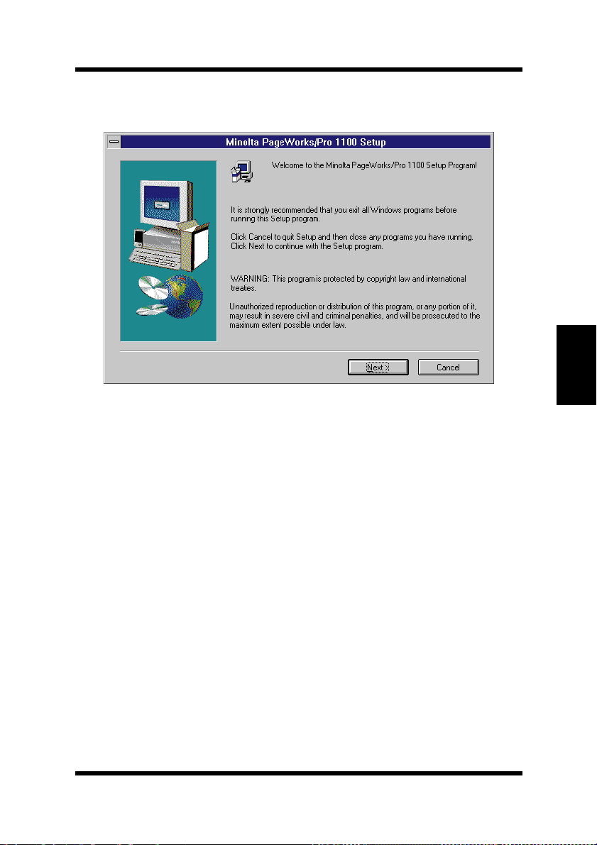
6
Follow the instructions that appear on your computer screen to
complete the installation.
Chapter 4Printer Driver
4-13
Page 90
Chapter 4Printer Driver
Installing the PagePro 1100 Printer Driver Under Windows 3.1
7
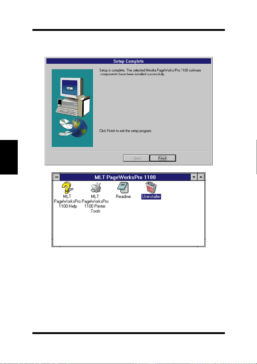
After the installation is completed, the following dialog appears.
Click
Finish to close the setup program window.
4-14
Page 91
Installing the PagePro 1100 Printer Driver Under Windows 3.1
8
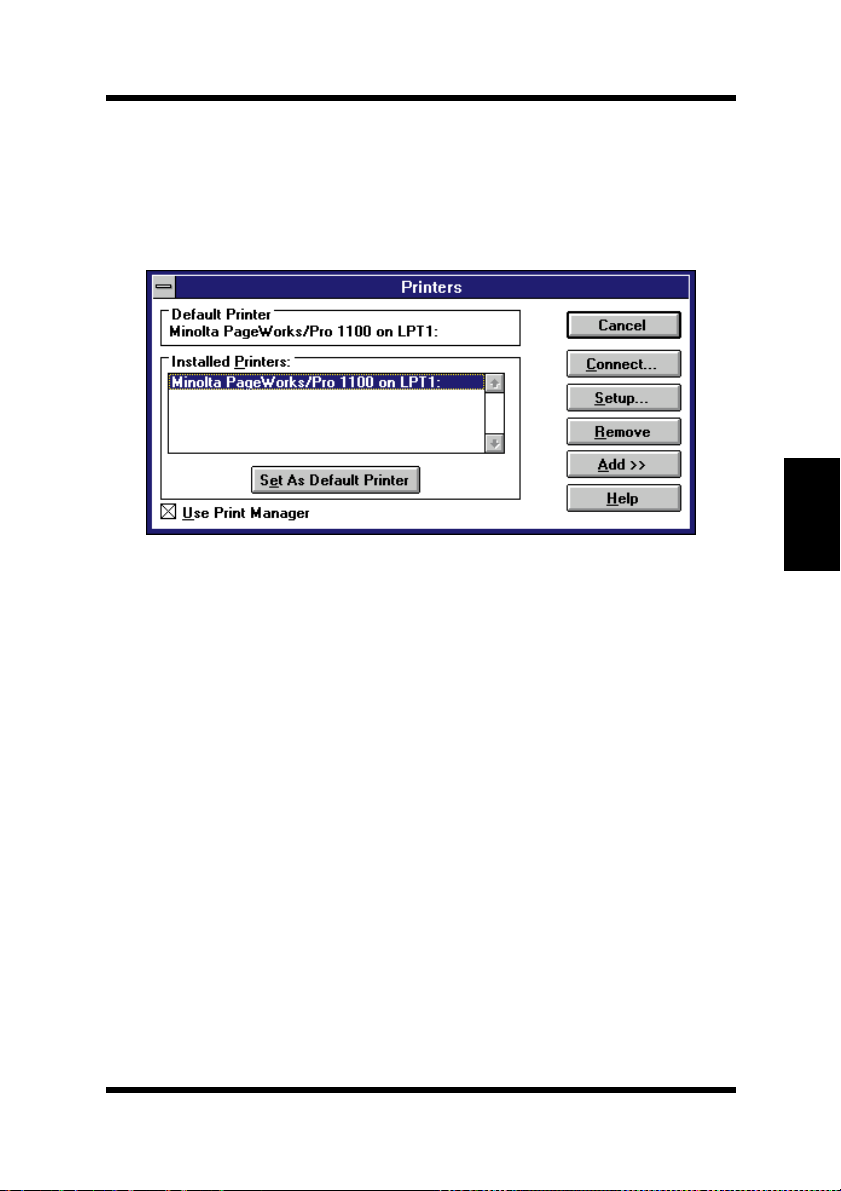
Check that Minolta PageWorks/Pro 1100 is displayed in the
Installed Printers: list in the Printers dialog.
To display the Printers dialog, double-click
which is located in the Mai n group wit hin the Pr ogram Manager,
and then double-click
9
Eject the CD-ROM labeled Minolta/QMS PagePro 1100
Printer Drivers
This completes the installation of Minolta PagePro 1100 printer
driver.
Printers in the Control Panel dialog.
from your computer’s CD-ROM drive.
Control Panel icon,
Chapter 4Printer Driver
4-15
Page 92
Displaying the PagePro 1100 Printer Driver Setup Dialog
Displaying the PagePro 1100 Printer
Driver Setup Dialog
To Display the Printer Driver Setup Dialog Under Windows 95/Windows 98
Chapter 4Printer Driver
1
2
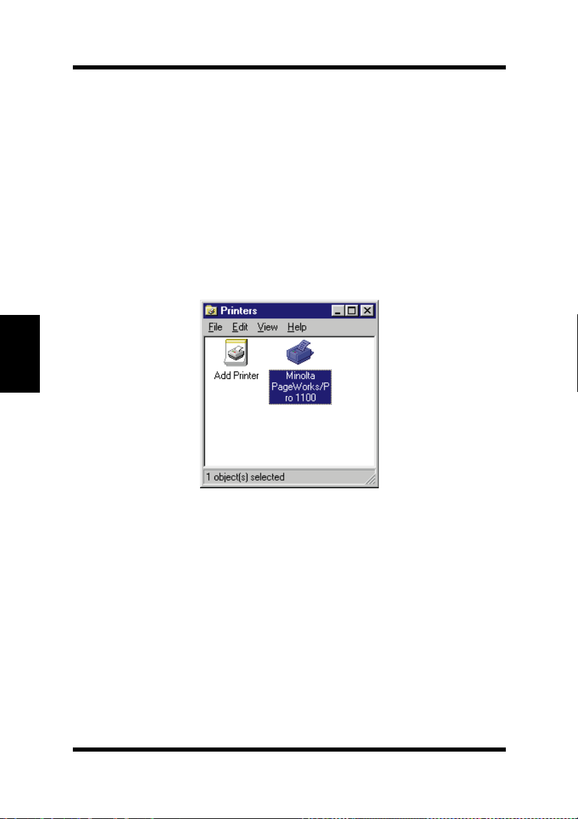
Start
Click
the Printers dialog.
In the Printers dialog, click the
printer icon.
, point to
Settings
and then click
Minolta PageWorks/Pro 1100
Printers
to display
4-16
Page 93
Displaying the PagePro 1100 Printer Driver Setup Dialog
3
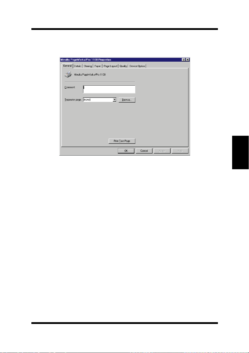
Select Properties from the File menu.
The following window appears.
Chapter 4Printer Driver
4-17
Page 94
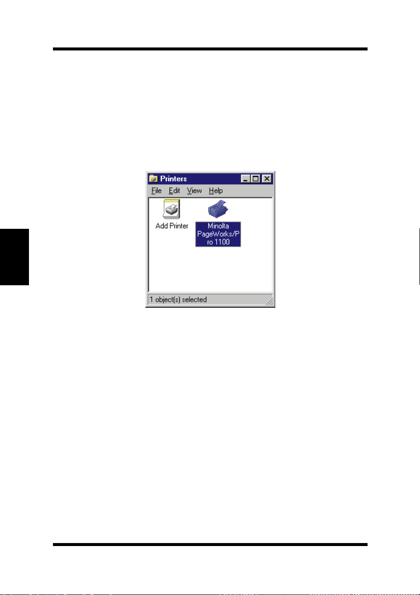
Chapter 4Printer Driver
Displaying the PagePro 1100 Printer Driver Setup Dialog
To Display the Printer Driver Setup Dialog Under Windows NT 4.0
1
Click
the Printers dialog.
2
In the Printers dialog, click the
printer icon.
Start
, point to
Settings
and then click
Minolta PageWorks/Pro 1100
Printers
to display
4-18
Page 95
Displaying the PagePro 1100 Printer Driver Setup Dialog
3
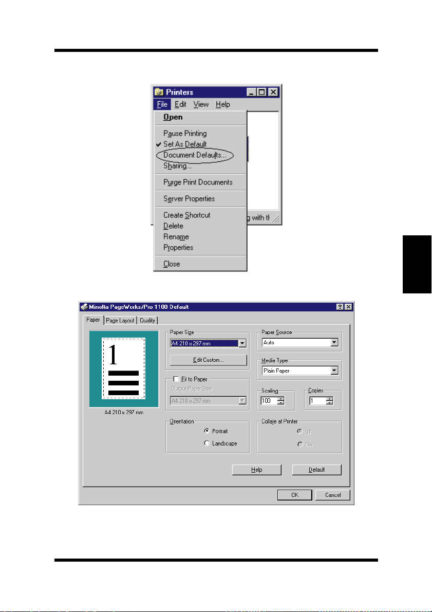
Select Document Defaults... from the File menu.
The following window appears.
Chapter 4Printer Driver
4-19
Page 96
Chapter 4Printer Driver
Displaying the PagePro 1100 Printer Driver Setup Dialog
4
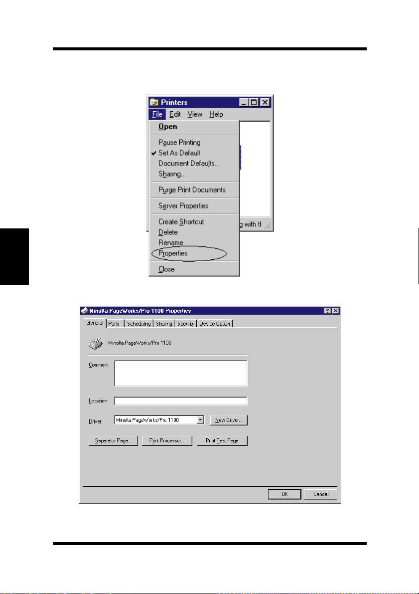
To change the de vice opt ion settings , select Prop erties from the
File menu.
The following window appears.
4-20
Page 97
Displaying the PagePro 1100 Printer Driver Setup Dialog
To Display the PagePro 1100 Printer Driver Setup Dialog Under Window 3.1
1
Double-click the
Main group within the Program Manager.
2
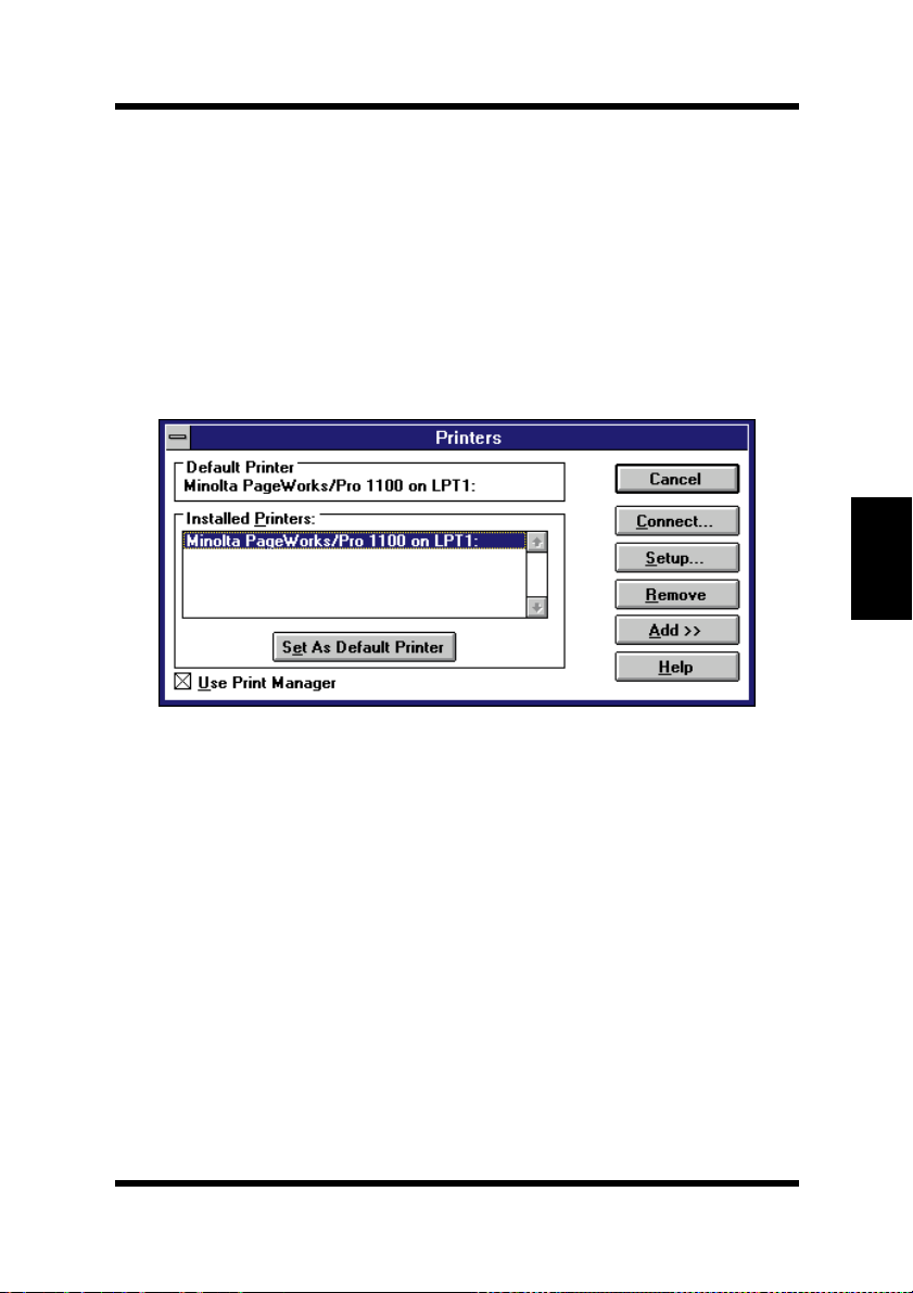
In the Control Panel dialog, double-click
3
In the Installed Printers: list, click
to select it.
1100
Control Panel
icon, which is located in the
Printers
Minolta PageWorks/Pro
.
Chapter 4Printer Driver
4-21
Page 98
Chapter 4Printer Driver
Displaying the PagePro 1100 Printer Driver Setup Dialog
4
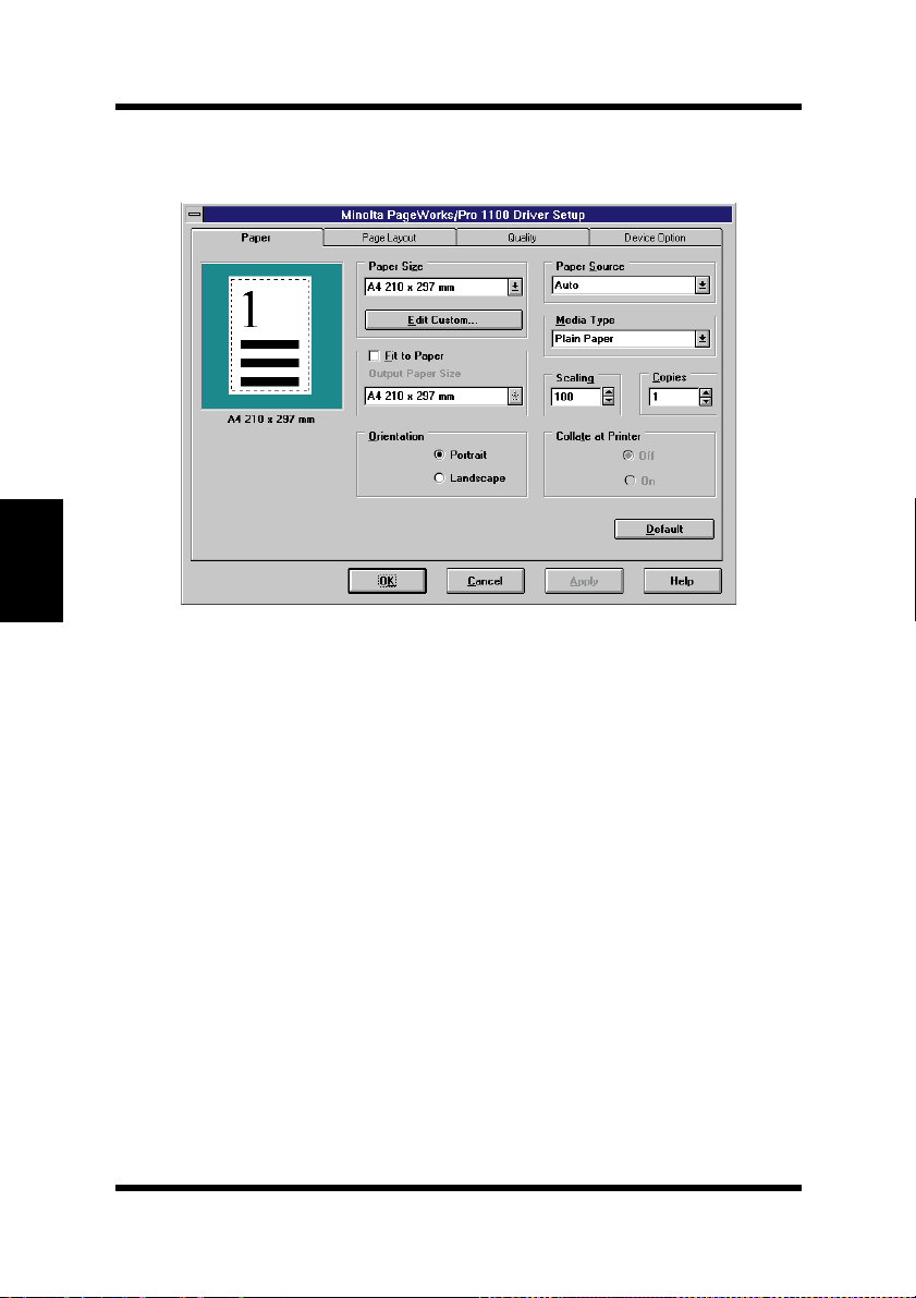
Click Setup, which displays the Setup dialog for PagePro 1100
printer.
4-22
Page 99

Using the PagePro 1100 Printer Driver Setup Dialog
Using the PagePro 1100 Printer Driver
Setup Dialog
The printer driver provides you with control over a wide variety of
printer parameters f rom your computer. The following sections pro vide
an overview of the seven tabs of the printer driver’s Properties dialog
box. The settings you make with the Properties dialog box become the
default settin gs for the Mi nolta Pa gePro 1100 Print er Driv er. To dis play
the dialog box, click
Next, right-click the
Properties
select
Start
, point to
Minolta PageWorks/Pro 1100
from the context menu that appears.
Common Buttons
The buttons described below appear at the bottom of each tab.
Settings
, and then click
icon and then
Printers
.
OK
Click to exit the Properties dialog box, saving any changes made.
Cancel
Click to exit the Properties dialog box without saving any changes
made.
Apply
Click to save all changes without exiting the Properties dialog box.
Help
Click to view online help.
Chapter 4Printer Driver
4-23
Page 100
Using the PagePro 1100 Printer Driver Setup Dialog
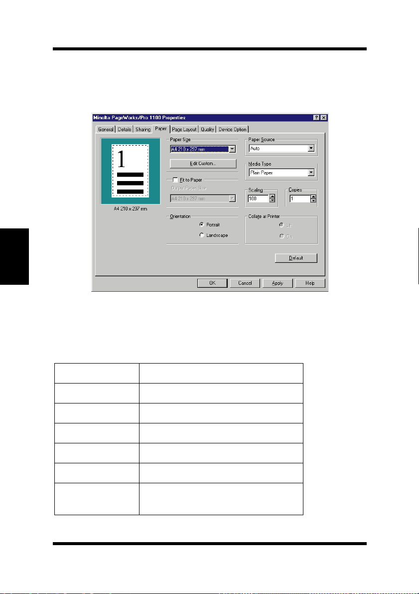
Paper
Chapter 4Printer Driver
The
tab contains functions that affect the format and output of
Paper
your printed documents.
Paper Size
Your printer supports the following paper and media sizes:
Paper
Letter 8-1/2 × 11 in.
Legal 8-1/2 × 14 in.
Executive 7-1/4 × 10-1/2 in.
A4 210 × 297 mm
A5 148 × 210 mm
JIS B5 182 × 257 mm
Custom Paper 76 to 216 mm × 127 to 356 mm, 3
to 8-1/2 in. × 5 to 14 in.
4-24
 Loading...