

Page 1

PROPRIETARY NOTICE AND LIABILITY DISCLAIMER
The information disclosed in this document, including all designs and related materials, is
the valuable property of NEC Computer Systems Division, Packard Bell NEC, Inc.
(hereinafter “NECCSD”) and/or its licensors. NECCSD and/or its licensors, as appropriate,
reserve all patent, copyright and other proprietary rights to this document, including all
design, manufacturing,reproduction, use, and sales rights thereto, except to the extent said
rights are expressly granted to others.
The NECCSD product(s) discussed in this document are warranted in accordance with the
terms of the Warranty Statement accompanying each product. However, actual
performance of each such product is dependent upon factors such as system configuration,
customer data, and operator control. Since implementation by customers of each product
may vary, the suitability of specific product configurations and applications must be
determined by the customer and is not warranted by NECCSD.
To allow for design and specification improvements, the information in this document is
subject to change at any time, without notice. Reproduction of this document or portions
thereof without prior written approval of NECCSD is prohibited.
FaxFlash is a trademark of NEC Computer Systems Division (NECCSD), Packard Bell NEC, Inc.
NEC is a registered trademark of NEC Corporation and PowerMate is a registered trademark of NEC Technologies, Inc.; these registered
trademarks are used under license by NEC Computer Systems Divison (NECCSD), Packard Bell NEC, Inc.
All other product, brand, or trade names used in this publication are the trademarks or registered trademarks of their respective trademark
owners.
First Printing — July 1997
Copyright 1997
NEC Computer Systems Division
Packard Bell NEC, Inc.
1414 Massachusetts Avenue
Boxborough, MA 01719-2298
All Rights Reserved
Page 2

Preface
This addendum to the PowerMate® Ve Series Service and Reference Manual (document
number 819-181516-000) provides updated information on the computer’s hardware for
users who need an overview of system design.
This information applies to computers with the following model numbers:
ET-1830-24813E
ET-1830-24813CE
ET-1860-24813E
ET-1860-24813CE.
This addendum also includes updated procedures for setting up and installing the system
and illustrated parts lists. The manual is written for NECCSD-trained customer engineers,
system analysts, service center personnel, and dealers.
v
The manual is organized as follows:
Section 1 — Technical Information, provides information not available when the
PowerMate Ve ETC Series User’s Guide (819-181780-000) was printed. System
specifications are listed including dimensions, weight, environment, safety compliance,
power consumption, and memory.
Section 2 — Setup and Installation, includes procedures for installing application
software and drivers and performing system backups. This section also provides information
not available when the PowerMate Ve ETC Series User’s Guide was printed.
Section 3 — Illustrated Parts Breakdown, provides an exploded view diagram of the
system. Also included are updated parts lists for field-replaceable parts.
Page 3

Contents
Preface.........................................................................................................................v
Section 1 Technical Information
System Overview.........................................................................................................1-1
SIMM Upgrade ...........................................................................................................1-2
Performing Memory Upgrades..............................................................................1-2
Locating SIMM Sockets.......................................................................................1-2
Checking System Memory.....................................................................................1-2
Installing SIMMS..................................................................................................1-3
Interrupt Controller......................................................................................................1-4
Integrated Graphics......................................................................................................1-5
Network Interface........................................................................................................1-5
Hard Disk Specifications..............................................................................................1-6
iii
System Specifications...................................................................................................1-7
Section 2 Setup and Installation
Section 3 Illustrated Parts Breakdown
List of Figures
1-1 Network Interface Board ...............................................................................1-5
2-1 Rear Panel I/O Ports ......................................................................................2-1
2-2 Network Interface Boad Connectors..............................................................2-2
3-1 PowerMate Ve ETC Series Illustrated Parts Breakdown ................................3-4
Page 4

iv Contents
List of Tables
1-1 PowerMate Ve ETC Series System Configurations ........................................1-1
1-2 Recommended Memory Upgrade Path ........................................................... 1-3
1-3 Interrupt Level Assignments...........................................................................1-4
1-3 Hard Disk Drive Specifications.......................................................................1-6
1-4 Specifications.................................................................................................1-7
3-1 PowerMate Ve ETC Series Field-Replaceable Parts List ................................3-2
3-2 PowerMate Ve ETC Series Documentation and Packaging ............................3-5
Page 5

Section 1
Technical Information
This section describes hardware features and components that are specific to the
PowerMate® Ve ETC Series of NEC PowerMate Ve Series computers. For information
that is general to all PowerMate Ve Series computers, see the PowerMate Ve Series Service
and Reference Manual (part number 819-181528-000).
SYSTEM OVERVIEW
PowerMate Ve ETC Series computers are configured with a different system board and
come with a network interface board installed as standard equipment in one of the system
unit expansion slots.
PowerMate Ve ETC Series computers include the configurations identified in Table 1-1.
Table 1-1 PowerMate Ve ETC Series System Configurations
Model Number
ET-1830-24813E
(PowerMate V133e)
ET-1830-24813CE
(PowerMate V133e)
ET-1860-24813E
(PowerMate V133e)
ET-1860-24813CE
(PowerMate V166e)
Processor Multimedia
133-MHz
®
Intel
Pentium
133-MHz
Intel
Pentium
166-MHz
Intel
Pentium
133-MHz
Intel
Pentium
No 16 MB 1 MB fast video
®
Yes
No 16 MB 1 MB video
Yes 16 MB 1 MB video
System
Memory Video Memory Hard Disk
1.2-GB IDE
16 MB
dynamic
random-access
memory(video
DRAM)
1 MB video
DRAM
DRAM
DRAM
(WDAC21200)
1.2-GB IDE
(WDAC21200)
1.2-GB IDE
(WDAC21200)
1.2-GB IDE
(WDAC21200)
Multimedia systems come with audio components integrated on the system board.
Multimedia systems also include an eight-speed CD-ROM reader installed in the system
unit, 8-watt speakers, and a microphone.
Page 6

1-2 Technical Information
SIMM UPGRADE
PowerMate Ve ETC Series system configurations come with 16 MB of main system
memory. Four sockets on the system board support up to 128 MB of high-speed memory
using the following industry-standard, tin-plated, single in-line memory modules (SIMMs):
NOTE:
nonparity, extended data output (EDO) SIMMs
into the SIMM sockets.
1-MB by 32- or 36-bit (4-MB stick)
2-MB by 32- or 36-bit (8-MB stick)
4-MB by 32- or 36-bit (16-MB stick)
8-MB by 32- or 36-bit (32-MB stick).
You may install 60-ns, parity or
CAUTION:
To avoid corrosion between
different metals, only use tin-plated SIMM sticks.
The system board can use 64-MB SIMMs (16-MB by 32- or 36-bit), but these SIMMs are
not supported by NECCSD for the PowerMate Ve ETC Series.
Performing Memory Upgrades
Upgrade system memory as follows:
locate memory sockets on system board
check installed system memory
install SIMMs.
Locating SIMM Sockets.
Remove the system unit cover and locate the six SIMM sockets on the system board (see
Section 3 of the PowerMate Ve Series Service and Reference Manual).
If any cables block access to the SIMM sockets, label and disconnect them. If any boards
block access to the sockets, remove them.
Checking System Memory
Use Table 1-2 to check the memory installed in the system and determine the SIMM
configuration needed to increase memory.
Page 7

Technical Information 1-3
NOTE: SIMM memory must be installed in
pairs of the same memory type.
Table 1-2 Recommended Memory Upgrade Path
Total Bank 0 Bank 1
Memory SIMM 1 SIMM 2 SIMM 3 SIMM 4
16 MB 4 MB 4 MB 4 MB 4 MB
16 MB* 8 MB 8 MB Empty Empty
24 MB 4 MB 4 MB 8 MB 8 MB
24 MB 8 MB 8 MB 4 MB 4 MB
32 MB 8 MB 8 MB 8 MB 8 MB
32 MB 16 MB 16 MB Empty Empty
40 MB 4 MB 4 MB 16 MB 16 MB
40 MB 16 MB 16 MB 4 MB 4 MB
48 MB 8 MB 8 MB 16 MB 16 MB
48 MB 16 MB 16 MB 8 MB 8 MB
64 MB 16 MB 16 MB 16 MB 16 MB
64 MB 32 MB 32 MB Empty Empty
72 MB 32 MB 32 MB 4 MB 4 MB
72 MB 4 MB 4 MB 32 MB 32 MB
80 MB 8 MB 8 MB 32 MB 32 MB
80 MB 32 MB 32 MB 8 MB 8 MB
96 MB 16 MB 16 MB 32 MB 32 MB
96 MB 32 MB 32 MB 16 MB 16 MB
128 MB 32 MB 32 MB 32 MB 32 MB
* = Standard configuration.
Installing SIMMS
After determining the system memory upgrade path, install SIMMs using the installation
procedure provided in Section 3 of the PowerMate Ve Series Service and Reference
Manual.
Page 8

1-4 Technical Information
INTERRUPT CONTROLLER
The interrupt controller operates as an interrupt manager for the entire AT system
environment. The controller accepts requests from peripherals, issues interrupt requests to
the processor, resolves interrupt priorities, and provides vectors for the processor to
determine which interrupt routine to execute. The interrupt controller has priority
assignment modes that can be reconfigured at any time during system operations.
The interrupt levels are described in Table 1-3. Interrupt-level assignments 0 through 15 are
in order of decreasing priority. See Section 2 of the PowerMate Ve Series Service and
Reference Manual for information on changing the interrupts using Setup.
Table 1-3 Interrupt Level Assignments
Interrupt Assignment
IRQ 0 Counter/Timer
IRQ 1 Keyboard
IRQ 2(9) Cascade (INT output from slave)
IRQ 3 COM2 and COM4
IRQ 4 COM1 and COM3
IRQ 5 Parallel Port 2/Audio (if present)
IRQ 6 Diskette Drive Controller
IRQ 7 Parallel Port 1
IRQ 8 Real-time clock
IRQ 10 Available/Audio (if present)
IRQ 11 Network Interface Board
IRQ 12 PS/2 mouse
IRQ 13 Coprocessor
IRQ 14* Primary IDE
IRQ 15* Secondary IDE
Page 9
Technical Information 1-5
INTEGRATED GRAPHICS
PowerMate Ve ETC Series computers have an SiS 6205 PCI graphics and video controller
integrated on the system board. State of the art techniques are used for optimizing
performance in computer graphic intensive applications and graphical user interfaces (GUI).
PowerMate Ve ETC Series systems have 1 MB of video DRAM on the system board. For
information about graphics features and video support, see Section 1 of the PowerMate Ve
Series Service and Reference Manual.
NETWORK INTERFACE
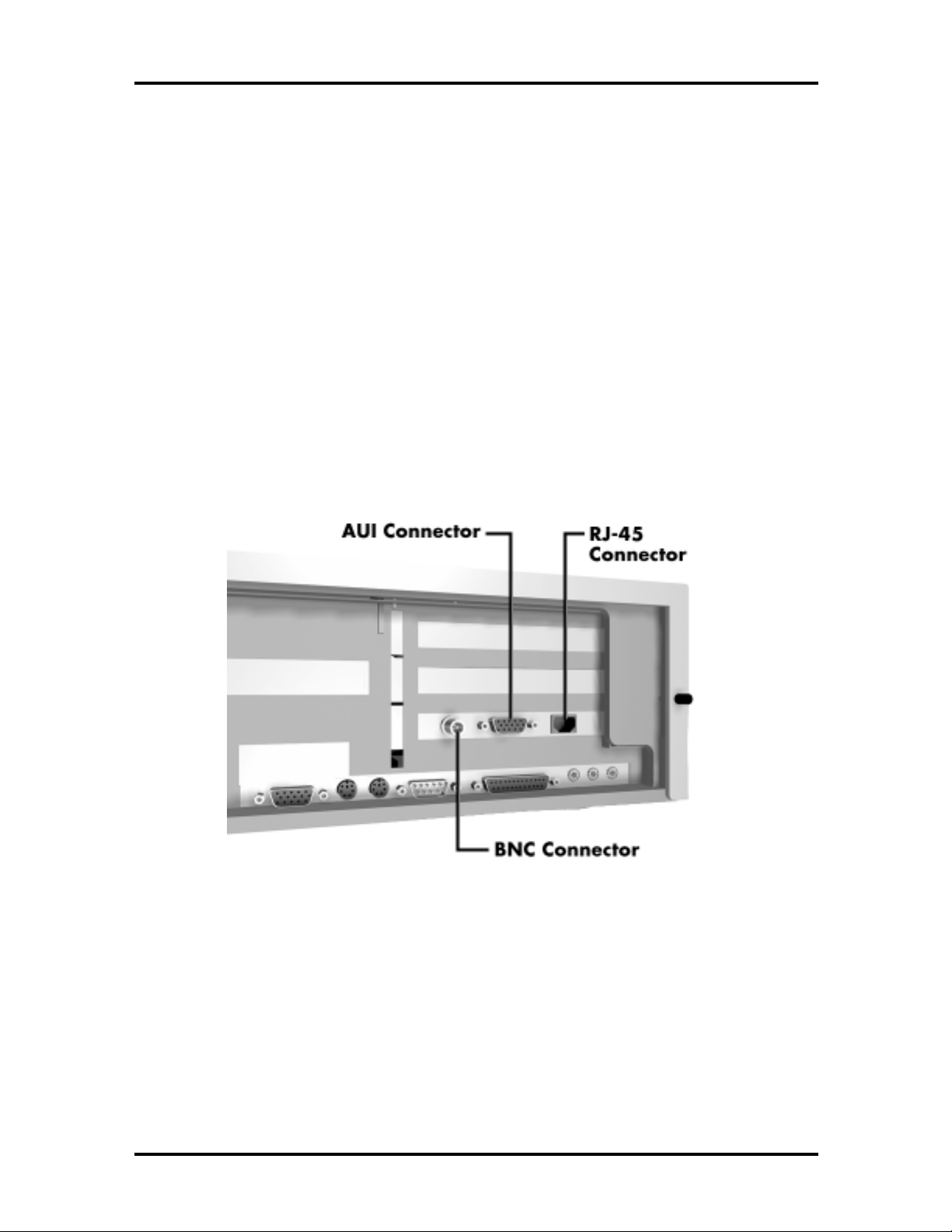
The computer comes equipped with a network interface board installed in one of the
expansion slots in the system unit. The three connectors on the board allow connection to
an Ethernet network and communication with other computers. Access to the connectors is
provided at the rear of the system unit. Figure 1-1 shows the location of the network
interface board and the three connectors. For more information, see Section 2 of this
addendum.
Figure 1-1 Network Interface Board
Page 10

1-6 Technical Information
g
g
g
HARD DISK SPECIFICATIONS
The PowerMate Ve ETC Series computer contains a 1.2-GB Western Digital IDE hard
disk. The following table provides hard disk specifications.
Table 1-4 Hard Disk Drive Specifications
Features Specification
Physical Configuration
Formatted Capacity 1.278 GB
Actuator Type Rotary voice-coil
Number of Disks 3
Data Heads 6
Servo Type Embedded
Tracks per Inch (tpi) 3,849 tpi
Bytes per Sector 512
Maximum Data
Rate from Media
Dimensions
ht
Hei
th
Len
Width
Weight 1.3 lb (589.4)
Performance
Track-to-track seek
Avera
Maximum seek
Average Latency 8.3 ms
Rotation Speed 3600 rpm
Data Transfer Rate
(buffer to disk)
Data Transfer Rate
(buffer to host)
e seek
45.4 MB/second
1.00 in. (25.4 mm)
5.75 in. (146.0 mm)
4.00 in. (101.6 mm)
3.0 ms
14 ms
26 ms
45.4 MB/s maximum
16.6 MB/s, Mode 4
Start/Stop Cycles 40,000 minimum
Buffer Size 64 KB
Interface IDE
Page 11

SYSTEM SPECIFICATIONS
g
g
y
g
y
y
System specifications are included in Table 1-5.
Table 1-5 Specifications
Item Specification
Dimensions and Weight
System Unit Width: 17 inches (43.18 cm)
Depth: 16 inches (40.64 cm)
ht: 4 inches (10.6 cm)
Hei
Weight: 22 lb (11.1 kg), dependent upon options
Keyboard Width: 19.0 inches (48.3 cm)
Depth: 8.4 inches (21.3 cm)
ht: 1.6 inches (4.1 cm)
Hei
Weight: 3.5 to 4.0 lb. (1.6 to 1.8 kg)
Device Bays Two 5 1/4-inch front accessible bays
One 3 1/2-inch front accessible ba
One 3 1/2-inch internal bay
Technical Information 1-7
Expansion Slots Four slots:
two 16-bit ISA slots
one ISA/PCI shared slot
one PCI slot
One ISA slot contains the network interface board.
Network Interface 3COM 3C509B ISA 10 Megabit board with adapter (RJ-45, AUI,
10BASE-T)
Access to the connectors is provided at the rear of the system
unit. All confi
the hard drive.
Peripheral Interface PS/2-style keyboard connector, rear panel
PS/2-st
Two RS-232C serial ports, rear panel
Parallel printer port, rear panel
VGA port, rear panel
Front Panel Power button
Power indicator lamp
Hard disk drive bus
Suspend button
Reset button
Processor Intel Pentium 133- or 166-MHz (dependent on system)
urations come with Ethernet drivers preloaded on
le mouse connector, rear panel
indicator lamp
Cache Memory 16 KB of primary cache (8 KB data, 8 KB instruction) integrated
in the processor, 256 KB secondary cache
Flash ROM 128 KB (28F001) Flash ROM
Chip Set SiS5511+/5512/5513 PCI/ISA
Page 12

1-8 Technical Information
y
y
y
g
y
g
y
y
Table 1-5 Specifications
Item Specification
System Memor
16-MB EDO standard, expandable to 128 MB using SIMM
sockets
Optional SIMMs 4-, 8-, 16-, and 32-MB; 32-bit, non-parity, 70-ns SIMMs
Integrated Graphics SiS 6205 PCI Graphics & Video Accelerator
1-MB video DRAM standard
Maximum resolution 1280 x 1024 pixels
Battery Coin-type battery
Power Supply 145 Watt, 115 V/230V switch selectable
CD-ROM Reader
(Multimedia only)
See Appendix D of the service manual for more specifications
Disc format: ISO 9660
Data transfer rate: 600 KB/sec, PIO Mode 3 support
Access time (t
pical): 500 msec
Built-in buffer: 128 KB
Host interface: IDE (ATAPI)
Integrated Sound Standard in multimedia systems
ESS1688 Sound Blaster
Yamaha OPL3 FM S
®
SRS
Labs 3D sound solution
16-bit 128x oversamplin
®
compatible
nthesis
sigma-delta stereo CODEC with
85 dB S/N ratio
Stereo jacks for microphone: line in and line out
Wave Blaster upgradeable for wavetable synthesis
Goldtron Microphone
Standard in multimedia s
Omnidirectional
30dB
8-Watt Speakers
(Goldtron Speakers)
Standard in multimedia systems
netic shielded 8-watt stereo speakers
Ma
Power on/off switch, power lamp, volume, bass and treble
controls
Mini-stereo headphone jack
Built in stereo amplifier
9-volt AC power adapter
Operating Environment
Temperature 50
Relative Humidity 20% to 80%
Administrative Compliance UL 1950 - safet
CSA C22.2 No. 950-m89
TUV EN60950: 1988
FCC part 15, Subpart J, Class B - emissions
FCC part 68
C.R.C., c.1374
IEC 950 - safet
VDE 0871/6.78, Class B - emissions
stems
o
F to 95oF (10oC to 35oC)
Page 13
Section 2
Setup and Installation
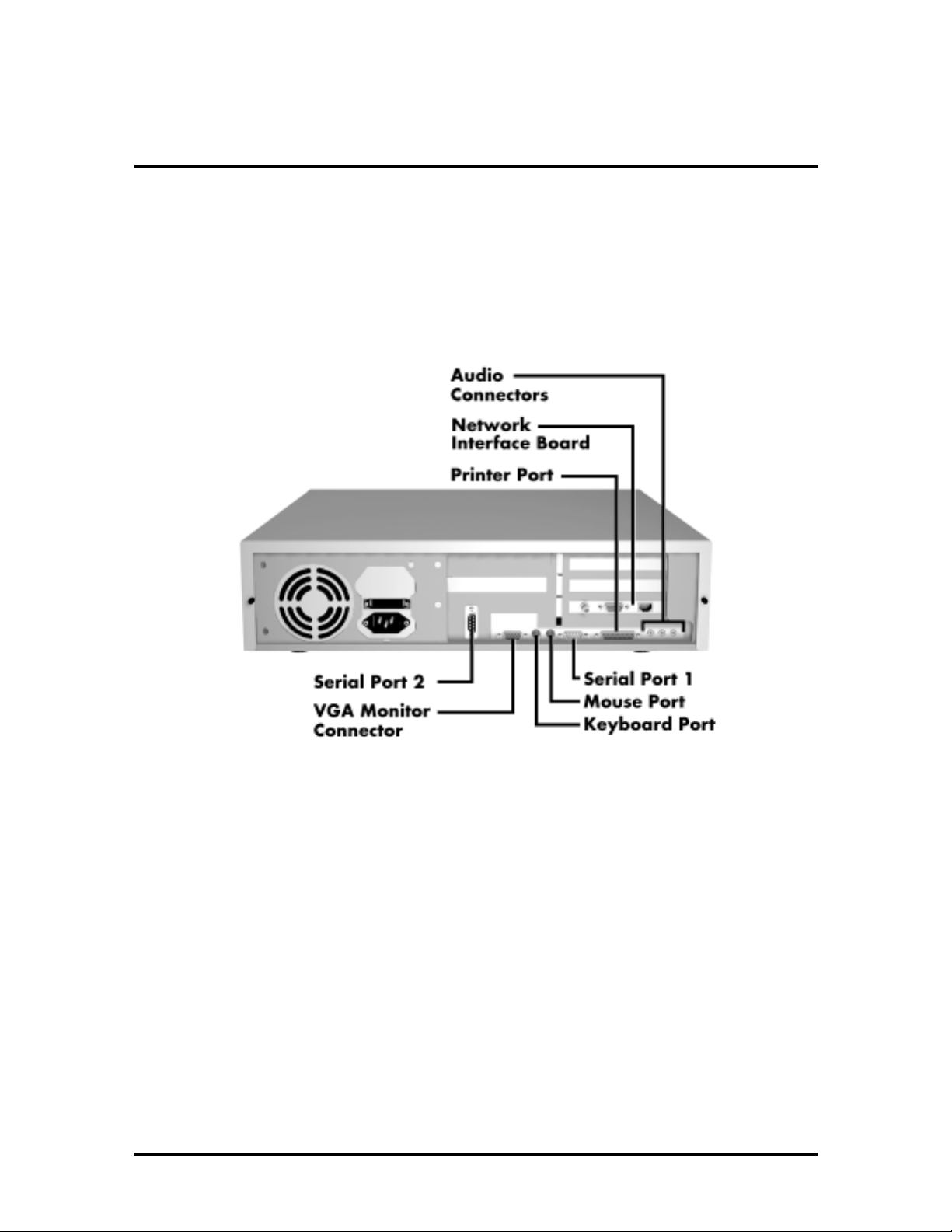
The following figure shows the location of the interface ports on the rear of the system unit
for configuring PowerMate Ve ETC Series hardware. Use the procedures described in
Section 2 of the PowerMate Ve Series Service and Reference Manual to set up the system
hardware.
Figure 2-1 Rear Panel I/O Ports
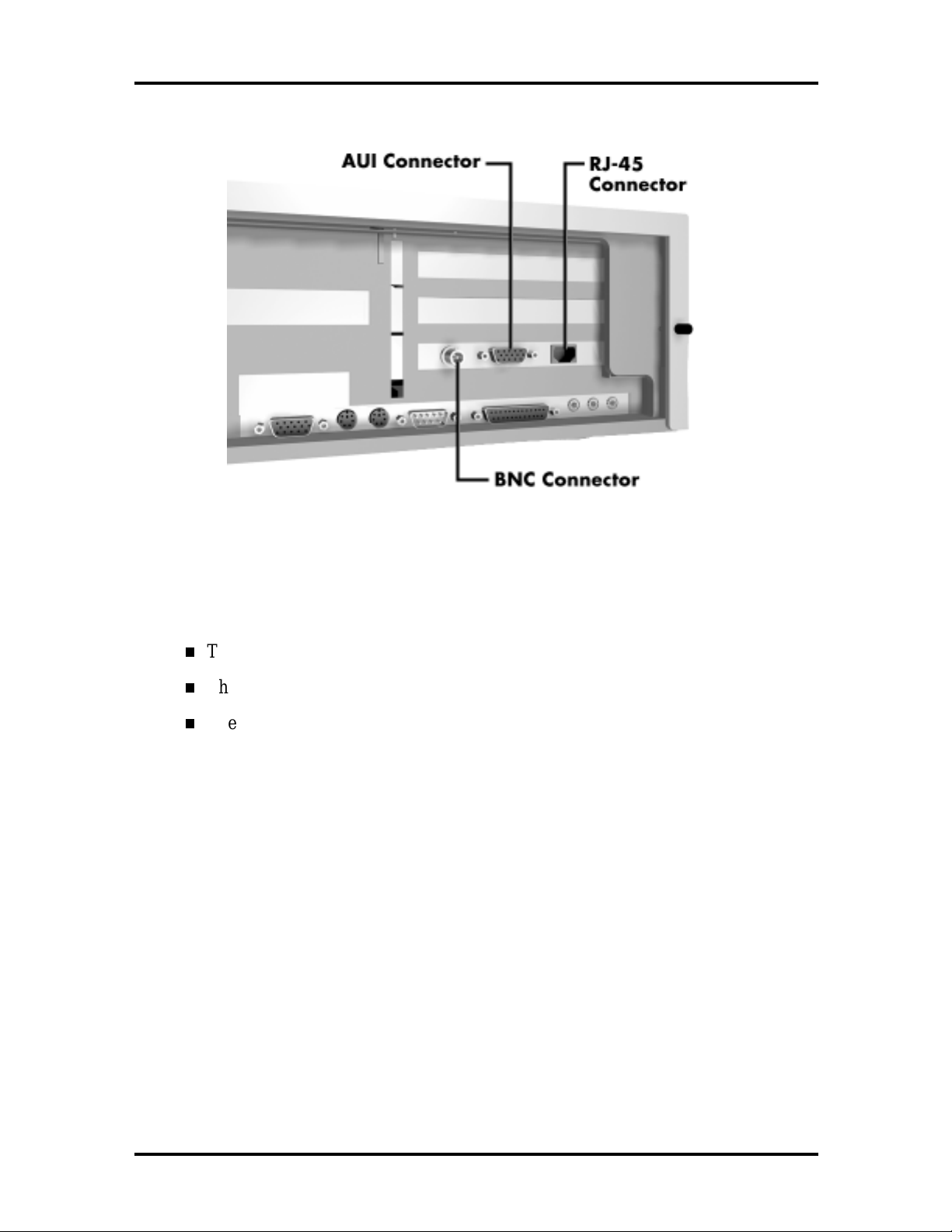
In addition, refer to the following figure for the location of the network interface board
connectors.
Page 14
2-2 Setup and Installation
Figure 2-2 Network Interface Board Connectors
The network board has connectors for coaxial and twisted-pair network cabling:
The BNC connector supports thin coaxial cables.
The AUI connector supports thick coaxial cables.
The RJ-45 connector supports twisted-pair 10BASE-T cables.
Connect the network cable to one of these connectors (depending on the type of network).
The PowerMate Ve ETC Series computer has Ethernet network drivers pre-loaded on the
hard disk.
Page 15

Section 3
Illustrated Parts Breakdown
This section contains updated parts lists and an exploded-view diagram for the
PowerMate Ve ETC Series system.
The information in this section applies to the following models:
ET-1830-24813E
ET-1830-24813CE
ET-1860-24813E
ET-1860-24813CE.
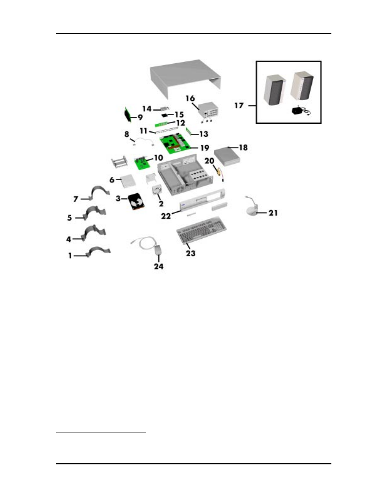
Table 3-1 lists the field-replaceable parts for the computer*. Figure 3-1 provides the
illustrated parts breakdown.
To order parts or obtain technical help, call 1-888-ETC-SUPT (1-888-382-7878).
* This data was prepared July 1997. For an up-to-date listing of spare parts, please call FaxFlash™ at
1-888-329-0088 (or 1-508-635-6090 outside the U.S.) and order document number 42181819.
Page 16

Illustrated Parts Breakdown 3-2
Table 3-1 PowerMate Ve ETC Series Field-Replaceable Parts List*
Item Description Part Number
1 Serial interface cable 158-050454-004
2 Fan assembly, 2-wire 158-050865-006
3 3 1/2-inch, 1.2-GB IDE hard disk,
WDAC21200
4 IDE signal cable, 3-connector 158-050562-008
5 Floppy drive signal cable,
3-connector
6 3-1/2 inch 1.44-MB diskette drive,
TEAC, DT
7 CD-ROM IDE signal cable,
2-connector (multimedia models only)
8 Audio cable, CD-ROM, 2-connector
(multimedia models only)
9 ISA/PCI backplane (desktop) 158-026204-000A
10 Network interface card (NIC) 158-050796-000
11a I/O plate without audio (non-
multimedia systems)
11b I/O plate with audio (multimedia
systems)
12 256 KB L2 Synchronous Pipeline
Burst Cache, 15 ns
158-050395-366
158-050503-002
158-050858-000
158-050562-004
158-050824-000
158-030782-003
158-030782-002
158-082737-015
13 8-MB EDO SIMM (2MB x 32) 158-082630-060
14 Heatsink w/clip 158-060324-001
15a 133-MHz Pentium processor
(PowerMate V133e ETC models)
15b 166-MHz Pentium processor
(PowerMate V166e ETC models)
16 Power supply, 145-watt,
(ASTEC-SA145-3495-717)
17 Speakers, 8-watt (multimedia models
only)
18 IDE CD-ROM reader (8-speed) CDR-1450A/BR
158-082502-016
158-082502-017
158-050730-000
158-050980-001
* This data was prepared July 1997. For an up-to-date listing of spare parts, please call FaxFlash™ at
1-888-329-0088 (or 1-508-635-6090 outside the U.S.) and order document number 42181819.
Page 17

Illustrated Parts Breakdown 3-3
Table 3-1 PowerMate Ve ETC Series Field-Replaceable Parts List*
Item Description Part Number
19a System board, without audio
158-056559-000
(non-multimedia systems)
19b System board, with audio (multimedia
158-056560-000
models)
20a Speaker assembly, internal 158-050685-003
21 Microphone (multimedia models only) 158-052116-000
22 Front bezel without IR (PowerMate
158-050992-000
V133e, V166, V166e models)
23 Keyboard, Chicony 158-052121-000
24 Mouse, PS/2-style 158-052115-000
* This data was prepared July 1997. For an up-to-date listing of spare parts, please call FaxFlash™ at
1-888-329-0088 (or 1-508-635-6090 outside the U.S.) and order document number 42181819.
Page 18
Illustrated Parts Breakdown 3-4
Figure 3-1 PowerMate Ve ETC Series Illustrated Parts Breakdown*
* This data was prepared July 1997. For an up-to-date listing of spare parts, please call FaxFlash™ at
1-888-329-0088 (or 1-508-635-6090 outside the U.S.) and order document number 42181819.
Page 19

Illustrated Parts Breakdown 3-5
Table 3-2 lists PowerMate Ve ETC Series documentation and packaging part numbers.
Table 3-2 PowerMate Ve ETC Series Documentation and Packaging*
Description Part Number
PowerMate Ve ETC Series User’s Guide
PowerMate Ve Series Service and Reference Manual
PowerMate Ve ETC Series Addendum to the PowerMate Ve Series
Service and Reference Manual
Corner blocks (requires 4) 158-040395-004
Shipping carton (multimedia) 158-040563-001
Shipping carton (non-multimedia) 158-040562-001
819-181780-000
819-181528-000
819-181819-000
* This data was prepared July 1997. For an up-to-date listing of spare parts, please call FaxFlash™ at
1-888-329-0088 (or 1-508-635-6090 outside the U.S.) and order document number 42181819.
Page 20

Index
C
Configurations, 1-1
D
Document
part number, 3-5
H
Hard disk specifications, 1-7
Help, 3-1
I
Illustrated parts breakdown, 3-1
Integrated graphics, 1-5
video memory, 1-5
resolutions and refresh rates, 1-5
Interrupts, 1-5
T
Technical help, 3-1
M
Memory, 1-2
N
Network interface board, 1-6
O
Option installation
SIMM upgrade, 1-2
checking system memory, 1-2
P
Packaging
part number, 3-5
S
SIMM upgrade, 1-2
Specifications, 1-9
System board
integrated graphics, 1-5
interrupts, 1-5
Support telephone number, 3-1
Page 21

(For United States Use Only)
FEDERAL COMMUNICATIONS COMMISSION
RADIO FREQUENCY INTERFERENCE STATEMENT
WARNING:
Changes or modifications to this unit not expressly approved by the party
responsible for compliance could void the user’s authority to operate the equipment.
NOTE:
Th is eq uip ment ha s be en t es t ed and fou nd t o co mp ly wit h t he limit s fo r a C lass B
dig ita l dev ice, pur su ant to Pa rt 15 of t he FCC Rule s. The se limit s a re des igne d t o p ro vid e
reasonable protection against harmful interference in a residential installation. This
equipment generates, uses and can radiate radio frequency energy and, if not installed and
used in accordance with the instructions, may cause harmful interference to radio
communications.
How e v e r , t her e is no g uara n tee t h a t in terfe ren c e will not o ccur in a p a rt icu la r in s ta lla tion. I f
this equipment does cause harmfu l interference to radio or televisio n reception, which can
be determined by turning the equipment off and on, the user is encouraged to t ry to co rrect
the interference by one or more of the following measures.
Reorient or relocate the receiving antenna.
Increase the separation between the equipment and receiver.
Connect the equipment to an outlet on a circuit differ ent from the o ne to which the
receiver is connected.
Use shielded and pro perly grounded I/O and power cables to ensure compliance of this unit
to the specified limits of the rules.
(For Canadian Use Only)
This Class B digital apparatus meets all requirements of the Canadian Interference-Causing
Equipment Regulations.
Cet appareil numérique de la classe B repecte toutes les exigences du Règlement sur le
matériel brouilleur du Canada.
Page 22

BATTERY REPLACEMENT
A lit hiu m ba tte ry in yo ur c omp u te r ma inta in s s ys te m c onfig ur a tion in for ma tion. I n the eve n t
t hat t he bat te ry fails to maint ain sys tem c onfig ura tio n info rmat ion , NE C re comme nds that
you replace the battery. See Chapter 4 in the PowerMate Ve Series Service and R eference
Manual for battery replacement information.
WARNING:
only with the same or equivalent type recommended by the manufacturer. Discard used
batteries according to the manufacturer’s instructions.
ATTENTION:
Remplacer uniquement avec une batterie du même type ou d’un type recommandé par le
constructeur. Mettre au rébut les batteries usagées conformément aux instructions du
fabricant.
There is a danger of explosion if the batt ery is incorrect ly replaced. Replace
Il y a danger d’explosion s’il y a replacement incorrect de la batterie.
BATTERY DISPOSAL
Do not place used batteries in your regular trash.
The nickel-cadmium or nickel metal-hydride batteries must be collected, recycled, or
disposed of in an environmentally-approved manner.
Th e inc iner at io n, lan dfilling , or mixing of b at t er ies wit h th e mu nicip al s o lid w as t e st r ea m is
prohibited by law
Return batteries to a federal or state approved battery recycler. This may be where
you purchased the batt ery o r a local seller of auto mo tive batteries. In MI NNESOTA, call
1-800-225-PRBA if further disposal information is required.
in most areas.
Contact your local waste management officials for other information regarding the
environmentally sound collection, recycling, and disposal of the batteries.
 Loading...