

Page 1

Page 2

The information in this document is subject to change without notice and does not represent a
commitment on the part of Native Instruments GmbH. The software described by this document is subject to a License Agreement and may not be copied to other media. No part of this
publication may be copied, reproduced or otherwise transmitted or recorded, for any purpose,
without prior written permission by Native Instruments GmbH, hereinafter referred to as Native
Instruments.
“Native Instruments”, “NI” and associated logos are (registered) trademarks of Native Instruments GmbH.
Mac, Mac OS, GarageBand, Logic, iTunes and iPod are registered trademarks of Apple Inc.,
registered in the U.S. and other countries.
Windows, Windows Vista and DirectSound are registered trademarks of Microsoft Corporation
in the United States and/or other countries.
All other trademarks are the property of their respective owners and use of them does not imply
any affiliation with or endorsement by them.
Document authored by: Jan Ola Korte
Software version: 1.1 (07/2018)
Disclaimer
Page 3

Contact
NATIVE INSTRUMENTS GmbH
Schlesische Str. 29-30
D-10997 Berlin
Germany
www.native-instruments.de
NATIVE INSTRUMENTS K.K.
YO Building 3F
Jingumae 6-7-15, Shibuya-ku,
Tokyo 150-0001
Japan
www.native-instruments.co.jp
NATIVE INSTRUMENTS FRANCE SARL
113 Rue Saint-Maur
75011 Paris
France
www.native-instruments.com
NATIVE INSTRUMENTS North America, Inc.
6725 Sunset Boulevard
5th Floor
Los Angeles, CA 90028
USA
www.native-instruments.com
NATIVE INSTRUMENTS UK Limited
18 Phipp Street
London EC2A 4NU
UK
www.native-instruments.co.uk
SHENZHEN NATIVE INSTRUMENTS COMPANY Limited
5F, Shenzhen Zimao Center
111 Taizi Road, Nanshan District, Shenzhen,
Guangdong
China
www.native-instruments.com
© NATIVE INSTRUMENTS GmbH, 2018. All rights reserved.
Page 4

Table of Contents
Table of Contents
1 Welcome to TRK-01 ..................................................................................................
2 Document Conventions ..............................................................................................
3 New in Version 1.1 ....................................................................................................
4 Using TRK-01 in KOMPLETE KONTROL ........................................................................
4.1 Opening TRK-01 in KOMPLETE KONTROL .................................................................................... 12
4.2 Exploring Factory Preset Files in KOMPLETE KONTROL ................................................................ 13
4.3 Saving and Loading User Preset Files in KOMPLETE KONTROL .................................................... 15
5 Using TRK-01 in REAKTOR 6 ......................................................................................
5.1 Opening TRK-01 in REAKTOR 6 ................................................................................................... 18
5.2 Exploring Factory Preset Files in REAKTOR 6 ............................................................................... 19
5.3 Saving and Loading User Preset Files in REAKTOR 6 .................................................................. 20
6 MIDI Control and Host Integration ...............................................................................
6.1 Switching Sound Variations and Patterns via MIDI ..................................................................... 23
6.2 Playing the Kick and the Bass via MIDI ...................................................................................... 24
6.3 Playing the Root Key via MIDI ..................................................................................................... 26
6.4 Automation and MIDI Control ...................................................................................................... 26
6.5 Routing Outputs in a Host .......................................................................................................... 27
7 Overview of TRK-01 ...................................................................................................
9
10
11
12
18
23
28
8 Header .....................................................................................................................
8.1 Copying, Pasting, and Clearing Elements ................................................................................... 31
8.2 Tuning Panel .............................................................................................................................. 33
8.3 Timing Panel .............................................................................................................................. 35
9 Kick Engine ..............................................................................................................
9.1 Main Area ................................................................................................................................... 37
9.2 Display Area ............................................................................................................................... 38
TRK-01 - MANUAL - 4
30
36
Page 5

9.3 Modulation Area ......................................................................................................................... 40
9.4 Sound Selector ............................................................................................................................41
9.5 Sound Browser ............................................................................................................................42
9.6 Layer Sections ............................................................................................................................ 44
9.7 Global Section ............................................................................................................................ 50
9.8 Envelope Sections .......................................................................................................................51
9.9 LFO+Noise Section ..................................................................................................................... 53
9.10 Modulation Routing .................................................................................................................... 56
9.6.1 Layer Mode Selector ................................................................................................... 45
9.6.2 Pitch Envelope ........................................................................................................... 46
9.6.3 Sample Mode ............................................................................................................. 46
9.6.4 Synth Mode ................................................................................................................ 48
9.6.5 Rumble Mode ............................................................................................................. 49
9.6.6 Noise Mode ................................................................................................................ 49
9.9.1 LFO+Noise Mode Selector .......................................................................................... 54
9.9.2 Slow, Fast, and Tempo Mode ..................................................................................... 55
9.9.3 Beat Mode ................................................................................................................. 55
10 Bass Engine ..............................................................................................................
Table of Contents
58
10.1 Main Area ................................................................................................................................... 59
10.2 Display Area ............................................................................................................................... 60
10.3 Modulation Area ......................................................................................................................... 62
10.4 Sound Selector ............................................................................................................................63
10.5 Sound Browser ............................................................................................................................64
10.6 Tuning Controls .......................................................................................................................... 66
10.7 Oscillator Section ....................................................................................................................... 67
10.7.1 Oscillator Mode Selector ............................................................................................ 68
TRK-01 - MANUAL - 5
Page 6

Table of Contents
10.8 Modifier Section ..........................................................................................................................74
10.9 Filter Section .............................................................................................................................. 79
10.10 Envelope Sections .......................................................................................................................81
10.11 LFO Section .................................................................................................................................83
10.12 Modulation Routing .................................................................................................................... 86
10.7.2 Sub Oscillator ............................................................................................................ 69
10.7.3 Classic Mode ............................................................................................................. 69
10.7.4 Super Mode ................................................................................................................ 70
10.7.5 West Mode ................................................................................................................. 71
10.7.6 FM Mode .................................................................................................................... 72
10.7.7 Modern Mode ............................................................................................................. 73
10.8.1 Modifier Mode Selector .............................................................................................. 75
10.8.2 Ring Mode ................................................................................................................. 76
10.8.3 Freq Mode .................................................................................................................. 77
10.8.4 Sine Mode .................................................................................................................. 78
10.8.5 S&H Mode .................................................................................................................. 78
10.9.1 Filter Mode Selector ................................................................................................... 80
10.9.2 Filter Key Tracking ..................................................................................................... 81
10.11.1 LFO Mode Selector ..................................................................................................... 84
10.11.2 Slow, Fast, and Tempo Mode ..................................................................................... 85
10.11.3 Beat Mode ................................................................................................................. 86
11 Kick Effects ..............................................................................................................
88
11.1 Main Area ................................................................................................................................... 89
11.2 Display Area ............................................................................................................................... 90
11.3 Insert Section ............................................................................................................................. 91
11.3.1 Insert Mode Selector .................................................................................................. 92
TRK-01 - MANUAL - 6
Page 7

Table of Contents
11.4 Equalizer Section ........................................................................................................................ 97
11.5 Output Section ............................................................................................................................99
11.3.2 Distort Mode .............................................................................................................. 93
11.3.3 S&H Mode .................................................................................................................. 94
11.3.4 Bit Redux Mode .......................................................................................................... 95
11.3.5 Lowpass Mode ........................................................................................................... 96
11.3.6 Highpass Mode .......................................................................................................... 96
12 Bass Effects ..............................................................................................................
12.1 Main Area ................................................................................................................................... 103
12.2 Display Area ............................................................................................................................... 104
12.3 Insert Section ............................................................................................................................. 106
12.4 Equalizer Section ........................................................................................................................ 110
12.5 Output Section ............................................................................................................................113
12.6 Ducking Envelope Section ........................................................................................................... 115
12.3.1 Insert Mode Selector .................................................................................................. 107
12.3.2 Distort Mode .............................................................................................................. 107
12.3.3 Unison Mode .............................................................................................................. 108
12.3.4 Flanger Mode ............................................................................................................. 109
12.3.5 Phaser Mode .............................................................................................................. 110
13 Sequencer ................................................................................................................
102
117
13.1 Kick Pattern Area ........................................................................................................................ 118
13.2 Kick Sequencer Lanes ................................................................................................................. 119
13.3 Bass Pattern Area .......................................................................................................................120
13.4 Bass Sequencer Lanes ................................................................................................................ 121
13.5 Using Step Locks ........................................................................................................................ 122
13.6 Using Parameter Focus ............................................................................................................... 124
TRK-01 - MANUAL - 7
Page 8

Table of Contents
14 Master ......................................................................................................................
14.1 Delay .......................................................................................................................................... 127
14.2 Reverb ........................................................................................................................................ 128
14.3 Bass Enhancer ........................................................................................................................... 129
14.4 Booster ....................................................................................................................................... 130
15 Troubleshooting ........................................................................................................
16 Credits ......................................................................................................................
126
131
133
TRK-01 - MANUAL - 8
Page 9

Welcome to TRK-01
1 Welcome to TRK-01
TRK-01 is an instrument for creating kick drums and bass sounds as the starting point and
foundation of your track. For this purpose, it combines the flexible KICK and BASS for sound
generation and processing with powerful sequencers that allow you to intuitively realize complex musical ideas.
The controls of the KICK and BASS are optimized for playability, offering smooth operation
and the maximum of sweet spots. Different modes for sections like the KICK’s Layers or the
BASS’s OSCILLATOR allow you to completely change the character of the sound in an instant.
The sequencers enhance classic step sequencing with advanced features like Step Locks and
Parameter Focus that allow you to bring a whole new layer of animation to your sounds. For
more information, refer to ↑13.5, Using Step Locks and ↑13.6, Using Parameter Focus.
The innovative global TUNING concept ensures that the KICK and the BASS are always in tune
with each other and additional elements in your track, allowing you to keep low-frequency content in check and match the key and scale of your project at all times. For more information,
refer to ↑8.2, Tuning Panel.
Smart sound design and mixing features like the Ducking Envelope of the BASS allow you to
fine-tune bass sounds in conjunction with your kick drum and interlace the two elements in
interesting ways. For more information, refer to ↑12.6, Ducking Envelope Section.
By fusing all of these features into an intuitive user interface, TRK-01 empowers you to create
the best possible foundation for your track in a playful manner. Enjoy!
TRK-01 - MANUAL - 9
Page 10
Document Conventions
2 Document Conventions
This document uses particular formatting to point out special facts and to warn you of potential issues. The icons introducing the following notes let you see what kind of information can
be expected:
The speech bubble icon indicates a useful tip that may often help you to solve a task more efficiently.
The exclamation mark icon highlights important information that is essential for the given context.
The red cross icon warns you of serious issues and potential risks that require your full attention.
Furthermore, the following formatting is used:
▪ Text appearing in (drop-down) menus (such as Open…, Save as… etc.) in the software and
paths to locations on your hard disk or other storage devices is printed in italics.
▪ Text appearing elsewhere (labels of buttons, controls, text next to checkboxes etc.) in the
software is printed in blue. Whenever you see this formatting applied, you will find the
same text appearing somewhere on the screen.
▪ Important names and concepts are printed in bold.
▪ References to keys on your computer’s keyboard you’ll find put in square brackets (e.g.,
“Press [Shift] + [Enter]”).
► Single instructions are introduced by this play button type arrow.
→ Results of actions are introduced by this smaller arrow.
TRK-01 - MANUAL - 10
Page 11

New in Version 1.1
3 New in Version 1.1
The following features and changes have been added to TRK-01 1.1:
▪ New Sound Browsers with Sound Presets for the KICK and the BASS allow you to quickly
mix and match sound presets within a Preset file. For more information, refer to ↑9.5,
Sound Browser and ↑10.5, Sound Browser.
▪ New KICK and BASS Sequencer Bypass buttons allow you to play the KICK and the BASS
externally using MIDI keyboards and sequencers. For more information, refer to ↑6.2, Play-
ing the Kick and the Bass via MIDI.
▪ New MIDI control over the global ROOT key allows you to transpose the KICK and BASS
Sequencers externally. For more information, refer to ↑6.3, Playing the Root Key via MIDI.
▪ New visual aids in the EQUALIZER displays show the fundamental frequency of the ROOT
key and its harmonics. For more information, refer to ↑11.4, Equalizer Section and ↑12.4,
Equalizer Section.
▪ New Step Lock Enable buttons in the KICK and BASS Sequencers allow you to enable or
disable the Step Locks in a sequence. For more information, refer to ↑13.1, Kick Pattern
Area and ↑13.3, Bass Pattern Area.
▪ New Offset Up and Down buttons in the BASS Sequencer allow you to shift the pitches of
all steps in the selected page up or down. For more information, refer to ↑13.3, Bass Pat-
tern Area.
▪ New Layer Enable buttons for LAYER A and LAYER B in the KICK allow you to switch the
Layers on or off. For more information, refer to ↑9.6, Layer Sections.
▪ New INVERT parameter in the KICK Layer’s SAMPLE mode allows you to invert the phase
of the loaded sample. For more information, refer to ↑9.6.3, Sample Mode.
▪ New individual stereo outputs for the DELAY and the REVERB send effects allow you to
process and mix the signals in your host. For more information, refer to ↑6.5, Routing Out-
puts in a Host.
▪ Fixed timing issues when switching patterns in certain hosts.
▪ Updated and improved manual covering the new features as well as adding more informa-
tion to a number of key sections.
TRK-01 - MANUAL - 11
Page 12
1
2
4
3
Using TRK-01 in KOMPLETE KONTROL
Opening TRK-01 in KOMPLETE KONTROL
4 Using TRK-01 in KOMPLETE KONTROL
TRK-01 is optimized to integrate with KOMPLETE KONTROL using Native Kontrol Standard
(NKS). You can explore Factory Preset files in the KOMPLETE KONTROL Browser, and control
the instrument using the KOMPLETE KONTROL keyboard.
The following sections explain how to open TRK-01 in KOMPLETE KONTROL, as well as explore Factory Preset files and use User Preset files.
For more information about controlling TRK-01 using the KOMPLETE KONTROL keyboard, refer to
↑6, MIDI Control and Host Integration.
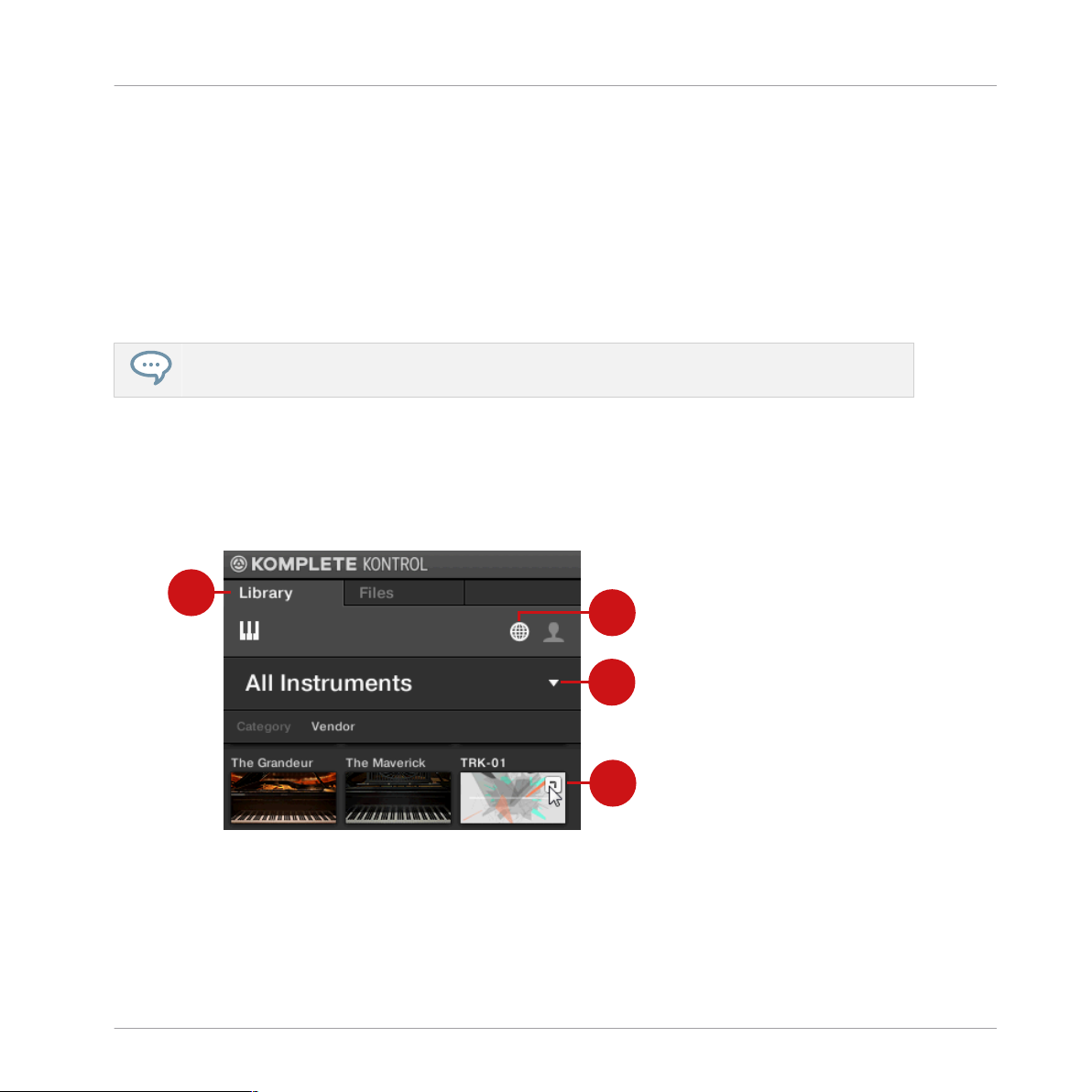
4.1 Opening TRK-01 in KOMPLETE KONTROL
To open TRK-01 in KOMPLETE KONTROL:
Opening TRK-01 in KOMPLETE KONTROL
1. Go to the Browser’s Library tab (1).
2. Select the factory content (2).
3. Open the Product selector by clicking on the arrow symbol (3).
TRK-01 - MANUAL - 12
Page 13
1
2
Using TRK-01 in KOMPLETE KONTROL
Exploring Factory Preset Files in KOMPLETE KONTROL
4. Find TRK-01 in the list of Native Instruments products.
5. Place the mouse over the TRK-01 entry and click on the arrow symbol that appears in the
upper right corner (4).
→ TRK-01 loads with its default Preset file.
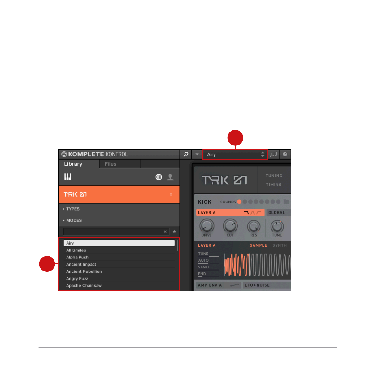
4.2 Exploring Factory Preset Files in KOMPLETE KONTROL
To explore Factory Preset files in KOMPLETE KONTROL:
Exploring Factory Preset files in KOMPLETE KONTROL
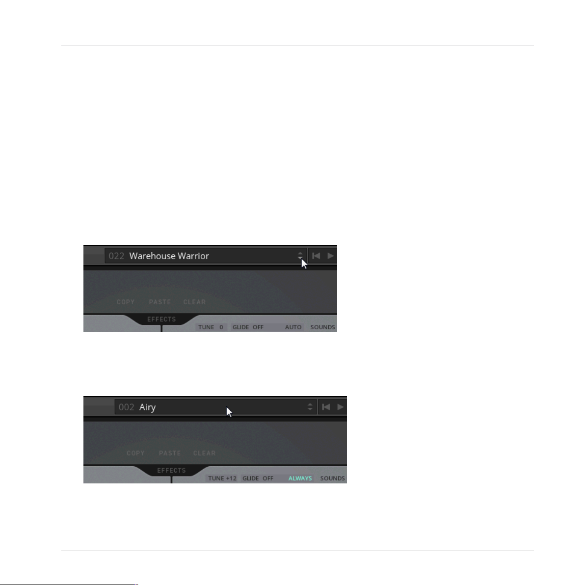
You can use the Preset display in KOMPLETE KONTROL’s Header to load Preset files.
► Click on the arrow buttons in the Preset display (1).
TRK-01 - MANUAL - 13
Page 14
Using TRK-01 in KOMPLETE KONTROL
Exploring Factory Preset Files in KOMPLETE KONTROL
→ The Preset files are loaded one after the other.
Alternatively, you can load Preset files from the Browser’s Results list and benefit from the
Prehear function. This allows you to listen to the preview of a Preset file before loading it.
► Click on an entry in the Results list (2) to select it.
→ The preview of the corresponding Preset file is played back (Prehear needs to be enabled
in KOMPLETE KONTROL).
► Double click on an entry in the Results list (2).
⇨ The corresponding Preset file is loaded.
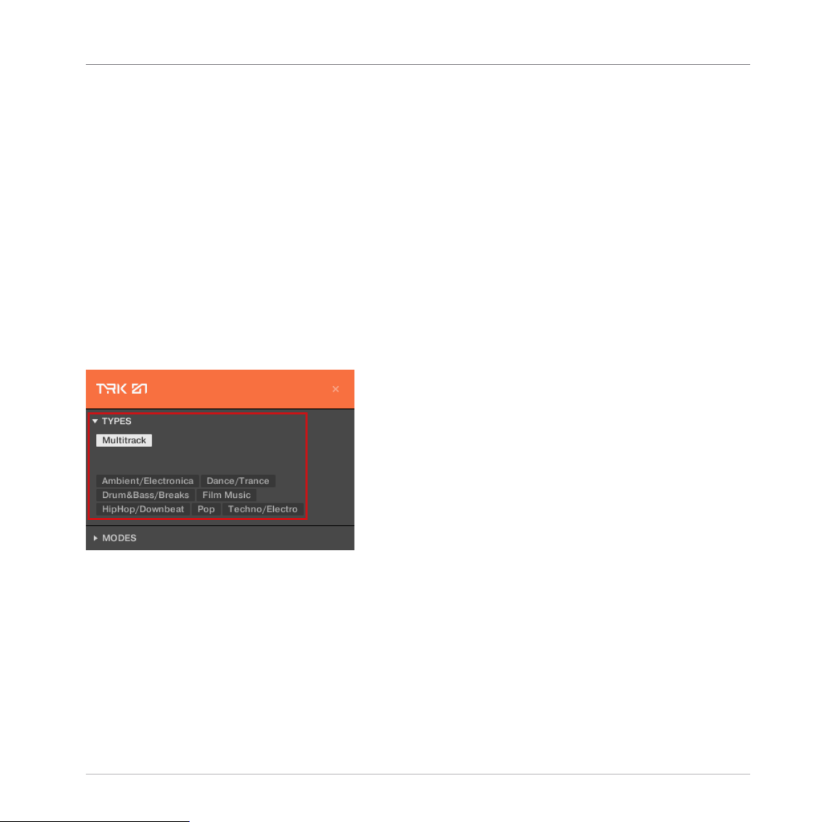
Filtering Results by Musical Genre
If you want to only explore Preset files that are associated with a particular musical genre, you
can do so by using the TYPES filter in the KOMPLETE KONTROL Browser.
The Types and Sub-Types for TRK-01
To filter the entries in the Browser’s Results list by musical genres:
1. Open the TYPES filter in the Browser.
2. Click on the Type Multitrack to show the available Sub-Types.
3. Click on one of the musical genres available as Sub-Types.
→ The Results list only shows Preset files associated with the selected musical genre.
TRK-01 - MANUAL - 14
Page 15
Using TRK-01 in KOMPLETE KONTROL
Saving and Loading User Preset Files in KOMPLETE KONTROL
4.3 Saving and Loading User Preset Files in KOMPLETE KONTROL
In order to permanently save all adjustments and settings made in TRK-01 including your
sound variations, combinations of sound presets, samples, and patterns, you need to save a
User Preset file.
▪ For more information about sound variations, refer to ↑9.4, Sound Selector and ↑10.4,
Sound Selector.
▪ For more information about sound presets, refer to ↑9.5, Sound Browser and ↑10.5, Sound
Browser.
▪ For more information about loading samples, refer to ↑9.6.3, Sample Mode.
▪ For more information about patterns, refer to ↑13.1, Kick Pattern Area.
Saving User Preset Files
To save a User Preset file:
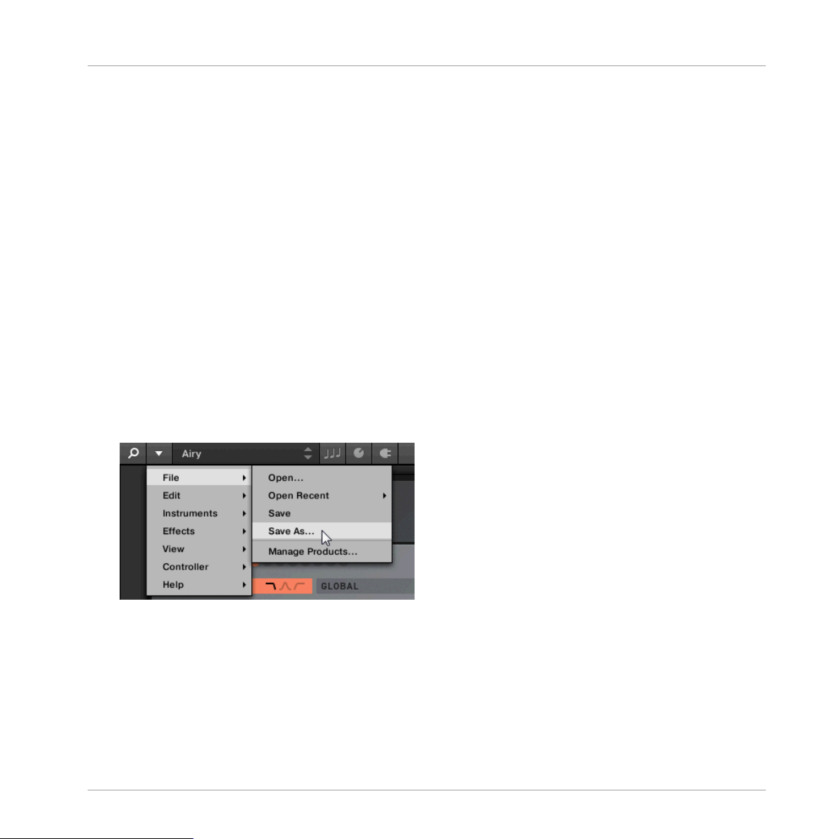
1. Select the entry Save As… in the File submenu of the KOMPLETE KONTROL menu.
TRK-01 - MANUAL - 15
Page 16
Using TRK-01 in KOMPLETE KONTROL
Saving and Loading User Preset Files in KOMPLETE KONTROL
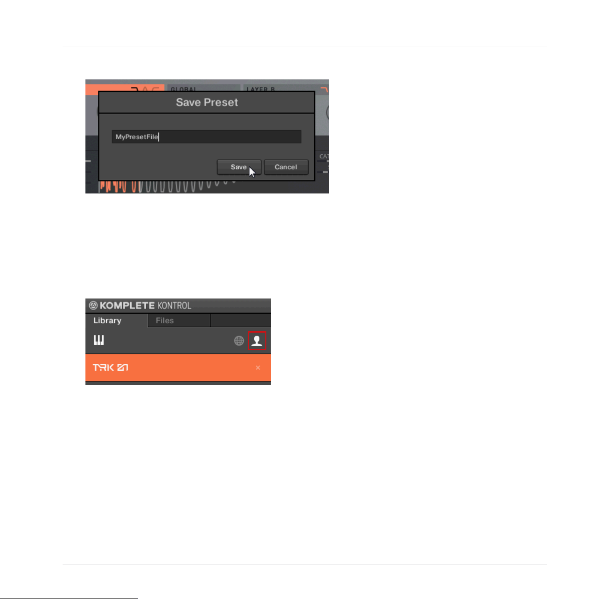
2. Enter a name for your User Preset file and click on Save in the Save Preset dialog.
→ Your User Preset file is saved.
Loading User Preset Files
To load a previously saved User Preset file:
1. Select the user content in the KOMPLETE KONTROL Browser and ensure that TRK-01 is
selected in the Product selector.
TRK-01 - MANUAL - 16
Page 17
Saving and Loading User Preset Files in KOMPLETE KONTROL
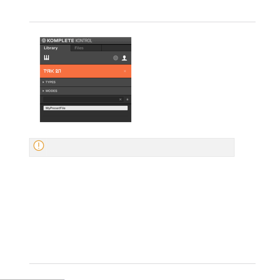
2. Find your User Preset file in the Results list and double-click on it.
Your User Preset file is loaded.
→
User Preset files saved in KOMPLETE KONTROL can also be loaded when using TRK-01 in REAKTOR 6. For more information about loading User Preset files in REAKTOR 6, refer to ↑5.3, Saving
and Loading User Preset Files in REAKTOR 6.
Using TRK-01 in KOMPLETE KONTROL
TRK-01 - MANUAL - 17
Page 18
1
2
3
4
Using TRK-01 in REAKTOR 6
Opening TRK-01 in REAKTOR 6
5 Using TRK-01 in REAKTOR 6
TRK-01 is a REAKTOR Ensemble that can be loaded in REAKTOR 6. This allows you to not
only play the instrument, but also combine it with other Ensembles, or dive into its Structure
to learn more about how it is built.
Information about using Ensembles and the Structure can be found in the REAKTOR 6 documentation.
The following sections explain how to open TRK-01 in REAKTOR 6, as well as explore Factory
Preset files and use User Preset files.
5.1 Opening TRK-01 in REAKTOR 6
To open TRK-01 in REAKTOR 6:
Opening TRK-01 in REAKTOR 6
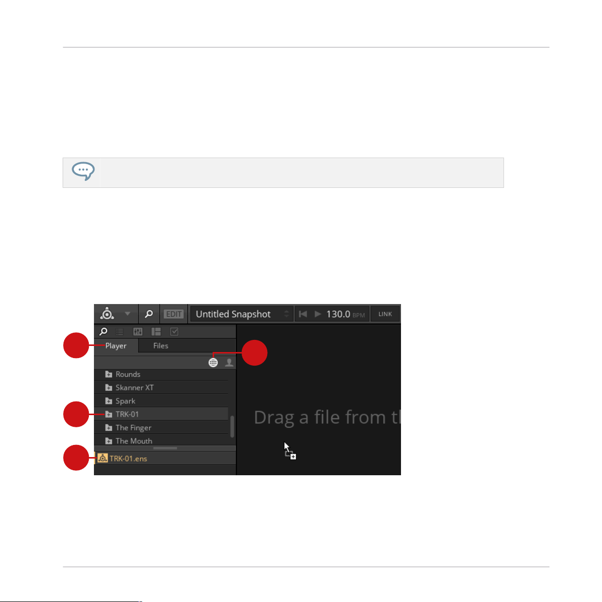
1. Go to the Browser’s Player tab (1).
2. Select the factory content (2).
TRK-01 - MANUAL - 18
Page 19
Using TRK-01 in REAKTOR 6
Exploring Factory Preset Files in REAKTOR 6
3. Find the TRK-01 folder (3) in the list of Native Instruments products and click on it.
4. Drag and drop TRK-01.ens (4) from the lower section of the Browser into REAKTOR’s
main area, or double-click on it.
→ TRK-01 loads with its default Preset file.
5.2 Exploring Factory Preset Files in REAKTOR 6
In REAKTOR 6, TRK-01’s Factory Preset files can be explored by loading Snapshots. The
Snapshots are identical to the corresponding Preset files in KOMPLETE KONTROL.
You can use the Snapshot menu in REAKTOR’s Toolbar to load Snapshots.
► Click on the arrow buttons in the Snapshot menu.
→ The Snapshots are loaded one after the other.
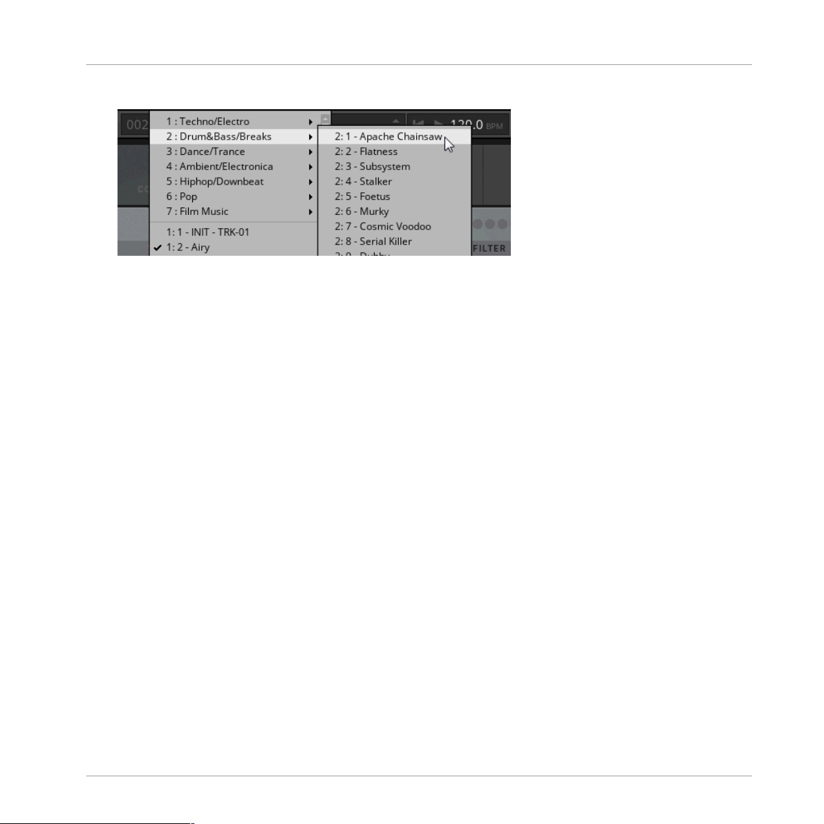
Alternatively, you can load Snapshots from a list that is organized in musical genres.
1. Click on the Snapshot menu in REAKTOR’s Toolbar.
TRK-01 - MANUAL - 19
Page 20
Using TRK-01 in REAKTOR 6
Saving and Loading User Preset Files in REAKTOR 6
2. Click on an entry in the list.
The corresponding Snapshot is loaded.
→
5.3 Saving and Loading User Preset Files in REAKTOR 6
In order to permanently save all adjustments and settings made in TRK-01 including your
sound variations, combinations of sound presets, samples, and patterns, you need to save a
User Preset file.
▪ For more information about sound variations, refer to ↑9.4, Sound Selector and ↑10.4,
Sound Selector.
▪ For more information about sound presets, refer to ↑9.5, Sound Browser and ↑10.5, Sound
Browser.
▪ For more information about loading samples, refer to ↑9.6.3, Sample Mode.
▪ For more information about patterns, refer to ↑13.1, Kick Pattern Area.
Saving User Preset Files
To save a User Preset file:
TRK-01 - MANUAL - 20
Page 21
Using TRK-01 in REAKTOR 6
Saving and Loading User Preset Files in REAKTOR 6
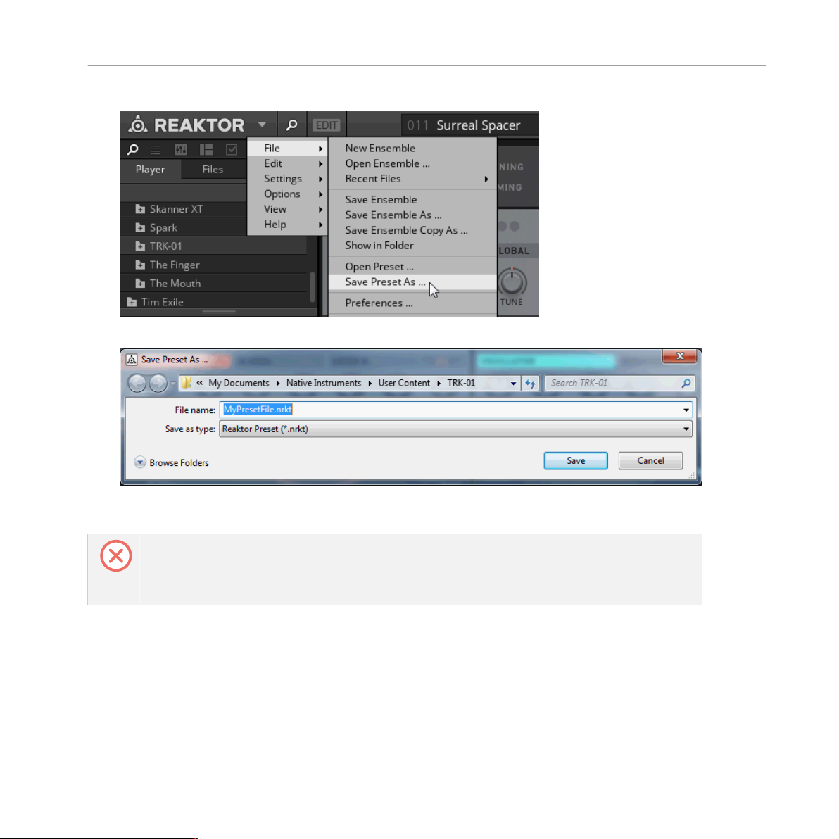
1. Select the entry Save Preset As … in the File submenu of the REAKTOR Main menu.
2. Enter a name for your User Preset file and click on
→ Your User Preset file is saved.
To ensure compatibility with KOMPLETE KONTROL, save the file into the following folder:
macOs: /Users/<user name>/Documents/Native Instruments/User Content/TRK-01
Windows: \Users\<user name>\Documents\Native Instruments\User Content\TRK-01
Loading User Preset Files
To load a previously saved User Preset file:
Save in the Save Preset As … dialog.
TRK-01 - MANUAL - 21
Page 22
Using TRK-01 in REAKTOR 6
Saving and Loading User Preset Files in REAKTOR 6
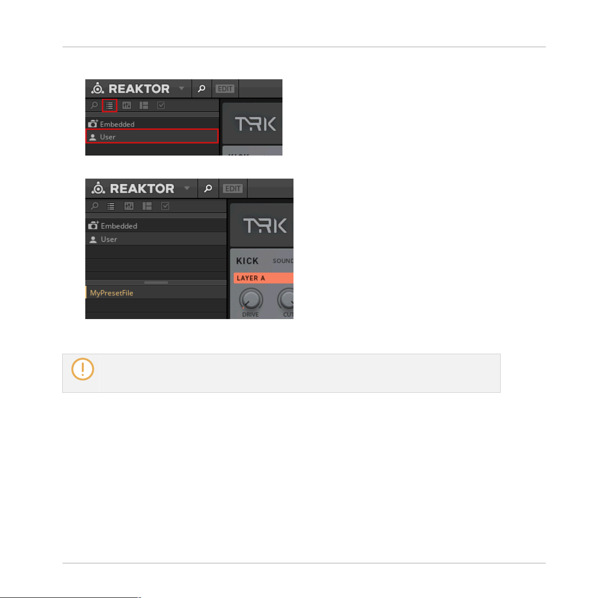
1. Select User in REAKTOR’s Preset Browser.
2. Find your User Preset file in the lower section of the Browser and double-click on it.
→ Your User Preset file is loaded.
User Preset files saved in REAKTOR 6 can also be loaded in KOMPLETE KONTROL. For more information about loading User Preset files in KOMPLETE KONTROL, refer to ↑4.3, Saving and Loading
User Preset Files in KOMPLETE KONTROL.
TRK-01 - MANUAL - 22
Page 23
MIDI Control and Host Integration
Switching Sound Variations and Patterns via MIDI
6 MIDI Control and Host Integration
You can control TRK-01 via MIDI to perform using standard MIDI keyboards and controllers.
This allows you to switch sound variations and patterns, play the global ROOT key or the KICK
and the BASS externally, and adjust instrument parameters remotely. TRK-01 is optimized for
use with the KOMPLETE KONTROL keyboards by supporting Native Kontrol Standard (NKS)
and the Light Guide.
The instrument integrates with your host by providing host automation of key controls and allowing you to use sequencers to control and play TRK-01 via MIDI. To facilitate full integration
into your host’s mixer, individual stereo outputs are available for the KICK, the BASS, as well
as the DELAY and the REVERB send effects.
6.1 Switching Sound Variations and Patterns via MIDI
You can use MIDI keyboards and sequencers to switch both sound variations saved in the
KICK’s and BASS’s Sound Selectors, as well as patterns of the KICK and BASS Sequencers.
The sound variations and patterns are switched by sending specific MIDI note messages to
TRK-01. When a MIDI note message is received, the switching occurs instantly.
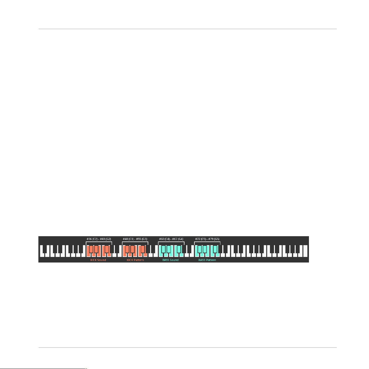
The MIDI note messages are mapped to the sound variations and patterns as shown in the following image:
Keyboard mapping for KICK and BASS sound variations and patterns
▪ You can switch the sound variations saved in the eight slots of the KICK’s Sound Selector
with MIDI notes # 36 (C2) to # 43 (G2).
▪ You can switch the eight patterns of the KICK Sequencer with MIDI notes # 48 (C3) to #
55 (G3).
TRK-01 - MANUAL - 23
Page 24
MIDI Control and Host Integration
Playing the Kick and the Bass via MIDI
▪ You can switch the sound variations saved in the eight slots of the BASS’s Sound Selector
with MIDI notes # 60 (C4) to # 67 (G4).
▪ You can switch the eight patterns of the BASS Sequencer with MIDI notes # 72 (C5) to #
79 (G5).
On KOMPLETE KONTROL keyboards, the keys corresponding to the correct MIDI note messages for
switching sound variations and patterns are highlighted in orange (for the KICK) and green (for the
BASS) by using the Light Guide.
6.2 Playing the Kick and the Bass via MIDI
You can play the KICK and the BASS externally using MIDI keyboards and sequencers, which
allows you to integrate TRK-01 into your performance or sequencing setup in a flexible manner. In order to do this, you have to bypass the KICK and BASS Sequencers.
Bypassing the Kick and Bass Sequencers
The KICK and BASS Sequencers can be bypassed independently. This way you can choose
whether you want to play both the KICK and the BASS via MIDI or either one of them, allowing
you to switch sound variations and patterns for the other. For more information about switching
sound variations and patterns for the KICK and the BASS, refer to ↑6.1, Switching Sound Var-
iations and Patterns via MIDI.
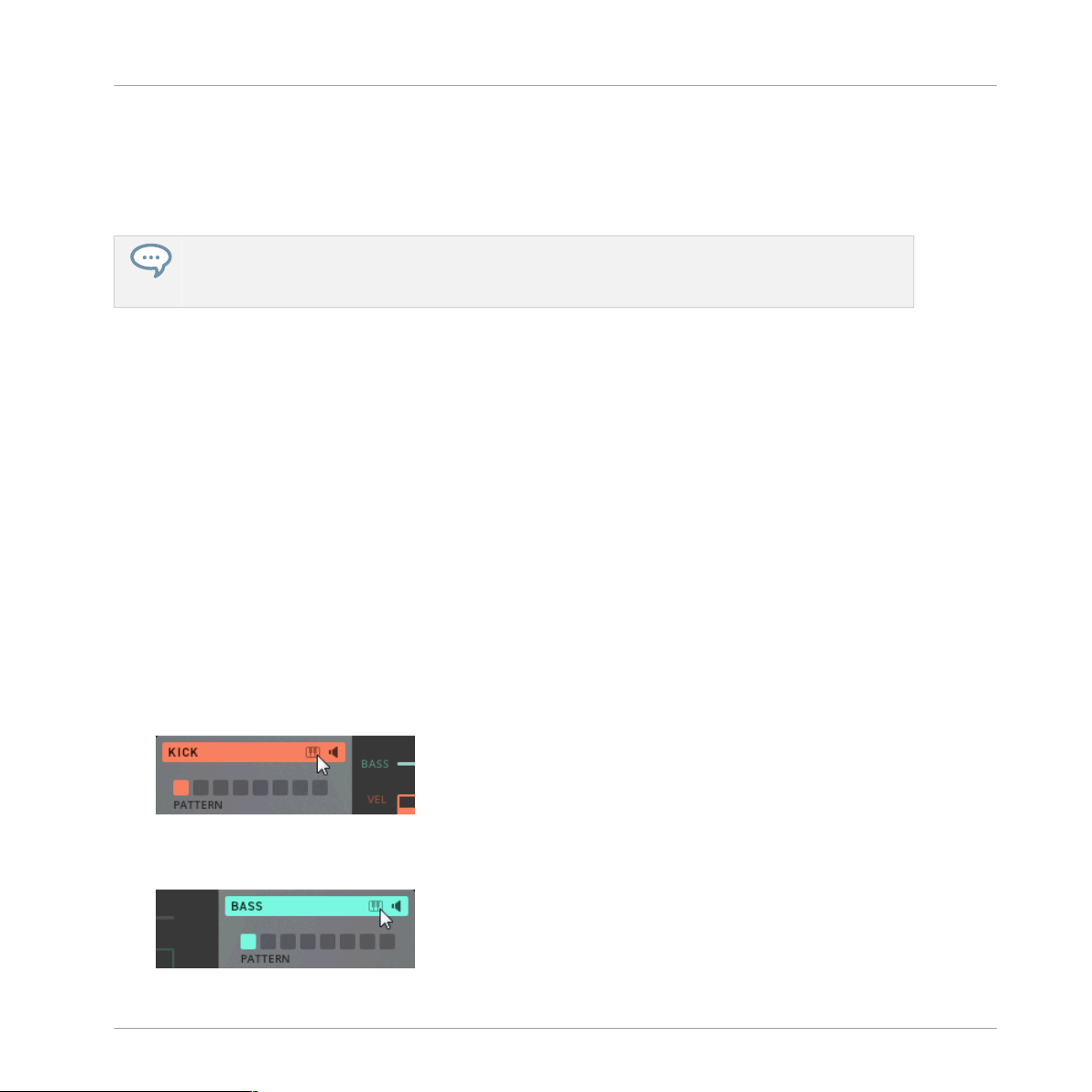
To bypass the KICK Sequencer and play the KICK via MIDI:
► Click on the KICK Sequencer Bypass button in the header of the pattern area.
To bypass the BASS Sequencer and play the BASS via MIDI:
► Click on the BASS Sequencer Bypass button in the header of the pattern area.
TRK-01 - MANUAL - 24
Page 25
MIDI Control and Host Integration
Playing the Kick and the Bass via MIDI
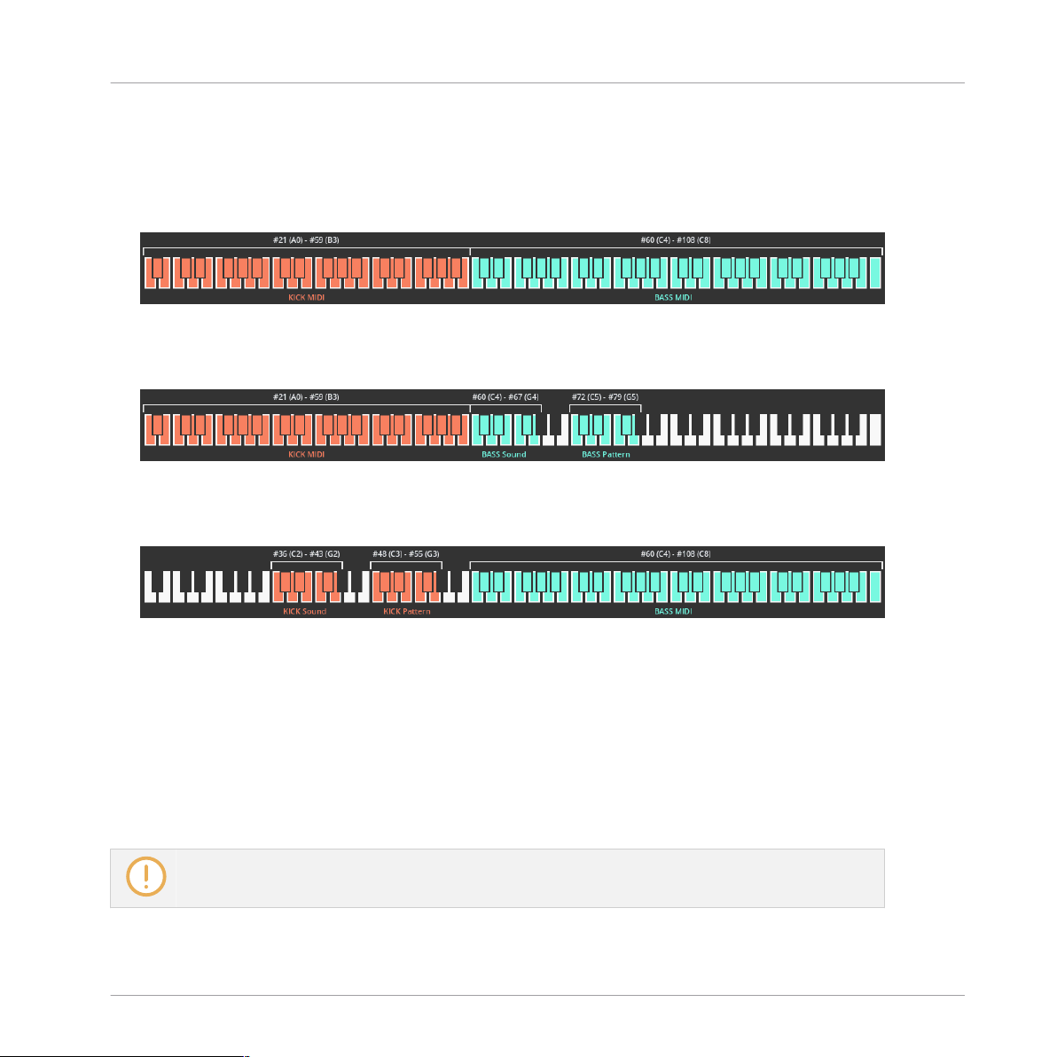
Configurations for MIDI Control
The following configurations for controlling TRK-01 via MIDI are possible:
▪ KICK and BASS Sequencer Bypass buttons enabled: You can play the KICK with MIDI notes
#21 (A0) to #59 (B3) and the BASS with MIDI notes #60 (C4) to #108 (C8):
▪ KICK Sequencer Bypass button enabled, BASS Sequencer Bypass button disabled: You can
play the KICK with MIDI notes #21 (A0) to #59 (B3) and switch sound variations and patterns for the BASS:
▪ KICK Sequencer Bypass button disabled, BASS Sequencer Bypass button enabled: You can
play the BASS with MIDI notes #60 (C4) to #108 (C8) and switch sound variations and
patterns for the KICK:
Output Transposition
In order to provide you with a meaningful range of pitches when playing the KICK and the
BASS externally, the MIDI note information is transposed in the following way:
▪ Playing the KICK in the given input range of MIDI notes #21 (A0) to #59 (B3) produces
pitches in the range of MIDI notes #9 (A-1) to #47 (B2).
▪ Playing the BASS in the given input range of MIDI notes #60 (C4) to #108 (C8) produces
pitches in the range of MIDI notes #24 (C1) to #72 (C5).
Note that in order for these ranges to apply, the TUNE controls on the KICK and the BASS need to
be set to 0.
TRK-01 - MANUAL - 25
Page 26
MIDI Control and Host Integration
Playing the Root Key via MIDI
6.3 Playing the Root Key via MIDI
You can play the global ROOT key via MIDI in order to transpose the KICK and BASS Sequencers on the fly or program key changes in the host.
► To play the global ROOT key via MIDI send MIDI note events to TRK-01 on MIDI channel
16.
→ The global ROOT key is set to the respective pitch when a MIDI note event is received.
If you want to transpose only the BASS but not the KICK, ensure that KICK TO ROOT in the Header’s TUNING panel is disabled. This way the pitch of the KICK is independent from the global
ROOT key.
6.4 Automation and MIDI Control
TRK-01 allows for host automation and MIDI control of key controls. This enables you to perform using standard MIDI controllers and use the automation features of your host to take control over TRK-01.
The following controls are enabled for automation and MIDI control in a host:
▪ All controls in the Main and Modulation areas of the KICK and BASS.
▪ The KICK and BASS Level faders and the KICK and BASS Enable buttons in the MASTER
Effects.
▪ The DELAY, REVERB, BASS Enhancer, and BOOSTER Enable buttons in the MASTER Ef-
fects.
Since TRK-01 supports Native Kontrol Standard (NKS), all enabled controls are automatically mapped to KOMPLETE KONTROL keyboards and MASCHINE controllers.
TRK-01 - MANUAL - 26
Page 27
MIDI Control and Host Integration
Routing Outputs in a Host
6.5 Routing Outputs in a Host
In addition to its main stereo output, TRK-01 also offers individual stereo outputs for the
KICK, the BASS, as well as the DELAY and the REVERB send effects. This allows you to proc-
ess and mix the signals in your host.
The KICK and BASS outputs are directly fed by the OUTPUT sections of the KICK and BASS
and are unaffected by settings made in the MASTER Effects.
The additional outputs are reported to the host by KOMPLETE KONTROL and REAKTOR 6 and
can be routed depending on the used host software.
For information about routing additional outputs of plug-ins in your host, refer to the host’s product
documentation.
TRK-01 - MANUAL - 27
Page 28
1
2
3
Overview of TRK-01
7 Overview of TRK-01
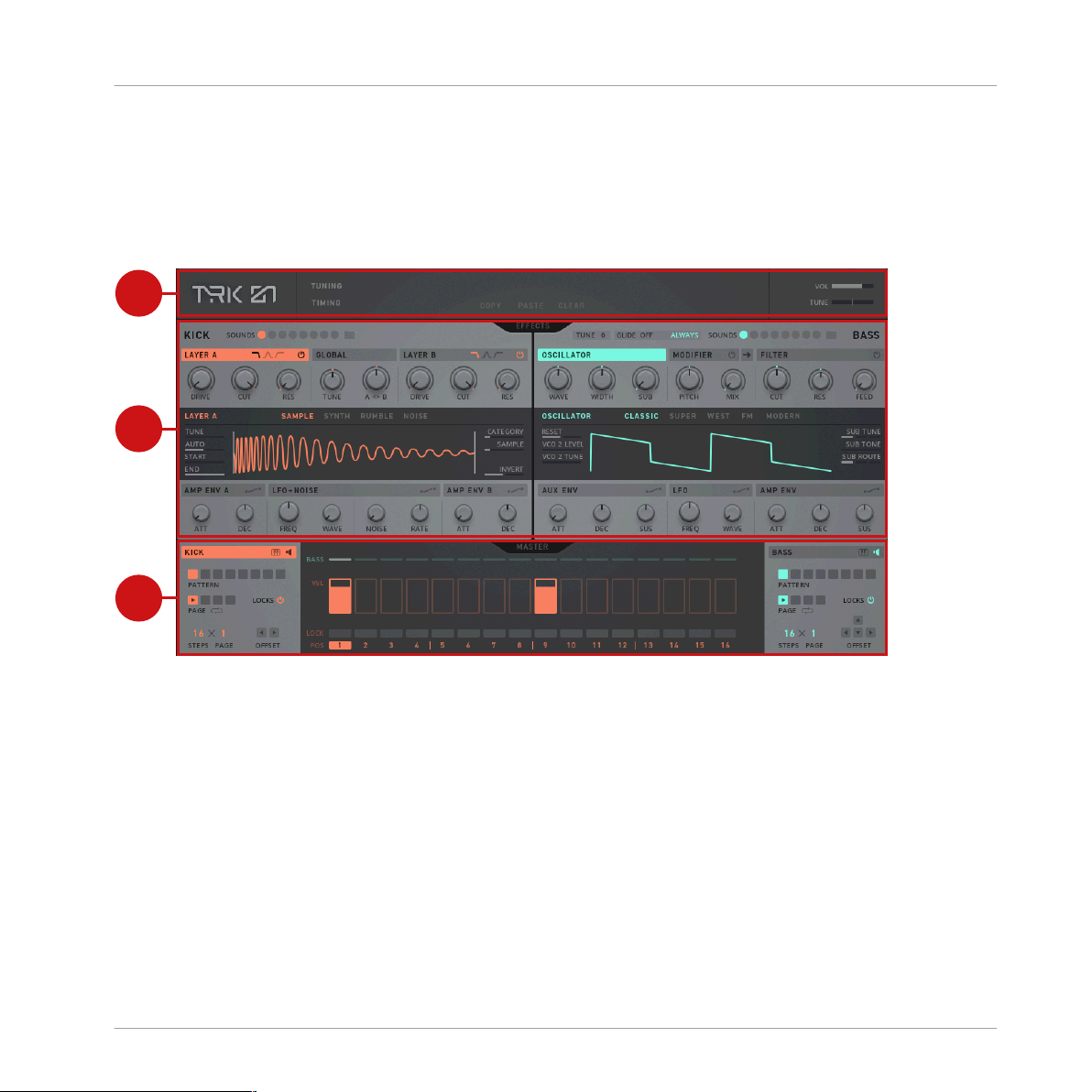
TRK-01 consists of three main sections that structure the instrument’s functionality in a logical and intuitive way:
Overview of TRK-01
(1) Header: The first main section provides global settings related to the tuning and timing of
the instrument, and facilitates the instrument’s workflows for copying, pasting, and clearing
the contents of elements in the user interface.
▪ For more information about the Header, refer to ↑8, Header.
▪ For more information about copying, pasting, and clearing elements, refer to ↑8.1, Copy-
ing, Pasting, and Clearing Elements.
TRK-01 - MANUAL - 28
Page 29

Overview of TRK-01
(2) Engines / Effects: The second main section hosts the sound generation and processing of the
KICK and BASS. The KICK features extensive possibilities to sculpt any kick drum sound
imaginable, and the BASS allows you to create a wide range of bass sounds. The central EF-
FECTS button toggles between the Engines for the sound generation, and the Effects for the
processing.
▪ For more information about the KICK and BASS Engines, refer to ↑9, Kick Engine and ↑10,
Bass Engine.
▪ For more information about the KICK and BASS Effects, refer to ↑11, Kick Effects and
↑12, Bass Effects.
(3) Sequencer / Master: The third main section comprises the KICK and BASS Sequencers and
the MASTER Effects. The KICK and BASS Sequencers allow you to quickly realize musical
ideas for the KICK and the BASS, while the MASTER Effects provide the means to enhance
and finalize the instrument’s output. The central MASTER button toggles between the KICK
and BASS Sequencers and the MASTER Effects.
▪ For more information about the KICK and BASS Sequencers, refer to ↑13, Sequencer.
▪ For more information about the MASTER Effects, refer to ↑14, Master.
TRK-01 - MANUAL - 29
Page 30

8 Header
1 2
3 5
6
7
4
The Header at the top of the TRK-01 user interface provides global settings related to the tuning and timing of the instrument, and facilitates the instrument’s workflows for copying, pasting, and clearing the contents of elements in the user interface.
The Header
(1) TRK-01 logo: Shows the instrument's credits.
(2) TUNING: Shows or hides the TUNING panel with settings for the global ROOT key and the
Quantizer of the instrument. For more information, refer to ↑8.2, Tuning Panel.
Header
(3) TIMING: Shows or hides the TIMING panel with settings for the tempo and the groove of
the instrument. For more information, refer to ↑8.3, Timing Panel.
(4) Focus View: Shows the selected element in the user interface. This element can be used
with the COPY, PASTE, and CLEAR buttons. For more information, refer to ↑8.1, Copying,
Pasting, and Clearing Elements.
(5) COPY / PASTE / CLEAR: These buttons are used to copy, paste, and clear the contents of
selected elements in the user interface, including the slots of the Sound Selectors as well as
the KICK and BASS Sequencer’s patterns, pages and Step Locks. For more information, refer
to ↑8.1, Copying, Pasting, and Clearing Elements.
(6) VOL slider: Adjusts the instrument’s output level in a range of -32 dB to +12 dB. The 0 dB
position is indicated by a fine line.
(7) TUNE slider: Adjusts the instrument’s global tuning in a range of -100 to +100 cents. The
0 cent position is in the center and indicated by a fine line.
TRK-01 - MANUAL - 30
Page 31

Copying, Pasting, and Clearing Elements
8.1 Copying, Pasting, and Clearing Elements
TRK-01 provides a workflow for copying, pasting, and clearing the contents of elements in the
user interface. The following elements can be used with this workflow:
▪ Slots of the Sound Selector in the KICK and BASS. For more information, refer to ↑9.4,
Sound Selector and ↑10.4, Sound Selector.
▪ Patterns and pages in the KICK and BASS Sequencers. For more information, refer to
↑13.1, Kick Pattern Area.
▪ Step Locks in the KICK and BASS Sequencers. For more information, refer to ↑13.5, Using
Step Locks.
Header
To permanently save the contents of elements in the user interface, you need to save them as part
of a User Preset file. For more information, refer to ↑4.3, Saving and Loading User Preset Files in
KOMPLETE KONTROL and ↑5.3, Saving and Loading User Preset Files in REAKTOR 6.
Copying and Pasting Elements
▪ To copy and paste the contents of elements in the user interface:
TRK-01 - MANUAL - 31
Page 32

Copying, Pasting, and Clearing Elements
1. Select the element you want to copy content from, in this example the first slot of the
BASS’s Sound Selector. The name of the selected element is shown in the Focus View of
the Header.
2. Click on COPY in the Header to copy the contents of the selected element to the clipboard.
3. Select the element you want paste the contents of the clipboard to, in this example the
fifth slot of the BASS’s Sound Selector. The name of the selected element is shown in the
Focus View of the Header.
Header
4. Click on PASTE in the Header to paste the contents of the clipboard to the selected element.
→ The contents of the first element are copied to the second element.
Clearing Elements
To clear the contents of elements in the user interface:
TRK-01 - MANUAL - 32
Page 33

1. Select the element you want to clear, in this example the first slot of the BASS’s Sound
Selector. The name of the selected element is shown in the Focus View of the Header.
2. Click on CLEAR in the Header to clear the contents of the selected element.
8.2 Tuning Panel
The TUNING panel provides settings related to the global tuning of TRK-01, allowing you to
match the key of other elements in your track and conveniently change the musical scale of
Preset files.
The global ROOT key is at the core of TRK-01’s tuning scheme. All tuning settings throughout
the instrument relate to this base pitch and are set as offsets in semitones. This means that
you can globally change the key of your project while preserving not only the intervals in your
sequences, but also the relationship between the pitch of the KICK and the BASS.
Header
Tuning Panel
The central Quantizer processes the output of the BASS Sequencer and forces all pitches to a
musical scale. In addition to selecting from a number of built-in scales, you can create your
own custom scales in the Quantizer’s Scale Editor.
The GLOBAL option allows you to preserve settings made in the TUNING panel when switching
Preset files. This allows you to match the scale and key your track and keep these settings in
place while exploring Preset files.
The KICK TO ROOT option locks the tuning of the KICK to the global ROOT key of the instrument. This allows you to maintain the pitch relationship of the KICK and the BASS while still
being able to change the key of your track.
If you enable KICK TO ROOT and set the KICK’s global TUNE control as well as the TUNE parameters of both LAYER A and LAYER B to 0, the KICK’s fundamental frequency will always match the
base pitch of the BASS. In many cases, this makes the low-frequency content of your track more
solid.
TRK-01 - MANUAL - 33
Page 34

3
1
5
4
2
6 7
8
9
The TUNING panel
(1) ROOT: Sets the global ROOT key for the instrument in semitone steps. All tuning settings
in TRK-01 relate to this base pitch.
(2) OCT: Sets the global ROOT key in octave steps.
(3) Quantizer Enable button: Switches the Quantizer on or off.
(4) Scale selector: Shows the selected scale of the Quantizer and allows you to select an entry
from the selection of built-in scales by clicking on the left and right arrow buttons.
(5) Scale Editor: Shows the contents of the selected scale and allows you to create your own
custom scale for the Quantizer by selecting different notes. The black dot highlights the global
ROOT key.
Header
Tuning Panel
(6) Scale Browser button: Shows the Scale Browser with the built-in scales for the Quantizer:
The scales are organized into two pages, which you can select by clicking on the left and right
arrow buttons.
(7) KICK TO ROOT: Locks the tuning of the KICK to the global ROOT key of the instrument.
(8) GLOBAL: Toggles between the Quantizer settings saved in Preset Files and the global
Quantizer settings.
(9) EXIT: Exits the TUNING panel.
TRK-01 - MANUAL - 34
Page 35

8.3 Timing Panel
1
5
3
2
4 86 7
The TIMING panel provides settings related to the global clock and rhythm of TRK-01, allowing you to not only set the tempo or synchronize the instrument to the host (SYNC), but also
create interesting rhythms by changing the Clock Division, switching the TIMING to TRIPLETS,
or adding a freely adjustable amount of SWING and GROOVE.
The TIMING panel
(1) Tempo: Sets the tempo of the instrument’s clock in BPM. When SYNC is enabled, the instrument is synchronized to the host clock and Tempo shows the host's BPM value.
Header
Timing Panel
(2) SYNC: Synchronizes the instrument’s clock to the host clock.
(3) Clock Division: Sets the clock division of the KICK and BASS Sequencers to either 8th
notes (1/8) or 16th notes (1/16).
(4) Timing Division: Sets the rhythm of the KICK and BASS Sequencers to either a STRAIGHT
or TRIPLET.
(5) Timing Display: Shows the settings made with SWING and GROOVE in relation to the basic
clock.
(6) SWING: Adjusts the amount of swing applied to the clock.
(7) GROOVE: Adjusts the amount of rhythmic variation applied to the clock when SWING is
used.
(8) EXIT: Exits the TIMING panel.
TRK-01 - MANUAL - 35
Page 36

9 Kick Engine
1
2
3
The KICK Engine features extensive possibilities to sculpt any kick drum sound imaginable
and seamlessly integrates with the BASS Engine to provide a solid foundation for your track.
It couples sampling and synthesizer techniques in a basic structure: Two independent Layer
sections including distortion and resonant filters, LAYER A and LAYER B, are combined in the
GLOBAL section.
The KICK Engine’s controls are optimized to provide smooth transitions between timbres, with
focused parameter ranges that produce the maximum of sweet spots. The different modes of
the LAYER A and LAYER B sections allow you to completely change the character of the KICK
Engine on the fly.
The KICK Engine consists of three interface sections:
Kick Engine
Overview of the KICK Engine
(1) Main area: Offers tuning settings, the Sound Selector for sound variations, and key controls
that allow you to shape your sound. The controls are organized into three sections: LAYER A,
GLOBAL, LAYER B. For more information, refer to ↑9.1, Main Area.
TRK-01 - MANUAL - 36
Page 37

(2) Display area: Provides visual feedback and facilitates in-depth editing of additional parame-
1
2 3 4
ters for each section of the KICK Engine, and gives you access to the Modulation Routing. For
more information, refer to ↑9.2, Display Area.
(3) Modulation area: Offers immediate control over key parameters that allow you to shape how
your sound changes over time. The controls are organized into three sections: AMP ENV A, LFO
+NOISE, AMP ENV B. For more information, refer to ↑9.3, Modulation Area.
9.1 Main Area
In addition to the Sound Selector for sound variations, the Main area provides control over the
distortion effect (DRIVE) and filter of the two Layers (LAYER A, LAYER B), as well as a global
tuning control and a crossfade control to set the level balance between them (GLOBAL). This
not only allows you to quickly adapt Presets files to your needs, but also perform with sounds
in an intuitive way by changing key controls on the fly.
Additional parameters for each section in the Main and Modulation areas can be accessed in the
Display area by clicking on the respective section’s header. For more information, refer to ↑10.2,
Display Area
Kick Engine
Main Area
The Main area consists of the following sections:
The KICK Engine's Main area
TRK-01 - MANUAL - 37
Page 38

(1) Sound Selector and Browser: The eight slots of the Sound Selector allow you to save and re-
1
232
call sound variations for the KICK or load any of the sound presets included in the dedicated
Sound Browser. For more information, refer to ↑9.4, Sound Selector and ↑9.5, Sound Browser.
(2) LAYER A: The first of two independent Layer sections has three controls in the Main area
that allow you to define the basic character of the sound. The first control adjusts the amount
of DRIVE, or distortion, while the second and third control are dedicated to LAYER A’s filter.
For more information, refer to ↑9.6, Layer Sections.
(3) GLOBAL: This central section has two controls in the Main area that allow you to control
the tuning and mix of the KICK Engine. The first control adjusts the tuning, while the second
control blends between LAYER A and LAYER B. For more information, refer to ↑9.7, Global
Section.
(4) LAYER B: The second of two independent Layer sections has three controls in the Main
area that allow you to define the basic character of the sound. The first control adjusts the
amount of DRIVE, or distortion, while the second and third control are dedicated to LAYER B’s
filter. For more information, refer to ↑9.6, Layer Sections.
9.2 Display Area
The Display area provides visual feedback for the selected section in the Main and Modulation
areas of the KICK Engine and offers additional parameters that allow you to build your own
sounds from scratch and fine-tune Preset files.
Kick Engine
Display Area
The KICK Engine 's Display area
TRK-01 - MANUAL - 38
Page 39

(1) Mode selector: Allows you to change the character of the selected section by choosing from
a number of different modes. For example, this includes different sampling or synthesizer
techniques for LAYER A and LAYER B, or a variety of synchronization options for LFO+NOISE.
(2) Additional parameters: Allow you to fine-tune settings related to the selected section. For example, this includes detailed settings for LAYER A’s and LAYER B’s LAYER modes and Pitch
Envelopes, or additional options for the envelopes, AMP ENV A and AMP ENV B.
(3) Display: Provides visual feedback while you adjust the controls of the selected section. For
example, this includes the waveform of LAYER A, LAYER B, and LFO+NOISE, or the shape of
the envelopes, AMP ENV A and AMP ENV B.
The Display area is also used for Modulation Routing, allowing you assign the modulation produced
by AMP ENV A, LFO+NOISE, and AMP ENV B to the Main area’s controls. For more information,
refer to ↑9.10, Modulation Routing.
Accessing Additional Parameters
► To access additional parameters for any section in the Main area or the Modulation area,
select the section by clicking on its header.
Kick Engine
Display Area
→ The Display area shows additional parameters for the selected section.
TRK-01 - MANUAL - 39
Page 40

1 2 3
Modulation Area
▪ For more information about LAYER A‘s and LAYER B‘s additional parameters, refer to ↑9.6,
Layer Sections.
▪ For more information about GLOBAL’s additional parameters, refer to ↑9.7, Global Section.
▪ For more information about AMP ENV A‘s and AMP ENV B‘s additional parameters, refer to
↑9.8, Envelope Sections.
▪ For more information about the LFO+NOISE’s additional parameters, refer to ↑9.9, LFO
+Noise Section.
9.3 Modulation Area
The Modulation area provides control over the contours of the Amplitude envelopes for LAYER
A and LAYER B, called AMP ENV A and AMP ENV B, as well as the basic parameters of the
combined low-frequency oscillator and noise generator, called LFO+NOISE. This not only allows you to quickly adapt Presets files to your needs, but also perform with sounds in an intuitive way by changing key controls on the fly.
Additional parameters for each section in the Main and Modulation areas can be accessed in the
Display area by clicking on the respective section’s header. For more information, refer to ↑10.2,
Display Area
Kick Engine
The Modulation area consists of the following sections:
The KICK Engine’s Modulation area
(1) AMP ENV A: An envelope generator that controls LAYER A’s output level and can also be
used to modulate any of the controls in the KICK Engine’s Main area. For more information,
refer to ↑9.8, Envelope Sections.
TRK-01 - MANUAL - 40
Page 41

(2) LFO+NOISE: A combined low-frequency oscillator and noise generator that can be used to
modulate any of the controls in the KICK Engine’s Main area. For more information, refer to
↑9.9, LFO+Noise Section.
(4) AMP ENV B: An envelope generator that controls LAYER B’s output level and can also be
used to modulate any of the controls in the KICK Engine’s Main area. For more information,
refer to ↑9.8, Envelope Sections.
9.4 Sound Selector
The Sound Selector allows you to save and recall sound variations. It is located at the top of
the KICK:
Kick Engine
Sound Selector
The Sound Selector
It consists of eight slots for saving and recalling sound variations for the KICK on the fly. To
get you started, the Factory Preset files come with pre-made sound variations in the first four
slots, allowing you to quickly find new combinations of sounds and patterns within the same
Preset file.
All changes made to the KICK are immediately saved in the selected slot and can be recalled
as long as the current Preset file is loaded. The contents of the slots can be saved permanently
as part of a User Preset file.
Slots can also be recalled from the KOMPLETE KONTROL Keyboard. For more information, refer to
↑6.1, Switching Sound Variations and Patterns via MIDI.
Creating Sound Variations with the Sound Selector
To create sound variations for the KICK:
TRK-01 - MANUAL - 41
Page 42

1. Select any slot of the Sound Selector.
2. Set the controls and parameters of the KICK to the first sound variation you want to save.
3. Select another slot of the Sound Selector.
4. Set the controls and parameters to the second sound variation you want to save.
→ You can now toggle between the slots and recall the two sound variations on the fly.
To permanently save your sound variations, you need to save them as part of a User Preset file. For
more information, refer to ↑4.3, Saving and Loading User Preset Files in KOMPLETE KONTROL and
↑5.3, Saving and Loading User Preset Files in REAKTOR 6.
9.5 Sound Browser
The Sound Browser allows you to load sound presets into the slots of the Sound Selector. It is
located at the top of the KICK:
Kick Engine
Sound Browser
The Sound Browser
The Sound Browser includes 64 sound presets that are organized in four categories: ANALOG,
DIGITAL, ACOUSTIC, and SUB. The sound presets have been carefully selected to cover a
wide range of different styles. This allows you to quickly mix and match sound presets within a
Preset file.
Since the Step Locks in a sequence also affect the controls of the KICK, loading sound presets
from the Sound Browser often leads to unexpected and interesting results. For more information about Step Locks, refer to ↑13.5, Using Step Locks.
TRK-01 - MANUAL - 42
Page 43

The DELAY and REVERB effect sends are excluded from the sound presets in the Sound Browser.
They retain their value when loading sound presets to preserve the mix of an existing Preset file.
Loading Sound Presets from the Sound Browser
To load a sound preset from the Sound Browser:
1. Click on the Sound Browser button to open it.
2. Click on a category of sound presets to select it.
3. Click on a sound preset to load it into the selected slot of the Sound Selector.
Kick Engine
Sound Browser
4. Close the Sound Browser by clicking on the Exit button.
→ The sound preset from the Sound Browser is loaded into the selected slot of the Sound
Selector.
TRK-01 - MANUAL - 43
Page 44

To permanently save your combination of sound presets, you need to save them as part of a User
Preset file. For more information, refer to ↑4.3, Saving and Loading User Preset Files in KOM-
PLETE KONTROL and ↑5.3, Saving and Loading User Preset Files in REAKTOR 6.
9.6 Layer Sections
The Layer sections, LAYER A and LAYER B, are used to create two main sound elements that
can be layered on top of each other, ranging from a variety of sampled or synthesized kick
drums to noise components and additional textures.
Each of them offers four different LAYER modes, including a sampler, a synthesizer, and two
specialized noise generators. You can select the LAYER mode in the Display area, which also
provides additional parameters related to the selected mode and the Pitch Envelope. For more
information, refer to ↑9.6.1, Layer Mode Selector and ↑9.6.2, Pitch Envelope.
The Layer sections’ controls in the Main area allow you to define the basic character of the
sound:
Kick Engine
Layer Sections
The KICK Engine's LAYER A and LAYER B sections
▪ Filter Mode selector: This selector (frequency response symbol) in the header of the section
allows you to select one of three filter modes for Layer’s filter: low-pass, band pass, and
high pass.
▪ Layer Enable button: This button (power button symbol) in the header of the section
switches the Layer on or off.
▪ DRIVE: Adjusts the amount of Layer’s distortion effect.
TRK-01 - MANUAL - 44
Page 45

▪ CUT: Adjusts the cutoff frequency of Layer’s filter. The effect of this control on the sound
depends on the setting of the Filter Mode selector. In low-pass mode, frequency content
above the cutoff frequency is attenuated, creating a darker sound. In band pass mode, frequency content below and above the cutoff frequency is attenuated, creating a thinner
sound. In high pass mode, frequency content below the cutoff frequency is attenuated, creating a brighter sound.
▪ RES: Adjusts the resonance amount of Layer’s filter. As resonance increases, the frequency
content at the cutoff frequency becomes more pronounced.
9.6.1 Layer Mode Selector
The LAYER Mode selector is one of the additional parameters in the Display area, allowing you
to completely change the section’s character by choosing from a number of different modes:
Kick Engine
Layer Sections
The LAYER Mode selector
Each of the four available modes has its own distinct quality:
▪ SAMPLE: A sampler that includes 120 carefully selected samples in 6 categories and can
also load your own samples. For more information, refer to ↑9.6.3, Sample Mode.
▪ SYNTH: A synthesizer that is tailored towards creating kick drums, with special parameters
for shaping the timbre of the sound. For more information, refer to ↑9.6.4, Synth Mode.
▪ RUMBLE: A synthesizer that specializes in low-frequency rumble and noise, with full con-
trol over the tonality and stability of the sound. For more information, refer to ↑9.6.5, Rum-
ble Mode.
▪ NOISE: A synthesizer that specializes in textures and noise, with full control over the tonal-
ity and stability of the sound. For more information, refer to ↑9.6.6, Noise Mode.
TRK-01 - MANUAL - 45
Page 46

9.6.2 Pitch Envelope
The Pitch Envelope is an additional envelope that allows you to dynamically control LAYER A’s
or LAYER B’s pitch over the duration of a note event. It is available in LAYER modes SYNTH,
RUMBLE, and NOISE and can be adjusted in the Display area:
The Pitch Envelope parameters of LAYER A’s and LAYER B’s SYNTH mode
▪ AMOUNT: Adjusts the amount of envelope modulation applied to the Layer’s pitch in a
range of 0 to +96 semitones, effectively setting the initial pitch before the envelope falls to
the base pitch as set with the TUNE controls.
▪ DURATION: Adjusts the duration of the envelope’s decay phase, which is the time it takes
for the envelope to fall to the base pitch as set with the TUNE controls.
▪ BEND: Adjusts the shape of the envelope’s decay phase from a smooth, almost linear re-
sponse to a snappy exponential response.
Kick Engine
Layer Sections
▪ BODY: Adjusts the shape of the envelope’s decay phase by slowing down the initial rate of
its fall. This gives the sound more weight and body.
9.6.3 Sample Mode
LAYER A’s and LAYER B’s SAMPLE mode is a sampler that includes 120 carefully selected
samples in six categories and can also load your own samples. This mode offers quick access
to many classic or special kick drums and is useful for creating interesting layered sounds.
SAMPLE mode has six additional parameters in the Display area:
TRK-01 - MANUAL - 46
Page 47

Additional parameters of LAYER A’s and LAYER B’s SAMPLE mode
▪ TUNE: Adjusts the pitch of the Layer in a range of -12 to +12 semitones.
▪ AUTO: Adjusts the base pitch of the sample to match the global ROOT key.
▪ START: Adjusts the start point of the sample.
▪ END: Adjusts the end point of the sample.
▪ CATEGORY: Selects a category of samples for the SAMPLE parameter. The last entry
(<USER>) calls up the user sample loaded to the respective Layer in the current Preset
file.
▪ SAMPLE: Selects a sample from the active CATEGORY.
▪ INVERT: Inverts the phase of the sample. This is useful for avoiding frequency cancella-
tions when adding the sample to another Layer.
Kick Engine
Layer Sections
Loading User Samples
User samples can be loaded to a Layer in SAMPLE mode via drag and drop.
► To load a user sample, drag and drop the respective file onto the waveform display.
TRK-01 - MANUAL - 47
Page 48

→ The user sample is loaded and CATEGORY switches to its last entry, <USER>.
Once a user sample has been loaded, it is available in the <USER> entry of the CATEGORY
parameter of the respective Layer as long as the current Preset file is loaded.
To permanently save your samples, you need to save them as part of a User Preset file. For more
information, refer to ↑4.3, Saving and Loading User Preset Files in KOMPLETE KONTROL and
↑5.3, Saving and Loading User Preset Files in REAKTOR 6.
9.6.4 Synth Mode
LAYER A’s and LAYER B’s SYNTH mode is a synthesizer that is tailored towards creating kick
drums, with special parameters for shaping the timbre of the sound. This mode offers full control over all aspects of a kick drum and is useful for creating the basic foundation of the sound.
Kick Engine
Layer Sections
SYNTH mode has four additional parameters in the Display area:
Additional parameters of LAYER A’s and LAYER B’s SYNTH mode
▪ TUNE: Adjusts the pitch of the Layer in a range of -12 to +12 semitones.
▪ WAVE: Blends the basic wave shape of the sound from sine to triangle to square, effective-
ly adding a variable amount of odd harmonics. This adds warmth or roughness to the
sound.
▪ BUZZ: Adjusts the level of a filtered pulse wave that is layered on top of the basic wave
shape. This additional texture makes it easier to discern the pitch of the sound at very low
frequencies.
TRK-01 - MANUAL - 48
Page 49

▪ CLICK: Adjusts the level of a click and a short noise burst at the beginning of the sound.
This creates a pronounced transient that is more likely to cut through other elements in the
music.
9.6.5 Rumble Mode
LAYER A’s and LAYER B’s RUMBLE mode is a synthesizer that specializes in low-frequency
rumble and noise, with full control over the tonality and stability of the sound. This mode offers washed-out sub basses and is useful for adding a booming layer to the sound.
RUMBLE mode has four additional parameters in the Display area:
Additional parameters of LAYER A’s and LAYER B’s RUMBLE mode
▪ TUNE: Adjusts the pitch of the Layer in a range of -12 to +12 semitones.
Kick Engine
Layer Sections
▪ TONE: Adjusts the balance between low and high frequency components of the sound.
▪ RESO: Blends between noise and sine waves for both the low and high frequency compo-
nents of the sound, giving the sound a distinct tonal quality.
▪ CHAOS: Adjust the amount of random stereo modulation applied to the pitch of the sound.
9.6.6 Noise Mode
LAYER A’s and LAYER B’s NOISE mode is a synthesizer that specializes in textures and noise,
with full control over the tonality and stability of the sound. This mode offers sizzling high frequencies and is useful for adding presence to the sound.
NOISE mode has four additional parameters in the Display area:
TRK-01 - MANUAL - 49
Page 50

Additional parameters of LAYER A’s and LAYER B’s NOISE mode
▪ TUNE: Adjusts the pitch of the Layer in a range of -12 to +12 semitones.
▪ RANGE: Sets the pitch range of the sound across three octaves.
▪ RESO: Adjusts the amount of resonance at the Layer’s base pitch, giving the sound a dis-
tinct tonal quality.
▪ SHAPE: Morphs the shape of the output signal from spikey to clipped.
9.7 Global Section
The GLOBAL section is used to combine the sound elements created with LAYER A and LAY-
ER B. It also provides a TUNE control for transposing the KICK Engine in relation to the global
ROOT key.
Kick Engine
Global Section
The GLOBAL section’s controls in the Main area allow you to control the tuning and mix of the
KICK Engine:
The KICK Engine's GLOBAL section
▪ TUNE: Transposes the KICK Engine globally in a range of -12 to +12 semitones. Changes
are applied to both LAYER A and LAYER B in the same way.
▪ A <> B: Blends between the output of LAYER A and LAYER B.
TRK-01 - MANUAL - 50
Page 51

Envelope Sections
Additional Global Parameters
The GLOBAL section has five additional parameters in the Display area that allow you to finetune settings related to how the two Layers are mixed:
Additional parameters of GLOBAL
▪ GAIN A: Adjusts LAYER A’s level before the A <> B control in a range of -12 dB to +12
dB. The 0 dB position is in the center.
▪ WIDTH A: Adjusts LAYER A’s stereo width from mono to full stereo.
▪ GAIN B: Adjusts LAYER B’s level before the A <> B control in a range of -12 dB to +12
dB. The 0 dB position is in the center.
▪ WIDTH B: Adjusts LAYER B’s stereo width from mono to full stereo.
▪ FADE CURVE: Adjusts the response of the A <> B control. When set to 0, the A <> B con-
trol behaves like a linear crossfader. When set to 100, the A <> B control behaves like a
DJ-style crossfader, mixing LAYER A and LAYER B at full level in center position.
Kick Engine
9.8 Envelope Sections
The Envelope sections, AMP ENV A and AMP ENV B, provide AD (attack and decay) envelopes
that are triggered by active sequencer steps and can be used to dynamically control sound
characteristics over the duration of a note event.
AMP ENV A is hardwired to LAYER A’s output level (VCA control), while AMP ENV B is hard-
wired to LAYER B’s output level (VCA control). Both sections can also be manually assigned to
any of the Main area’s controls.
The Envelope sections’ controls in the Modulation area provide access to the Modulation Routing and allow you to adjust the duration of each envelope’s attack and decay phases:
TRK-01 - MANUAL - 51
Page 52

The KICK Engine's AMP ENV A and AMP ENV B sections
▪ Route button: This button in the section’s header (wire connection symbol) shows the enve-
lope’s Modulation Routing in the Display area, allowing you to assign the modulation produced by the envelope to the Main area’s controls. For more information, refer to ↑9.10,
Modulation Routing.
▪ ATT: Adjusts the duration of the envelope’s attack phase, which is the time the envelope
takes to rise from zero to peak level.
▪ DEC: Adjusts the duration of the envelope’s decay phase, which is the time the envelope
takes to fall from peak to zero level.
Additional Envelope Parameters
Kick Engine
Envelope Sections
Both AMP ENV A and AMP ENV B have five additional parameters in the Display area that allow you to fine-tune settings related to the envelope’s behavior:
Additional parameters of AMP ENV A and AMP ENV B
▪ VELOCITY: Adjusts how much velocity values of incoming notes affect the envelope
strength.
▪ SYNC: Enables tempo sync for the envelope, allowing you to set ATT and DEC in note val-
ues relative to the host tempo (e.g. 1/1 for whole notes, 1/4 for quarter notes, etc.).
▪ ATT BEND: Adjusts the shape of the envelope’s attack phase from a snappy exponential
response to a sustained logarithmic response.
TRK-01 - MANUAL - 52
Page 53

LFO+Noise Section
▪ DEC BEND: Adjusts the shape of the envelope’s decay phase from a snappy exponential
response to a sustained logarithmic response.
▪ DEC BODY: Adjusts the shape of the envelope’s decay phase by slowing down the initial
rate of its fall. This gives the sound more weight and body.
9.9 LFO+Noise Section
The LFO+NOISE section provides a flexible modulation source that combines a low-frequency
oscillator with a noise generator, allowing you to animate sound characteristics independently
from note events. It produces a periodic or variably random signal depending on the amount of
NOISE added.
LFO+NOISE is not hardwired to a parameter and can be manually assigned to any of the Main
area’s controls.
The section offers four different LFO+NOISE modes, allowing you to define the section’s timing behavior. You can select the LFO+NOISE mode in the Display area, which also provides additional parameters related to the selected mode. For more information, refer to ↑9.9.1, LFO
+Noise Mode Selector.
Kick Engine
The LFO+NOISE section’s controls in the Modulation area provide access to the Modulation
Routing and allow you to adjust key parameters of the low-frequency oscillator and the noise
generator:
The KICK Engine's LFO+NOISE section
▪ Route button: This button in the section’s header (wire connection symbol) shows the LFO
+NOISE’s Modulation Routing in the Display area, allowing you to assign the modulation
produced by the LFO+NOISE to the Main area’s controls. For more information, refer to
↑9.10, Modulation Routing.
TRK-01 - MANUAL - 53
Page 54

LFO+Noise Section
▪ FREQ: Adjusts the frequency of the low-frequency oscillator, allowing you to set the speed
of the modulation.
▪ WAVE: Morphs between the four waveforms of the low-frequency oscillator: sine, triangle,
saw, and square.
▪ NOISE: Blends between the low-frequency oscillator and the noise generator.
▪ RATE: Adjusts the sampling rate and the smoothing of the noise generator, allow you to di-
al in random signals ranging from smooth fluctuations to a variety of noise colors.
9.9.1 LFO+Noise Mode Selector
The LFO+NOISE Mode selector is one of the additional parameters in the Display area, allowing you to change the section’s timing behavior by choosing from a number of different modes:
Kick Engine
The LFO+NOISE Mode selector
Each of the four available LFO+NOISE modes offers a different timing behavior:
▪ SLOW: A free-running low-frequency oscillator with a frequency range of 0.03 Hz to 20 Hz.
For more information, refer to ↑9.9.2, Slow, Fast, and Tempo Mode.
▪ FAST: A free-running audio frequency oscillator with a frequency range of 20 Hz to 500
Hz. For more information, refer ↑9.9.2, Slow, Fast, and Tempo Mode.
▪ TEMPO: A free-running low-frequency oscillator that is set in relation to the host tempo.
For more information, refer to ↑9.9.2, Slow, Fast, and Tempo Mode.
▪ BEAT: A beat-locked low-frequency oscillator that is perfectly synchronized to the host
clock. For more information, refer to ↑9.9.3, Beat Mode.
TRK-01 - MANUAL - 54
Page 55

LFO+Noise Section
9.9.2 Slow, Fast, and Tempo Mode
The LFO+NOISES’s SLOW, FAST, and TEMPO modes are free-running low-frequency oscillators with different frequency ranges:
▪ SLOW has a frequency range of 0.03 Hz to 20 Hz. This mode is useful for slow and evolv-
ing modulation that is independent of the host tempo.
▪ FAST has a frequency range of 20 Hz to 500 Hz. This mode is useful for modulation in the
audible range, creating interesting sound effects.
▪ TEMPO is set in relation to the host tempo. This mode is useful for slow and evolving mod-
ulation that follows the tempo of the song.
The SLOW, FAST, and TEMPO modes have two additional parameters in the Display area:
Additional parameters of the LFO+NOISE’s SLOW, FAST, and TEMPO modes
Kick Engine
▪ RESET: Enables reset for the low-frequency oscillator. When enabled, each new note event
forces the low-frequency oscillator to start at its reset position as set with the PHASE parameter. When disabled, the low-frequency oscillator continues its cycle independently
from note events. RESET can be used to achieve consistent modulation for every note
event.
▪ PHASE: When RESET is enabled, this parameter adjusts the reset position of the low-fre-
quency oscillator, which is the point in its cycle where it starts for every new note event.
When RESET is set to 0, the reset position is the beginning of the low-frequency oscillator’s cycle. This parameter is not available when RESET is disabled.
9.9.3 Beat Mode
The LFO+NOISE’s BEAT mode is a beat-locked low-frequency oscillator that is perfectly
synchronized to the host clock. This mode is useful for rhythmic modulation that exactly
matches the beat of the song.
TRK-01 - MANUAL - 55
Page 56

Modulation Routing
BEAT mode has one additional parameter in the Display area:
Additional parameter of the LFO+NOISE's BEAT mode
▪ PHASE: Shifts the position of the beat-locked LFO+NOISE in BEAT mode relative to the
clock of the host.
9.10 Modulation Routing
The Modulation Routing allows you to assign the modulation produced by each section in the
Modulation area to the controls of the Main area. This way you can dynamically control the
timbre of your sounds.
► To access the Modulation Routing for a section, click on the Route button in the section’s
header.
Kick Engine
→ The Display area shows the respective section’s Modulation Routing.
The Modulation Routing in the Display area consists of one Modulation Amount control for
each of the Main area’s controls:
TRK-01 - MANUAL - 56
Page 57

1
2
Modulation Routing
The BASS's Modulation Routing
(1) Modulation Amount controls: Adjust the amount of modulation routed to the above control.
Turning it to the right applies positive, regular modulation. Turning it to the left applies negative, inverted modulation.
(2) RESET ALL: Sets all Modulation Amount controls to zero position.
Kick Engine
TRK-01 - MANUAL - 57
Page 58

10 Bass Engine
1
2
3
The BASS Engine complements the percussive nature of the KICK Engine with a wide range of
bass sounds suitable to contribute another layer of expression to the low registers of your track.
It combines a variety of synthesizer techniques in a basic structure: The open-ended OSCILLA-
TOR section for complex sound generation feeds a MODIFIER section for additional processing
and a FILTER section for controlling and shaping the frequency content of the sound.
The BASS Engine’s controls are optimized to provide smooth transitions between timbres, with
focused parameter ranges that produce the maximum of sweet spots. The different modes of
the OSCILLATOR, MODIFIER, and FILTER sections allow you to completely change the character of the BASS Engine on the fly.
The BASS Engine consists of three interface areas:
Bass Engine
Overview of the BASS Engine
(1) Main area: Offers tuning settings, the Sound Selector for sound variations, and key controls
that allow you to shape your sound. The controls are organized into three sections: OSCILLA-
TOR, MODIFIER, FILTER. For more information, refer to ↑10.1, Main Area.
TRK-01 - MANUAL - 58
Page 59

(2) Display area: Provides visual feedback and facilitates in-depth editing of additional parame-
3 4 5
1 2
ters for each section of the BASS Engine, and gives you access to the Modulation Routing. For
more information, refer to ↑10.2, Display Area.
(3) Modulation area: Offers immediate control over key parameters that let you shape how your
sound changes over time. The controls are organized into three sections: AUX ENV, LFO, AMP
ENV. For more information, refer to ↑10.3, Modulation Area.
10.1 Main Area
In addition to tuning controls and the Sound Selector for sound variations, the Main area provides control over the sound generation (OSCILLATOR) and additional processing (MODIFIER)
of the BASS Engine, as well as its filter (FILTER). This not only allows you to quickly adapt
Presets files to your needs, but also perform with sounds in an intuitive way by changing key
controls on the fly.
Additional parameters for each section in the Main and Modulation areas can be accessed in the
Display area by clicking on the respective section’s header. For more information, refer to ↑10.2,
Display Area.
Bass Engine
Main Area
The Main area consists of the following sections:
The BASS Engine 's Main area
TRK-01 - MANUAL - 59
Page 60

(1) Tuning controls: Allow you to transpose any note played by the BASS Engine and set the
behavior of its GLIDE function (portamento). For more information, refer to ↑10.6, Tuning Con-
trols.
(2) Sound Selector and Browser: The eight slots of the Sound Selector allow you to save and recall sound variations for the KICK or load any of the sound presets included in the dedicated
Sound Browser. For more information, refer to ↑10.4, Sound Selector and ↑10.5, Sound
Browser.
(3) OSCILLATOR: This open-ended section for complex sound generation has three controls in
the Main area that allow you to define the basic character of the sound. The first two controls
adjust parameters specific to the selected OSCILLATOR mode, while the third control always
adjusts the level of the sub oscillator. For more information, refer to ↑10.7, Oscillator Section.
(4) MODIFIER: This section for additional processing has two controls in the Main area that
allow you to further refine the character of the sound. The first control adjusts a parameter
specific to the selected MODIFIER mode, while the second control adjusts the blend between
the input signal and the processed signal. For more information, refer to ↑10.8, Modifier Sec-
tion.
(5) FILTER: This section is used to control and shape the frequency content of a sound and
has three controls in the Main area that allow you to shape the overall character of the sound.
In addition to common cutoff and resonance controls, the third control adjusts the amount of
feedback that is added to the OSCILLATOR signal from the output of the BASS Engine. For
more information, refer to ↑10.9, Filter Section.
Bass Engine
Display Area
10.2 Display Area
The Display area provides visual feedback for the selected section in the Main and Modulation
areas of the BASS Engine and offers additional parameters that allow you to build your own
sounds from scratch and fine-tune Preset files.
TRK-01 - MANUAL - 60
Page 61

1
232
The BASS Engine 's Display area
(1) Mode selector: Allows you to change the character of the selected section by choosing from
a number of different modes. For example, this includes different synthesizer techniques for
the OSCILLATOR, or a variety of synchronization options for the LFO.
(2) Additional parameters: Allow you to fine-tune settings related to the selected section. For example, this includes detailed settings for the OSCILLATOR’s OSCILLATOR modes and sub oscillator, or additional options for the envelopes, AUX ENV and AMP ENV.
(3) Display: Provides visual feedback while you adjust the controls of the selected section. For
example, this includes the waveform of the OSCILLATOR and LFO, or the shape of the envelopes, AUX ENV and AMP ENV.
Bass Engine
Display Area
The Display area is also used for Modulation Routing, allowing you assign the modulation produced
by AUX ENV, LFO, and AMP ENV to the Main area’s controls. For more information, refer to
↑10.12, Modulation Routing.
Accessing Additional Parameters
► To access additional parameters for any section in the Main area or the Modulation area,
select the section by clicking on its header.
TRK-01 - MANUAL - 61
Page 62

→ The Display area shows additional parameters for the selected section.
▪ For more information about the OSCILLATOR’s additional parameters, refer to ↑10.7, Os-
cillator Section.
▪ For more information about the MODIFIER’s additional parameters, refer to ↑10.8, Modifi-
er Section.
▪ For more information about FILTER‘s additional parameters, refer to ↑10.9, Filter Section.
▪ For more information about AUX ENV’s and AMP ENV’s additional parameters, refer to
↑10.10, Envelope Sections.
Bass Engine
Modulation Area
▪ For more information about the LFO’s additional parameters, refer to ↑10.11, LFO Section.
10.3 Modulation Area
The Modulation area provides control over the contours of the Auxiliary and Amplitude envelopes, called AUX ENV the AMP ENV, as well as the frequency and the waveform of the lowfrequency oscillator, called LFO. This not only allows you to quickly adapt Presets files to your
needs, but also perform with sounds in an intuitive way by changing key controls on the fly.
Additional parameters for each section in the Main and Modulation areas can be accessed in the
Display area by clicking on the respective section’s header. For more information, refer to ↑10.2,
Display Area.
The Modulation area consists of the following sections:
TRK-01 - MANUAL - 62
Page 63

1
2 3
The BASS Engine’s Modulation area
(1) AUX ENV: An envelope generator that can be used to modulate any of the controls in the
BASS Engine’s Main area. For more information, refer to ↑10.10, Envelope Sections.
(2) LFO: A low-frequency oscillator that can be used to modulate any of the controls in the
KICK Engine’s Main area. For more information, refer to ↑10.11, LFO Section.
(4) AMP ENV: An envelope generator that controls the BASS Engine’s output level and can also be used to modulate any of the controls in the BASS Engine’s Main area. For more information, refer to ↑10.10, Envelope Sections.
10.4 Sound Selector
The Sound Selector allows you to save and recall sound variations. It is located at the top of
the BASS:
Bass Engine
Sound Selector
The Sound Selector
TRK-01 - MANUAL - 63
Page 64

It consists of eight slots for saving and recalling sound variations for the BASS on the fly. To
get you started, the Factory Preset files come with pre-made sound variations in the first four
slots, allowing you to quickly find new combinations of sounds and patterns within the same
Preset file.
All changes made to the BASS are immediately saved in the selected slot and can be recalled
as long as the current Preset file is loaded. The contents of the slots can be saved permanently
as part of a User Preset file.
Slots can also be recalled from the KOMPLETE KONTROL Keyboard. For more information, refer to
↑6.1, Switching Sound Variations and Patterns via MIDI.
Creating Sound Variations with the Sound Selector
To create sound variations for the BASS:
1. Select any slot of the Sound Selector
2. Set the controls and parameters of the BASS to the first sound variation you want to save.
3. Select another slot of the Sound Selector.
4. Set the controls and parameters to the second sound variation you want to save.
Bass Engine
Sound Browser
→ You can now toggle between the slots and recall the two sound variations on the fly.
Alternatively, you can first copy an existing sound variation to another slot and make your
changes based on the original settings. For more information, refer to ↑8.1, Copying, Pasting,
and Clearing Elements.
To permanently save your sound variations, you need to save them as part of a User Preset file. For
more information, refer to ↑4.3, Saving and Loading User Preset Files in KOMPLETE KONTROL and
↑5.3, Saving and Loading User Preset Files in REAKTOR 6.
10.5 Sound Browser
The Sound Browser allows you to load sound presets into the slots of the Sound Selector. It is
located at the top of the BASS:
TRK-01 - MANUAL - 64
Page 65

The Sound Browser
The Sound Browser includes 64 sound presets that are organized in four categories: ANALOG,
DIGITAL, DISTORTED, and SUB. The sound presets have been carefully selected to cover a
wide range of different styles. This allows you to quickly mix and match sound presets within a
Preset file.
Since the Step Locks in a sequence also affect the controls of the BASS, loading sound presets from the Sound Browser often leads to unexpected and interesting results. For more information about Step Locks, refer to ↑13.5, Using Step Locks.
The DELAY and REVERB effect sends are excluded from the sound presets in the Sound Browser.
They retain their value when loading sound presets to preserve the mix of an existing Preset file.
Bass Engine
Sound Browser
Loading Sound Presets from the Sound Browser
To load a sound preset from the Sound Browser:
1. Click on the Sound Browser button to open it.
2. Click on a category of sound presets to select it.
TRK-01 - MANUAL - 65
Page 66

Tuning Controls
3. Click on a sound preset to load it into the selected slot of the Sound Selector.
4. Close the Sound Browser by clicking on the Exit button.
→ The sound preset from the Sound Browser is loaded into the selected slot of the Sound
Selector.
To permanently save your combination of sound presets, you need to save them as part of a User
Preset file. For more information, refer to ↑4.3, Saving and Loading User Preset Files in KOM-
PLETE KONTROL and ↑5.3, Saving and Loading User Preset Files in REAKTOR 6.
Bass Engine
10.6 Tuning Controls
The Tuning controls allow you to transpose any note played by the BASS Engine and set the
behavior of its Glide function. Glide, or portamento, forces the pitch to slide from one sequencer step to the next instead of changing abruptly.
The following controls are available:
The BASS Engine's Tuning controls
TRK-01 - MANUAL - 66
Page 67

Oscillator Section
▪ TUNE: Transposes the BASS Engine globally in a range of -36 to +36 semitones (in steps
of 12 semitones, or 1 octave).
▪ GLIDE Duration: Adjusts the time it takes the pitch to slide from one sequencer step to the
next. When set to its lowest value, OFF, the Glide function is disabled.
▪ GLIDE Mode: Switches between the two modes of the Glide function, ALWAYS and AUTO,
and changes the trigger behavior of the envelopes. Find more information below.
Glide Mode
The two modes of the Glide function, ALWAYS and AUTO, allow you to define how Glide, or
portamento, is applied to the steps of the BASS Sequencer. Additionally, each mode causes
the envelopes (AUX ENV and AMP ENV) to respond differently to the BASS Sequencer’s HOLD
function.
▪ Glide function: When set to ALWAYS, the Glide function is applied to every sequencer step.
This means that the pitch When set to AUTO, the Glide function is only applied to sequencer steps that have HOLD enabled.
▪ Envelope behavior: When set to ALWAYS, all active steps trigger the envelopes, even if
HOLD is enabled for them. When set to AUTO, only the first active step of a group of steps
with HOLD enabled triggers the envelopes.
Bass Engine
10.7 Oscillator Section
The OSCILLATOR section defines the sound of the BASS Engine by providing a sonic palette
ranging from basic waveforms to more complex timbres that can be achieved with advanced
techniques like FM and wavetable synthesis.
The section offers five different OSCILLATOR modes covering classic sawtooth and square
waveforms, a super sawtooth, special wave shaping techniques, as well as FM and wavetable
synthesis. You can select the OSCILLATOR mode in the Display area, which also provides additional parameters related to the selected mode and the sub oscillator. For more information,
refer to ↑10.7.1, Oscillator Mode Selector and ↑10.7.2, Sub Oscillator.
The OSCILLATOR section’s controls in the Main area allow you to define the basic character of
the sound:
TRK-01 - MANUAL - 67
Page 68

Oscillator Section
The BASS Engine 's OSCILLATOR section
▪ Main OSCILLATOR controls: The first two controls in the OSCILLATOR section are specific
to the selected OSCILLATOR mode. For more information, refer to ↑10.7.1, Oscillator
Mode Selector.
▪ SUB: Adjusts the level of the sub oscillator, allowing you to enhance the low-frequency
content of your sound. The Display area offers additional parameters for the sub oscillator.
For more information, refer to ↑10.7.2, Sub Oscillator.
10.7.1 Oscillator Mode Selector
The OSCILLATOR Mode selector is one of the additional parameters in the Display area, allowing you to completely change the section’s character by choosing from a number of different
modes:
Bass Engine
The OSCILLATOR Mode selector
Each of the five available OSCILLATOR modes has its own distinct quality:
▪ CLASSIC: A dual oscillator that morphs from a sawtooth to a square waveform, with adjust-
able pulse-width. For more information, refer to ↑10.7.3, Classic Mode.
▪ SUPER: A sawtooth waveform oscillator that is mixed with six additional, variably detuned
oscillator instances. For more information, refer to ↑10.7.4, Super Mode.
TRK-01 - MANUAL - 68
Page 69

Oscillator Section
▪ WEST: A wave shaping oscillator that morphs between three special waveforms and applies
additional wave folding. For more information, refer to ↑10.7.5, West Mode.
▪ FM: Two-operator frequency modulation with easily controllable frequency intervals and a
deep modulation index. For more information, refer to ↑10.7.6, FM Mode.
▪ MODERN: A wavetable oscillator that smoothly morphs between two wavetables and ap-
plies special warping to the waveform. For more information, refer to ↑10.7.7, Modern
Mode.
10.7.2 Sub Oscillator
The sub oscillator is an additional, basic oscillator that allows you to reinforce the fundamental
frequency of the sound produced by the BASS Engine, or add a sub octave to it. The SUB control in the OSCILLATOR section adjusts the level of the sub oscillator, while the additional parameters in the Display area change its tuning, timbre, and routing:
Bass Engine
The sub oscillator parameters of the OSCILLATOR’s CLASSIC mode
▪ SUB TUNE: Adjusts the pitch of the sub oscillator in a range of -24 to +0 semitones (in
steps of 12 semitones, or 1 octave).
▪ SUB TONE: Morphs between the three waveforms of the sub oscillator: sine, triangle,
square.
▪ SUB ROUTE: Sets the position where the sub oscillator is fed into the BASS Engine’s sig-
nal path: after the OSCILLATOR (POST OSC), after the MODIFIER and FILTER (PRE AMP),
or after the BASS Effect’s EQUALIZER (POST EQ).
10.7.3 Classic Mode
The OSCILLATOR’s CLASSIC mode is a dual oscillator that morphs from a sawtooth to a
square waveform, with adjustable pulse-width. This mode offers typical subtractive synthesizer
timbres and is useful for classic bass sounds with a warm quality.
TRK-01 - MANUAL - 69
Page 70

Oscillator Section
CLASSIC mode has two specific controls in the Main area and three additional parameters in
the Display area:
Additional parameters of the OSCILLATOR's CLASSIC mode
▪ WAVE: Morphs the waveform from sawtooth to square.
▪ WIDTH: Adjusts the pulse-width of the waveform, creating a lively chorusing effect when
modulated.
▪ RESET: Enables oscillator reset. When enabled, the oscillator starts at the beginning of its
cycle for every new note event. When disabled, the oscillator continues its cycle independently from note events. RESET can be used to avoid clicks at the beginning of note events
when using fast settings for the envelope’s attack phase (ATT).
Bass Engine
▪ VCO 2 LEVEL: Adjusts the level of the second oscillator.
▪ VCO 2 TUNE: Adjusts the pitch of the second oscillator in a range of 0 to +24 semitones.
10.7.4 Super Mode
The OSCILLATOR’s SUPER mode is a sawtooth waveform oscillator that is mixed with six additional, variably detuned oscillator instances. This mode offers rich timbres and is useful for
animated bass sounds with a thick quality.
SUPER mode has two specific controls in the Main area and one additional parameter in the
Display area:
TRK-01 - MANUAL - 70
Page 71

Additional parameters of the OSCILLATOR's SUPER mode
▪ MIX: Adjusts the level of six additional oscillator instances that are mixed with the basic
oscillator.
▪ DETUNE: Introduces variations in pitch between the basic oscillator and the six additional
oscillators, creating a thick and animated sound.
▪ RESET: Enables oscillator reset. When enabled, the oscillator starts at the beginning of its
cycle for every new note event. When disabled, the oscillator continues its cycle independently from note events. Oscillator reset can be used to avoid clicks at the beginning of note
events when using fast settings for the envelope’s attack phase (ATT).
Bass Engine
Oscillator Section
10.7.5 West Mode
The OSCILLATOR’s WEST mode is a wave shaping oscillator that morphs between three special waveforms and applies additional wave folding. This mode offers abrasive timbres and is
useful for low bass sounds with a buzzy quality.
WEST mode has two specific controls in the Main area and one additional parameter in the
Display area:
TRK-01 - MANUAL - 71
Page 72

Additional parameters of the OSCILLATOR's WEST mode
▪ SHAPE: Morphs between three waveforms: sine, spike, and sawtooth.
▪ FOLD: Introduces additional wave shaping by folding the waveform back into itself, creat-
ing strong harmonics that add an abrasive quality to the sound.
▪ RESET: Enables oscillator reset. When enabled, the oscillator starts at the beginning of its
cycle for every new note event. When disabled, the oscillator continues its cycle independently from note events. Oscillator reset can be used to avoid clicks at the beginning of note
events when using fast settings for the envelope’s attack phase (ATT).
Bass Engine
Oscillator Section
10.7.6 FM Mode
The OSCILLATOR’s FM mode provides two-operator frequency modulation with easily controllable frequency intervals and a deep modulation index. This mode offers typical FM synthesizer
timbres and is useful for percussive bass sounds with an organic quality.
FM mode has two specific controls in the Main area and one additional parameter in the Dis-
play area:
TRK-01 - MANUAL - 72
Page 73

Additional parameters of the OSCILLATOR's FM mode
▪ INTRVL: Adjusts the pitch interval between the two FM operators, changing the harmonics
of the sound by shifting the sidebands created in the frequency spectrum.
▪ INDEX: Adjusts the amount of frequency modulation, creating stronger harmonics by am-
plifying the sidebands in the frequency spectrum.
▪ RESET: Enables oscillator reset. When enabled, the oscillator starts at the beginning of its
cycle for every new note event. When disabled, the oscillator continues its cycle independently from note events. Oscillator reset can be used to avoid clicks at the beginning of note
events when using fast settings for the envelope’s attack phase (ATT).
Bass Engine
Oscillator Section
10.7.7 Modern Mode
The OSCILLATOR’s MODERN mode is a wavetable oscillator that smoothly morphs between
two wavetables and applies special warping to the waveform. This mode offers complex timbres
and is useful for modern bass sounds with a textured quality
MODERN mode has two specific controls in the Main area and three additional parameters in
the Display area:
TRK-01 - MANUAL - 73
Page 74

Additional parameters of the OSCILLATOR's MODERN mode
▪ MORPH: Morphs between the two wavetables selected with WAVE A and WAVE B in the
Display area (see below).
▪ WARP: Bends the waveform towards the beginning and the end of its cycle, adding a com-
plex texture to the sound when modulated.
▪ RESET: Enables oscillator reset. When enabled, the oscillator starts at the beginning of its
cycle for every new note event. When disabled, the oscillator continues its cycle independently from note events. Oscillator reset can be used to avoid clicks at the beginning of note
events when using fast settings for the envelope’s attack phase (ATT).
Bass Engine
Modifier Section
▪ WAVE A: Selects the first of two wavetables that you can morph between with the MORPH
control.
▪ WAVE B: Selects the second of two wavetables that you can morph between with the
MORPH control.
10.8 Modifier Section
The MODIFIER section is used to refine the sound produced by the OSCILLATOR section. It
provides additional processing ranging from subtle shifts in timbre to drastic distortion effects
and radical transformations.
TRK-01 - MANUAL - 74
Page 75

Modifier Section
The section offers four different MODIFIER modes, including ring modulation, frequency shifting, wave folding, and sample rate reduction. You can select the MODIFIER mode in the Display area, which also provides additional parameters related to the selected mode. For more
information, refer to ↑10.8.1, Modifier Mode Selector.
The MODIFIER section’s controls in the Main area allow you to adjust the character and
amount of the additional processing:
The BASS Engine's MODIFIER section
▪ MODIFIER Enable button: This button (power button symbol) in the header of the section
switches the MODIFIER on or off.
▪ MODIFIER Routing button: This button (arrow symbol) in the header of the section allows
you to choose whether the MODIFIER is inserted before or after the FILTER. When the arrow points to the right, the output of the OSCILLATOR first passes the MODIFIER and then
the FILTER. When the arrow points to the left, the output of the OSCILLATOR first passes
the FILTER and then the MODIFIER.
Bass Engine
▪ Main MODIFIER control: The first control in the MODIFIER section is specific to the select-
ed MODIFIER mode. For more information, refer to ↑10.8.1, Modifier Mode Selector.
▪ MIX: Blends between the input signal and the processed signal.
10.8.1 Modifier Mode Selector
The MODIFIER Mode selector is one of the additional parameters in the Display area, allowing
you to completely change the section’s character by choosing from a number of different
modes:
TRK-01 - MANUAL - 75
Page 76

The MODIFIER Mode selector
Each of the four available MODIFIER modes has its own distinct quality:
▪ RING: A ring modulator that tracks the OSCILLATOR’s pitch, with adjustable pitch offset
for the modulation signal. For more information, refer to ↑10.8.2, Ring Mode.
▪ FREQ: A frequency shifter that tracks the OSCILLATOR’s pitch, with adjustable pitch off-
set. For more information, refer to ↑10.8.3, Freq Mode.
▪ SINE: A wave shaper that folds the signal’s waveform back into itself, with adjustable
amount of folding. For more information, refer to ↑10.8.4, Sine Mode.
▪ S&H: A sample rate reducer that tracks the OSCILLATOR’s pitch, with adjustable pitch off-
set for the sampling rate. For more information, refer to ↑10.8.5, S&H Mode.
Bass Engine
Modifier Section
10.8.2 Ring Mode
The MODIFIER’s RING mode is a ring modulator that tracks the OSCILLATOR’s pitch, with adjustable pitch offset for the modulation signal. This mode is useful for adding a metallic quality to the signal.
RING mode has one specific control in the Main area and one additional parameter in the Dis-
play area:
TRK-01 - MANUAL - 76
Page 77

Modifier Section
Additional parameters of the MODIFIER's RING mode
▪ PITCH: Adjusts the frequency of the ring modulator’s modulation signal, shifting the addi-
tional harmonics created by the ring modulator in the frequency spectrum.
▪ TONE: Morphs the ring modulator's modulation signal's waveform from sine to square.
10.8.3 Freq Mode
The MODIFIER’s FREQ mode is a frequency shifter that tracks the OSCILLATOR’s pitch, with
adjustable pitch offset. This mode is useful for adding a dissonant quality to the signal.
Bass Engine
FREQ mode has one specific control in the Main area:
Additional parameters of the MODIFIER's FREQ mode
▪ PITCH: Adjusts the frequency of the frequency shifter’s modulation signal, shifting the in-
put signal’s harmonics in the frequency spectrum.
TRK-01 - MANUAL - 77
Page 78

Modifier Section
10.8.4 Sine Mode
The MODIFIER’s SINE mode is a wave shaper that folds the signal’s waveform back into itself,
with adjustable amount of folding. This mode is useful for adding an abrasive quality to the
signal.
SINE mode has one specific control in the Main area:
Additional parameters of the MODIFIER's SINE mode
▪ DRIVE: Adjusts the amount of wave folding applied to the signal, creating strong additional
harmonics in the frequency spectrum.
Bass Engine
10.8.5 S&H Mode
The MODIFIER’s S&H mode is a sample rate reducer that tracks the OSCILLATOR’s pitch,
with adjustable pitch offset for the sampling rate. This mode is useful for adding a degraded
quality to the signal.
S&H mode has one specific control in the Main area:
TRK-01 - MANUAL - 78
Page 79

Additional parameters of the MODIFIER's S&H mode
▪ PITCH: Adjusts the frequency of the sample rate reducer’s sample rate, degrading the in-
put signal by adding downsampling artifacts.
10.9 Filter Section
The FILTER section is used to shape the overall character of the sound. It provides different
flavors of filtering that allow you to create classic filter sweeps, screaming resonances, and
phaser or vocal-like effects.
Bass Engine
Filter Section
The section offers four different FILTER modes, including three different low-pass filters and a
notch filter. You can select the FILTER mode in the Display area, which also allows you to adjust the amount of key tracking. For more information, refer to ↑10.9.1, Filter Mode Selector
and ↑10.9.2, Filter Key Tracking.
The FILTER section’s controls in the Main area allow you to adjust the cutoff frequency and
resonance of the filter as well as the amount of feedback introduced to the BASS Engine’s signal chain:
TRK-01 - MANUAL - 79
Page 80

The BASS Engine 's FILTER section
▪ FILTER Enable button: This button (power button symbol) in the header of the section
switches the FILTER on or off.
▪ CUT: Adjusts the cutoff frequency of the filter. The effect of this control on the sound de-
pends on the selected FILTER mode. In 2-POLE, 4-POLE, and 8-POLE mode, frequency
content above the cutoff frequency is attenuated, creating a darker sound. In NOTCH
mode, frequency content in two narrow bands (or notches) around the cutoff frequency is
attenuated, creating a vowel-like sound.
▪ RESO: Adjusts the resonance amount of the filter. As resonance increases, the frequency
content at the cutoff frequency becomes more pronounced. In NOTCH mode, RESO sets
the amount of spread of the two notches in the frequency spectrum.
Bass Engine
Filter Section
▪ FEED: Adjusts the amount of feedback that is added to the OSCILLATOR signal from the
output of the BASS Engine. This allows you to create dirty and distorted sounds by introducing non-linear behavior.
10.9.1 Filter Mode Selector
The FILTER Mode selector is one of the additional parameters in the Display area, allowing you
to completely change the section’s character by choosing from a number of different modes:
The FILTER Mode selector
TRK-01 - MANUAL - 80
Page 81

Each of the four available FILTER modes has its own distinct quality:
▪ 2-POLE: A 2-pole low-pass filter that attenuates frequency content above the cutoff fre-
quency with a 12 dB/oct response. This mode is useful for a smooth filtering effect.
▪ 4-POLE: A 4-pole low-pass filter that attenuates frequency content above the cutoff fre-
quency with a 24 dB/oct response. This mode is useful for a strong filtering effect.
▪ 8-POLE: An 8-pole low-pass filter that attenuates frequency content above the cutoff fre-
quency with a 48 dB/oct response. This mode is useful for extreme filtering effects.
▪ NOTCH: A dual notch filter that attenuates frequencies in two narrow frequency bands (or
notches) around the cutoff frequency. This mode is useful for phaser or vocal-like filtering
effects.
10.9.2 Filter Key Tracking
The key tracking function makes the cutoff frequency follow the pitch of the oscillator, allowing you to achieve a consistent filtering behavior independently from the notes played by the
BASS Engine. It is available as an additional parameter in the Display area:
Bass Engine
Filter Section
The key tracking parameter of the FILTER
▪ KEY TRACK: Adjusts the degree to which the FILTER’s cutoff frequency (CUT) follows the
pitch of the OSCILLATOR.
10.10 Envelope Sections
The Envelope sections, AUX ENV and AMP ENV, provide ADSR (attack, decay, sustain, and release) envelopes that are triggered by active sequencer steps and can be used to dynamically
control sound characteristics over the duration of a note event.
TRK-01 - MANUAL - 81
Page 82

Envelope Sections
The AUX ENV is not hardwired to any parameter, while the AMP ENV is hardwired the output
level (VCA control). Both sections can also be manually assigned to any of the Main area’s controls.
The Envelope sections’ controls in the Modulation area provide access to the Modulation Routing and allow you to adjust the duration of each envelope’s attack and decay phases as well as
the level of the sustain phase:
The BASS Engine's AUX ENV and AMP ENV sections
▪ Route button: This button in the section’s header (wire connection symbol) shows the enve-
lope’s Modulation Routing in the Display area, allowing you to assign the modulation produced by the envelope to the Main area’s controls. For more information, refer to ↑10.12,
Modulation Routing.
Bass Engine
▪ ATT: Adjusts the duration of the envelope’s attack phase, which is the time the envelope
takes to rise from zero to peak level.
▪ DEC: Adjusts the duration of the envelope’s decay phase, which is the time the envelope
takes to fall from peak to sustain level. When RELEASE is enabled in the Display area, this
control also adjusts the duration of the envelope’fs release phase, which is the time the envelope takes to fall from sustain level to zero.
▪ SUS: Adjusts the level of the envelope’s sustain phase, at which the envelope stays as long
as a note is held.
Additional Envelope Parameters
Both AUX ENV and AMP ENV have three additional parameters in the Display area that allow
you to fine-tune settings related to the envelope’s behavior:
TRK-01 - MANUAL - 82
Page 83

Additional parameters of AUX ENV and AMP ENV
▪ VELOCITY: Adjusts how much velocity values of incoming notes affect the envelope
strength.
▪ SYNC: Enables tempo sync for the envelope, allowing you to set ATT and DEC in note val-
ues relative to the host tempo (e.g. 1/1 for whole notes, 1/4 for quarter notes, etc.).
▪ RELEASE: Enables the envelope’s release phase, which is the time the envelope takes to
fall from the level of the sustain phase to zero. When enabled, the duration of the release
phase is tied to the duration of the decay phase and can be adjusted with the DEC control.
10.11 LFO Section
The LFO section provides a low-frequency oscillator that allows you to animate sound characteristics independently from note events. It produces a periodic signal that can be morphed
between a number of different waveforms.
Bass Engine
LFO Section
The LFO is not hardwired to a parameter and can be manually assigned to any of the Main
area’s controls.
The section offers four different LFO modes, allowing you to define the section’s timing behavior. You can select the LFO mode in the Display area, which also provides additional parameters related to the selected mode. For more information, refer to ↑10.11.1, LFO Mode Selec-
tor.
The LFO section’s controls in the Modulation area provide access to the Modulation Routing
and allow you to adjust key parameters of the low-frequency oscillator:
TRK-01 - MANUAL - 83
Page 84

The BASS Engine 's LFO section
▪ Route button: This button in the section’s header (wire connection symbol) shows the LFO’s
Modulation Routing in the Display area, allowing you to assign the modulation produced by
the LFO to the Main area’s controls. For more information, refer to ↑9.10, Modulation
Routing.
▪ FREQ: Adjusts the frequency of the low-frequency oscillator, allowing you to set the speed
of the modulation.
▪ WAVE: Morphs between the four waveforms of the low-frequency oscillator: sine, triangle,
saw, and square.
10.11.1 LFO Mode Selector
The LFO Mode selector is one of the additional parameters in the Display area, allowing you to
change the section’s timing behavior by choosing from a number of different modes:
Bass Engine
LFO Section
The LFO Mode selector
Each of the four available LFO modes offers a different timing behavior:
▪ SLOW: A free-running low-frequency oscillator with a frequency range of 0.03 Hz to 20 Hz.
For more information, refer to ↑10.11.2, Slow, Fast, and Tempo Mode.
TRK-01 - MANUAL - 84
Page 85

▪ FAST: A free-running audio frequency oscillator with a frequency range of 20 Hz to 500
Hz. For more information, refer to ↑10.11.2, Slow, Fast, and Tempo Mode.
▪ TEMPO: A free-running low-frequency oscillator that is set in relation to the host tempo.
For more information, refer to ↑10.11.2, Slow, Fast, and Tempo Mode.
▪ BEAT: A beat-locked low-frequency oscillator that is perfectly synchronized to the host
clock. For more information, refer to ↑10.11.3, Beat Mode.
10.11.2 Slow, Fast, and Tempo Mode
The LFO’s SLOW, FAST, and TEMPO modes are free-running low-frequency oscillators with different frequency ranges:
▪ SLOW has a frequency range of 0.03 Hz to 20 Hz. This mode is useful for slow and evolv-
ing modulation that is independent of the host tempo.
▪ FAST has a frequency range of 20 Hz to 500 Hz. This mode is useful for modulation in the
audible range, creating interesting sound effects.
▪ TEMPO is set in relation to the host tempo. This mode is useful for slow and evolving mod-
ulation that follows the tempo of the song.
Bass Engine
LFO Section
The SLOW, FAST, and TEMPO modes have two additional parameters in the Display area:
Additional parameters of the LFO’s SLOW, FAST, and TEMPO modes
▪ RESET: Enables reset for the low-frequency oscillator. When enabled, each new note event
forces the low-frequency oscillator to start at its reset position as set with the PHASE parameter. When disabled, the low-frequency oscillator continues its cycle independently
from note events. RESET can be used to achieve consistent modulation for every note
event.
TRK-01 - MANUAL - 85
Page 86

▪ PHASE: When RESET is enabled, this parameter adjusts the reset position of the low-fre-
quency oscillator, which is the point in its cycle where it starts for every new note event.
When RESET is set to 0, the reset position is the beginning of the low-frequency oscillator’s cycle. This parameter is not available when RESET is disabled.
10.11.3 Beat Mode
The LFO’s BEAT mode is a beat-locked low-frequency oscillator that is perfectly synchronized
to the host clock. This mode is useful for rhythmic modulation that exactly matches the beat of
the song.
BEAT mode has one additional parameter in the Display area:
Additional parameter of the LFO's BEAT mode
▪ PHASE: Shifts the position of the beat-locked LFO in BEAT mode relative to the clock of
the host.
Bass Engine
LFO Section
10.12 Modulation Routing
The Modulation Routing allows you to assign the modulation produced by each section in the
Modulation area to the controls of the Main area. This way you can dynamically control the
timbre of your sounds.
► To access the Modulation Routing for a section, click on the Route button in the section’s
header.
→ The Display area shows the respective section’s Modulation Routing.
TRK-01 - MANUAL - 86
Page 87

1
2
Modulation Routing
The Modulation Routing in the Display area consists of one Modulation Amount control for
each of the Main area’s controls:
The BASS's Modulation Routing
(1) Modulation Amount controls: Adjust the amount of modulation routed to the above control.
Turning it to the right applies positive, regular modulation. Turning it to the left applies negative, inverted modulation.
Bass Engine
(2) RESET ALL: Sets all Modulation Amount controls to zero position.
TRK-01 - MANUAL - 87
Page 88

11 Kick Effects
1
2
The KICK Effects add to the KICK Engine with a selection of effects and processors suitable to
enhance and polish the basic sound of your kick drum.
It combines a flexible INSERT section for distortion and filtering effects with an EQUALIZER
and an OUTPUT section that includes effect sends to the MASTER Effect’s DELAY and RE-
VERB as well as a built-in compressor for final shaping of your kick drums’ dynamics.
The KICK Effects consist of two interface sections:
Kick Effects
Overview of the KICK Effects
(1) Main area: Offers the Sound Selector for sound variations and key controls that allow you to
shape your sound. The controls are organized into three sections: INSERT, EQUALIZER, OUT-
PUT. For more information, refer to ↑11.1, Main Area.
(2) Display area: Provides visual feedback and facilitates in-depth editing of additional parameters for each section of the KICK Effects. For more information, refer to ↑11.2, Display Area.
TRK-01 - MANUAL - 88
Page 89

11.1 Main Area
1
2 3 4
In addition to the Sound Selector for sound variations, the Main area provides control over the
flexible distortion and filtering effect (INSERT), the equalizer for balancing frequency content
(EQUALIZER), as well as the output volume and effect sends (OUTPUT).
Additional parameters for each section in the Main and Modulation areas can be accessed in the
Display area by clicking on the respective section’s header. For more information, refer to ↑10.2,
Display Area
The Main area consists of the following sections:
Kick Effects
Main Area
The KICK Effects’ Main area
(1) Sound Selector and Browser: The eight slots of the Sound Selector allow you to save and recall sound variations for the KICK or load any of the sound presets included in the dedicated
Sound Browser. For more information, refer to ↑9.4, Sound Selector and ↑9.5, Sound Browser.
(2) INSERT: This section for distortion and filtering effects has two controls in the Main area
that allow you to enhance the sound. The first control adjusts a parameter specific to the selected INSERT mode, while the second control adjusts the blend between the input signal and
the processed signal (except in LOWPASS and HIGHPASS mode). For more information, refer
to ↑11.3, Insert Section.
TRK-01 - MANUAL - 89
Page 90

(3) EQUALIZER: This section is used to fine-tune frequency content and has three controls in
1
232
the Main area that allow you to adjust the tonal balance of the sound. The three controls attenuate or amplify the low, mid, and high frequencies. For more information, refer to ↑11.4,
Equalizer Section.
(4) OUTPUT: This section for mixing has three controls in the Main area that allow you to finalize the sound. The first control adjusts the output level, while the second and third control adjust the level of the effect sends. For more information, refer to ↑11.5, Output Section.
11.2 Display Area
The Display area provides visual feedback for the selected section in the Main area of the KICK
Effects and offers additional parameters that allow you to refine your sounds in high detail.
Kick Effects
Display Area
The KICK Effect 's Display area
(1) Mode selector: Allows you to change the character of the INSERT by choosing from a number of different modes. This section is also used for selecting different filter types for the
EQUALIZER, as well as switching the OUTPUT’s built-in compressor on or off.
(2) Additional parameters: Allow you to fine-tune settings related to the selected section. For example, this includes detailed settings for the three bands of the EQUALIZER, or the built-in
compressor available in the OUTPUT section.
(3) Display: Provides visual feedback while you adjust the controls of the selected section. For
example, this includes the frequency response of the EQUALIZER, or detailed metering for the
OUTPUT section.
TRK-01 - MANUAL - 90
Page 91

Accessing Additional Parameters
1. To access additional parameters for any section in the Main area, select the section by
clicking on its header.
2. The Display area shows additional parameters for the selected section.
Kick Effects
Insert Section
▪ For more information about the INSERT‘s additional parameters, refer to ↑11.3, Insert
Section.
▪ For more information about the EQUALIZER’s additional parameters, refer to ↑11.4, Equal-
izer Section.
▪ For more information about the OUTPUT’s additional parameters, refer to ↑11.5, Output
Section.
11.3 Insert Section
The INSERT section is used to enhance the sound produced by the KICK Engine. It provides
distortion and filtering effects that can subtly shape a sound’s timbre, add new textures to it,
or completely change its character.
TRK-01 - MANUAL - 91
Page 92

The section offers five different INSERT modes, including distortion, sample rate and bit reduction, as well as filtering. You can select the INSERT mode in the Display area, which also
provides additional parameters related to the selected mode. For more information, refer to
↑11.3.1, Insert Mode Selector.
The INSERT section’s controls in the Main area allow you to adjust the character and amount
of the effect:
The BASS Effects’ INSERT section
▪ INSERT Enable button: This button (power button symbol) in the header of the section
switches the INSERT on or off.
▪ Main INSERT control: The first control in the INSERT section is specific to the selected
INSERT mode. For more information, refer to ↑11.3.1, Insert Mode Selector.
Kick Effects
Insert Section
▪ MIX: Blends between the input signal and the processed signal. In both LOWPASS and
HIGHPASS mode MIX is replaced with the filter’s resonance control (RES). For more infor-
mation, refer to ↑11.3.5, Lowpass Mode and ↑11.3.6, Highpass Mode.
11.3.1 Insert Mode Selector
The INSERT Mode selector is one of the additional parameters in the Display area, allowing
you to completely change the section’s character by choosing from a number of different
modes:
The INSERT Mode selector
TRK-01 - MANUAL - 92
Page 93

Each of the five available INSERT modes has its own distinct quality:
▪ DISTORT: A distortion effect that saturates or even clips the signal, with adjustable
amount of input gain. For more information, refer to ↑11.3.2, Distort Mode.
▪ S&H: A sample rate reducer that tracks the KICK Engine’s pitch, with adjustable pitch off-
set for the sampling rate. For more information, refer to ↑11.3.3, S&H Mode.
▪ BIT REDUX: A bit crusher with adjustable amount of bit reduction. For more information,
refer to ↑11.3.4, Bit Redux Mode.
▪ LOWPASS: A low-pass filter that attenuates frequency content above the cutoff frequency,
with adjustable cutoff frequency and resonance amount. For more information, refer to
↑11.3.5, Lowpass Mode.
▪ HIGHPASS: A high-pass filter that attenuates frequency content below the cutoff frequen-
cy, with adjustable cutoff frequency and resonance amount. For more information, refer to
↑11.3.6, Highpass Mode.
11.3.2 Distort Mode
The INSERT’s DISTORT mode is a distortion effect that saturates or even clips the signal, with
adjustable amount of input gain. This mode is useful for adding an aggressive quality to the
signal.
Kick Effects
Insert Section
DISTORT mode has one specific control in the Main area and two additional parameters in the
Display area:
Additional parameters of the INSERT's DISTORT mode
▪ DRIVE: Adjusts the amount of distortion applied to the signal.
TRK-01 - MANUAL - 93
Page 94

▪ TONE: Adjusts the tonal quality of the distortion effect from dark to bright.
▪ OUTPUT: Adjusts the effect’s output level in a range of -12 dB to +12 dB. The 0 dB posi-
tion is in the center.
11.3.3 S&H Mode
The INSERT’s S&H mode is a sample rate reducer that tracks the KICK Engine’s pitch, with
adjustable pitch offset for the sampling rate. This mode is useful for adding a degraded quality
to the signal.
S&H mode has one specific control in the Main area and three additional parameters in the
Display area:
Kick Effects
Insert Section
Additional parameters of the INSERT's S&H mode
▪ PITCH: Adjusts the frequency of the sample rate reducer’s sample rate, degrading the in-
put signal by adding downsampling artifacts.
▪ LP PRE: Adjusts the cutoff frequency of a low-pass filter applied to the input signal. Fre-
quency content above the cutoff frequency is attenuated, making the sound darker before
it is processed by the sample rate reduction.
▪ LP POST: Adjusts the cutoff frequency of a low-pass filter applied to the output signal. Fre-
quency content above the cutoff frequency is attenuated, making the sound darker after it
is processed by the sample rate reduction.
▪ OUTPUT: Adjusts the effect’s output level in a range of -12 dB to +12 dB. The 0 dB posi-
tion is in the center.
TRK-01 - MANUAL - 94
Page 95

11.3.4 Bit Redux Mode
The INSERT’s BIT REDUX mode is a bit crusher with adjustable amount of bit reduction. This
mode is useful for adding a degraded quality to the signal.
BIT REDUX mode has one specific control in the Main area and four additional parameters in
the Display area:
Additional parameters of the INSERT's BIT REDUX mode
▪ CRUSH: Adjusts the amount of bit reduction, degrading the input signal by lowering the
resolution of the audio data and adding quantization noise.
Kick Effects
Insert Section
▪ LP PRE: Adjusts the cutoff frequency of a low-pass filter applied to the input signal. Fre-
quency content above the cutoff frequency is attenuated, making the sound darker before
it is processed by the bit reduction.
▪ SQUASH: Adjusts the amount of compression applied to the input signal, reducing its dy-
namic range before it is processed by the bit reduction.
▪ LP POST: Adjusts the cutoff frequency of a low-pass filter applied to the output signal. Fre-
quency content above the cutoff frequency is attenuated, making the sound darker after it
is processed by the bit reduction.
▪ OUTPUT: Adjusts the effect’s output level in a range of -12 dB to +12 dB. The 0 dB posi-
tion is in the center.
TRK-01 - MANUAL - 95
Page 96

11.3.5 Lowpass Mode
The INSERT’s LOWPASS mode is a 2-pole low-pass filter that attenuates frequency content
above the cutoff frequency with a 12 dB/Oct response, with adjustable cutoff frequency and
resonance amount. This mode is useful for adding a dark quality to the sound.
LOWPASS mode has two specific controls in the Main area and one additional parameter in
the Display area:
Additional parameters of the INSERT's LOWPASS mode
Kick Effects
Insert Section
▪ CUT: Adjusts the cutoff frequency of the low-pass filter. Frequency content above the cut-
off frequency is attenuated, creating a darker sound.
▪ RES: Adjusts the resonance amount of the low-pass filter. As resonance increases, the fre-
quency content at the cutoff frequency becomes more pronounced.
▪ OUTPUT: Adjusts the effect’s output level in a range of -12 dB to +12 dB. The 0 dB posi-
tion is in the center.
11.3.6 Highpass Mode
The INSERT’s HIGHPASS mode is a high-pass filter that attenuates frequency content below
the cutoff frequency, with adjustable cutoff frequency and resonance amount. This mode is
useful for adding a bright quality to the sound.
HIGHPASS mode has two specific controls in the Main area and one additional parameter in
the Display area:
TRK-01 - MANUAL - 96
Page 97

Additional parameters of the INSERT's HIGHPASS mode
▪ CUT: Adjusts the cutoff frequency of the high-pass filter. Frequency content below the cut-
off frequency is attenuated, creating a brighter sound.
▪ RES: Adjusts the resonance amount of the high-pass filter. As resonance increases, the fre-
quency content at the cutoff frequency becomes more pronounced.
▪ OUTPUT: Adjusts the effect’s output level in a range of -12 dB to +12 dB. The 0 dB posi-
tion is in the center.
Kick Effects
Equalizer Section
11.4 Equalizer Section
The EQUALIZER section is used to fine-tune the tonal character of the sound. It provides common equalizer controls that allow you to balance out frequency content or make precise
changes to specific frequencies.
The section offers three bands of filtering: The LOW band can be either a low-shelf or bell filter, the MID band is always a bell filter, and the HIGH band can be either a high-shelf or bell
filter. You can select the filter types in the Display area, which also provides additional parameters like the filter frequency and bandwidth.
The EQUALIZER section’s controls in the Main area allow you to attenuate or amplify the low,
mid, and high frequencies:
TRK-01 - MANUAL - 97
Page 98

The KICK Effects' EQUALIZER section
1 6
4 532
▪ EQUALIZER Enable button: This button (power button symbol) in the header of the section
switches the EQUALIZER on or off.
▪ LOW: Attenuates or amplifies the low-frequency band in a range of -15 dB to +15 dB. The
0 dB position is in the center.
▪ MID: Attenuates or amplifies the mid-frequency band in a range of -15 dB to +15 dB. The
0 dB position is in the center.
▪ HIGH: Attenuates or amplifies the high-frequency band in a range of -15 dB to +15 dB.
The 0 dB position is in the center.
Kick Effects
Equalizer Section
Additional Equalizer Parameters
The EQUALIZER has two selectors and six additional parameters in the Display area that allow
you to fine-tune settings related to the EQUALIZER’s behavior:
Additional parameters of the
(1) LOW Hz / MID Hz / HIGH Hz: Moves the respective frequency band from 10 Hz to 22 kHz
in the frequency spectrum.
EQUALIZER
TRK-01 - MANUAL - 98
Page 99

(2) Harmonics indicators: These visual aids mark the fundamental frequency of the global ROOT
key (strong vertical line) as well as the first sub-harmonic and the first and second harmonic
(fine vertical lines).
(3) ROOT NOTE display: Shows the fundamental frequency of the global ROOT key. By clicking
on the display you can toggle between the frequency value and the corresponding note value.
(4) LOW selector: Sets the filter type of the low-frequency band to low-shelf or bell. A low-shelf
filter evenly attenuates or amplifies frequency content below the set frequency. A bell filter attenuates or amplifies frequency content at and around the set frequency.
(5) HIGH selector: Sets the filter type of the high-frequency band to low-shelf or bell. A highshelf filter evenly attenuates or amplifies frequency content above the set frequency. A bell filter attenuates or amplifies frequency content at and around the set frequency.
(6) LOW Q / MID Q / HIGH Q: Adjusts the width of the respective frequency band from wide to
narrow.
The ROOT Note display and the Harmonics indicators help you tune the EQUALIZER to the harmonic structure of your kick drum and bass sounds. For more information about the global ROOT key,
refer to ↑8.2, Tuning Panel.
Kick Effects
Output Section
11.5 Output Section
The OUTPUT section is used to finalize the sound of the KICK. It offers basic mixing controls
as well as a compressor for controlling the dynamics of the output signal. You can adjust all
settings related to the compressor in the Display area.
The OUTPUT section’s controls in the Main area allow you to adjust the output volume and the
effect sends:
TRK-01 - MANUAL - 99
Page 100

The KICK Effects' OUTPUT section
1 3
2
4
▪ PRE / POST selector: Selects whether the DELAY and REVERB effect sends are set inde-
pendently from the VOLUME control (PRE) or not (POST).
▪ VOLUME: Adjusts the output volume of the KICK.
▪ DELAY: Adjusts the level of the signal sent to the DELAY in the MASTER Effects, effective-
ly controlling the amount of the echo effect.
▪ REVERB: Adjusts the level of the signal sent to the REVERB in the MASTER Effects, effec-
tively controlling the amount of the reverberation effect.
Additional Output Parameters
Kick Effects
Output Section
The OUTPUT has one button and six additional parameters in the Display area that allow you
to control the section’s built-in compressor:
Additional parameters of the
(1) Compressor Level Parameters:
OUTPUT
TRK-01 - MANUAL - 100
 Loading...