


AEP25324
NAIS AEP25324, AEP25312, AEP25124, AEP25112, AEP25024 Datasheet
...
EP
388
EP-RELAYS
HIGH V OL T AGE AND
CURRENT CUT-OFF
CAPACITY IN A
COMPACT PACKAGE
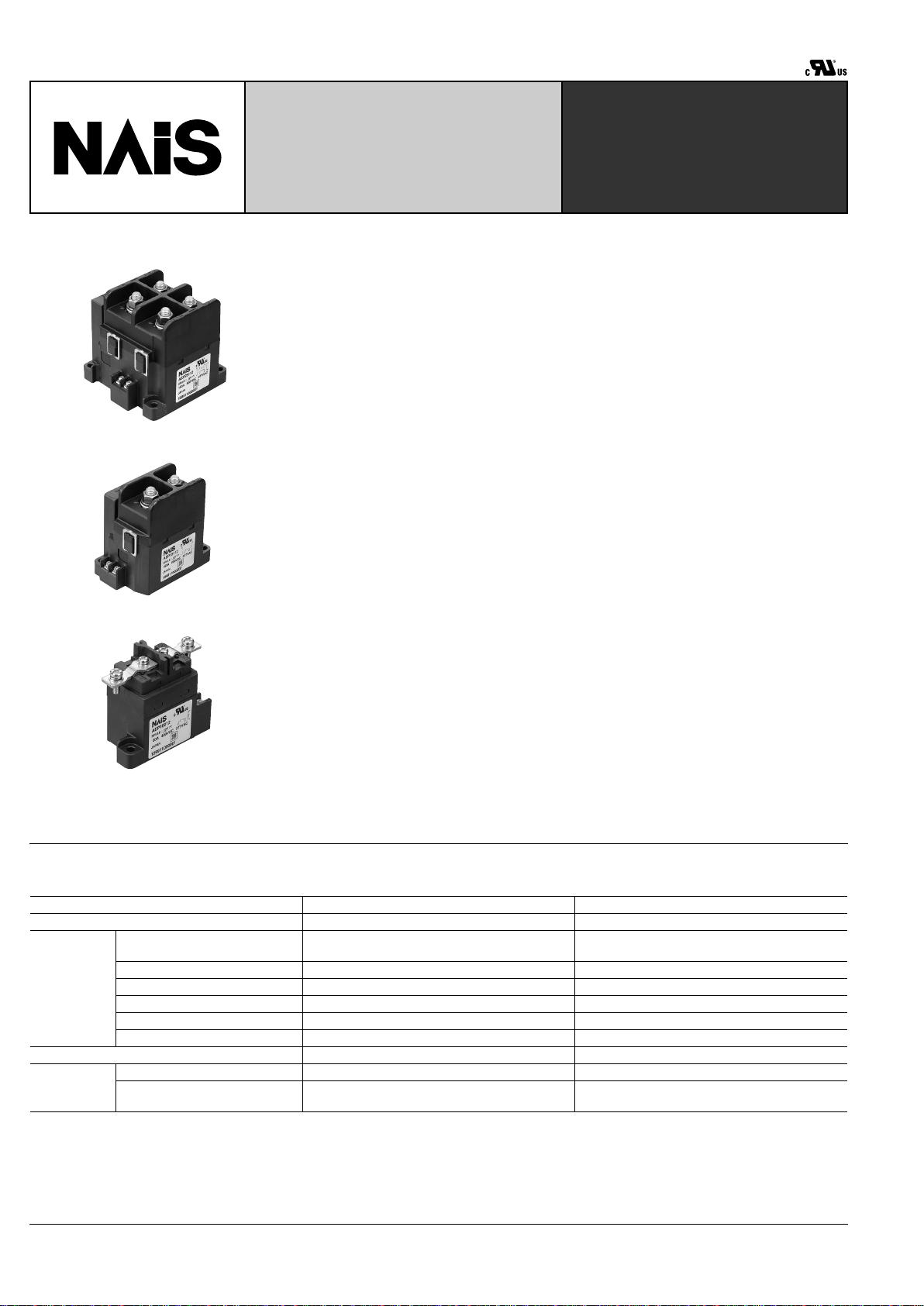
150A 2 Form A
150A 1 Form A
60A
FEATURES
• Control of large voltages and currents
The relays have a sealed construction
that is filled with a hydrogen gas compound, and use a permanent magnet to
establish a magnetic path for the arc. This
allows them to switch high-level DC voltages of up to 400V DC.
• Compact size and light weight
The capsule contact construction is filled
with a gas that has excellent thermal dissipation and insulation characteristics.
Because of this we have been able to reduce the contact gap to one tenth that of
conventional relays, and produce a compact and light design.
• No arc space is required: size including arc space 1/9 (compared to conventional contactors)
The arc is not exposed to the outside,
therefore, no arc space is not required.
• Safety construction
The arc is not exposed, therefore, the
contactor is explosion proof and intrinsically safe.
• Quiet: operation noise 1/4 (compared
to conventional contactors).
Along with the above-mentioned miniaturization, the operation noise has been reduced to 70dB, and, in addition, the
operation noise remains unchanged
when a current of 1000A or more is interrupted.
• High contact reliability
The contact part is hermetically sealed,
hence the contact resistance remains stable regardless of the ambient conditions.
• Mounting direction is not specified
The weight of the movable parts is light,
and also the restoring force is large,
hence the contactor is relatively unaffected by gravity.
• Line-up of indicator types (150A T ype
only)
1 Form A and 1 Form B types with indicators for detecting welding of the main contacts are available.
• 12 and 24V DC coil voltage types are
available.
• Screw terminal blocks for easy wiring.
SPECIFICATIONS
Contact
Notes:
Same specifications as the 12 V type.
#1
Condition: Nominal switching 100cycles, each cut off 2,500A
#2
Conditions: Varistor used for coil surge absorption. Note: if a diode is used the life will be lower.
Type 150A type 60A type
Arrangement 1 Form A, 2 Form A 1 Form A
Rating
Nominal switching capacity
(resistive load)
150A 400V DC
150A 277V AC
60A 400V DC
60A 277V AC
Short term current 300A (10min)(harness wire: 40mm
2
) 120A (15min)(harness wire: 15mm
2
)
Max. cut-off current 2,500A 300V DC (3 cycles)
#1
600A 300V DC (5 cycles)
Overload opening/closing rating 600A 400V DC (Min. 1,000 cycles) 180A 400V DC (Min. 100 cycles)
#2
Reverse cut-off current –200A 200V DC (Min. 500 cycles) –60A 200V DC (Min. 1,000 cycles)
#2
Contact voltage drop (Max.) 0.1V (When current [is 150A per 1] contact set) 0.1V (When current [is 60A per 1] contact set)
Nominal operating power 35W (Inrush, approx 0.1s) 5W ( Stable ) Max. 5W
Expected life
(min.
operations)
Mechanical 10
5
2 ×
10
5
Electrical
3 × 10
3
150A 400V DC
(L/R
&
1ms)
3 × 10
3
60A 400V DC
(L/R
&
1ms
#2
)

EP
389
Characteristics
Remarks:
*
1
Measurement at same location as "Initial breakdown voltage" section.
*
2
Detection current: 10mA.
*
3
Nominal voltage applied to the coil, excluding bounce time.
*
4
Nominal voltage applied to the coil.
*
5
Half-wave pulse of sine wave: 11 ms; detection time: 10 µ s.
*
6
Half-wave pulse of sine wave: 6 ms.
*
7
Detection time: 10 µ s .
*
8
3 directions, each 4 hours.
*
9
Storage: Max.85 ° C 185 ° F.
Initial insulation resistance Min. 100 M Ω (at 500 V DC)*
1
Initial breakdown voltage
Between open contacts AC 2,500 Vrms for 1 min.*
2
Between contact and coil AC 2,500 Vrms for 1 min.*
2
Operate time (at 20 ° C) (at nominal voltage) Max. 50ms*
3
Reset time (without diode) (at 20 ° C) (at nominal voltage) Max. 30ms*
4
Shock resistance
Functional Min. 196 m/s
2
{20 G}*
5
Destructive Min. 490 m/s
2
{50 G}*
6
Vibration resistance
Functional 43 m/s
2
{4.4 G} 10 to 200Hz*
7
Destructive 43 m/s
2
{4.4 G} 10 to 200 Hz*
8
Conditions for operation,
transport and storage
(Not freezing and condensing at low
temperature)
Ambient temperature
–40 ° C to +80 ° C*
9
–40 ° F to +176 ° F
Humidity 5 to 85% R.H.
Unit weight
150 A 1 Form A: 600 g 21.16oz
150 A 2 Form A: 1,100 g 38.80oz
60 A: 340 g 12.00oz
Indicator ratings
Note: Indicator type is only available for the 150 A type.
Arrangement 1 Form A 1 Form B
Material Gold-clad
Rating(resistive load) 0.1 A 30 V DC
Contact resistance Max. 100 m Ω
TYPICAL APPLICATIONS
• UPS (uninterruptible power supplies)
• Solar power generation systems
• Unmanned transport carts
• Battery inspection and testing equipment
• Welding equipment
ORDERING INFORMATION
Product Name
EP
Contact arrangement Contact rating Coil voltage
1: 1 Form A
2: 2 Form A
5: 150A
6: 60A
0: without indicator contact
1: a contact (150A type only)
3: b contact (150A type only)
Indicator contact
arrangement
12: 12V DC
24: 24V DC
Ex. A EP 1 5 0 12
EP
390
TYPES AND COIL DATA (at 20 ° C 68 ° F)
Note: *Same coil data as Indicator type. When using a DC power supply use one that has a leeway of at least 150% current capacity.
Part No.
Coil voltage,
V DC
Pick-up voltage,
V DC (max.)
(at 20 ° C)
Drop-out voltage,
V DC (min.)
(at 20 ° C)
Nominal coil
current, mA ( ± 10%)
(at 20 ° C)
Operating power, W
(12 V DC, at 20 ° C)
Max. allowable
voltage, V DC
AEP25012*
12 V DC 9 V DC 1 V DC
2.8 A
(at peak)*
35W(Inrush,
approx. 0.1S)
5W(Stable)
16 V DCAEP15012*
AEP16012 0.415 A Max. 5W
AEP25024*
24 V DC 18 V DC 2 V DC
1.9 A
(at peak)*
35W(Inrush,
approx. 0.1S)
Max. 5W (1 F orm A)
Max. 6W (2 F orm A)
32 V DC
AEP15024*
2.2 A
(at peak)*
AEP16024 0.208 A Max. 5W
Packing quantity
Types Inner Outer
150A 2 Form A 1pc. 5pcs.
150A 1 Form A 1pc. 10pcs.
60A 1 Form A 1pc. 20pcs.
SPARE PARTS
Installing parts Part No. Packing Quantity
M8 nut with washer for
150A type
AEV801 2pcs.
M5 screw for 60A type AEV802 2pcs.
M4 screw for 30A type AEV803 2pcs.
Bus bar for 60A type AEV804 1pc.
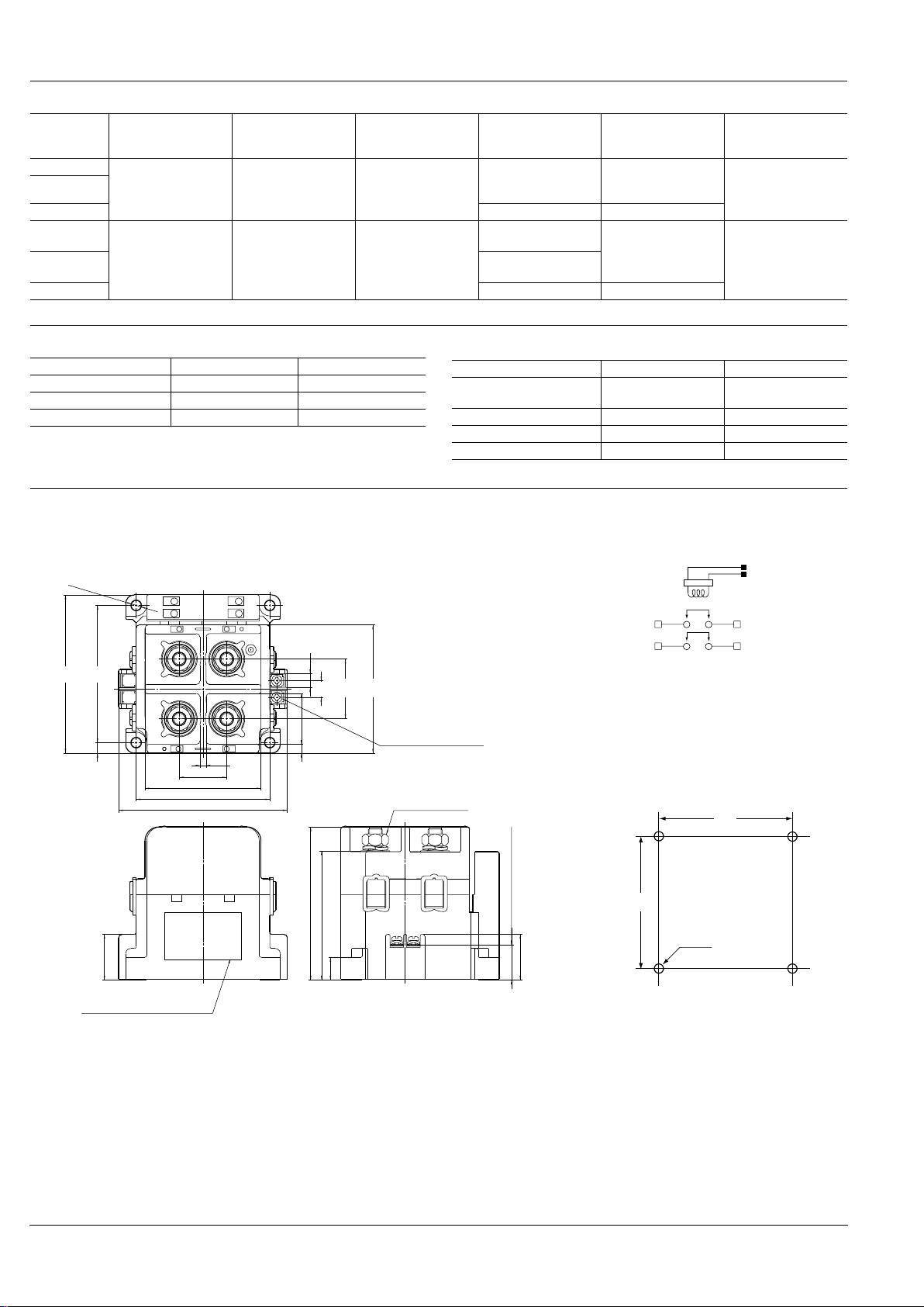
DIMENSIONS
150A 2 Form A
3.5
.138
27.0 1.063
66.0 2.598
96.0 3.780
±0.2
76.0
±.008
2.992
5
.197
29.0
1.142
7.7
.303
Coil input terminal (M3.5)
5 terminal: input (+) side
6 terminal: input (–) side
6
.236
26.0
1.024
Plate (Part No., rating,
schematic and Lot No.)
20.0 .787
(terminal height)
26.0
1.024
13.0
.512
73.5 2.894
(terminal height)
87.1
3.429
M8 nut; AEV801
3
-
+
1
4
2
-
+
3
-
4
+
6
7
8
9
9
X
Y
Z
1
9
2
3
4
5
65
2
-
+
1
87
4- 5.5
φ
±0.1
4- .217
φ
±.004
±0.2
78.0
±.008
3.071
90.0
3.543
9.5
.374
34.0
1.339
73.0
2.874
Schematic (TOP VIEW)
Mounting dimensions
6: Coil (–)
5: Coil (+)
2–
4+
1+
3–
Both input and load sides have polarities (+) and (–).
76
2.992
4- .217
φ
4- 5.5
φ
78
3.071
General tolerance:
less than 10 .394 ± 0.3 ± .012
10 .394 to 50 1.969 ± 0.6 ± .024
more than 50 1.969 ± 1.0 ± .039
mm inch
 Loading...