

Page 1

m
be certain.
Series LX Laser Extensometer
Product Information
LX 500
LX 1500
015-207-801 F
Page 2

Copyright information © 1999–2001, 2006, 2009 MTS Systems Corporation. All rights reserved.
Trademark information MTS is a registered trademark of MTS Systems Corporation within the United
States. These trademarks may be protected in other countries.
Super Glue is a trademark or Super Glue Corporation. All other trademarks or
service marks are property of their respective owners.
Publication information
MANUAL PART NUMBER PUBLICATION DATE
015-207-801 A April 1999
015-207-801 B April 2000
015-207-801 C May 2001
015-207-801 D May 2006
015-207-801 E March 2009
015-207-801 F August 2009
Page 3

Contents
Technical Support 5
Preface 11
Conventions 12
Introduction 15
Specifications 17
Component Identification 19
Controls and Components 20
Safety 23
Labels and Warning Logotypes 25
Additional Safety Cautions 26
Safety Checkout 27
Installation 29
Mechanical Mounting 30
Electrical Connections 33
Modular Jack Pin Identification 33
Operation 35
Target Types and Considerations 36
Target Placement 37
Manual Name Contents
3
Page 4

Monitoring the Reflection Pulses 38
Using the Instrument 39
Setting the Operating Parameters from the Key Pad 39
Description of the Operating Parameters 40
Measuring Elongation 44
Using the Serial Interface 45
Serial I/O Port Cable Connections 46
Communications Parameters 47
Control Commands for Serial Input/Output Port 48
Calibration 52
Entering the Calibration Mode 53
Maintenance 55
Recommended Maintenance Schedule 56
Component Locations 57
Scan Aperture Cleaning Procedure 59
Replacing the Fuse 60
4
Contents
Manual Name
Page 5

Technical Support
How to Get Technical Support
Start with your
manuals
Technical support
methods
MTS web site
www.mts.com
E-mail techsupport@mts.com
Telephone MTS Call Center 800-328-2255
Fax 952-937-4515
Technical support
outside the U.S.
The manuals supplied by MTS provide most of the information you need to use
and maintain your equipment. If your equipment includes MTS software, look
for online help and README files that contain additional product information.
If you cannot find answers to your technical questions from these sources, you
can use the internet, e-mail, telephone, or fax to contact MTS for assistance.
MTS provides a full range of support services after your system is installed. If
you have any questions about a system or product, contact MTS in one of the
following ways.
The MTS web site gives you access to our technical support staff by means of a
Technical Support link:
www.mts.com > Contact MTS > Service & Technical Support
Weekdays 7:00 A.M. to 5:00 P.M., Central Time
Please include “Technical Support” in the subject line.
For technical support outside the United States, contact your local sales and
service office. For a list of worldwide sales and service locations and contact
information, use the Global MTS link at the MTS web site:
www.mts.com > Global MTS > (choose your region in the right-hand
column) > (choose the location closest to you)
LX Laser Extensometer Technical Support
5
Page 6

Before You Contact MTS
MTS can help you more efficiently if you have the following information
available when you contact us for support.
Know your site
number and system
number
Know information from
prior technical
The site number contains your company number and identifies your equipmen t
type (material testing, simulation, and so forth). The number is usually written on
a label on your MTS equipment before the system leaves MTS. If you do not
have or do not know your MTS site number, contact your MTS sales engineer.
Example site number: 571167
When you have more than one MTS system, the system job number identifies
which system you are calling about. You can find your job number in the papers
sent to you when you ordered your system.
Example system number: US1.42460
If you have contacted MTS about this problem before, we can recall your file.
You will need to tell us the:
assistance
• MTS notification number
• Name of the person who helped you
Identify the problem Describe the problem you are experiencing and know the answers to the
following questions:
• How long and how often has the problem been occurring?
• Can you reproduce the problem?
Technical Supp ort
6
• Were any hardware or software changes made to the system before the
problem started?
• What are the model numbers of the suspect equipment?
• What model controller are you using (if applicable)?
• What test configuration are you using?
LX Laser Extensometer
Page 7

Know relevant
computer information
If you are experiencing a computer problem, have the following information
available:
• Manufacturer’s name and model number
• Operating software type and service patch information
• Amount of system memory
• Amount of free space on the hard drive in which the application resides
• Current status of hard-drive fragmentation
• Connection status to a corporate network
Know relevant
For software application problems, have the following information available:
software information
• The software application’s name, version number, build number, and if
available, software patch number. This information is displayed briefly
when you launch the application, and can typically be found in the “About”
selection in the “Help” menu.
• It is also helpful if the names of other non-MTS applications that are
running on your computer, such as anti-virus software, screen savers,
keyboard enhancers, print spoolers, and so forth are known and available.
If You Contact MTS by Phone
Your call will be registered by a Call Center agent if you are calling within the
United States or Canada. Before connecting you with a technical support
specialist, the agent will ask you for your site number, name, company , company
address, and the phone number where you can normally be reached.
If you are calling about an issue that has already been assigned a notification
number, please provide that number. You will be assigned a unique notification
number about any new issue.
LX Laser Extensometer Technica l Suppo rt
7
Page 8

Identify system type To assist the Call Center agent with connecting you to the most qualified
technical support specialist available, identify your system as one of the
following types:
• Electromechanical materials test system
• Hydromechanical materials test system
• Vehicle test system
• Vehicle component test system
• Aero test system
Be prepared to
Prepare yourself for troubleshooting while on the phone:
troubleshoot
• Call from a telephone when you are close to the system so that you can try
implementing suggestions made over the phone.
• Have the original operating and application software media available.
• If you are not familiar with all aspects of the equipment operation, have an
experienced user nearby to assist you.
Write down relevant
Prepare yourself in case we need to call you back:
information
• Remember to ask for the notification number.
• Record the name of the person who helped you.
• Write down any specific instructions to be followed, such as data recording
or performance monitoring.
After you call MTS logs and tracks all calls to ensure that you receive assistance and that action
is taken regarding your problem or request. If you have questions about the status
of your problem or have additional information to report, please contact MTS
again and provide your original notification number.
Problem Submittal Form in MTS Manuals
Technical Supp ort
8
Use the Problem Submittal Form to communicate problems you are experiencing
with your MTS software, hardware, manuals, or service which have not been
resolved to your satisfaction through the technical support process. This form
includes check boxes that allow you to indicate the urgency of your problem and
your expectation of an acceptable response time. We guarantee a timely
response—your feedback is important to us.
LX Laser Extensometer
Page 9

The Problem Submittal Form can be accessed:
• In the back of many MTS manuals (postage paid form to be mailed to MTS)
• www.mts.com > Contact Us > Problem Submittal Form (electronic form to
be e-mailed to MTS)
LX Laser Extensometer Technica l Suppo rt
9
Page 10

Technical Supp ort
10
LX Laser Extensometer
Page 11

Preface
Before You Begin
Safety first! Before you attempt to use your MTS product or system, read and understand the
Safety manual and any other safety information provided with your system.
Improper installation, operation, or maintenance of MTS equipment in your test
facility can result in hazardous conditions that can cause severe personal injury or
death and damage to your equipment and specimen. Again, read and understand
the safety information provided with your system before you continue. It is very
important that you remain aware of hazards that apply to your system.
Other MTS manuals In addition to this manual, you may receive additional MTS manuals in paper or
electronic form.
If you have purchased a test system, it may include an MTS System
Documentation CD. This CD contains an electronic copy of the MTS manuals
that pertain to your test system, including hydraulic and mechanical component
manuals, assembly drawings and parts lists, and op eration and preventive
maintenance manuals. Controller and application software manuals are typically
included on the software CD distribution disc(s).
LX Laser Extensometer Preface
11
Page 12

Conventions
DANGER
WARNING
CAUTION
Conventions
Documentation Conventions
The following paragraphs describe some of the conventions that are used in your
MTS manuals.
Hazard conventions As necessary, hazard notices may be embedded in this manual. These notices
contain safety information that is specific to the task to be performed. Hazard
notices immediately precede the step or procedure that may lead to an associated
hazard. Read all hazard notices carefully and follow the directions that are given.
Three different levels of hazard notices may appear in your manuals. Following
are examples of all three levels.
Note For general safety information, see the safety information provided with
your system.
Danger notices indicate the presence of a hazard with a high level of risk which,
if ignored, will result in death, severe personal injury, or substantial property
damage.
12
Warning notices indicate the presence of a hazard with a medium level of risk
which, if ignored, can result in death, severe personal injury, or substantial
property damage.
Caution notices indicate the presence of a hazard with a low level of risk which,
if ignored, could cause moderate or minor personal injury, equipment damage, or
endanger test integrity.
Notes Notes provide additional information about operating your system or highlight
easily overlooked items. For example:
Note Resources that are put back on the hardware lists show up at the end of
the list.
Special terms The first occurrence of special terms is shown in italics.
Preface
LX Laser Extensometer
Page 13

Conventions
Illustrations Illustrations appear in this manual to clarify text. It is important for you to be
aware that these illustrations are examples only and do not necessarily represent
your actual system configuration, test application, or software.
Electronic manual
conventions
This manual is available as an electronic document in the Portable Document
File (PDF) format. It can be viewed on any computer that has Adobe Acrobat
Reader installed.
Hypertext links The electronic document has many hypertext links displayed in a blue font. All
blue words in the body text, along with all contents entries and index page
numbers, are hypertext links. When you click a hypertext link, the application
jumps to the corresponding topic.
LX Laser Extensometer Preface
13
Page 14

Conventions
14
Preface
LX Laser Extensometer
Page 15
Introduction
The MTS Series LX Laser Extensometers are precision, wide range instruments
specifically designed for accurate, non-contact, measurement of strain on various
materials under tensile or creep conditions. The instrument is completely self
contained. It is housed in a single, compact enclosure and utilizes the latest stateof-the-art laser diode technology for high performance, low maintenance
operation. The LX 500 is a high elongation version for measuring the strain of
elastomeric materials. It has a range of 5 to 132 mm (0.2 to 5.2 in). The LX 1500
has a range of approximately 380 mm (approximately 15 in).
The laser extensometer includes a LCD display, a 4-button keypad, a 0 to 10 V
(5 V optional) analog output, and a serial input/output port, all of which are
accessible from the control panel. In addition, the unit can be operated locally
from the control panel using the built-in keypad, or remotely via the Serial I/O
Port.
MTS Series LX Laser Extensometer
LX Laser Extensometer Introduction
15
Page 16

The laser extensometer uses a unique scanning laser beam technique to measure
elongation entirely from one side of the specimen. Two tiny retro-reflective
targets are attached to the specimen at the desired gauge length and the beam is
scanned along the specimen in the direction of elongation. Reflections from these
targets are then processed by the laser extensometer to provide measurement of
elongation (strain). This approach eliminates the need for a separate Scan
Receiver Unit mounted on the opposite side of the specimen.
16
Introduction
LX Laser Extensometer
Page 17
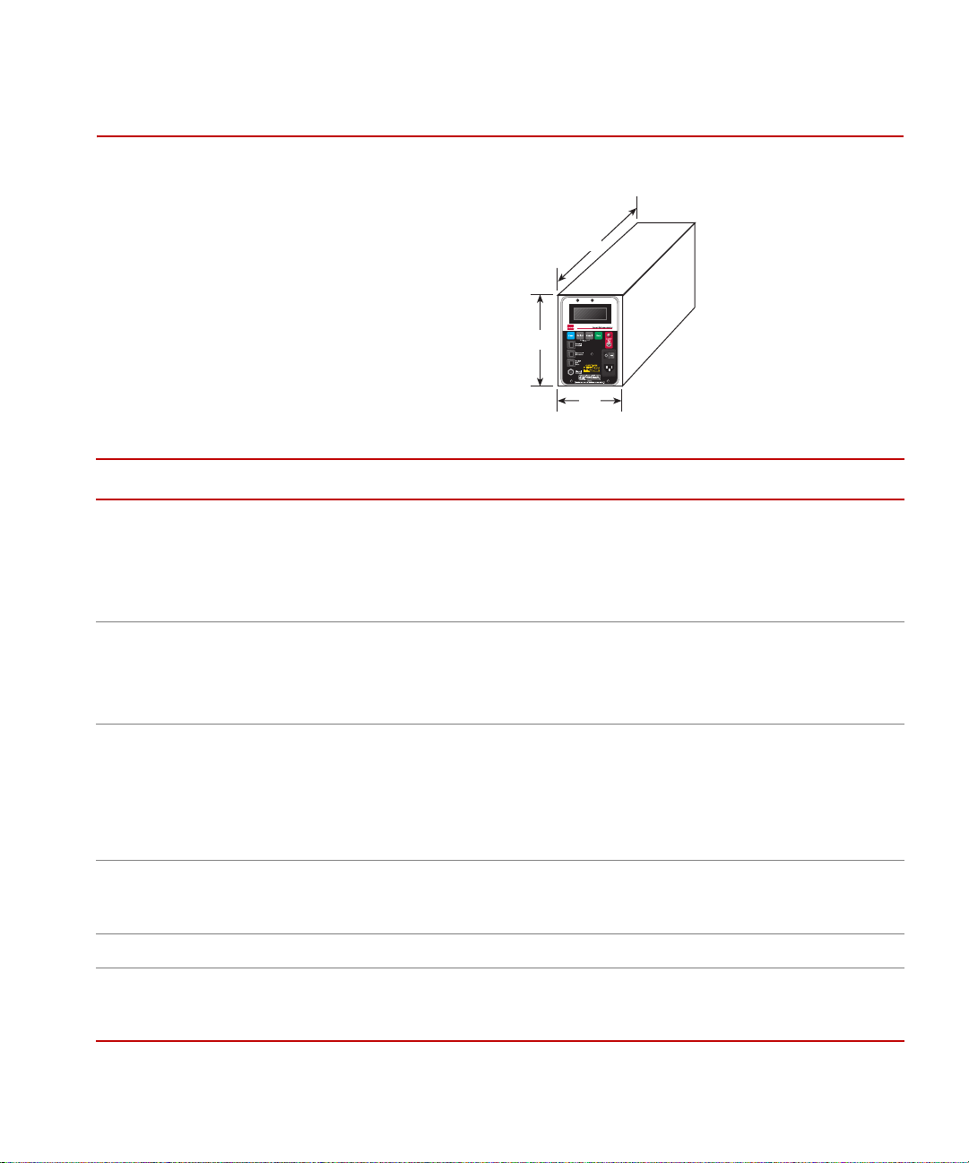
Specifications
W
H
L
Specifications
PARAMETER
Dimensions
(Length [L] x Width [W] x Height [H])
LX 500
LX 1500
Weight
LX 500
LX 1500
Power Input
Voltage
Current
Frequency
Operating Conditions 18 ºC to 28 ºC (64 ºF to 82 ºF)
Mounting Provisions 4 holes (1/4 - 20 thread) located in base
Laser Source 670 nm Diode Laser
TYPICAL SPECIFICATION
381 x 114 x 180 mm (15 x 4.5 x 7.1 in)
686 x 196 x 442 mm (27 x 7.7 x 17.4 in)
5.9 kg (13 lb)
21.8 kg (48 lb)
115 V AC (standard), or 230 V AC (optional), ± 10%
120 mA @ 115 V AC, 60 mA @ 230 V AC
50/60 Hz
25% to 75% relative humidity, noncondensing
0 to 2745 m (0 to 9000 ft) altitude
<1 mW maximum scanned output
CDRH compliant Class II Laser Instrument
*
LX Laser Extensometer Introduction
17
Page 18

Specifications
PARAMETER
TYPICAL SPECIFICATION
*
Scan Line Orientation Vertical
Scan Rate 100 scans/second
Unit System Selectable, millimeter or inch
Target Distance
LX 500
LX 1500
Measurement Range
LX 500
LX 1500
†
Selectable: 304 mm (12 in), 381 mm (15 in)
Selectable: 381 mm (15 in), 457 mm (18 in)
5 to 127 mm (0.2 to 5.0 in)
8 to 381 mm (0.3 to 15 in)
Resolution
LX 500
LX 1500
Nonlinearity (maximum)
LX 500
LX 1500
Repeatability
‡
LX 500
LX 1500
‡
0.001 mm (0.0001 in)
0.01 mm (0.001 in)
±0.025 mm (±0.0001 in)
±0.15 mm (±0.006 in)
±0.003 mm (±0.0001 in)
±0.03 mm (±0.001 in)
Zero Suppression Reading can be zeroed anywhere within the full scale range of the
instrument
Multiple Scan Averaging A moving window average is applied over a programmable number
of scans to digitally filter the output readings
Display 2-line, 16 characters/line LCD type display with LED backlighting
Analog Output Range ±10 V full scale (±5 V full scale optional)
Serial I/0 Port Standard 3-wire type, RS-232
Selectable baud (9600, 4800, 2400, 1200)
Options Consult MTS
* Specifications apply at 25
° C (77° F), 50% relative humidity.
† Contact factory for other ranges.
‡ Over optimum displacement range at calibrated target distance.
18
Introduction
LX Laser Extensometer
Page 19
Component Identification
CAUTION
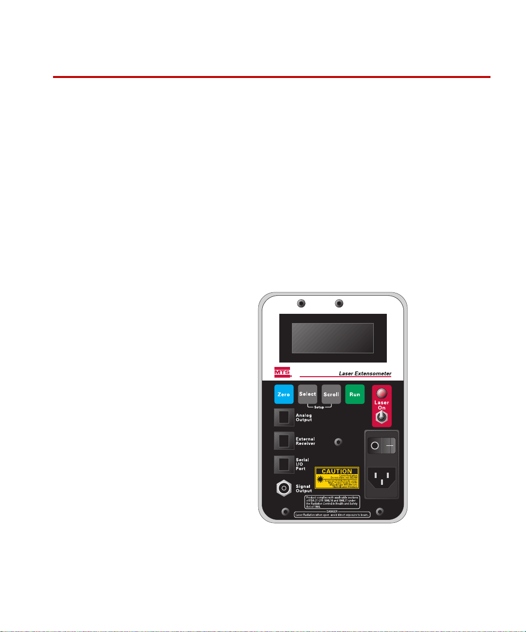
An illustration of the controls necessary for operation is shown below. The Scan
Aperture is located on the opposite side of the instrument.
The scanning laser beam is emitted from the scan aperture.
Avoid exposure.
Component Identification
LX Laser Extensometer Introduction
19
Page 20

Component Identification
Controls and Components
Laser disable switch This switch shuts down the scanning laser beam.
Laser emission indicator This is a red LED lamp that illuminates when the scanning laser beam is present.
Power entry module The fuse holder, the power switch, and the ac line connector are contained in this
module.
Certification label This label certifies compliance with CDRH regulations.
Rear panel warning label This label warns of the presence Laser Radiation inside the instrument.
Warning logotype This label specifies the wavelength and maximum power output of the laser
radiation emitted from the instrument.
LCD display Displays specimen elongation in either inches or millimeters when the instrument
is in the Run mode, and displays the value of various operating parameters when
the instrument is in the Setup mode.
Zero button Pressing the Zero button offsets the current value of specimen elongation to zero
and displays Offset on the LCD display. Subsequent elongation measurements
then become relative to this new zero point. Pressing the Zero button again
removes the offset.
Select button While in Run mode, pressing this button simultaneously with the Scroll button
forces the laser extensometer into the Setup mode. The Select button is then used
to select and accept major items from the Setup menu.
Scroll button While in Run mode, pressing this button simultaneously with the Select button,
forces the laser extensometer into the Setup mode. The Scroll button is then used
to change the value of the selected item in the Setup menu. The Select button
must then be pressed to accept the new value of the selected item.
Run button While in Setup mode, pressing this button returns the laser extensometer to the
Run mode.
Signal Output connector A BNC connector is provided for monitoring the reflections coming back from
the specimen using an oscilloscope. This is especially useful for initial setup or
troubleshooting.
Serial I/O Port connector A modular connector is provided to allow serial input/output connection to a host
computer.
20
Introduction
LX Laser Extensometer
Page 21

Component Identification
External Receiver
connector
Analog Output
connector
A modular connector is provided for this optional accessory.
A modular connector is provided here also. It allows connections to the Analog
Output (a ±10 V DC or
and connections for providing a 5 V level to actuate the optional Remote Laser
Disable function.
±5 V DC signal proportional to specimen elongation),
LX Laser Extensometer Introduction
21
Page 22

Component Identification
22
Introduction
LX Laser Extensometer
Page 23

Safety
CAUTION
Important The Series LX Laser Extensometers are intended for materials
testing laboratories.
The Series LX Laser Extensometers are Class II laser products and, in normal
usage, are not considered hazardous due to the low power of the scanned laser
beam. However, staring into the beam could cause damage to your eyes and
it is up to you to follow all safety precautions and safety labels.
The National Center for Devices and Radiological Health (CDRH) of the U.S.
Food and Drug Administration has established regulations for laser
manufacturers (FDA 21 CFR 1040.10 and 1040.11). The laser extensometer
complies with applicable sections of these regulations and is classified as a Class
II laser product.
A warning logotype, along with other labels identify the unit as a Class II laser
product. Both the warning logotype and the certification label are located on the
control panel, while the manufacturer's identification label is located on the
housing at the rear of the instrument.
In normal usage the laser extensometer is not considered hazardous due to the
low power of the scanned laser beam. However:
LX Laser Extensometer Safety
Staring into the beam could damage the operator’s eyes.
Use caution when measuring reflective parts.
It is up to the operator to follow all safety precautions and safety labels.
The laser extensometer has the following built-in safety features which should be
checked periodically for proper operation.
• A laser emission indicator that illuminates when power is applied to the
laser.
• A laser disable switch that shuts down the laser.
• A laser shutdown circuit that monitors the scan speed and automatically
disables the laser when the scan speed drops below the limit.
23
Page 24

Check operation of these safety features by performing the procedure in the
CAUTION
CAUTION
Safety Checkout section.
Laser radiation present inside. Do not remove case.
Customer servicing of the internal components of the laser extensometer is not
recommended. Return unit to factory for service.
Use of controls or adjustments or performance of procedures other than
those specified herein can result in hazardous radiation exposure.
Always follow the instructions contained in the documentation.
24
Safety
LX Laser Extensometer
Page 25

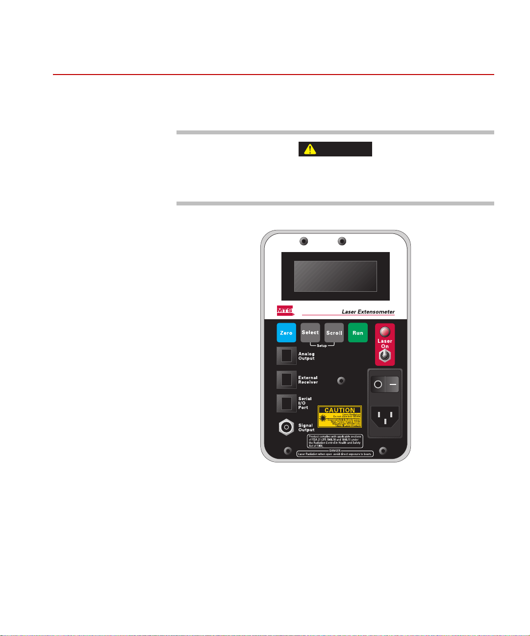
Labels and Warning Logotypes
Manufacture Date
Rev.
Laser Extensometer
Model No.
Serial No.
Assembly No.
MTS Systems Corporation
14000 Technology Drive
Eden Prairie, MN U.S.A. 55344
Supply Rating
No user serviceable parts inside
V Hz
AVOID EXPOSURE
- Laser radiation
is emitted from this aperature
The following figure shows the labels and warning logotypes that are found on
the laser extensometer.
Labels and Warning Logotypes
LX Laser Extensometer Safety
25
Page 26

Labels and Warning Logotypes
CAUTION
Additional Safety Cautions
Besides the safety cautions listed on the previous page, you should read,
understand, and follow these additional safety cautions:
Before attempting to operate the instrument, read an d underst a nd the enti re
manual. Follow all safety precautions and warning labels.
This instrument is a technical product for use only by skilled personnel in an
indoor laboratory environment wit h a normal, controlled, 25ºC, 55% relative
humidity. This instrument is not for outdoor use. Do not expose to moisture.
Properly handle and install this instrument on a stable, solid mounting surface
suitable for safely handling its weight and size. Failure to do so can present a
safety hazard and result in damage to the instrument. The instrument is not for
hand held use.
There are 170 user serviceable components inside the instrument. Do not attempt
to open or remove the case. Dangerous voltages and laser radiation are present
inside. Return the instrument to the factory for service.
Do not make any modifications to the instrument. Doing so will void the warranty
and can also result in a hazardous condition.
To reduce the risk of electrical shock, the instrument must be connected to the AC
Main power line using the proper, grounded 3-prong line cord.
Before performing any maintenance, turn the power switch to OFF position and
disconnect unit from the AC Main power line.
Replace fuses with only the specified type and rating. Using incorrect fuses can
present a safety hazard and damage the instrument.
26
Safety
LX Laser Extensometer
Page 27

Safety Checkout
Labels and Warning Logotypes
1. Check the laser emission indicator.
With the laser extensometer ON and the LASER DISABLE SWITCH in the
LASER ON position, verify that the LA SER EMISSION INDICATOR is
illuminated only when the scanning Laser Beam is present.
2. Check the laser disable switch.
With the laser extensometer ON and the scanning Laser Beam present,
verify that the LASER DISABLE SWITCH shuts down the scanning Laser
Beam.
3. Check the laser shutdown circuit.
Verify this feature is functional by observing th e delayed appearance of the
scanning laser beam when the laser is enabled.
A. Start with the laser extensometer on and the scanning laser beam
present. Set the laser disable switch to the off position to shut down the
scanning laser beam.
B. Allow approximately one minute to elapse until the scan motor stops
rotating.
C. Return the laser disable switch to the on position and note the time
delay before the scanning laser beam appears.
D. The beam should appear a few seconds after
to the on position. If no time delay is observed, the laser shutdown
circuit is not operating properly. Contact MTS for service.
4. Check laser power level.
This check verifies the Laser Emission Level is within the acceptable range
for a Class II laser product. You will need an optical power meter calibrated
for a wavelength of 670 nm with a minimum full scale range of 1.0 mW.
A. Turn the laser extensometer on and allow a 30 minute warm up time.
B. Turn on the optical power meter. Set controls per the manufacturer's
instructions.
C. Position the measuring head of the optical power meter in the scanning
laser beam. Measure and record the power reading. The output power
reading must be less than 1.0 mW; if not, contact MTS for service.
setting the disable switch
LX Laser Extensometer Safety
27
Page 28

Labels and Warning Logotypes
CAUTION
Laser radiation present inside. Observe the following cautions:
Customer servicing of the internal components is not recommended; return
unit to factory for service. (Opening the case invalidates all warranties.)
Before performing maintenance, turn power switch to the off position and
disconnect the unit from the AC power line.
If a malfunction occurs, immediately shut down the malfunctioning unit and
contact MTS for repairs.
Do not open or remove the case. Laser radiation is present inside the instrument.
28
Safety
LX Laser Extensometer
Page 29

Installation
Contents Mechanical Mounting 30
Electrical Connections 33
LX Laser Extensometer Installation
29
Page 30

Mechanical Mounting
Mechanical Mounting
Proper installation of the unit is essential for best performance. It is important
that the instrument be solidly mounted on a flat surface and that the scanning
laser beam be properly positioned on the target; see “Tripod Mounting Adapter”
on page 31. It is recommended that the laser extensometer be mounted on four
machined spacers 12.7 mm (0.500 in) diameter by 12.7 mm (0.500 in) long, with
1/4-20 bolts using the four threaded mounting holes locate d in the base of the
unit. The purpose of these spacers is to provide 4 solid contact areas between the
bottom of the Laser Extensometer and the mounting surface. The spacers and the
mounting surface must be fabricated using good machining practice such that,
with the mounting bolts loose, the laser extensometer rests flat contacting all 4
spacers simultaneously.
Choose the mounting location of the laser extensometer such that the specimen to
be measured ends up at the appropriate target distance from the instrument,
where target distance refers to the distance between the front panel of the laser
extensometer and the targeted surface of the specimen. Try to locate the LX500
so that a 304 mm (12 in) target distance results; for the LX1500, try for a target
distance of 381 mm (15 in). If this is not a practical distance for the intended
application, then choose another distance: for the LX500, 381 mm (15 in); for the
LX1500, 457 mm (18 in).
30
Installation
Important Calibration is a function of target distance, and the instrument must
be calibrated at the target distance (or distances) it will be operated
at. Contact factory for details.
Orient the laser extensometer so that the scan line is aligned parallel with the
specimen's axis of elongation; see “Scan Line Orientation on Specimen” on page
32. It is important to position the laser extensometer properly with respect to the
specimen in order to avoid possible spurious reflections. These reflections
usually result from scanning orthogonally across a bright, shiny surface. This
happens in situations where the plane of the scan line is orthogonal to the plane
containing the surface of a shiny specimen. The presence of spurious reflections
is suspected when unstable or invalid readings occur. These reflections can
typically be eliminated by rotating the offending surface of the specimen a small
amount (≈5° to 10°) about the axis of the scan line; see “Scan Line Orientation on
Specimen” on page 32.
LX Laser Extensometer
Page 31

Mechanical Mounting
19.56
20.00
14.00
11.69
10.00
8.31
6.00
.00
.44
.00
.44
.81
2.31
3.81
4.19
4.62
.50
.25
.00
.62
2.56
1.03
4.00
10.00
9.125
8.00
.281 DIA THRU (4)
.428
1. 00
4.62
3.75
3.385
3.00
.435
.618
.810
3.308
3.385
#8-32 UNC-2B THRU
.25 X .25 Chamfer (4)
.38/35
.281 DIA THRU
3/8-16 UNC-2B THRU
.25 X .25
Chamfer (4)
#8-32 UNC-2B THRU (4)
.281 DIA THRU
.00
LX 500
LX 1500
The installation should then be checked with the specimen installed by
monitoring the reflection pulses at the Signal Output jack using an oscilloscope
per the procedure described in the Operation section of this manual under
Monitoring the Reflection Pulses.
Tripod Mou nting Adapter
LX Laser Extensometer Installation
31
Page 32

Mechanical Mounting
Side View
90º
Specimen
Scan Line
Viewed from the Side
Front View
Target #2
edge
Target #1
edge
Specimen
Scan Line
80º
Laser Extensometer Front Panel
Scan Line
Target Distance
Eliminating Spurious
Reflection Problem
Rotate specimen as shown to direct
spurious reflections away from the
scan line.
Spurious Reflection
Specimen
Top View
90º
Specimen
Top View
Laser Extensometer Front Panel
Scan Line
Target Distance
Spurious Reflection
Potential Spurious
Reflection Problem
Eliminating Spurious
Reflection Problem
Specimen
Target Distance
Rotate laser extensometer as shown
to direct spurious reflections away
from the scan line.
Top View
80º
Laser Extensometer Front Panel
Scan Line
Spurious Reflection
Scan Line Orientation on Specimen
32
Installation
LX Laser Extensometer
Page 33

Electrical Connections
The Series LX Laser Extensometers are connected to line voltage power using
the grounded cord provided.
The Analog Output signal, the Remote Laser Disable signal, and the Serial I/
O Port connections are made via the modular jacks located on the control panel
of the instrument. Note these jacks have 6 pins but only 4 pins are used. A
standard RJII 4-pin telephone type Modular Plug will mate with them and
automatically make contact only with the 4 active pins (pins 2, 3, 4, and 5).
For EMC compliance, when installing the LX 500 and LX 1500 Laser
Extensometers all cable connections must use shielded cables (this includes the
RJ11 modular plug connections and the AC Line Cord connections to the Laser
Extensometer). The shield must be tied to earth ground. The case of the Laser
Extensometer is also earth-grounded.
Note No external cables are to be connected to the BNC connector on the
Laser Extensometer because this is only a “test” connector and is not
normally used.
Electrical Connections
Modular Jack Pin Identification
Face the controls side of the laser extensometer. The notch in the jack is on the
left and the pins are numbered vertically, in sequential fashion, from 1 to 6 with
pin number 1 at the top.
Both the analog output signal and the remote laser disable signal connections are
located on the Analog Output jack. The Analog Output modular jack uses only
4 pins:
• pin 1 no connection
• pin 2 analog output (-) (gnd)
• pin 3 remote laser disable (-)
• pin 4 analog output (+)
• pin 5 remote laser disable (+)
• pin 6 no connection
LX Laser Extensometer Installation
33
Page 34

Electrical Connections
The laser extensometer must be configured in order for the remote laser disable
function to operate; contact MTS for configuration information. A 5 V level must
be applied across pins 5 and 3 to turn the laser on. Removing the applied 5 V
level turns the laser off.
The serial input/output connects to the modular jack labeled Serial I/O Port
located on the controls side of the instrument. The Serial I/O Port modular jack
uses only 4 pins:
• pin 1 not used (reserved)
• pin 2 gnd
• pin 3 transmit data
• pin 4 receive data
• pin 5 gnd
• pin 6 no connection
An accessory cable assembly (7.6 m [25 ft.], MTS part number
056-128-904) is available with a standard 9-pin D female connector for direct
connection to the serial port of an IBM compatible PC; contact MTS for
additional information.
34
Installation
LX Laser Extensometer
Page 35

Operation
CAUTION
Laser radiation present.
Before attempting to operate instrument:
• Read and understand the entire manual
• Follow all safety precautions and warning labels
• Do not stare directly into beam
• Use caution when measuring reflective parts
• Do not stare into reflected beam
The Series LX Laser Extensometers must be installed as described in the
Installation section of this Manual. The unit works by sensing reflections from
retro-reflective tape strips applied to the specimen. T wo tiny strips are attached to
the specimen, one at each end of the gauge length. These function as targets and
the laser extensometer, via the scanning laser beam, determines the distance
between selected edges of these targets.
LX Laser Extensometer Operation
35
Page 36

Target Types and Considerations
Target Types and Considerations
Basically , targeting the specimen is accomplished by either attaching tape strips
directly to the specimen or by applying the tape strips to tiny spring clips and
attaching these spring clips to the specimen. The spring clip type target is
reusable. Care must be taken to ensure no damage occurs to the retro-reflective
surfaces during use.
Note Some medical researchers have attached reflective tapes with surgical
sutures. Others have used a general purpose adhesive (such as Super
Glue).
The retro-reflectivity of both targets must be approximately the same. This will
be the case as long as the surface of both targets is kept clean, dry, and
undamaged. However, if the surface is damaged or if there is a buildup of foreign
matter, the targets must be replaced. It is advisable to replac e both tar gets as a set
(that is, do not replace individually).
In general, the target width should be kept as small as possible. However, if the
targets are too narrow, problems can arise. These potential problems can be
avoided by observing the minimum recommended target width of 1.02 mm
(0.040 in).
36
Operation
LX Laser Extensometer
Page 37

Target Placement
Depending on the measurement mode selected, the laser extensometer measures
the distance between the front edges of targets T
the front edges of targets T
each scan.
The target edges are labeled as follows:
• T
• T
• T
• T
and T2, T2 and T3, T3 and T4 successively during
1
is the front edge of target 1
1
is the front edge of target 2
2
is the front edge of target 3
3
is the front edge of target 4
4
Target Placement
and T2, or the distance between
1
In the T
- Tl measurement mode, the targets T1 and T2 are positioned such that
2
the front edges are coincident with the gauge length. In the multisegment
measurement mode, the targets T
the front edges of T
and T4 aligned with the gauge length.
1
, T2, T3, and T4 are arranged sequentially with
1
LX Laser Extensometer Operation
37
Page 38

Monitoring the Reflection Pulses
Reflection from
Target #2
Reflection from
Target #1
Normal reflection pulses viewed
on the oscilloscope at the Signal
Output jack on the control panel.
Spurious reflection pulse
viewed on the oscilloscope
at the Signal Output jack on
the control panel.
Direction of
Elongation
Front View
Target #2
edge
Target #1
edge
Specimen
Scan Line
Monitoring the Reflection Pulses
Connecting an oscilloscope to the Signal Output BNC connector allows the
reflection signal to be monitored. This is very handy during setup or
troubleshooting, especially when checking for spurious reflections from the
specimen.
Set the oscilloscope controls as follows:
• Time Base = 1 msec per division
• Amplitude = 2 V per division
• Trigger = Positive Slope
Adjust the oscilloscope trigger level until there are two pulses of 5 V amplitude
with sharp edges and flat tops; see “Reflection Pulses” below. Any additional
pulses indicate the presence of spurious reflections which must be identified and
eliminated for proper operation of the instrument.
Spurious reflections usually result from scanning orthogonally to shiny, flat
surfaces. These reflections can typically be eliminated by rotating the offending
surface a small amount (≈5° to 10°) about the axis of the scan line; see “Scan
Line Orientation on Specimen” on page 32.
38
Operation
Reflection Pulses
LX Laser Extensometer
Page 39

Using the Instrument
The laser extensometer can be controlled from the keypad on the control panel of
the instrument or from the Serial I/O Port via a remote computer. Serial
operation is covered in the Using the Serial Interface section of this manual.
Setting the Operating Parameters from the Key Pad
There are two modes of operation, the Setup mode and the Run mode. When the
laser extensometer is powered up it automatically enters the Run mode. In order
to change operating parameters, the unit must be placed in the Setup mode.
1. Attach the line cord and apply power to the unit and turn power switch to
“ON”. The LCD display will illuminate.
2. From the Run mode, press the Select button and the Scroll button
simultaneously. This causes the laser extensometer to enter the Setup mode
with the first menu Item appearing on the LCD display.
3. In the Setup mode, the Select button is used to select and accept major
items from the Setup menu while the Scroll button is used to change the
value of the item selected in the Setup menu.
Using the Instrument
4. After the selected menu item has been scrolled to a different value, the
Select button must then be pressed to accept this new value.
5. Press the Run button to return to the Run mode. Please Wait can appear
temporarily on the LCD display depending on the parameters changed in the
Setup mode.
LX Laser Extensometer Operation
39
Page 40

Using the Instrument
Description of the Operating Parameters
In Setup Mode, the selected parameter appears on the top line of the LCD display
along with its corresponding value appearing on the bottom line. A detailed
description of each parameter is given below.
1. Select Units - sets the units to Inches or Millimeters.
2. Analog Output - sets the full-scale range of the Analog Output. Because
the Analog Output has 16-bit resolution and is updated continuously at a
rate of 100 times per second, it can be used as a strain feedback signal for
closed loop applications. The full scale range of the Analog Output
depends on the system of units set in the Select Units parameter. The fullscale range choices for the LX 500 are:
0.1 in = 10 V (5 V) (for inch units)
2.0 mm = 10 V (5 V) (for mm units)
0.2 in = 10 V (5 V) (for inch units)
5.0 mm = 10 V (5 V) (for mm units)
0.5 in = 10 V (5 V) (for inch units)
10 mm = 10 V (5 V) (for mm units)
40
Operation
1.0 in = 10 V (5 V) (for inch units)
20 mm = 10 V (5 V) (for mm units)
2.0 in = 10 V (5 V) (for inch units)
50 mm = 10 V (5 V) (for mm units)
5.0 in = 10 V (5 V) (for inch units)
100 mm = 10 V (5 V) (for mm units)
Note The full-scale range choices for the LX 1500 are:
0.1 in = 10 V (for inch units)
2.0 mm = 10 V (for mm units)
through
20 in = 10 V (for inch units)
500 mm = 10 V (for mm units)
Six intermediate ranges are also included.
3. Target Distance - Sets the Target Distance. This is the distance from the
front panel of the Laser Extensometer to the targeted surface of the
specimen. This parameter depends on the system of units set in the SELECT
UNITS parameter. The choices appear on the LCD display.
LX Laser Extensometer
Page 41

Using the Instrument
4. # Scans Averaged - Sets the number of scans over which the elongation
measurements are averaged. The laser extensometer uses a moving window
method of averaging which allows smooth performance. Increasing the
number of scans averaged improves resolution and slows response time
(that is, bandwidth) of the elongation measurement. The choices are as
follows:
2 Scans Averaged
4 Scans Averaged
8 Scans Averaged
16 Scans Averaged
32 Scans Averaged
64 Scans Averaged
128 Scans A veraged
256 Scans A veraged
512 Scans A veraged
LX Laser Extensometer Operation
41
Page 42

Using the Instrument
5. Measurement Type - Sets the type of Measurement performed. The laser
extensometer measures the distance between the front edge of each target.
The target edges are labeled as follows:
= front edge of target 1
T
1
= front edge of target 2
T
2
= front edge of target 3
T
3
= front edge of target 4
T
4
The choices for measurement type are:
- TI distance between front edges of first two targets (T1 and T2)
T
2
MULTISEGMENT = simultaneous measurement of the 3 intervening
segments between front edges of targets T
- T1 = distance between front edges of first and second targets (T1 and
T
2
T
).
2
- T2 = distance between front edges of second and third targets (T2 and
T
3
T
).
3
--T2--T3--T4 respectively.
l
- T3= distance between front edges of third and fourth targets (T3 and T4).
T
4
For the T
- T1 measurement type setting, only two targets are required.
2
These targets are positioned such that the front edges are coincident with the
gauge length.
For the Multisegment measurement type setting all four targets are
required. They are arranged sequentially within the gage length and define
the three segments over which the measurements are taken. Segment 1 is
intervening distance between front edges of first two targets (T
-T1).
2
Similarly, Segment 2 is the distance between front edges of the second and
third targets (T
the third and fourth targets (T
-T2) and Segment 3 is the distance between front edges of
3
- T3). All three segments are measured
4
simultaneously. However, they are only available simultaneously over the
serial input/output port. Only one segment at a time can be monitored at the
Analog Output and on the LCD display. The segment being monitored is
indicated by a 1, 2, or 3 in the lower left corner of the LCD display. A 1
indicates the first segment (T
T
), and a 3 indicates the third segment (T4 -T3). Use the Scroll button to
2
-T1.), a 2 indicates the second segment (T3 -
2
select the segment you want to monitor; a segment displayed on the LCD
display is also applied to the Analog Output. The Zero button zeroes all
three segments simultaneously.
42
Operation
LX Laser Extensometer
Page 43

Using the Instrument
6. External Receiver - Sets up the laser extensometer to accept input from the
optional External Scan Receiver Unit. This optional accessory is useful for
applications where it is necessary to shoot through the specimen. It is
usually mounted behind the specimen in order to measure portions of the
scanning laser beam shadowed by the specimen. The External Scan
Receiver Unit must be connected before its use by the laser extensometer
can be enabled.
The choices for External Receiver are:
– enabled - External Receiver connected and enabled for use by laser
extensometer.
– disconnected - External Receiver not connected and can not be
enabled for use by the laser extensometer.
– disabled - External Receiver is connected but its use by the laser
extensometer is disabled (that is, not used).
7. BAUD - Sets the BAUD for the Serial I/O Port. The choices are: 9600,
4800, 2400, and 1200.
LX Laser Extensometer Operation
43
Page 44

Using the Instrument
CAUTION
Measuring Elongation
Do not stare directly into the beam.
Use caution when measuring reflective parts. Do not stare into reflected beam.
1. With the line cord attached and power applied to the unit, turn power switch
to O position. The LCD display will illuminate.
2. Set the laser disable switch to the Laser On position.
3. Set the operating parameters to the desired values using the procedure
previously described. Make certain that the target distance has been set to
the proper value.
4. Attach the retro-reflective targets to the specimen using the desired method
described previously under Target Types and Considerations.
5. Install the specimen to be measured in the test machine. Make certain that
the specimen is located at the proper target distance from the laser
extensometer and that the gauge length of the specimen lies well within the
length of the scan line.
6. Attach oscilloscope to Signal Output jack and check for proper reflection
signal following the procedure described earlier under Monitoring the
Reflection Pulses.
7. Attach a monitoring device (for example, chart recorder, data logger, system
controller, etc.) to the Analog Output jack of the laser extensometer, if
desired. Be certain the monitoring device is properly adjusted to accept the
elongation signal from the laser extensometer.
8. Observe the reading on the LCD display. Press the ZERO key to offset the
reading to zero, if desired, and begin the test. The elongation is displayed on
the LCD display in the chosen system of units. If, for some reason, there is a
problem with the reflection signal (that is, missing or extra reflection pulses)
invalid will appear on the LCD display.
44
Operation
LX Laser Extensometer
Page 45

Using the Serial Interface
This feature allows information to be read from and written to the laser
extensometer by a Host computer with a standard serial communications port.
The measured specimen displacement displayed on the LCD readout (that is, the
output of the laser extensometer) is reported as an ASCII value from -99999 to
+99999 (that is, 5 numerical characters with polarity sign and no decimal point)
back to the host computer via the serial input/output port.
When the laser extensometer is powered up it transmits the prompt character (:)
over the serial input/output port indicating that it is ready to receive a Command.
If the command received is not valid, the laser extensometer returns a ? followed
by a : (that is, the prompt character) to alert the host that it did not understand the
command received and is waiting for another. Valid commands execute as
described in the Command List section below.
Note The prompt character (:) is returned:
-after executing a valid command.
-after responding to an invalid command (see above).
-after receiving only a carriage return from the host.
Using the Serial Interface
LX Laser Extensometer Operation
45
Page 46

Serial I/O Port Cable Connections
Serial I/O Port Cable Connections
Connection to the Serial I/O Port on the laser extensometer is straight forward.
DTR/DSR and RTS/CTS handshaking requirements are not implemented and
only three wires are required for operation. An accessory cable assembly is
available for direct connection to the serial port of an IBM compatible PC. It is
supplied with a standard 9-pin D female connector on one end and a 4-pin RJ11
modular plug on the other. Contact MTS for additional details.
Serial I/O Port Interconnection Cable Wiring
ERIAL I/O PORT MODULAR JACK PC COMPATIBLE 9-PIN D CONNECTOR
S
Gnd pin 2, 5 pin 5 Gnd
Tr pin 3 pin 2 Rcv
Rcv pin 4 pin 3 Tr
Note See Electrical Connections section for modular jack pin identifications.
46
Operation
LX Laser Extensometer
Page 47

Communications Parameters
The communications parameters of the serial input/output port are:
• 1 Start Bit
• 1 Stop Bit
• 8 Data Bits
• No Parity
• Baud: 9600, 4800, 2400, or 1200
Baud is the only selectable parameter of the serial input/output setup. It is
selected manually from the Setup mode using the control panel keypad.
The Echo is normally set to OFF but it may be turned ON or OFF by a command
given over the Serial I/O Port.
Serial I/O Port Cable Connections
LX Laser Extensometer Operation
47
Page 48

Serial I/O Port Cable Connections
Control Commands for Serial Input/Output Port
The MTS Series LX Laser Extensometers use all capital letter commands. The
general command syntax is a single capital letter command followed by a
parameter (optional) and a carriage return. The command writes the parameter to
the laser extensometer if the proper parameter is present. If the parameter is
omitted (that is, a single letter command followed by a Carriage Return), the
current value of the parameter for that command is read back. A list of these
commands appears below.
Command List* (part 1 of 4)
OMMAND DESCRIPTION
C
E1 Echo ON Turns the Echo ON so that everything received by the laser extensometer is echoed back
to the Host computer (that is, the sender).
E0 Echo OFF Turns the Echo OFF so that nothing received by the laser extensometer is echoed back to
the Host computer (that is, the sender).
Z1 Zero ON Turns on the Zero Offset mode. Current Displacement Value is zeroed. Subsequent
displacements are referenced to this zero point (that is, same effect as manually pressing
Zero key on control panel of unit).
Z0 Zero OFF Turns off the Zero Offset mode.
UI Units in Sets the units to inches.
UM Units mm Sets the units to millimeters.
* These commands use capital alphanumeric characters.
Operation
48
LX Laser Extensometer
Page 49

C
OMMAND DESCRIPTION
Serial I/O Port Cable Connections
Command List* (part 2 of 4)
An Analog
Out
Sets the full scale range of the Analog Output. This command depends on which system
of units was set via the Units command. The number after the command specifies the
scale factor. The scale factor is a numeric value from 1 to 6. The choices are listed below.
Note The 5 V value in A1 through A6 only applies to the LX 500. A7 and A8 only
applies to the LX 1500.
Al Sets Range to: 0.1 in = 10 V (5 V) (for inch units)
2.0 mm = 10 V (5 V) (for mm units)
A2 Sets Range to: 0.2 in = 10 V (5 V) (for inch units)
5.0 mm = 10 V (5 V) (for mm units)
A3 Sets Range to: 0.5 in = 10 V (5 V) (for inch units)
10 mm = 10 V (5 V) (for mm units)
A4 Sets Range to: 1.0 in = 10 V (5 V) (for inch units)
20 mm = 10 V (5 V) (for mm units)
A5 Sets Range to: 2.0 in = 10 V (5 V) (for inch units)
50 mm = 10 V (5 V) (for mm units)
A6 Sets Range to: 5.0 in = 10 V (5 V) (for inch units)
100 mm = 10 V (5 V) (for mm units)
A7 Sets Range to: 10.0 in = 10 V (for inch units)
200 mm = 10 V (for mm units)
A8 Sets Range to: 20.0 in = 10 V (for inch units)
500 mm = 10 V (for mm units)
Tn Target
Distance
Sets the target distance (that is, the distance from the front panel of the l aser extens ometer
to the front surface of the retro-reflective target on the specimen). This command depends
on which system of units was set via the Units command. The number after the command
specifies the target distance selection. The target distance selection is a numeric value.
The distance choices are:
LX500: T1 = 381 mm (15 in), T2 = 304 mm (12 in)
LX1500: T1 = 457 mm (18 in), T2 = 381 mm (15 in)
* These commands use capital alphanumeric characters.
LX Laser Extensometer Operation
49
Page 50

Serial I/O Port Cable Connections
OMMAND DESCRIPTION
C
Command List* (part 3 of 4)
Sn Scans
Averaged
Mn Measurem
ent Type
Sets the number of scans over which the measurements are averaged. The choices are as
follows:
S1 2 Scans Averaged
S2 4 Scans Averaged
S3 8 Scans Averaged
S4 16 Scans Averaged
S5 32 Scans Averaged
S6 64 Scans Averaged
S7 128 Scans A veraged
S8 256 Scans A veraged
S9 512 Scans A veraged
Sets the Measurement Type. The number after the command specifies the choice for this
parameter and is a numeric value from 1 to 9 or the letter A as follows:
M1 T
M2 Reserved (T
M3 Reserved (T
-T1 mode
2
- T1)
3
- TI)
4
M4 Reserved (T
M5 Reserved (T
M6 Reserved (T
M7 Reserved (Curve Fit T
M8 Reserved (Curve Fit T
- T2)
3
- T2)
4
- T3)
4
)
1
)
2
M9 Reserved (Tsw)
MA Multisegment mode
L0 Laser OFF Disables the laser beam scanning.
L1 Laser ON Enables the laser beam scanning.
* These commands use capital alphanumeric characters.
Operation
50
LX Laser Extensometer
Page 51

Serial I/O Port Cable Connections
Command List* (part 4 of 4)
OMMAND DESCRIPTION
C
R Read Data Read specimen displacement expressed in the unit system selected by the Units
Command. This command reports the specimen displacement displayed on the LCD
readout as an ASCII value from -99999 to +99999 (that is, five numerical characters with
polarity sign and no decimal point). This command is read only.
Note 1.If the R command is executed and the laser extensometer is busy (that is, when
Please Wait is displayed on the LCD and no displacement readings are
available), then a * will be returned.
2.If the R command is executed and the displacement reading on the Laser
Extensometer is Invalid (that is, when Invalid is displayed on the LCD), then a 1
will be returned.
3.If the R command is executed in the Multisegment mode, the displacement of
all three segments is returned simultaneously (that is, T
- T1, T3 - T2, T4 - T3).
2
B Read
Binary
C Read
Counts
X External
Receiver
Read specimen displacement expressed in the unit system selected by the Units
command. This command reports the specimen displacement displayed on the LCD
readout as a binary value (that is, a 3-byte word in two's compliment, LSB first, no
decimal point). This command is read-only.
Note If the B command is executed in the Multisegment mode the displacement of all
three segments is returned simultaneously (that is, T2 - T1, T3 - T2, T4 - T3,
respectively). The data is transmitted with no spaces between each 3-byte word
(that is, nine bytes total).
Returns raw count value of T1. This command is for factory use and is only functional
with the Curve Fit T
measurement type. If the C command is executed in any other
1
mode, a ? is returned. This command is read-only.
Note 1.If the C command is executed and the laser extensometer is busy (that is, when
Please Wait is displayed on the LCD and no displacement readings are available)
then a * will be returned.
2.If the C command is executed and the displacement reading on the laser
extensometer is invalid (that is, when Invalid is displayed on the LCD) then a ! will
be returned.
Check if external scan receiver unit is present. This command is read-only.
0 is returned if not connected.
1 is returned if connected.
* These commands use capital alphanumeric characters.
LX Laser Extensometer Operation
51
Page 52

Calibration
Calibration
Important The calibration procedure alters the output readings of the
instrument and must be performed by qualified personnel only.
Note Calibration is performed under software control from the outside of the
unit. It is NOT necessary to access any internal components of the
instrument.
This following procedure sets the slope and offset calibration constants used by
the laser extensometer in calculating the elongation readings. Within the laser
extensometer, the raw internal readings are applied to a linear function of the
form
Y=Mx
where: x is the raw data to be calibrated,
M is the slope correction factor, and
Y is calibrated output.
If desired, the calibration constants can be defeated by following the procedure
described later.
52
Important
Considerations
Operation
Note Entry into Calibrati on mode is permitted only when the laser
extensometer is in the (T
Before commencing the calibration procedure, be certain to set all operating
parameters properly and allow the laser extensometer to run for at least one hour
to ensure it is thoroughly warmed up. You must perform the calibration for the
measurement type T
laser extensometer. It is recommended that the calibration procedure be
performed in situ with the laser extensometer installed on the test machine and
the calibration fixture installed in place of the specimen.
Handle the calibration fixtures carefully. Keep them clean. It is especially
important to keep the retro-reflective surfaces of the calibration targets clean and
free of any dirt, film, fingerprints, etc.
-Tl at the exact target distances where you are operating the
2
- T1) measurement mode.
2
LX Laser Extensometer
Page 53

Entering the Calibration Mode
1. With the laser extensometer powered up and running, be certain that the
target distance parameter is properly set. The calibration must be performed
at the exact target distance, where the laser extensometer is operated. Also
be certain that the proper measurement type is set in the Setup mode.
Calibration must be performed for the measurement type being used.
Note Access to the calibration mode is permitted only for measurement types
T2 - T1. Each of these measurement types requires its own individual
calibration.
2. Install the calibration fixture properly at the target distance where the
calibration is to be performed. Ideally, calibration should be performed inplace on the test machine with the calibration fixture installed instead of the
specimen.
3. Adjust the digital micrometer head of the calibration fixture until the
calibration targets are at the desired starting position (usually 0.125 inch
apart) in the measurement area, taking care to remove any backlash in the
micrometer. Zero the reading on the digital micrometer head of the
calibration fixture. This is now the zero reference position of the calibration
fixture.
Calibration
4. Go into the Setup mode by simultaneously pressing the Select and Scroll
buttons.
5. Press Select button until the serial number screen appears on the LCD
display.
6. While holding in the Zero button, press Select and Scroll buttons
simultaneously. The re-calibrate screen will appear on the LCD display.
Note Press Run to exit without disturbing the existing calibration state of the
laser extensometer.
7. Press the Select button, the set lower length screen is now displayed on the
LCD display. This value sets the displacement of the lower calibration point
from the zero reference position of the calibration fixture; 0.0000 is the
default value.
8. Press the Select button to accept the displayed value, or, use the Scroll
button change it. The value is incremented by using the Scroll button alone
and decremented by holding the Zero button depressed while using the
Scroll button. After setting the desired value, press the Select button to
continue.
LX Laser Extensometer Operation
53
Page 54

Calibration
9. The Set Upper Length screen is now displayed on the LCD display. This
value sets the displacement of the upper calibration point from the zero
reference position of the calibration fixture; 1.0000 is the default value.
10. Press the Select button to accept this value, or, use the Scroll button (as
described earlier) to change it. Press the Select button to continue.
11. The Set Zero Offset screen is now displayed on the LCD display.
12. After the reading on the LCD display of the laser extensometer has
stabilized, press the Zero button on the laser extensometer. The reading on
the LCD display of the laser extensometer is now at 0.0000 and if the lower
length calibration point was set to a number other than 0.0000 (in steps 6
and 7), the
move to __ . _____ in screen is displayed (lower length calibration point).
Otherwise, the MOVE TO __ . _____ in screen is displayed (upper length
calibration point).
13. Set the digital micrometer head of the calibration fixture exactly to the value
requested on the LCD display.
14. After the reading on the LCD display of the laser extensometer has
stabilized, press the Select button.
15. If the lower length calibration point was set to a number other than 0.0000
(in steps 6 and 7), the MOVE TO __ . _____ in screen is displayed. Y ou
must set the digital micrometer head of the calibration fixture exactly to the
value requested on the LCD display, and, after the reading on the LCD
display has stabilized, press the Select button. Otherwise, skip over this step
and go directly to step 16.
16. The Calibrate Done screen is now displayed.
17. To save this new calibration and exit to Run mode, press the Run button. T o
go through the calibration procedure again press the Select button.
To Defeat the Calibration Constants
At the CALIBRATE screen, hold the Scroll button in and press the Select button
to defeat the slope calibration constants. This procedure sets the Y=Mx
calibration constants as follows: M, the slope correction factor, is set to 1.0.
Consult MTS for further information regarding calibration.
54
Operation
LX Laser Extensometer
Page 55

Maintenance
Contents Recommended Maintenance Schedule 56
Component Locations 57
Scan Aperture Cleaning Procedure 59
Replacing the Fuse 60
LX Laser Extensometer Maintenance
55
Page 56

Recommended Maintenance Schedule
Recommended Maintenance Schedule
PROCEDURE FREQUENCY
Safety Check Perform every 6 months.
Scan Aperture Check Depends on environment.
Check elongation measurement
calibration
As required, depends on application.
56
Maintenance
LX Laser Extensometer
Page 57

Component Locations
Manufacture Date
Rev.
Laser Extensometer
Model No.
Serial No.
Assembly No.
MTS Systems Corporation
14000 Technology Drive
Eden Prairie, MN U.S.A. 55344
Supply Rating
No user serviceable parts inside
V Hz
AVOID EXPOSURE
- Laser radiation
is emitted from this aperature
Laser Radiation Emitted Here
Aperture Label
Identification Label
Top View
Component Locations
LX Laser Extensometer Maintenance
57
Page 58

Component Locations
Keypad Buttons
(Zero, Select, Scroll, Run)
Rear View
LCD Display
Laser Emission Indicator
Laser Disable Switch
Power Entry Module
Warning Logotype
Certification Label
Rear Panel Warning Label
Analog Output Jack
External Receiver Jack
RS-232 Jack
Serial Output Jack
Maintenance
58
LX Laser Extensometer
Page 59

Scan Aperture Cleaning Procedure
CAUTION
Turn the power switch off and disconnect the line cord from the AC power
line.
Be sure power is disconnected before attempting to check or clean the scan
aperture.
The scan aperture must be kept clean. Any buildup of dirt, film, or smudges on
the scan aperture window will affect performance of the laser extensometer.
Periodically check the scan aperture and clean as follows:
1. Make sure unit is off and disconnected from AC power line. Make sure laser
emission indicator is off.
2. Visually inspect the scan aperture window. If dust is present, clean with an
anti-static lens cleaning brush or with clean, dry, filtered air duster available
in small pressurized containers (such as those used for cleaning
photographic lenses).
Scan Aperture Cleaning Procedure
3. If film or smudges are present, use a soft lens cleaning tissue saturated with
isopropyl alcohol. Wipe gently in one direction. Then use a dry lens
cleaning tissue to gently wipe the window dry.
4. Visually inspect the window and repeat the cleaning procedure if required.
LX Laser Extensometer Maintenance
59
Page 60

Replacing the Fuse
CAUTION
CAUTION
Replacing the Fuse
Turn the power switch off and disconnect the line cor d fro m the AC power
line.
Be sure power is disconnected before attempting to replace any fuses.
1. The fuse holder is in the power entry module which is located on the rear
panel. The AC line cord MUST be removed from the power entry module in
order to open fuse compartment.
2. Insert small screw driver blade into slot above POWER SWITCH and
carefully pry open fuse compartment cover and pull out fuse drawer.
3. Remove fuse from fuse drawer, inspect, and replace fuse if necessary with a
new one of the same type and rating.
60
Maintenance
Replace fuses only with the specified type and rating.
Using incorrect fuses present a safety hazard and damage the instrument.
4. Reinstall the fuse drawer and close the fuse compartment cover.
LX Laser Extensometer
Page 61

Page 62

m
MTS Systems Corporation
14000 Technology Drive
Eden Prairie, Minnesota 55344-2290 USA
Toll Free Phone: 800-328-2255
(within the U.S. or Canada)
Phone: 952-937-4000
(outside the U.S. or Canada)
Fax: 952-937-4515
E-mail: info@mts.com
Internet: www.mts.com
ISO 9001 Certified QMS
 Loading...