

Page 1
MTS Landmark Test System Operation
Using MTS FlexTest Controller and MTS TW Testing Software
100-276-004 A be certain.
Page 2

©
2014 MTS Systems Corporation. All rights reserved.
Original Instructions (English): 100-276-004 A MTS TestSuite TW 2.3 or later with 793 Controller Software 5.8
or later
Trademark Information
MTS, be certain., Bionix, ElastomerExpress, FlatTrac, FlexTest, Just In Case, LevelPlus, MTS Criterion,
MTS EM Extend, MTS Insight, MTS Landmark, RPC, ServoSensor, SWIFT, Temposonics, TestWare,
TestWorks are registered trademarks of MTS Systems Corporation within the United States. Acumen,
Advantage, Aero ST, Aero-90, AeroPro, Criterion, CRPC, Echo, Flat-Trac, Landmark, MAST,
MicroProfiler, MPT, MTS Acumen, MTS Echo, MTS Fundamentals, MTS TestSuite, ReNew, SilentFlo,
TempoGuard, TestLine, and Tytron are trademarks of MTS Systems Corporation within the United
States. These trademarks may be registered in other countries. All other trademarks are property of
their respective owners. All other trademarks are property of their respective owners.
Proprietary Software
Software use and license is governed by the MTS End User License Agreement which defines all
rights retained by MTS and granted to the End User. All Software is proprietary, confidential, and
owned by MTS Systems Corporation and cannot be copied, reproduced, disassembled, decompiled,
reverse engineered, or distributed without express written consent of MTS.
Software Verification and Validation
MTS software is developed using established quality practices in accordance with the requirements
detailed in the ISO 9001 standards. Because MTS-authored software is delivered in binary format, it
is not user accessible. This software will not change over time. Many releases are written to be
backwards compatible, creating another form of verification. The status and validity of the MTS operating
software is also checked during system verification and routine calibration of MTS hardware. These
controlled calibration processes compare the final test results after statistical analysis against the
predicted response of the calibration standards. With these established methods, MTS assures its
customers that MTS products meet exacting quality standards when initially installed and will continue
to perform as intended over time.
Page 3

Table of Contents
Technical Support
How to Get Technical Support.........................................................................................................7
Before You Contact MTS.................................................................................................................7
If You Contact MTS by Phone..........................................................................................................9
Problem Submittal Form in MTS Manuals.....................................................................................10
Preface
Before You Begin...........................................................................................................................11
Documentation Conventions..........................................................................................................11
Safety
General Safety Practices...............................................................................................................16
Safety Practices Before Operating the System..............................................................................16
Safety Practices While Operating the System ..............................................................................21
Load Unit Hazard Labels...............................................................................................................23
Table of Contents
System Introduction
About This Manual.........................................................................................................................28
About Other MTS Documentation..................................................................................................28
System Overview...........................................................................................................................29
Load Frame Overview....................................................................................................................30
Load Frame Controls Overview.....................................................................................................31
Software Introduction.....................................................................................................................33
MTS FlexTest (Series 793) Controller Software - Station Manager Application.................33
MTS TW Express (TWX) Application..................................................................................38
Key Concepts
About This Chapter........................................................................................................................50
Understanding Your MTS Software...............................................................................................50
Understanding MTS File Types......................................................................................................52
Understanding the Control Loop....................................................................................................55
Understanding Control Channels and Control Modes...................................................................58
Using Detectors and Actions to Protect Yourself and Your Equipment..........................................58
Using the E-Stop Control...............................................................................................................59
Understanding the Load Train.......................................................................................................59
Positioning the Crosshead to Install the Specimen.......................................................................60
Positioning the Actuator to Install the Specimen...........................................................................61
3
Page 4

Table of Contents
Optimizing System Response Before Testing................................................................................61
Understanding and Resolving Error Conditions.............................................................................61
Running the Example Tension Test
About This Chapter........................................................................................................................64
Test Procedure Overview...............................................................................................................64
Prepare for Specimen Installation..................................................................................................65
Turn on the Station..............................................................................................................65
Open the Station Manager Application...............................................................................66
Verify Calibration Files........................................................................................................68
Set Up Meters for Specimen Installation.............................................................................69
Set Limits for Specimen Installation....................................................................................72
Zero the Force Signal..........................................................................................................74
Set Initial Tuning Parameters..............................................................................................75
Install the Specimen.......................................................................................................................77
Power up the Pump and HPU.............................................................................................78
Position the Actuator Using Displacement Control.............................................................79
Zero Displacement..............................................................................................................80
Clamp the Specimen in the Lower Grip..............................................................................81
Position the Crosshead.......................................................................................................82
Move the Specimen into the Upper Grip Using Displacement Control...............................83
Switch to Force Control.......................................................................................................84
Clamp the Specimen in the Upper Grip..............................................................................84
Check and Reset Meter History..........................................................................................85
Prepare to Run the Test.................................................................................................................86
Perform Basic Performance Tuning....................................................................................86
Switch to Peak Valley Meters..............................................................................................94
Adjust Limits for the Test.....................................................................................................95
Show Station Manager Scope and Meters for the Test.......................................................96
Minimize Station Manager...................................................................................................97
Run the Example Tension Test......................................................................................................98
Open the TWX Application..................................................................................................98
Select the Test...................................................................................................................100
Switch to Round Specimen Geometry..............................................................................100
If Necessary, Correct Any Resource Errors......................................................................101
Run the Test......................................................................................................................103
Review the Results...........................................................................................................104
Save the Test and Minimize TWX.....................................................................................104
Remove the Specimen.................................................................................................................105
Remove Displacement Limits............................................................................................105
Switch to Running Max/Min Displacement and Force Meters..........................................106
If Appropriate, Remove the Intact Specimen....................................................................107
4
Page 5

If Appropriate, Remove the Broken Specimen..................................................................109
Recover from a Tripped Limit.......................................................................................................110
If Necessary, Recover from a Tripped Force Limit............................................................110
If Necessary, Recover from a Tripped Displacement Limit...............................................113
Reviewing, Analyzing, and Reporting Data
Review Tab and Example Procedure Overview...........................................................................118
Example Analysis Procedure.......................................................................................................118
Maintenance
Routine Maintenance Overview Checklist...................................................................................144
Maintenance Intervals..................................................................................................................147
Daily Inspections..........................................................................................................................149
Decommissioning
Decommission.............................................................................................................................152
Table of Contents
5
Page 6

Table of Contents
6
Page 7

Technical Support
How to Get Technical Support
Start with your manuals
The manuals supplied by MTS provide most of the information you need to use and maintain your equipment.
If your equipment includes software, look for online help and README files that contain additional product
information.
Technical support methods
MTS provides a full range of support services after your system is installed. If you have any questions
about a system or product, contact Technical Support in one of the following ways.
Web site
Outside the U.S.
For technical support outside the United States, contact your local sales and service office. For a list of
worldwide sales and service locations and contact information, use the Global MTS link at the MTS web
site:
www.mts.com > Global Presence > Choose a Region
www.mts.com > Contact Us (upper-right corner) > In the Subject field, choose
To escalate a problem; Problem Submittal Form
Worldwide: tech.support@mts.comE-mail
Europe: techsupport.europe@mts.com
Worldwide: 1 800 328 2255 - toll free in U.S.; +1 952 937 4000 - outside U.S.Telephone
Europe: +800 81002 222, International toll free in Europe
Before You Contact MTS
MTS can help you more efficiently if you have the following information available when you contact us for
support.
Know your site number and system number
The site number contains your company number and identifies your equipment type (such as material
testing or simulation). The number is typically written on a label on your equipment before the system
leaves MTS. If you do not know your MTS site number, contact your sales engineer.
Example site number: 571167
MTS Landmark Test System Operation | 7
Page 8

Technical Support
When you have more than one MTS system, the system job number identifies your system. You can find
your job number in your order paperwork.
Example system number: US1.42460
Know information from prior technical assistance
If you have contacted MTS about this problem before, we can recall your file based on the:
• MTS case number
• Name of the person who helped you
Identify the problem
Describe the problem and know the answers to the following questions:
• How long and how often has the problem occurred?
• Can you reproduce the problem?
• Were any hardware or software changes made to the system before the problem started?
• What are the equipment model numbers?
• What is the controller model (if applicable)?
• What is the system configuration?
Know relevant computer information
For a computer problem, have the following information available:
• Manufacturer’s name and model number
• Operating software type and service patch information
• Amount of system memory
• Amount of free space on the hard drive where the application resides
• Current status of hard-drive fragmentation
• Connection status to a corporate network
Know relevant software information
For software application problems, have the following information available:
• The software application’s name, version number, build number, and (if available) software patch
number. This information can typically be found in the About selection in the Help menu.
• The names of other applications on your computer, such as:
— Anti-virus software
— Screen savers
— Keyboard enhancers
— Print spoolers
8 | MTS Landmark Test System Operation
Page 9

Technical Support
— Messaging applications
If You Contact MTS by Phone
A Call Center agent registers your call before connecting you with a technical support specialist. The agent
asks you for your:
• Site number
• Email address
• Name
• Company name
• Company address
• Phone number where you can be reached
If your issue has a case number, please provide that number. A new issue will be assigned a unique case
number.
Identify system type
To enable the Call Center agent to connect you with the most qualified technical support specialist available,
identify your system as one of the following types:
• Electrodynamic material test system
• Electromechanical material test system
• Hydromechanical material test system
• Vehicle test system
• Vehicle component test system
• Aero test system
Be prepared to troubleshoot
Prepare to perform troubleshooting while on the phone:
• Call from a telephone close to the system so that you can implement suggestions made over the phone.
• Have the original operating and application software media available.
• If you are not familiar with all aspects of the equipment operation, have an experienced user nearby to
assist you.
Write down relevant information
In case Technical Support must call you:
• Verify the case number.
MTS Landmark Test System Operation | 9
Page 10

Technical Support
• Record the name of the person who helped you.
• Write down any specific instructions.
After you call
MTS logs and tracks all calls to ensure that you receive assistance for your problem or request. If you
have questions about the status of your problem or have additional information to report, please contact
Technical Support again and provide your original case number.
Problem Submittal Form in MTS Manuals
Use the Problem Submittal Form to communicate problems with your software, hardware, manuals, or
service that are not resolved to your satisfaction through the technical support process. The form includes
check boxes that allow you to indicate the urgency of your problem and your expectation of an acceptable
response time. We guarantee a timely response—your feedback is important to us.
You can access the Problem Submittal Form at www.mts.com > Contact Us (upper-right corner) > In the
Subject field, choose To escalate a problem; Problem Submittal Form
10 | MTS Landmark Test System Operation
Page 11

Preface
Before You Begin
Safety first!
Before you use your MTS product or system, read and understand the safety information provided with
your system. Improper installation, operation, or maintenance can result in hazardous conditions that can
cause severe personal injury or death, or damage to your equipment and specimen. Again, read and
understand the safety information provided with your system before you continue. It is very important that
you remain aware of hazards that apply to your system.
Other MTS manuals
In addition to this manual, you may receive additional manuals in paper or electronic form.
You may also receive an MTS System Documentation CD. It contains an electronic copy of the manuals
that pertain to your test system.
Controller and application software manuals are typically included on the software CD distribution disc(s).
Documentation Conventions
The following paragraphs describe some of the conventions that are used in your MTS manuals.
Hazard conventions
Hazard notices may be embedded in this manual. These notices contain safety information that is specific
to the activity to be performed. Hazard notices immediately precede the step or procedure that may lead
to an associated hazard. Read all hazard notices carefully and follow all directions and recommendations.
Three different levels of hazard notices may appear in your manuals. Following are examples of all three
levels. (for general safety information, see the safety information provided with your system.)
Danger:
Danger notices indicate the presence of a hazard with a high level of risk which, if ignored,
will result in death, severe personal injury, or substantial property damage.
MTS Landmark Test System Operation | 11
Page 12
Preface
Warning:
Warning notices indicate the presence of a hazard with a medium level of risk which, if ignored,
can result in death, severe personal injury, or substantial property damage.
Caution:
Caution notices indicate the presence of a hazard with a low level of risk which, if ignored,
could cause moderate or minor personal injury or equipment damage, or could endanger test
integrity.
Other special text conventions
Important:
Important notices provide information about your system that is essential to its proper
function. While not safety-related, if the important information is ignored, test results may
not be reliable, or your system may not operate properly.
Note:
Notes provide additional information about operating your system or highlight easily
overlooked information.
Recommended:
Recommended notes provide a suggested way to accomplish a task based on what MTS
has found to be most effective.
Tip:
Tips provide helpful information or a hint about how to most efficiently accomplish a task.
Access:
Access provides the route you should follow to a referenced item in the software.
Examples show specific scenarios relating to your product and appear with a shaded
background.
Special terms
The first occurrence of special terms is shown in italics.
Illustrations
Illustrations appear in this manual to clarify text. They are examples only and do not necessarily represent
your actual system configuration, test application, or software.
12 | MTS Landmark Test System Operation
Page 13

Preface
Electronic manual conventions
This manual is available as an electronic document in the Portable Document File (PDF) format. It can be
viewed on any computer that has Adobe Acrobat Reader installed.
Hypertext links
The electronic document has many hypertext links displayed in a blue font. All blue words in the body text,
along with all contents entries and index page numbers, are hypertext links. When you click a hypertext
link, the application jumps to the corresponding topic.
MTS Landmark Test System Operation | 13
Page 14

Page 15

Safety
Topics:
•
General Safety Practices...................................................................................................................16
•
Safety Practices Before Operating the System.................................................................................16
•
Safety Practices While Operating the System ..................................................................................21
•
Load Unit Hazard Labels...................................................................................................................23
MTS Landmark Test System Operation | 15
Page 16

Safety
General Safety Practices
If you have system related responsibilities (that is, if you are an operator, service engineer, or maintenance
person), you should study this manual carefully before you attempt to perform any test system procedure.
You should receive training on this system or a similar system to ensure a thorough knowledge of your
equipment and the safety issues that are associated with its use. In addition, you should gain an
understanding of system functions by studying the other manuals supplied with your test system. Contact
MTS for information about the content and dates of training classes that are offered.
It is very important that you study the following safety information to ensure that your facility procedures
and the system’s operating environment do not contribute to or result in a hazardous situation. Remember,
you cannot eliminate all the hazards associated with this system, so you must learn and remain aware of
the hazards that apply to your system at all times. Use these safety guidelines to help learn and identify
hazards so that you can establish appropriate training and operating procedures and acquire appropriate
safety equipment (such as gloves, goggles, and hearing protection).
Each test system operates within a unique environment which includes the following known variables:
• Facility variables (facility variables include the structure, atmosphere, and utilities)
• Unauthorized customer modifications to the equipment
• Operator experience and specialization
• Test specimens
Because of these variables (and the possibility of others), your system can operate under unforeseen
circumstances that can result in an operating environment with unknown hazards.
Improper installation, operation, or maintenance of your system can result in hazardous conditions that
can cause death, personal injury, or damage to the equipment or to the specimen. Common sense and a
thorough knowledge of the system’s operating capabilities can help to determine an appropriate and safe
approach to its operation.
Observe the prescribed safety practices before and during system operation.
It is the customer's responsibility to take the machine out of service and contact MTS Service if discrepancies
in system operation are found.
Safety Practices Before Operating the System
Before you apply power to the test system, review and complete all of the safety practices that are applicable
to your system. The goal, by doing this, is to improve the safety awareness of all personnel involved with
the system and to maintain, through visual inspections, the integrity of specific system components.
16 | MTS Landmark Test System Operation
Page 17

Safety
Read all manuals
Study the contents of this manual and the other manuals provided with your system before attempting to
perform any system function for the first time. Procedures that seem relatively simple or intuitively obvious
can require a complete understanding of system operation to avoid unsafe or dangerous situations.
Locate lockout/tagout points
Know where the lockout/tagout point is for each of the supply energies associated with your system. This
includes the hydraulic, pneumatic, electric, and water supplies (as appropriate) for your system to ensure
that the system is isolated from these energies when required.
Know facility safe procedures
Most facilities have internal procedures and rules regarding safe practices within the facility. Be aware of
these safe practices and incorporate them into your daily operation of the system.
Locate Emergency Stop buttons
Know the location of all the system Emergency Stop buttons so that you can stop the system quickly in
an emergency. Ensure that an Emergency Stop button is located within close proximity of the operator at
all times.
Know controls
Before you operate the system for the first time, make a trial run through the operating procedures with
the power off. Locate all hardware and software controls and know what their functions are and what
adjustments they require. If any control function or operating adjustment is not clear, review the applicable
information until you understand it thoroughly.
Have first aid available
Accidents can happen even when you are careful. Arrange your operator schedules so that a properly
trained person is always close by to render first aid. In addition, ensure that local emergency contact
information is posted clearly and in sight of the system operator.
Know potential crush and pinch points
Be aware of potential crush and pinch points on your system and keep personnel and equipment clear of
these areas.
An important consideration for servohydraulic systems is that when power is interrupted, it is likely that
stored accumulator pressure will persist for some time within the system. In addition, it is likely that as
stored energy dissipates, gravity will cause portions of the system to move.
Be aware of component movement with hydraulics off
For hydraulic systems, be aware that mechanical assemblies can shift or drift due to changes within
hydraulic hardware when hydraulics are turned off. This non-commanded movement is because oil can
transfer between the pressure and return ports and across internal components of the hydraulic hardware.
Be aware that this can happen, and clear the area around the mechanical assemblies when hydraulics
are turned off.
MTS Landmark Test System Operation | 17
Page 18

Safety
Know electrical hazards
When the system electrical power is turned on, minimize the potential for electrical shock hazards. Wear
clothing and use tools that are properly insulated for electrical work. Avoid contact with exposed wiring or
switch contacts.
Whenever possible, turn off electrical power when you work on or in proximity to any electrical system
component. Observe the same precautions as those given for any other high-voltage machinery.
Make sure that all electrical components are adequately grounded. Grounds must remain connected and
undisturbed at all times.
Ensure correct cable connection
If a system cable has been disconnected, ensure that you establish the correct cable-to-connector
relationship during reconnection. Incorrect cable connections can result in improper servo loop phasing
or an open servo loop condition, either of which can cause unstable or unexpected and potentially dangerous
system motions. Verify the correct cable-to-connector relationship by observing the cable and connector
labeling and the system wiring schematics.
Keep bystanders safely away
Keep bystanders at a safe distance from all equipment. Never allow bystanders to be in close proximity
of specimens or equipment while the test is running.
Wear proper clothing
Do not wear neckties, shop aprons, loose clothing or jewelry, or long hair that could get caught in equipment
and result in an injury. Remove loose clothing or jewelry and restrain long hair.
Remove flammable fluids
Remove flammable fluids from their containers or from components before you install the container or
component. If desired, you can replace the flammable fluid with a non-flammable fluid to maintain the
proper proportion of weight and balance.
Know compressed gas hazards
Your system may contain accumulators that require a high-pressure gas precharge (pressures that exceed
138 bar [2000 psi]). High-pressure devices are potentially dangerous because a great amount of energy
is available in the event of an uncontrolled expansion or rupture.
Observe the following safety practices when you work with high-pressure air or gases:
• When you charge an accumulator, follow all the charging instructions provided in the appropriate product
information manuals. When precharging accumulators, properly identify the type of gas to be used and
the type of accumulator to be precharged.
• Use only dry-pumped nitrogen to precharge nitrogen-charged accumulators. (Dry-pumped nitrogen
can also be labeled “oil pumped” or “dry water pumped.”) Do not use compressed air or oxygen for
precharging: the temperature increase caused by rapid gas compression can result in highly explosive
conditions when hydraulic fluid is in the presence of oxygen or compressed air.
• Always follow the recommended bleeding procedures before you remove or disassemble components
that contain pressurized gas. When you bleed a gas or remove a fitting, hose, or component that
contains a gas, remember that many gases cannot support life. Therefore, as the ratio of released gas
to oxygen increases, so does the potential for suffocation.
18 | MTS Landmark Test System Operation
Page 19

Safety
• Wear appropriate safety devices to protect your hearing. Escaping air or gas can create a noise level
that can damage your hearing.
• Ensure that all pressurized air or gas is bled out of a pneumatic or gas-charged device before you start
to disassemble it. A thorough understanding of the assembly and its pressurized areas is necessary
before you undertake any maintenance. Refer to the appropriate product information for the correct
bleeding procedure.
It may not be obvious or intuitive which bolts or fittings are used to restrain a pressurized area. On
some assemblies, you must remove a cover plate to gain access to the structural bolts. Sometimes, to
protect you from a rapid release of trapped gases, a small port is exposed when you remove this cover
plate. Exposing this port ensures that the gas precharge is fully bled before disassembly. However,
this is not the recommended procedure for bleeding a pneumatic or gas-charged device, because it
can expose you to the dangers of escaping compressed gas and particulates that are expelled from
the chamber or around the seals. Do not assume that cover plates and ports are installed in all the
critical locations.
Consult MTS when in doubt about the safety or reliability of any system-related procedure or modification
that involves devices that contain any type of compressed gas.
Check bolt ratings and torques
To ensure a reliable product, fasteners (such as bolts and tie rods) used in MTS-manufactured systems
are torqued to specific requirements. If a fastener is loosened or the configuration of a component within
the system is modified, see the system and component assembly drawings (located on the System
Documentation CD) to determine the correct fastener, fastener rating, and torque. Over torquing or under
torquing a fastener can create a hazardous situation due to the high forces and pressures present in MTS
test systems.
On rare occasions, a fastener can fail even when it is correctly installed. Failure usually occurs during
torquing, but it can occur several days later. Failure of a fastener can result in a high velocity projectile.
Therefore, it is a good practice to avoid stationing personnel in line with or below assemblies that contain
large or long fasteners.
Practice good housekeeping
Keep the floors in the work area clean. Industrial chemicals, such as hydraulic fluid, that are spilled on any
type of floor can result in a dangerous, slippery surface. Do not leave tools, fixtures, or other items not
specific to the test lying about on the floor, system, or decking.
Protect hoses and cables
Protect electrical cables from spilled fluids and from excessive temperatures that can cause the cables to
harden and eventually fail. Ensure that all cables have appropriate strain relief devices installed at the
cable and near the connector plug. Do not use the connector plug as a strain relief.
Protect all system hoses and cables from sharp or abrasive objects that can cause the hose or cable to
fail. Use a cable cover or cable tray where cables are in traffic locations. Never walk on hoses or cables
or move heavy objects over them. Route hoses and cables away from areas that expose them to possible
damage.
Provide proper hydraulic fluid filtration
For hydraulic systems equipped with a non-MTS hydraulic power unit, make sure that hydraulic fluid
filtration is established to maintain fluid cleanliness standards as stated in the Hydraulic Fluid Care Manual
MTS Landmark Test System Operation | 19
Page 20

Safety
(see the System Documentation CD). Particles present in the hydraulic fluid can cause erratic or poor
system response.
Protect accumulators from moving objects
For systems equipped with accumulators, protect accumulators with supports or guards. Do not strike
accumulators with moving objects. This could cause the accumulator(s) to separate from the manifold
resulting in equipment damage and personal injury.
Record changes
If you change any operating procedure, write the change and the date of the change in the appropriate
manual.
Provide test area guards
Use protective guards such as cages, enclosures, and special laboratory layouts when you work with
hazardous test specimens (for example, brittle or fragmenting materials or materials that are internally
pressurized).
Do not exceed the Maximum Supply Pressure
For hydraulic systems and components, make sure that hydraulic supply pressure is limited to the maximum
pressure defined by the system operating limits. Read and review “System Operating Limits” for the system.
Do not disable safety devices
Your system may have active or passive safety devices installed to prevent system operation if the device
indicates an unsafe condition. Do not disable such devices as it may result in unexpected system motion.
Use appropriately sized fuses
Whenever you replace fuses for the system or supply, ensure that you use a fuse that is appropriately
sized and correctly installed. Undersized or oversized fuses can result in cables that overheat and fuses
that explode. Either instance creates a fire hazard.
Provide adequate lighting
Ensure adequate lighting to minimize the chance of operation errors, equipment damage, and personal
injury.
Provide adequate ventilation
Make sure work and maintenance areas are adequately ventilated to minimize the risks associated with
the collection of hazardous fumes (such as vaporized hydraulic fluid). This is of special concern in confined
areas where hydraulic equipment is operating at high pressure in confined areas.
Provide means to access out-of-reach components
Make sure you can access system components that might be out of reach while standing on the floor. For
example, ladders or scaffolding might be required to reach load cell connectors on tall load units.
20 | MTS Landmark Test System Operation
Page 21

Safety
Safety Practices While Operating the System
Wear appropriate personal protection
Wear eye protection when you work with high-pressure hydraulic fluid, high-pressure air pressure, breakable
specimens, or when anything characteristic to the specimen could break apart.
Wear ear protection when you work near electric motors, pumps, or other devices that generate high noise
levels. This system may create sound pressure levels that exceed 70 dbA during operation.
Wear appropriate protection (gloves, boots, suits, respirators) whenever you work with fluids, chemicals,
or powders that may irritate or harm the skin, respiratory system, or eyes.
Provide test area enclosures
Use protective enclosures such as cages or shields, and special laboratory layouts when you work with
hazardous test specimens (for example, brittle or fragmenting materials or materials that are internally
pressurized).
You must evaluate risks due to ejected parts or materials from the test specimens. If the MTS Test Area
Enclosure option is not purchased by the customer, then for protection against ejected parts or materials
from test specimens and to control access to the machinery, the Customer must provide a Test Area
Enclosure to protect personnel.
Specimen temperature changes
During cyclic testing, the specimen temperature can become hot enough to cause burns. Wear personal
protection equipment (gloves) when handling specimens.
Handle chemicals safely
Whenever you use or handle chemicals (for example, hydraulic fluid, batteries, contaminated parts, electrical
fluids, and maintenance waste), see the appropriate MSDS documentation for that material and determine
the appropriate measures and equipment required to handle and use the chemical safely. Ensure that the
chemical is disposed of appropriately.
Know servohydraulic system interlocks
Interlock devices should always be used and properly adjusted. Interlock devices are designed to minimize
the chance of accidental damage to the test specimen or the equipment. Test all interlock devices for
proper operation immediately before a test. Do not disable or bypass any interlock devices as doing so
could allow hydraulic pressure to be applied regardless of the true interlock condition. The Reset/Override
button is a software function that can be used to temporarily override an interlock while attempting to start
the hydraulic power unit and gain control of the system.
Know system limits
Never rely on system limits such as mechanical limits or software limits to protect you or any personnel.
System limits are designed to minimize the chance of accidental damage to test specimens or to equipment.
Test all limits for proper operation immediately before a test. Always use these limits and adjust them
properly.
MTS Landmark Test System Operation | 21
Page 22

Safety
Do not disturb sensors
Do not bump, wiggle, adjust, disconnect, or otherwise disturb a sensor (such as an accelerometer or
extensometer) or its connecting cable when hydraulic pressure is applied.
Ensure secure cables
Ensure that all cable connections (electrical supply, control, feedback, sensor, communications, and so
forth) are either locking type, or are secured, to ensure that they cannot be disconnected by a simple act.
Do not change any cable connections when electrical power or hydraulic pressure is applied. If you attempt
to change a cable connection while the system is in operation, an open control loop condition can result.
An open control loop condition can cause a rapid, unexpected system response which can result in severe
personal injury, death, or damage to equipment. Also, ensure that all cables are connected after you make
any changes in the system configuration.
Stay alert
Avoid long periods of work without adequate rest. In addition, avoid long periods of repetitious, unvarying,
or monotonous work because these conditions can contribute to accidents and hazardous situations. If
you are too familiar with the work environment, it is easy to overlook potential hazards that exist in that
environment.
Contain small leaks
Do not use your fingers or hands to stop small leaks in hydraulic or pneumatic hoses. Substantial pressures
can build up, especially if the hole is small. These high pressures may cause the oil or gas to penetrate
your skin, causing painful and dangerously infected wounds. Turn off the hydraulic supply and allow the
hydraulic pressure to dissipate before you remove and replace the hose or any pressurized component.
Stay clear of moving equipment/avoid crush points
Stay clear of mechanical linkages, connecting cables, and hoses that move because you may get pinched,
crushed, tangled, or dragged along with the equipment. High forces generated by the system can pinch,
cut, or crush anything in the path of the equipment and cause serious injury. Stay clear of any potential
crush points. Most test systems can produce sudden, high-force motion. Never assume that your reactions
are fast enough to allow you to escape injury when a system fails.
Know the causes of unexpected actuator motions
The high force and velocity capabilities of MTS actuators can be destructive and dangerous (especially if
actuator motion is unexpected). The most likely causes of unexpected actuator response are operator
error and equipment failure due to damage or abuse (such as broken, cut, or crushed cables and hoses;
shorted wires; overstressed feedback devices; and damaged components within the servocontrol loop).
Eliminate any condition that could cause unexpected actuator motion.
Do not use RF transmitters
Keep radio frequency (RF) transmitters away from the workstation computers, remote terminals, and
electronics consoles. Intense RF fields can cause erratic operation of the more sensitive circuits in the
system.
22 | MTS Landmark Test System Operation
Page 23
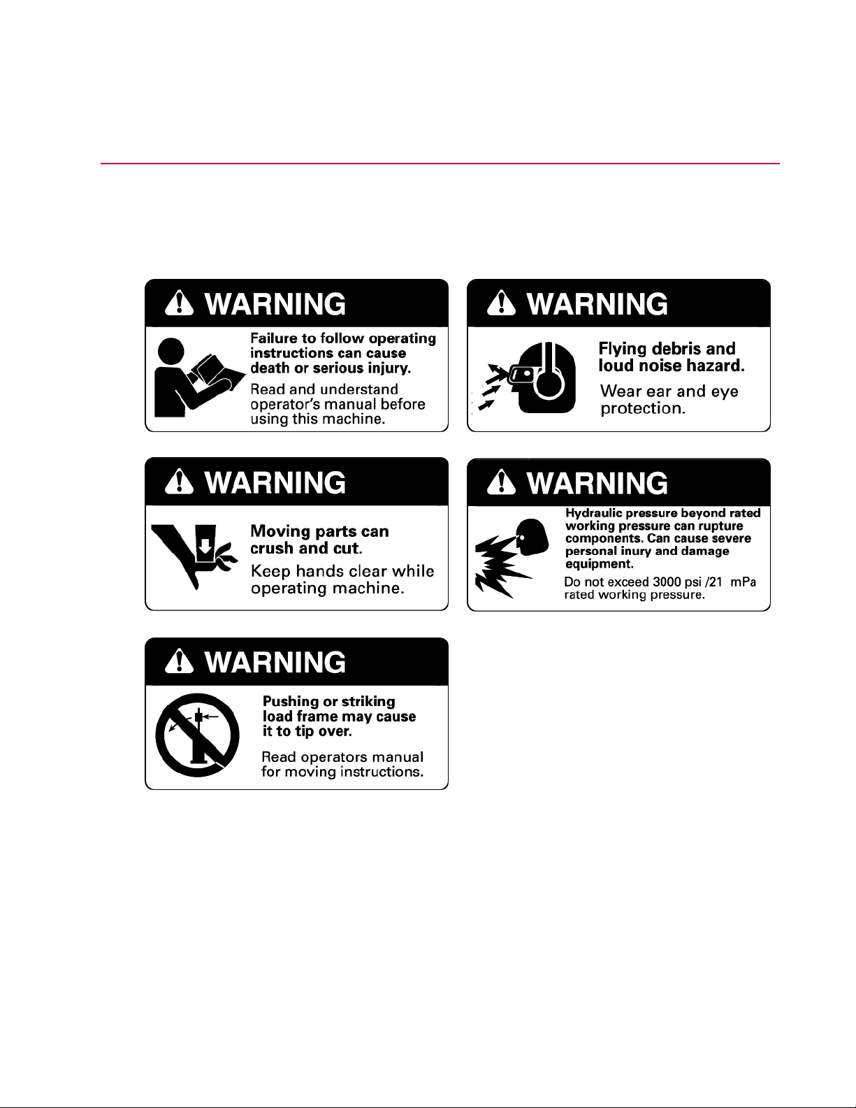
Load Unit Hazard Labels
Two sets of labels are used for the load frames: one set for North America and one set for rest of the world.
Hazard Labels North America (part number 100-164-553)
Safety
MTS Landmark Test System Operation | 23
Page 24
Safety
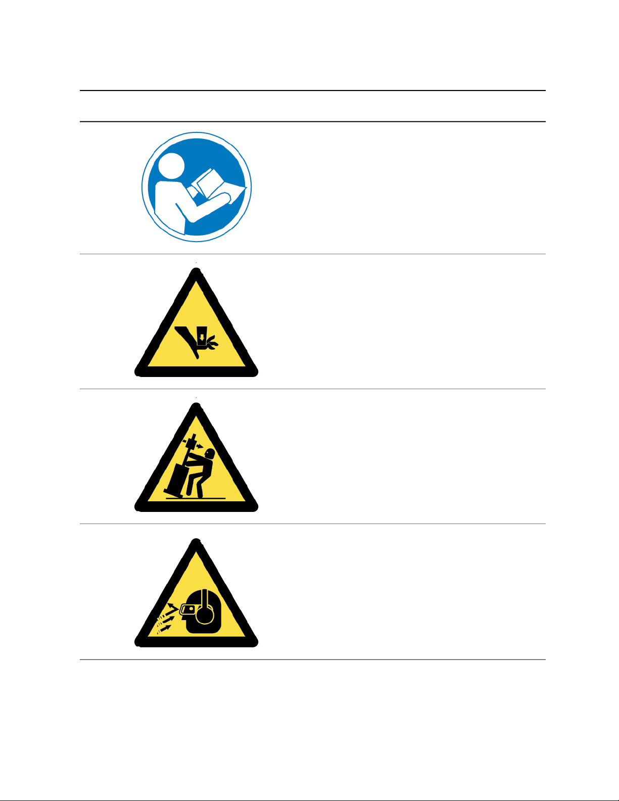
Hazard Labels Rest of World (part number 100-164-565)
DescriptionIcon
Failure to follow operating instructions can cause
death or serious injury.
Read and understand the operator’s manual before
using this machine.
Moving parts can crush and cut.
Keep hands clear while operating machine.
Pushing or striking load frame may cause it to tip
over.
Read the operator’s manual for moving instructions.
Flying debris and loud noise hazard.
Wear ear and eye protection.
24 | MTS Landmark Test System Operation
Page 25
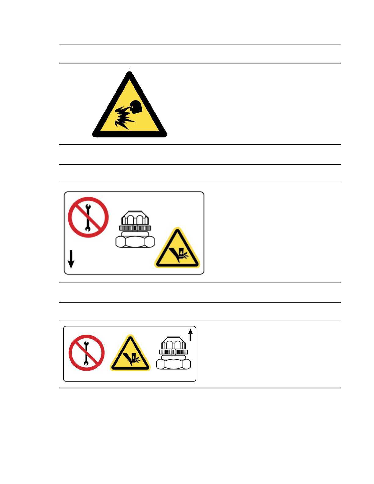
Hazard Label for HSM Needle Valve Adjustment
Safety
DescriptionIcon
Hydraulic pressure beyond rated working pressure
can rupture components, cause severe personal
injury, and damage equipment.
Do not exceed 21 MPa (3000 psi) rated working
pressure.
DescriptionIcon
The HSM needle valve is factory adjusted and
should not be adjusted in the field except by MTS
Field Service Engineers.
Hazard Label for HSM Needle Valve Adjustment
DescriptionIcon
The HSM needle valve is factory adjusted and
should not be adjusted in the field except by MTS
Field Service Engineers.
MTS Landmark Test System Operation | 25
Page 26

Page 27

System Introduction
Topics:
•
About This Manual.............................................................................................................................28
•
About Other MTS Documentation.....................................................................................................28
•
System Overview...............................................................................................................................29
•
Load Frame Overview.......................................................................................................................30
•
Load Frame Controls Overview.........................................................................................................31
•
Software Introduction.........................................................................................................................33
MTS Landmark Test System Operation | 27
Page 28

System Introduction
About This Manual
This manual is for operators of MTS Landmark Systems. It describes the following for a typical MTS
Landmark System:
• Primary components
• Key concepts you should know before using your system
• Detailed instructions for running the Example Tension Test file (included with your system) on a typical
system
• Best practices for running the example test and other tests on systems that are configured differently
than the typical system used as an example in this manual
This manual does not include information that pertains to specialists who install, calibrate, set system
preferences, create test design files, or perform other activities typically performed by Field Service
Engineers, Test Designers, and Administrators.
About Other MTS Documentation
Hardware Manuals
Your system includes a System Documentation CD that contains manuals for the individual hardware
components in your system (for example, the MTS Series 370 Load Frame manual). Use these manuals
to obtain operator information for components in your system not covered in detail in this manual.
Software Help
Your system includes software help files for each MTS software application included with your system,
usually accessible by pressing the F1 key.
Documentation Access on MTS.com
You can obtain the latest versions of standard MTS documentation on the web at
http://www.mts.com/en/services/index.htm.
28 | MTS Landmark Test System Operation
Page 29
System Overview
System Introduction
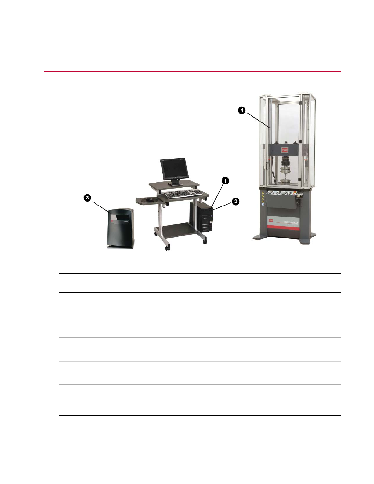
Station Components
DescriptionNameItem
1
2
MTS FlexTest (Series 793)
controller software - Station
Manager application
MTS TestSuite software - MTS
TW Express application
Controller3
MTS Landmark Load Frame4
MTS FlexTest software enables you to control the
load frame via the controller from the user interface
PC. This manual focuses on the use of the MTS
FlexTest Station Manager Application that is used
for station setup.
MTS TestSuite TW Express software enables you
to run material tests and generate reports.
The controller provides the necessary interface
between the PC and the load frame.
The electromechanical machine is used to apply
forces to specimens in order to test their material
properties.
MTS Landmark Test System Operation | 29
Page 30
System Introduction
Load Frame Overview
Introduction
The load unit consists of the load frame plus additional parts, such as hydraulic crosshead lifts and control
modules. Load units come in different sizes and configurations. The following illustration shows a typical
load unit with common accessories.
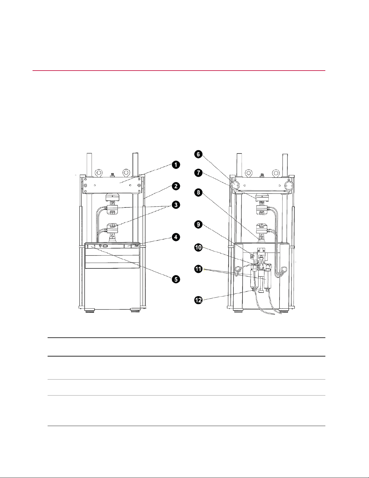
Component Identification
Load Frame Front and Rear View
Crosshead1
Grips3
30 | MTS Landmark Test System Operation
DescriptionComponentItem
Moves up and down the columns to accommodate specimens
of different lengths.
Raises and lowers the crosshead. (Optional)Hydraulic Crosshead Lifts2
Grasp and hold the specimen in place during testing. Hydraulic
grips are shown, but there are many different kinds of devices
to hold specimens.
Page 31

System Introduction
DescriptionComponentItem
10
Load Frame Control Module4
Grip Control Module5
Force Sensor (Load Cell)7
Actuator8
Hydraulic Service Manifold
(HSM)
Accumulators11
Contains the crosshead lift controls as well as the Emergency
Stop switch.
Contains hydraulic pressure gages as well as controls to clamp
and unclamp hydraulic grips.
Clamps the crosshead to the columns. (Optional)Hydraulic Crosshead Locks6
Sends a signal proportional to the forces being applied to it back
to the interface PC via the controller. The load cell shown
measures both tensile and compressive forces.
Applies forces to specimens. A linear actuator is shown. It applies
compressive and tensile forces. Other types of actuators are
available (such as rotary actuators).
Controls the rate and direction of hydraulic fluid to the actuator.Servovalve9
Controls the application and removal of hydraulic pressure to
the load unit.
Improves the actuator's response and reduces hydraulic line
fluctuations. One accumulator connects to the pressure line, and
the other to the return line.
Displacement Sensor (LVDT)12
Measures the position of the actuator. The sensor is mounted
inside the actuator.
Load Frame Controls Overview
Control Panel
The controls for the Series 370 MTS Landmark Load Unit are located on a module mounted to the front
of the load unit. The following control panel is shown with all available options. The control panel on your
load unit might not have all of these controls depending on your specific configuration.
MTS Landmark Test System Operation | 31
Page 32

System Introduction
Series 370 Load Unit Controls
DescriptionControlItem
1
2
4
5
Upper Hydraulic Grip
Controls
Lower Hydraulic Grip
Controls
Grip Pressure Adjust3
Hydraulic Crosshead
Lock/unlock Control
Hydraulic Crosshead
Positioning Control
Item 1 controls clamping and unclamping the optional upper
hydraulic grip. Item 1A adjusts the upper grip clamping rate. Item
1B is the upper grip pressure gage.
Item 2 controls clamping and unclamping the optional lower
hydraulic grip. Item 2A adjusts the lower grip clamping rate. Item
2B is the lower grip pressure gage.
Adjusts the amount of hydraulic pressure to the grips. The
adjustment range is 1–21 MPa (100–3000 psi) or 1–69 MPa
(100–10,000 psi). The highest pressure setting depends on the
maximum pressure setting. Adjust the control clockwise to increase
the hydraulic pressure. Use the pressure gage and the grip manual
to determine the necessary clamping force.
Optional control that locks and unlocks the crosshead. The
crosshead must not be moved while it is clamped. Load frames
without hydraulic locking require you to loosen and tighten
crosshead fasteners to unlock and lock the crosshead.
Optional control that raises and lowers the crosshead. The
crosshead must not be moved while it is locked. Load frames
without hydraulic positioning require you to use a hoist to support
and move the crosshead.
Emergency Stop (E-Stop)6
32 | MTS Landmark Test System Operation
Removes the hydraulic power and stops the test program. Press
this button to remove hydraulic power, and twist the switch clockwise
to release it. Use the Emergency Stop button to shut down your
test if something unexpected should happen.
Page 33

System Introduction
DescriptionControlItem
7
Switch
Controls actuator velocity. There are two positions:Actuator Velocity Limiting
• One for reduced fluid flow to the actuator, resulting in slow speed
of the actuator rod for specimen installation.
• One for full fluid flow, resulting in normal, high-speed testing
operation.
Software Introduction
Running a test on an MTS Landmark load frame system typically requires the use of the following two
MTS software programs:
MTS FlexTest (Series 793) Controller Software
You primarily use MTS FlexTest controller software to set up the station for testing. While there are a
number of applications that are part of MTS FlexTest software, this manual focuses on using the Station
Manager application to set limits, display sensor data, and move the actuator for specimen installation.
MTS TW Express Application
The MTS TW Express (TWX) application is a light version of the MTS TW Elite application and is designed
specifically for test operators. Operators primarily use MTS TWX to run tests and generate reports.
MTS FlexTest (Series 793) Controller Software - Station Manager Application
Purpose
The Station Manager application is primarily used to set up your station for a test. The major tasks necessary
to prepare the station for the Example Tension Test include:
• Opening a station
• Using the main window to open other windows
• Setting limits
• Setting up meters
• Setting up a scope
• Applying power to the station
• Moving the actuator (for specimen installation)
• Using the function generator
• Setting tuning parameters
MTS Landmark Test System Operation | 33
Page 34

System Introduction
Opening a Station
Using the Open Station window, you can select a configuration and a parameter set. You can also select
an interlock chain, although it is common practice to select Interlock 1.
Using the Main Window to Open Other Windows
While the main window provides access to nearly all of the Station Manager application's functionality, the
Example Tension Test and most other tests require only limited interaction with the main screen. Common
access points to other windows used in the Example Tension Force Test are outlined in red.
34 | MTS Landmark Test System Operation
Page 35

System Introduction
Setting Limits
Setting limits helps prevent specimen damage and injury. You can set limits using the Limits tab in the
Station Setup window.
Setting Up Meters
Meters allow you to monitor displacement and forces. Using the following windows, you can set up multiple
meters and arrange them to your liking. Meter types include Timed, Running Max/Min, and Peak/Valley.
MTS Landmark Test System Operation | 35
Page 36

System Introduction
Applying Power to the Station
The interlock and power sections of the main window are located together for convenience. There, you
can reset or override interlock conditions as well as power up the hydraulic pump unit (HPU) and hydraulic
service manifold (HSM).
Moving the Actuator
During setup, you must move the actuator so that you can clamp the specimen in the grip. The Manual
Command window allows you to move the actuator directly, or in fine or super fine increments.
36 | MTS Landmark Test System Operation
Page 37

System Introduction
Setting Up a Scope
The scope provides a graphical display of the channels of your choosing. During station setup, the scope
is often used to compare the input signal to the feedback signal. This activity is essential to setting tuning
parameters and helps ensure good system response.
Using the Function Generator
The function generator allows you to input a signal to the specimen so that you can monitor the feedback.
This is necessary when tuning the system. The controls for the function generator are found in the main
window.
Setting Tuning Parameters
The tuning fork icon (boxed in red) found in the Station Setup window provides access to the tuning tabs.
You can enter tuning parameters on the Adjustments tab.
MTS Landmark Test System Operation | 37
Page 38

System Introduction
MTS TW Express (TWX) Application
Common Windows
When running tests, you can expect to perform many of the activities shown in the list below. This section
introduces you to the software screens associated with those activities.
Test Activities
• Selecting a test
• Clearing interlocks
• Running the test
• Entering variable values
Review, Analysis, and Reporting Activities
• Comparing test runs
• Excluding test runs
• Adding and ordering data fields
• Showing additional statistical data
• Configuring charts
• Switching views
• Adjusting variables and recalculating results
• Saving display configurations
• Generating a report
Selecting a Test
Selecting a test can be done from the main screen as shown below, or from the File menu.
38 | MTS Landmark Test System Operation
Page 39

System Introduction
Clearing Interlocks
To clear interlocks, first correct any interlock conditions (for example, turning on the pump), and then click
the Reset button to clear any interlocks.
Running the test
The buttons in the Test Controls panel allow you to run a test. Use the green arrow (Run the Test) button
to start a test.
Entering Variable Values
The test designer may have added prompt dialogs for variable values. If so, they appear automatically as
the test is run.
MTS Landmark Test System Operation | 39
Page 40

System Introduction
Comparing Test Runs
Select the Compare checkbox next to a test run to see the test run in the graph.
Excluding Test Runs
If there is a problem with a test run, you can exclude it from calculations and statistical results by tagging
the test run.
40 | MTS Landmark Test System Operation
Page 41

System Introduction
Adding and Ordering Data Fields
Right-click anywhere in the Results panel to show the Set Result Variables window. This window allows
you to add fields to the Results panel. Once they are added, you can use the Set Variable Order window
to arrange the variables that are shown in the Results panel. Access the Set Variable Order window by
selecting Define > Variables, and then right-clicking anywhere in the Variables panel.
MTS Landmark Test System Operation | 41
Page 42

System Introduction
Displaying Additional Statistical Data
The statistical data shown in the Statistics panel can be configured using the Configure Statistics window.
Right-click in the Statistics Panel to show the Configure Statistics window.
42 | MTS Landmark Test System Operation
Page 43

Configuring Charts
Right-click a chart to configure it.
System Introduction
MTS Landmark Test System Operation | 43
Page 44

System Introduction
Switching Views
You can show up to four views at a time. If more than four views have been created, you can switch
between them by right-clicking a view and selecting Switch to View.
44 | MTS Landmark Test System Operation
Page 45

System Introduction
Adjusting Variables and Recalculating Results
You can adjust variables even after a test is run. To do so, enter the corrected value, and then press Enter
to recalculate results. This can be helpful in correcting errors or performing "what if" analysis. If you wish
to revert to the original value, simply click the Reset button.
MTS Landmark Test System Operation | 45
Page 46

System Introduction
Saving Display Configurations
Once you have the display configured the way you like it, you can save it so that you switch between
displays.
Generating a Report
You can generate an individual report for each test run, or you can produce a single report for all test runs
as shown here.
46 | MTS Landmark Test System Operation
Page 47

System Introduction
MTS Landmark Test System Operation | 47
Page 48

Page 49

Key Concepts
Topics:
•
About This Chapter............................................................................................................................50
•
Understanding Your MTS Software...................................................................................................50
•
Understanding MTS File Types.........................................................................................................52
•
Understanding the Control Loop........................................................................................................55
•
Understanding Control Channels and Control Modes.......................................................................58
•
Using Detectors and Actions to Protect Yourself and Your Equipment.............................................58
•
Using the E-Stop Control...................................................................................................................59
•
Understanding the Load Train...........................................................................................................59
•
Positioning the Crosshead to Install the Specimen...........................................................................60
•
Positioning the Actuator to Install the Specimen...............................................................................61
•
Optimizing System Response Before Testing...................................................................................61
•
Understanding and Resolving Error Conditions................................................................................61
MTS Landmark Test System Operation | 49
Page 50

Key Concepts
About This Chapter
This chapter, as well as the information in the Safety chapter, contains information you should know before
you attempt to run tests with your MTS Landmark System. This information applies to the typical system
used as an example in this manual.
For information that applies to other tests or system configurations, see the individual component products
manuals included in the System Documentation found under the Start Menu on the user interface PC.
Understanding Your MTS Software
Your MTS controller includes two software packages, both of which you must use to set up and run tests:
• MTS FlexTest controller software to set up your station
• MTS TestSuite test software to run tests on your station
MTS FlexTest Controller Software and the Station Manager Application
MTS FlexTest software (also referred to as MTS 793 software) includes several applications including
Station Builder, Project Manager, Hwi Editor, and so on are accessible from the Start menu or desktop
icons.
MTS FlexTest (Series 793) Controller Software Start Menu Directory and Desktop Icon
It is important to understand that to set up your station for running tests, the only MTS FlexTest
software you need is the Station Manager application.
Some of the setup activities you perform on your station with the Station Manager application include:
• Setting limits and actions to protect yourself and the equipment
• Applying hydraulic pressure to the station
• Positioning the actuator to install the specimen
50 | MTS Landmark Test System Operation
Page 51

Key Concepts
• Offsetting the weight of fixtures so those values do not appear in test data
• Adjusting gain to optimize system response
MTS TestSuite Test Software and the MTS TW Express application
MTS TestSuite software includes several applications. Depending on your installation, MTS TW Elite, MTS
TW Express, and so on are accessible from the Start menu or desktop icons.
MTS TestSuite Testing Software Start Menu Directory and Desktop Icon
It is important to understand the following:
• To run tests on your station, the only MTS TestSuite software you need is the MTS TW Express
application (or TWX for short).
Note: The MTS TW Elite application can be configured for operators. In that configuration, it has
the same capabilities as the MTS TW Express application.
• TWX operates in parallel with the Station Manager application. So while running tests, you must keep
the MTS FlexTest Station Manager application operating at all times to maintain control of the system.
(You typically minimize the Station Manager application after using it to set up your station.)
• You typically go back-and-forth between using TWX and the Station Manager application when running
tests. This means you must minimize and maximize their interfaces depending on what you need to
do. For instance, when you have completed preparation of your station, you minimize the Station
Manager application. Then you launch TWX, select a test, and start the first test run of the test. When
the test run is complete, you minimize TWX, and maximize the Station Manager application to load
another specimen. Then you minimize the Station Manager application, maximize TWX, start another
test run, and so on.
MTS Landmark Test System Operation | 51
Page 52

Key Concepts
Switching Between Station Manager and TWX When Running Tests
DescriptionItem
Station Manager Main Window1
Task Bar2
Set Up Tests Using the Station Manager Application3
TWX Main Window4
Station Manager Minimized on Task Bar5
6
Run Tests Using TWX and the Station Manager
Application
Understanding MTS File Types
File Types
When setting up and running tests, you interact with a number of different file types:
52 | MTS Landmark Test System Operation
Page 53

Key Concepts
Station File Types
DescriptionFile Type
MTS FlexTest Project Files
MTS TestSuite Project
Files
Configuration Files
A FlexTest project is a collection of files related to the station configuration.
When you open a configuration, it opens in the context of its parent project.
Files associated with configurations, such as sensor calibration files and
parameter sets, are linked to configurations within the project directory.
FlexTest projects are not associated with MTS TestSuite projects.
An MTS TestSuite project is a collection of file path settings related to TW
Test Procedures. When you open a test, it opens in the context of its parent
project. Files associated with tests, such as external files and report templates,
are linked to tests with project settings. MTS TestSuite projects are not
associated with FlexTest projects.
A Station Configuration file (.cfg) defines the controller resources allocated
to a particular station. The following figure illustrates how the configuration
file you open to perform the Example Tension Test relates to the station.
Parameter Sets
Sensor Calibration Files
Station Configuration Files Define Physical Station Resources
A Parameter Set is a collection of information that optimizes how the
components of your configuration work together to suit your test requirements.
A Parameter Set is not a discrete file; it is information that is saved with the
configuration. Parameters Sets include everything from tuning values to
detector settings. When you change these settings from their default values,
you create a unique Parameter Set for your Station Configuration.
Sensor Calibration files (.scf) contain information about system sensors,
including model number, date, calibration type, and conditioner information.
You use the Station Manager application to select Sensor Calibration files
for your Station Configuration. Sensor Calibration files are part of the
Parameter Set.
MTS Landmark Test System Operation | 53
Page 54

Key Concepts
DescriptionFile Type
Test Template Files
Test Procedure Files
Reports
Creating and Modifying Parameter Sets
Test Template files are command files created with TW Elite for performing
tests on Station Configurations. Test Template files contain only test definition
information.
Test Procedures files are similar to Test Template files, but include a container
that stores test data and results. You can create a Test Procedure file from
scratch, or by selecting a Test Template file, which automatically copies the
test definition information and adds a container for test data.
When you run a test report, data is sent from MTS TestSuite TW Express to
an Excel spreadsheet. The spreadsheet can be viewed even if you do not
have Excel on the interface PC using the Excel viewer.
MTS TestSuite Test Template Icon
MTS TestSuite Test Procedure Icon
You use the Station Manager application to create and modify parameter sets. Parameter Sets define the
operational characteristics of the resources in your station. You can create up to 15 Parameter Sets per
configuration.
Concept of the Station Manager Application Creating a Parameter Set
Selecting and Saving Parameter Sets
You select a Parameter Set when you open your Station Configuration. It is a good idea to save your
parameter set periodically during station setup as you make changes in the Station Manager application.
Concept of a Station Configuration File Paired with a Parameter Set
54 | MTS Landmark Test System Operation
Page 55

Key Concepts
How MTS Files Work Together
The basic workflow is as follows:
• You use the Station Manager application to open a Station Configuration.
• You select a Parameter Set (which includes specific Sensor Calibration files) for your Station
Configuration.
• You use the Station Manager application to optimize your Station Configuration for the test you desire
to run.
• While keeping the Station Manager application running, you use the TW Express application to select
the Test Procedure appropriate for your test.
• You start the test with the TW Express application.
• You create a Test Report with the TW Express application.
Using MTS Applications and Files to Run Tests
Understanding the Control Loop
MTS Landmark Test Systems use closed-loop control, and understanding it lays a foundation for many of
the topics in this document. Closed-loop control is a basic servomechanism concept of controlling a test,
in which a controlling element controls a controlled element.
Closed Loop Control Concept
DescriptionItem
Feedback1
MTS Landmark Test System Operation | 55
Page 56

Key Concepts
DescriptionItem
Controlling Element2
Controlled Element3
Command4
The controlling element is the computer, the digital controller, and the MTS Station Manager application.
The controlling element produces a control signal (Command) that represents the direction and amount
of force the actuator should apply to the specimen. The controlled element comprises the servovalve, the
hydraulic actuator, and the specimen itself. The controlled element applies the required forces (Command)
to the specimen and the specimen reacts to it. The Feedback is the response from one of various sensors
that indicates how the controlled element has responded.
Closed Loop Control Step-by-Step
The following closed-loop diagram illustrates how the system operates when you use the Manual Control
panel in the Station Manager application to apply a compressive force to the specimen. Assume that the
system is in Force Control.
56 | MTS Landmark Test System Operation
Page 57

Key Concepts
Basic Closed-Loop Control in MTS Landmark Systems
1. You input a compressive command by adjusting the Manual Command slider control in the Station
Manager application.
2. The Station Manager application (program source) instructs the digital controller to generate a signal
that represents the direction and amount of force the actuator needs to apply to the specimen to
accommodate your command.
3. The digital controller generates this command and sends it to the servovalve. The servovalve spool
opens and allows more high-pressure hydraulic fluid (from the Hydraulic Power Supply) to push on the
actuator that is attached to the lower grip.
4. The actuator moves and compresses the specimen.
5. The force transducer (load cell) senses the amount of compression and sends this feedback to the
digital controller, where it is compared with your command.
The system automatically repeats Steps 2 through 5 until the desired command is achieved. The digital
controller continues to generate commands to the servovalve to maintain the commanded force on the
specimen.
MTS Landmark Test System Operation | 57
Page 58

Key Concepts
Understanding Control Channels and Control Modes
Control Channel (For example, Actuator)
Control channels command actuator movement by providing a valve driver signal to the servovalve. The
servovalve causes the actuator to move, which applies forces to the specimen.
Control Modes (For example, Force or Displacement)
A control channel includes one or more control modes. Control modes determine how the commanded
force is applied to the specimen. Control modes typically include force and displacement. Only one control
mode can be active at a time per control channel.
Using Control Modes
When setting up your station for testing, you will select control modes at various times, such as;
• When using the Manual Command panel to position the actuator to install and remove the specimen
• When using the Station Setup window to optimize system response
When you start a test, you lose the ability to select control modes manually. The controller automatically
switches to the control mode selections programmed into the test procedure.
Control Mode Example
Suppose you want to compress your specimen using the Manual Command panel.
• If you choose force control, the test system will apply a compressive force to your specimen in terms
of Newtons (or pounds) of force. If you enter a 1000 Newton command and the specimen is relatively
soft, the actuator will travel several millimeters (or inches) to achieve the command. Likewise, If you
apply the same command and the specimen is relatively hard, the actuator will travel a fraction of that
distance to apply the same force.
• If you select displacement control, the test system will move the actuator in terms of millimeters (or
inches) of displacement. If you apply a 10 millimeter command to a soft specimen, the actuator may
apply only a small force to the specimen to achieve the command. If you apply the same command to
a hard specimen, the actuator will apply a much greater force to apply the same displacement.
Using Detectors and Actions to Protect Yourself and Your Equipment
When set properly, MTS FlexTest detectors can minimize the risk of injury to yourself and damage to the
specimen. They can also inform you when something wrong or unexpected occurs, and let you know when
something you expect to occur, such as the specimen failing, actually occurs.
58 | MTS Landmark Test System Operation
Page 59

Key Concepts
Sensor Limits
One type of detector is a limit detector for sensor input signals. Each sensor can have a high and a low
limit which you can enable separately. When a sensor exceeds (or trips) its upper or lower limit, the selected
detector action occurs.
Detector Actions
The effect a tripped detector has on the system depends on the action you select. The action may result
in the removal of hydraulic pressure from the station, the program stopping, an entry written to the Message
Log, and various other actions you can select.
Setting Limits Before Specimen Installation
Before installing the specimen, it is best practice to set upper and lower force limit detectors to levels that
protect the specimen from damage and minimize the risk of injury to yourself, and to set the action to
"Interlock." For instance, in the Example Test, before you install the specimen you set the maximum tensile
force to 5,000 N (5 kN) to protect the specimen from excessive gripping force. You also set the maximum
compressive force to -50 N (-0.05 kN) to reduce the risk of injury due to a compressive force while working
in close proximity to the actuator.
Setting Limits Before Testing
After the specimen is installed and you are ready to run the test, it is best practice to adjust the upper and
lower force limit detectors to levels that will not interfere with forces that the test procedure is designed to
apply to the specimen. In general, this means you will extend detector limits values. For instance, in the
Example Test, before you run the test you adjust the maximum tensile force to 15,000 N (15 kN), and the
maximum compressive force to -1,000 N (-1 kN). In this case, if you did not adjust the force detector levels
from the levels set before installing the specimen, the detectors would trip as soon as you start the test.
Using the E-Stop Control
If something unusual occurs that requires immediate action, use the Emergency Stop (E-Stop) control to:
• Stop whatever setup operation or test you have in progress, and
• Remove hydraulic pressure from the station.
While using your system, always keep in mind where the E-Stop control is and what it does. The E-Stop
control is located on the load frame control panel. It is a large red button on a yellow striped background.
The emergency stop switch stays activated until you twist the knob as indicated by the arrows.
Understanding the Load Train
It is important to understand the components in the load train. When installing and removing the specimen
and performing test setup, you interact with elements of the load train.
For load frames with base mounted actuators (as used by the typical system in this manual), the load train
consists of all the components between the actuator’s piston rod (the component that moves up and down)
MTS Landmark Test System Operation | 59
Page 60

Key Concepts
and the crosshead. This typically includes the lower grip, the specimen, the upper grip, and the force
sensor (load cell), as shown.
Typical Components in the Load Train
DescriptionItem
Force Sensor (Load Cell)1
Spiral Washers2
Upper Grip3
Specimen4
Lower Grip5
Connector Stud6
Actuator7
Positioning the Crosshead to Install the Specimen
It is best practice to position the crosshead to accommodate the specimen and fixturing while ensuring
minimal movement away from the mechanical center. In general, once you position the crosshead, additional
adjustments are not needed unless a component in the load train changes dimensions substantially. On
60 | MTS Landmark Test System Operation
Page 61

Key Concepts
the load frame used in the typical system in this manual, you use the hydraulic lift and lock controls on the
load frame control panel to position the crosshead.
Positioning the Actuator to Install the Specimen
You typically position the actuator every time you install a specimen. On the typical system used as an
example in this manual, you use the Manual Command panel in the Station Manager application to position
the actuator. If your system includes a Model 494.05 Handset, you can also position the actuator using
the handset.
Optimizing System Response Before Testing
Optimizing system response is referred to as tuning.
Why Tuning Is Beneficial
Tuning optimizes system response by adjusting the system so that its servoloop responds accurately to
its command signal. When you tune, you are setting the stability and optimizing the response of the
servocontrol loop. Proper tuning improves the performance of your MTS system in the same way that
performing a tune-up on an automobile improves its performance.
Loop Tuning for the Example Test
In the example test you adjust tuning at two points in the procedure:
Setting Initial Values to Ensure Stability
The first point is before you install the specimen or apply hydraulic pressure to the station. The purpose
is to ensure servoloop stability. In this case you simply set tuning controls to conservative values.
Adjusting Values to Optimize Performance
The second point is after you install the specimen, but before you run the test. The purpose is to optimize
system performance with the specimen in the loop. In this case you apply a cyclic waveform command
and adjust tuning parameters so that the feedback (system response) is as close to the system command
as possible. When this is achieved, the system response is optimized for that particular specimen. If you
want to test a different specimen that has different performance characteristics, you will have to adjust
tuning values for the new specimen.
Understanding and Resolving Error Conditions
Resolving error conditions is a normal part of operating an MTS Landmark System. You typically identify
and resolve several error conditions during setup and testing.
Example
MTS Landmark Test System Operation | 61
Page 62

Key Concepts
When you launch the Station Manager application and open a configuration, the configuration opens in
an interlocked state by design. To help you identify this error condition, the system lights the Interlock
indicator in the main window, and also writes a “Software Interlock” entry into the Message Log, To resolve
this condition, click the Reset button in the Station Manager main window.
Using Application Logs to Identify Error Conditions
Both the Station Manager and MTS TestSuite TWX applications are equipped with logs to help you identify
error conditions. These logs are your window into the state of the system, and your information center for
the source of error conditions. Each log entry is categorized with key words such as “Warning” and “Error”
to inform you if intervention is required. For quick reference, the Station Manager application includes a
Message Pane, and the MultiPurpose Express application includes an Error List and Application Log that
displays log file entries as they occur.
62 | MTS Landmark Test System Operation
Page 63

Running the Example Tension Test
Topics:
•
About This Chapter............................................................................................................................64
•
Test Procedure Overview..................................................................................................................64
•
Prepare for Specimen Installation.....................................................................................................65
•
Install the Specimen..........................................................................................................................77
•
Prepare to Run the Test....................................................................................................................86
•
Run the Example Tension Test..........................................................................................................98
•
Remove the Specimen....................................................................................................................105
•
Recover from a Tripped Limit..........................................................................................................110
MTS Landmark Test System Operation | 63
Page 64

Running the Example Tension Test
About This Chapter
This chapter describes how to set up and run the MTS SH Tension Test (Simplified) using the typical MTS
Landmark system shown in the System Overview section.
Adapting This Chapter to Your System
If your system contains the same components as the typical system described in this manual, you can
follow the instructions without modification to run the Example Tension Test. In some cases, your system
may vary from the typical system shown. For instance, you may have a table-top load frame instead of
the stand-up model, or manual crosshead locks instead of hydraulic crosshead locks. If this applies, you
can still run the Example Tension Test on your system by referring to the appropriate information in the
individual component product manuals included on the System Documentation CD that accompanies your
system
Test Procedure Overview
The following is an abbreviated version of the complete Example Tension Test procedure. You may find
it helpful as a checklist or as a useful reference once you are somewhat familiar with the process.
1. Prepare for Specimen Installation
a)
Turn on the Station (p. 65)
b)
Open the Station Manager Application (p. 66)
c)
Verify Calibration Files (p. 68)
d)
Set Up Meters for Specimen Installation (p. 69)
e)
Set Limits for Specimen Installation (p. 72)
f)
Zero the Force Signal (p. 74)
g)
Set Initial Tuning Parameters (p. 75)
2. Install the Specimen
a)
Power up the Pump and HPU (p. 78)
b)
Position the Actuator Using Displacement Control (p. 79)
c)
Zero Displacement (p. 80)
d)
Clamp the Specimen in the Lower Grip (p. 81)
e)
Position the Crosshead (p. 82)
f)
Move the Specimen into the Upper Grip Using Displacement Control (p. 83)
g)
Switch to Force Control (p. 84)
h)
Clamp the Specimen in the Upper Grip (p. 84)
i)
Check and Reset Meter History (p. 85)
3. Prepare to Run the Test
a)
Perform Basic Performance Tuning (p. 86)
b)
Switch to Peak Valley Meters (p. 94)
c)
Adjust Limits for the Test (p. 95)
64 | MTS Landmark Test System Operation
Page 65

d)
Show Station Manager Scope and Meters for the Test (p. 96)
e)
Minimize Station Manager (p. 97)
4. Run the Test
a)
Open the TWX Application (p. 98)
b)
Select the Test (p. 100)
c)
Switch to Round Specimen Geometry (p. 100)
d)
If Necessary, Correct Any Resource Errors (p. 101)
e)
Run the Test (p. 103)
f)
Review the Results (p. 104)
g)
Save the Test and Minimize TWX (p. 104)
5. Remove the Specimen
a)
Remove Displacement Limits (p. 105)
b)
Switch to Running Max/Min Displacement and Force Meters (p. 106)
c)
If Appropriate, Remove the Intact Specimen (p. 107)
d)
If Appropriate, Remove the Broken Specimen (p. 109)
6. Recover from a Tripped Limit
a)
If Necessary, Recover from a Tripped Force Limit (p. 110)
b)
If Necessary, Recover from a Tripped Displacement Limit (p. 113)
Running the Example Tension Test
Prepare for Specimen Installation
Preparing for specimen installation consists of the following tasks:
a)
Turn on the Station (p. 65)
b)
Open the Station Manager Application (p. 66)
c)
Verify Calibration Files (p. 68)
d)
Set Up Meters for Specimen Installation (p. 69)
e)
Set Limits for Specimen Installation (p. 72)
f)
Zero the Force Signal (p. 74)
g)
Set Initial Tuning Parameters (p. 75)
Turn on the Station
1. Turn on the computer.
2. Turn on the controller.
MTS Landmark Test System Operation | 65
Page 66

Running the Example Tension Test
The controller power switch is located on the back of the controller.
Open the Station Manager Application
1. Close any open applications on the computer desktop.
This prevents possible confusion from having multiple stations open.
2. Select All Programs > MTS 793 Software > Station Manager. This launches communication between
the computer and the MTS controller.
3. If necessary, select a project.
It is common practice to keep all files in Project1. If you find this acceptable, at the Select Project
window, select Project1. Otherwise enter your own project name for the project.
Note: The Select Project window will not appear if you selected Project1 as the default project
when you installed the MTS TestSuite application.
4. If necessary, select a controller.
In the Controller Selection window, select the controller for the station that you are using.
66 | MTS Landmark Test System Operation
Page 67

Note: This window may not appear in all cases.
5. Select a configuration and parameter set.
Running the Example Tension Test
Under normal circumstances, you would select a configuration file and parameter set recommended
by the experts in your lab. However, for this example test, select the Training config.cfg configuration
but do not click OK yet.
Parameter sets are found in the lower left corner of the Open Station window. For this example test,
select the hard specimen tuning parameter set and click Open. A set of windows may open based
on the last user’s window setup. Minimize any windows that appear as you will be maximizing them as
appropriate.
6. Ensure that the HSM (hydraulic service manifold) is off.
MTS Landmark Test System Operation | 67
Page 68

Running the Example Tension Test
Turning the HSM off removes power from the actuator so that it cannot move unexpectedly during load
frame inspection or specimen installation.
Note: It is acceptable to leave the pump (HPU) on, as it may be needed for other stations and
also leaves power to the hydraulic grips for specimen installation.
7. Identify the current configuration and parameter set.
The configuration and parameter set currently in use is shown in the title bar of the Station Manager
application. For this test, the title bar should read "Training config.cfg: hard specimen tuning".
Verify Calibration Files
It is important to verify that the Station Manager calibration files match the load cell (force sensor) and
actuator LVDT to help ensure that you collect valid data.
1. Verify that the correct calibration file for the displacement sensor is in use.
68 | MTS Landmark Test System Operation
Page 69

Running the Example Tension Test
a) Select Station Manager > Display > Station Setup > Channels > Ch1 (or other depending on
your configuration) > Displacement.
b)
Confirm that the sensor serial number found on the Sensor tab in your software matches the LVDT
serial number found on your load frame (the tag is typically located on the back). This ensures that
your configuration file matches your hardware and that you are able to collect valid data.
2. Verify that the correct calibration file for the force sensor (load cell) is in use.
Repeat Step 1 for the force sensor by selecting Station Manager > Display > Station Setup > Channels
> Ch1 (or other depending on your configuration) > Force. (The force sensor tag is typically located
on the force sensor.)
Set Up Meters for Specimen Installation
1. Click the Meters button in the Station Manager application.
This will allow you to monitor sensor readings. Click the meter button in the Station Manager application
main window.
2. If more than one meter appears, delete the extra instances so that only one meter remains.
MTS Landmark Test System Operation | 69
Page 70

Running the Example Tension Test
To delete a meter, click the meter title bar, and then click the Delete button in the setup menu.
3. Set up a Running Max/Min Displacement Meter.
Use the following parameters:
• Meter Type — Running Max/Min
• Channel — Ch1 (or other depending on your configuration)
• Signal — Displacement
• Engineering Units — mm
A running max/min meter provides the history of sensor extremes that the meter has read since it was
last reset.
4. Set up a Running Max/Min Force Meter.
Use the following parameters:
• Meter Type — Running Max/Min
• Channel — Ch1 (or other depending on your configuration)
• Signal — Force
• Engineering Units — kN
5. Set up a Timed Displacement Meter.
70 | MTS Landmark Test System Operation
Page 71

Use the following parameters:
• Meter Type — Timed
• Channel — Ch1 (or other depending on your configuration)
• Signal — Displacement
• Engineering Units — mm
A timed meter provides the current reading of the sensor.
6. Set up a Timed Force Meter.
Running the Example Tension Test
Use the following parameters:
• Meter Type — Timed
• Channel — Ch1 (or other depending on your configuration)
• Signal — Force
• Engineering Units — kN
7. Align the meters.
Click the Align Meters button to toggle between different meter alignments. Select an alignment that
works for your window layout.
MTS Landmark Test System Operation | 71
Page 72

Running the Example Tension Test
Set Limits for Specimen Installation
You can reduce the chances of specimen damage or injury by setting limits that control the amount of
force read at the sensor. However, even with limits set, do not rely solely on the force sensor to protect
you from injury.
1. Set the displacement limits to a wide range that will not interfere with specimen installation. This is
acceptable because this Example Tension Test uses no fixturing that requires protection.
a) In the Station Manager main window, select Display > Station Setup, and click the Channel Input
Signals button.
b) Select the Displacement channel.
c) Select the Limits tab.
d) Use the following parameters:
Important: The following numbers were appropriate for the example test on a typical system.
You will need to adapt these entries to your specimen, test, and system.
• Ch1 Displacement (Upper Limit, Upper Action) — 100 mm, Interlock
• Ch1 Displacement (Lower Limit, Lower Action) — (- 100) mm, Interlock
2. Set the Force Upper (Tension) Limit.
72 | MTS Landmark Test System Operation
Page 73

Running the Example Tension Test
Note: For this test, MTS has determined that a setting of +5 kN will prevent damage to the
system and the specimen.
DescriptionItem
Type here and press Enter1
Note: You must press Enter after typing numerical entries for them to be accepted.
a) Select Station Manager > Display > Station Setup > Channels > Ch1 (or other depending on
your configuration) > Force > Limits, click the Channel Input Signals button, and then click the
Limits tab.
b) Set the Upper Limit to +5 kN (a positive number indicates tension). Be sure to press Enter after
typing in the limit.
c) Then, in the Upper Action drop-down list, select Interlock.
3. Set the Force Lower (Compression) Limit.
MTS Landmark Test System Operation | 73
Page 74

Running the Example Tension Test
For specimen installation, select a low compression limit to reduce the chance of specimen damage
or injury. While -0.05 kN is shown here as an example, you should use a limit that adheres to your lab's
specimen installation guidelines.
a) Enter -.050 kN in the Lower Limit text box (a negative number indicates compression). Be sure to
press Enter after typing in the limit.
b) Once again, select Interlock for the Lower Action.
Zero the Force Signal
1. Select Exclusive Control.
In the Station Manager application main window, select the Exclusive Control check box. This allows
control to come from either the computer software or the handset, but not both.
2. Zero the force signal.
74 | MTS Landmark Test System Operation
Page 75

Running the Example Tension Test
Upon initial setup, the force signal meter shows the weight of the grip and associated hardware.
a) Open the Inputs: Axial Force window by selecting Station Manager > Display > Station Setup >
Channels > Ch1 (or other depending on your configuration) > Force and clicking the Channel
Input Signals button.
b) Select the Offset/Zero tab and then click the Auto Offset button to zero the force meter. Notice
that the Manual Offset text box now shows the offset that was originally shown on the force meter.
3. Reset meter history.
With the force signal zeroed, resetting meter history for specimen installation allows you to track the
maximum forces to which the specimen has been subjected so that you can determine if the specimen
was damaged during installation.
Reset meter history by selecting Station Manager > Display > Meters and clicking the Reset button.
Set Initial Tuning Parameters
Initial tuning is required to ensure that the system does not go unstable and result in unwanted movements.
For this example hard specimen test, use the following steps:
1. Select the Tuning user access level.
In order to set tuning parameters, select the Tuning rather than Operator user access level.
MTS Landmark Test System Operation | 75
Page 76

Running the Example Tension Test
a) Do this by changing the drop-down selection box to Tuning in the Station Manager application main
window.
b) Enter the password Tuning (case sensitive) when prompted.
2. Set Displacement tuning parameters.
a) Open the Tuning: Ch1 Displacement window by selecting Station Manager > Display > Station
Setup > Channels > Ch1 (or other depending on your configuration) > Displacement, clicking
the Tuning Fork button, and clicking the Adjustments tab.
b) Use the following parameters for this hard specimen test:
Important: The following numbers were appropriate for the example test on a typical system.
You will need to adapt these entries to your specimen, test, and system.
• P Gain — 40
• I Gain — 1
• D Gain — 0
• F Gain — 0
• F2 Gain — 0
• Proportional FF Gain — 0
• FL Filter — Set to maximum positive value
Note: The parameters shown are for this Example Test using a hard specimen. For other
tests, we recommend initial settings based on known good settings from tests similar to the
one you are setting up to run. If you are unsure of what these initial settings should be, contact
MTS technical support.
3. Set Force tuning parameters.
76 | MTS Landmark Test System Operation
Page 77

Running the Example Tension Test
a) Similarly, open the Tuning: Ch1 Force tab by selecting Station Manager > Display > Station
Setup > Channels > Ch1 (or other depending on your configuration) > Force.
b) Use the following parameters for this hard specimen test:
Important: The following numbers were appropriate for the example test on a typical system.
You will need to adapt these entries to your specimen, test, and system.
• P Gain — 1
• I Gain — 1
• D Gain — 0
• F Gain — 0
• F2 Gain — 0
• Proportional FF Gain — 0
• FL Filter — Set to maximum positive value
4. Retain the Tuning user access level.
Leave the Operator Type selection set to Tuning because you will do more tuning once the specimen
is installed.
Install the Specimen
Installing the specimen consists of the following tasks:
a)
Power up the Pump and HPU (p. 78)
b)
Position the Actuator Using Displacement Control (p. 79)
MTS Landmark Test System Operation | 77
Page 78

Running the Example Tension Test
c)
Zero Displacement (p. 80)
d)
Clamp the Specimen in the Lower Grip (p. 81)
e)
Position the Crosshead (p. 82)
f)
Move the Specimen into the Upper Grip Using Displacement Control (p. 83)
g)
Switch to Force Control (p. 84)
h)
Clamp the Specimen in the Upper Grip (p. 84)
i)
Check and Reset Meter History (p. 85)
Power up the Pump and HPU
1. Correct any interlock conditions.
If a limit has been exceeded, seeIf Necessary, Recover from a Tripped Force Limit (p. 110) or If
Necessary, Recover from a Tripped Displacement Limit (p. 113).
2. Power up the HPU (hydraulic pump unit) and HSM (hydraulic service manifold).
Once all issues and interlocks are corrected and the crush zone is clear, power up the HPU only using
the accepted procedure for your lab. This will provide power to the grips only, making for a safer
installation of the specimen into the lower grip.
Note: HPU setups vary considerably by lab. This document describes a typical HPU setup. For
more information, consult your lab experts or system documentation.
3. Reset the interlock.
Click the Reset button. If the interlock will not reset, a condition like the enclosure door not being shut,
or the actuator velocity limiting switch being in turtle mode, is likely preventing the interlock from resetting.
78 | MTS Landmark Test System Operation
Page 79

Running the Example Tension Test
Note: All interlock conditions will not reset until the pump is on.
Position the Actuator Using Displacement Control
Position the actuator for the start of the test.
Warning:
Manual control of the actuator is required for specimen installation.
Unskilled movement of the actuator can result in equipment damage or personal injury.
Ensure that the area is clear, that you can see what you are doing, and that you have the
necessary skill to proceed safely.
1. Enable manual displacement control.
a) In the Station Manager main window, click the Manual Command button. The Manual Controls
window appears.
b) Select the following:
1. Channel — Ch1 (or other depending on your configuration)
2. Control Mode — Displacement
3. Enable Manual Command checkbox — Checked
Manual command is automatically zeroed when it is switched on to ensure that the actuator does
not move before desired.
2. Familiarize yourself with the slider control.
MTS Landmark Test System Operation | 79
Page 80

Running the Example Tension Test
Manual Command Slider Function
ExplanationDescriptionItem
Drag slider for "high gear"1
2
3
Before moving the actuator, familiarize yourself with the slider control as shown. Note that the following
controls can be adjusted by right-clicking the slider control.
3. Move the actuator to a point about 25 mm (1 in) above the bottom of its travel.
Click between ticks for "low
gear"
Click arrow for "super low
gear"
High Gear — Slider movement is proportional with
actuator movement. Use with extreme caution.
Low Gear — Incremental movement based on
settings for the slider control. Multiple incremental
movements can be made by holding down the
mouse button.
Super Low Gear — Very fine incremental movement
based on settings for the slider control. Multiple
incremental movements can be made by holding
down the mouse button.
a) Using the slider, slowly move the actuator down until it reaches the bottom of its travel.
Important: Your station setup will determine whether you have to move in the positive or
negative direction.
b) Using the slider, slowly raise the actuator about 25 mm (1 in).
Note: If you trip a limit, you may need to reset the interlock. For information on how to recover
from a tripped displacement limit, see If Necessary, Recover from a Tripped Displacement
Limit (p. 113)
Zero Displacement
Zeroing displacement at this point will allow you to return to this position after each test using the home
button so that you can install the specimen for the next test run.
1. Select Station Manager > Display > Station Setup > Channels > Displacement> Offset/Zero.
80 | MTS Landmark Test System Operation
Page 81

2. Click the Auto Offset button to zero displacement.
Clamp the Specimen in the Lower Grip
1. Clamp the specimen in the lower grip.
Running the Example Tension Test
Using a tool to hold the specimen, clamp the specimen in the lower grip using the controls on the MTS
Landmark load frame. You should position the specimen in the grip so that about 1/5th (see the following
photo) of the un-necked portion of the specimen is showing.
MTS Landmark Test System Operation | 81
Page 82

Running the Example Tension Test
Important: You should use a tool that is softer than the specimen to ensure that you do not
damage the specimen. Plastic tongs or pliers are best.
2. Reset the Force Lower (Compression) Limit.
a) Now that your hands are no longer required to be near the specimen, increase the force lower limit
to a value that will allow clamping of the specimen in the upper grip.
b) Select Station Manager > Display > Station Setup > Channels > Ch1 (or other depending on
your configuration) > Force, click the Channel Input Signals button, and then click the Limits tab.
c) Enter -1 kN in the Lower Limit text box and ensure that Interlock is selected for the Action.
Position the Crosshead
Adjust the position of the crosshead using the hydraulic controls.
82 | MTS Landmark Test System Operation
Page 83

Running the Example Tension Test
DescriptionItem
Crosshead Lock1
Crosshead Lift2
a) Unlock the crosshead clamps, and then move the crosshead up or down so that there is about 25
mm (1 in) clearance between the upper grip and the specimen.
b) Once properly positioned, reclamp with the crosshead lock control.
Move the Specimen into the Upper Grip Using Displacement Control
Displacement control is used to move the specimen into the upper grip. However, care must be exercised
to ensure that minimal force is imparted on the specimen during the process as this could affect test results.
1. Make sure the grip is open and ready to accept the specimen.
2. Use the slider controls to move the specimen up and into the upper grip.
MTS Landmark Test System Operation | 83
Page 84

Running the Example Tension Test
Important: Your station setup will determine whether you have to move in the positive or negative
direction.
Switch to Force Control
Switching to force control helps ensure that you do not impart excessive force on the specimen during
installation. Once in force control, the controller will follow your positioning commands while working to
maintain the force that you specify—in this case 0.00 kN.
1. In the Station Manager main window, click the Manual Command icon.
2. Set Control Mode to Force.
3. Set Manual Cmd to 0.00 kN.
Clamp the Specimen in the Upper Grip
Using the limits that you set earlier and having the load frame in force control during clamping help ensure
that excessive force is not imparted on the specimen during clamping. Nevertheless, there may be times
when you have to recover from a tripped limit that occurs during the clamping process. Instructions for
that situation are provided below.
1. Clamp the specimen in the upper grip.
84 | MTS Landmark Test System Operation
Page 85

Using the controls on the MTS Landmark load frame, slowly clamp the specimen in the upper grip.
2.
If necessary, recover from a tripped limit (otherwise proceed to the next step).
Clamping can result in tripping a force or displacement limit. See If Necessary, Recover from a Tripped
Force Limit (p. 110) or If Necessary, Recover from a Tripped Displacement Limit (p. 113).
Check and Reset Meter History
Running the Example Tension Test
Checking meter history after clamping the specimen in the upper grip allows you to verify that excessive
force was not applied to the specimen during clamping.
1. Check meter history.
Note: Acceptable limits are dependent on the specimen you are using for the test. For detailed
information, consult your lab experts or a materials handbook.
2. Reset meter history.
Now that specimen installation is complete, reset meter history by navigating to Station Manager >
Display > Meters and clicking the Reset button.
MTS Landmark Test System Operation | 85
Page 86

Running the Example Tension Test
Prepare to Run the Test
Preparing to run the test consists of the following steps:
a)
Perform Basic Performance Tuning (p. 86)
b)
Switch to Peak Valley Meters (p. 94)
c)
Adjust Limits for the Test (p. 95)
d)
Show Station Manager Scope and Meters for the Test (p. 96)
e)
Minimize Station Manager (p. 97)
Perform Basic Performance Tuning
Use the following guidelines for basic performance tuning.
1. Select the Tuning user access level.
Ensure that your user access level is Tuning rather than Operator. Enter the password Tuning (case
sensitive) if prompted.
2. Verify initial force tuning parameters.
a) To open the Tuning: Ch1 Force window, select Station Manager > Display > Station Setup >
Channels > Ch1 (or other depending on your configuration) > Force and then click the Tuning
Fork button.
b) Review the following parameters for this hard specimen test. The following is a good place to start
for this Example test with a hard specimen.
86 | MTS Landmark Test System Operation
Page 87

Running the Example Tension Test
• P Gain — 1
• I Gain — 1
• D Gain — 0
• F Gain — 0
• F2 Gain — 0
• Proportional FF Gain — 0
• FL Filter — Set to maximum positive value.
3. Disable manual command.
This allows the function generator to control the system.
a) In the Station Manager main window, click the Manual Command button. The Manual Commands
window appears.
b) Click to clear (uncheck) the Enable Manual Command check box.
4. Set up a force waveform using the Function Generator.
This introduces a force waveform to the specimen.
a) In the Station Manager main window, click the Function Generator button.
b) Set up a force waveform using the following parameters:
• Channel — Ch1 (or other depending on your configuration)
• Control Mode — Force
• Command Type — Cyclic
• Target Setpoint — +2 kN
• Amplitude — 1 kN
MTS Landmark Test System Operation | 87
Page 88

Running the Example Tension Test
• Frequency — 1 Hz
• Wave Shape — Ramp
• Compensator — None
Important: It is important to have Compensator set to None. If it is left on, it can negate
the function generator signal.
5. Open a Station Manager Scope.
Click the Scope button in the Station Manager main window.
6. Set up the Scope.
Set up a Scope to compare the command signal to the resulting feedback. In the Station Manager main
window, click the Signal Scope button. Enlarge the scope if necessary, and then set up the scope as
follows:
Y1 parameters:
• Channel — Ch1 (or other depending on your configuration)
• Signal — Command
• Unit — kN
• Units/div — 0.5
• Offset — 2
Y2 parameters:
• Channel — Ch1 (or other depending on your configuration)
• Signal — Force
Note: Another possible selection is Active Feedback. Active Feedback will automatically
plot your active channel (for example force or displacement).
• Unit — kN
88 | MTS Landmark Test System Operation
Page 89

Running the Example Tension Test
• Units/div — 0.5
• Offset — 2
Time:
• Trace Time — 5.0 s
7. Run the Function Generator.
Click the Program Run button to apply the force waveform to the specimen. If necessary, clear any
interlock conditions.
8. Adjust P Gain.
Insufficient P Gain
MTS Landmark Test System Operation | 89
Page 90
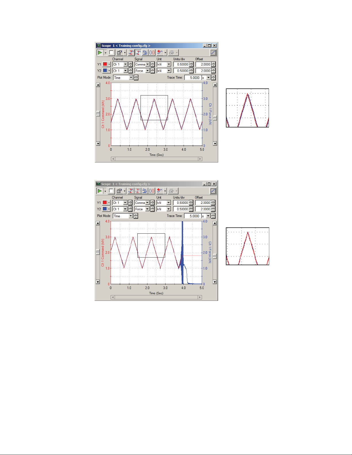
Running the Example Tension Test
Correct P Gain
a) Open the Tuning: Ch1 Force window found by selecting Station Manager > Display > Station
Setup > Channels > Ch1 (or other depending on your configuration) > Force, clicking the Tuning
Fork icon, and clicking the Adjustments tab.
b) Compare your Scope display to the preceding examples of P gain found in the following displays.
If necessary, adjust the P gain for the Force channel.
90 | MTS Landmark Test System Operation
Excessive P Gain
Page 91

Running the Example Tension Test
Note: The Scope display shows how well the feedback signal is following the command
signal. You should strive for a good match to the Correct P Gain example, realizing that perfect
adjustment is not possible.
9. Switch to the sine wave.
a) In the Station Manager main window, click the Function Generator button.
b) Stop the Function Generator by clicking the Stop button, and then change the wave shape from
ramp to Sine.
c) Click the Program Run button to run the sine wave.
MTS Landmark Test System Operation | 91
Page 92

Running the Example Tension Test
Important: Do not adjust P gain when you switch to the sine wave form, as instability could
result.
10. Adjust I Gain.
Insufficient I Gain
Correct I Gain
92 | MTS Landmark Test System Operation
Page 93

Running the Example Tension Test
Excessive I Gain
a) Navigate to the Tuning: Axial Force window found by selecting Station Manager > Display > Station
Setup > Channels > Ch1 (or other depending on your configuration) > Force, clicking the Tuning
Fork button, and clicking the Adjustments tab.
b) Compare your graph to the examples of I gain found in the following displays. If necessary, adjust
the I gain for the Force channel.
Note: Do not adjust all the way to zero or you could trip the force limit.
11. Turn off the Function Generator.
MTS Landmark Test System Operation | 93
Page 94

Running the Example Tension Test
Click the Program Stop button to turn off the Function Generator.
Switch to Peak Valley Meters
The Running Max/Min meters served well during specimen installation; however, now that you will be
applying a force waveform to the specimen, you need meters that will show you results as they change
over time. Peak/Valley meters provide a better indication of how the system is performing over time.
1. Switch Ch1 Displacement to a Peak/Valley Meter.
In the Station Manager main window, click the Meters button. Click in the title bar of the axial
displacement running max/min meter and change the Meter Type to Peak/Valley.
2. Select a Sensitivity.
Select a Sensitivity that is about 1/10th of the displayed reading.
3. Fine-tune the Sensitivity.
Proper meter sensitivity adjustment enables you to see fluctuations between cycles. When the Sensitivity
is correct, the meter will show minor fluctuations with meter updates no faster than the frequency.
94 | MTS Landmark Test System Operation
Page 95

Running the Example Tension Test
a) If you find the values in the Meters window changing at a rate less than the frequency of the Function
Generator, double the Sensitivity.
b) If you find the values changing at a rate faster than the frequency, halve the Sensitivity. Repeat this
process until you are satisfied with the results.
4. Switch Ch1 Force to a Peak/Valley Meter and adjust Sensitivity.
Use the same procedure to change the top axial force meter to Peak/Valley meter type.
Adjust Limits for the Test
Setting force limits just outside the expected values for this Example test helps prevent specimen and
equipment damage if something unexpected happens during a test run.
1. You can retain the wide displacement limit range set earlier because this example tension test uses
no fixturing that requires protection.
a) In the Station Manager main window, select Display > Station Setup, and click the Channel Input
Signals button.
b) Select the Displacement channel.
c) Click the Limits tab.
d) Use the following parameters:
MTS Landmark Test System Operation | 95
Page 96

Running the Example Tension Test
Important: The following numbers were appropriate for the example test on a typical system.
You will need to adapt these entries to your specimen, test, and system.
• Ch1 Displacement (Upper Limit, Upper Action) — 100 mm, Interlock
• Ch1 Displacement (Lower Limit, Lower Action) — (- 20) mm, Interlock
2. Adjust force limits so that they are just outside expected values for the tension test.
a) In the Station Manager main window, select Display > Station Setup, and click the Channel Input
Signals button.
b) Select the Force channel.
c) Click the Limits tab.
d) Use the following parameters:
• Ch1 Force (Upper Limit, Upper Action) — 40.00 kN, Interlock
• Ch1 Force (Lower Limit, Lower Action — (-1.00) kN, Interlock
Show Station Manager Scope and Meters for the Test
It is common practice to use the Scope and Meters from the Station Manager application to show what
is happening on the physical equipment during the test. Ensure that the Scope and Meters you set up
earlier are open and running.
96 | MTS Landmark Test System Operation
Page 97

Running the Example Tension Test
Note: Your meter readings will reflect your station and will be different from those shown.
Minimize Station Manager
The Station Manager application must be running underneath the MPX application in order to run tests.
Minimizing the Station Manager application clears the desktop while leaving it running for the MPX
application.
1. Turn Exclusive Control off by clearing the check box.
2. Minimize the Station Manager application.
MTS Landmark Test System Operation | 97
Page 98

Running the Example Tension Test
Click the minimize button in the upper right corner of the Station Manager application.
3. Verify that the Station Manager application is still running by checking for it in the task bar.
You can maximize Station Manager at any time by clicking the Station Manager button in the task bar.
Run the Example Tension Test
Running this Example Tension test consists of the following steps:
a)
Open the TWX Application (p. 98)
b)
Select the Test (p. 100)
c)
Switch to Round Specimen Geometry (p. 100)
d)
If Necessary, Correct Any Resource Errors (p. 101)
e)
Run the Test (p. 103)
f)
Review the Results (p. 104)
g)
Save the Test and Minimize TWX (p. 104)
Open the TWX Application
1. Ensure that the HSM (hydraulic service manifold) in the Station Manager application is off.
98 | MTS Landmark Test System Operation
Page 99

Running the Example Tension Test
Note: It is acceptable to leave the pump (HPU) on as it may be needed for other stations.
2. Open the TWX application by selecting All Programs > MTS TestSuite > TW Express.
Another way to open the TWX application is by clicking the TWX icon on your computer desktop.
MTS Landmark Test System Operation | 99
Page 100

Running the Example Tension Test
Select the Test
Select the MTS SH Tension (Simplified) template.
In the MTS TWX main window, select MTS Templates > TW - Hydraulic > MTS SH Tension
(Simplified) to load the test.
Switch to Round Specimen Geometry
The MTS SH Tension (Simplified) test is set up for rectangular specimen geometry. Because this example
uses a round specimen, you will need to switch to round specimen geometry.
1. In the TWX main window, select Define > Variables.
100 | MTS Landmark Test System Operation
 Loading...