


DLP™ PROJECTOR
MODEL
XD550U
XD560U
WD570U
User Manual
XD550U
XD560U
WD570U
This User Manual is important to you. Please read it before using your projector.

CAUTION
RISK OF ELECTRIC SHOCK
DO NOT OPEN
CAUTION: TO REDUCE THE RISK OF ELECTRIC
SHOCK, DO NOT REMOVE COVER (OR BACK)
NO USER-SERVICEABLE PARTS INSIDE
REFER SERVICING TO QUALIFIED SERVICE
PERSONNEL.
The lightning flash with arrowhead symbol within an equilateral triangle is intended to alert the user to the presence of uninsulated “dangerous voltage” within the product’s enclosure that may be of sufficient magnitude to constitute a risk of electric shock.
The exclamation point within an equilateral triangle is intended to alert the user to the presence of important operating and maintenance (servicing) instructions in the literature accompanying the appliance.
WARNING:
TO PREVENT FIRE OR SHOCK HAZARD, DO NOT EXPOSE THIS APPLIANCE TO RAIN OR MOISTURE.
CAUTION:
TO PREVENT ELECTRIC SHOCK, DO NOT USE THIS (POLARIZED) PLUG WITH AN EXTENSION CORD, RECEPTACLE OR OTHER OUTLET UNLESS THE BLADES CAN BE FULLY INSERTED TO PREVENT BLADE EXPOSURE.
NOTE:
SINCE THIS PROJECTOR IS PLUGGABLE EQUIPMENT, THE SOCKET-OUTLET SHALL BE INSTALLED NEAR THE EQUIPMENT AND SHALL BE EASILY ACCESSIBLE.
WARNING
Use the attached specified power supply cord. If you use another power supply cord, it may cause interference with radio and television reception.
This apparatus must be grounded.
DO NOT LOOK DIRECTLY INTO THE LENS WHEN THE PROJECTOR IS IN THE POWER ON MODE.
CAUTION
The attached power cord is to be used exclusively for this product. Never use it for other products.
EN-2

Contents |
|
Important safeguards ........................................................................................................................ |
4 |
Overview............................................................................................................................................ |
6 |
Remote control.................................................................................................................................. |
8 |
Installation ........................................................................................................................................ |
9 |
Basic connections ........................................................................................................................... |
12 |
Preparation ..................................................................................................................................... |
15 |
Basic operation ............................................................................................................................... |
16 |
Menu operation ............................................................................................................................... |
20 |
Image adjustment............................................................................................................................ |
30 |
Network settings ............................................................................................................................. |
33 |
Advanced display utilities................................................................................................................ |
38 |
Advanced features .......................................................................................................................... |
46 |
Lamp replacement .......................................................................................................................... |
50 |
Troubleshooting............................................................................................................................... |
52 |
Indicators......................................................................................................................................... |
56 |
Specifications.................................................................................................................................. |
57 |
Trademark, Registered trademark
t .BDJOUPTI JT B SFHJTUFSFE USBEFNBSL PG "QQMF *OD
t %-1 %JHJUBM .JDSPNJSSPS %FWJDF %.% BOE #SJMMJBOU$PMPS BSF BMM USBEFNBSLT PG 5FYBT *OTUSVNFOUT
t )%.* UIF )%.* MPHP BOE )JHI %FmOJUJPO .VMUJNFEJB *OUFSGBDF BSF USBEFNBSLT PS SFHJTUFSFE USBEFNBSLT PG )%.*
Licensing LLC.
t .JDSPTPGU 8JOEPXT 8JOEPXT 8JOEPXT 91 8JOEPXT 7JTUB 8JOEPXT BOE *OUFSOFU &YQMPSFS BSF registered trademarks, trademarks, or trade names of Microsoft Corporation in the U.S. and/or other countries.
t 5IF USBEFNBSL PG 1+-JOL JT USBEFNBSL BQQMJFE GPS SFHJTUSBUJPO PS SFHJTUFSFE USBEFNBSL JO +BQBO UIF 6OJUFE 4UBUFT and other countries and areas.
t $SFTUSPO 3PPN7JFX $POOFDUFE JT B USBEFNBSL PG $SFTUSPO &MFDUSPOJDT *OD
t 0UIFS CSBOE PS QSPEVDU OBNFT BSF USBEFNBSLT PS SFHJTUFSFE USBEFNBSLT PG UIFJS SFTQFDUJWF IPMEFST
EN-3

Important safeguards
Please read all these instructions regarding your projector and retain them for future reference. Follow all warnings and instructions marked on the projector.
1.Read instructions
All the safety and operating instructions should be read before the appliance is operated.
2.Retain instructions
The safety and operating instructions should be retained for future reference.
3.Warnings
All warnings on the appliance and in the operating instructions should be adhered to.
4.Instructions
All operating instructions must be followed.
5.Cleaning
Unplug this projector from the wall outlet before cleaning it. Do not use liquid aerosol cleaners. Use a damp soft cloth for cleaning.
6.Attachments and equipment
Never add any attachments and/or equipment without the approval of the manufacturer as such additions may result in the risk of fire, electric shock or other personal injury.
7.Water and moisture
Do not use this projector near water or in contact with water.
8.Accessories
Do not place this projector on an unstable cart, stand, tripod, bracket or table. Use only with a cart, stand, tripod bracket, or table recommended by the manufacturer or sold with the projector. Any mounting of the appliance should follow
the manufacturer’s instructions and should use a mounting accessory recommended by the manufacturer.
An appliance and cart combination should be moved with care. Quick stops, excessive force and uneven surfaces may cause the appliance and cart combination to overturn.
9.Ventilation
Slots and openings in the cabinet are provided for ventilation, ensuring reliable operation of the projector and to protect it from overheating. Do not block these openings or allow them to be blocked by placing the projector on a bed, sofa, rug, or bookcase. Ensure that there is adequate
ventilation and that the manufacturer’s instructions have been adhered to.
10.Power sources
This projector should be operated only from the type of power source indicated on the marking label. If you are not sure of the type of power, please consult your appliance dealer or local power company.
11.Power-cord protection
Power-supply cords should be routed so that they are not likely to be walked on or pinched by items placed upon or against them. Pay
particular attention to cords at plugs, convenience receptacles, and points where they exit from the appliance. Do not put the power cord under a carpet.
12.Overloading
Do not overload wall outlets and extension cords as this can result in a fire or electric shock.
13.Objects and liquids
Never push objects of any kind through openings of this projector as they may touch dangerous voltage points or short-out parts that could result in a fire or electric shock. Never spill liquid of any kind on the projector.
14.Servicing
Do not attempt to service this projector by yourself. Refer all servicing to qualified service personnel.
15.Damage requiring service
Unplug this projector from the wall outlet and refer servicing to qualified service personnel under the following conditions:
(a)If the power-supply cord or plug is damaged.
(b)If liquid has been spilled, or objects have fallen into the projector.
(c)If the projector does not operate normally after you follow the operating instructions. Adjust only those controls that are covered by the operating instructions. An improper adjustment of other controls may result in damage and may often require extensive work by a qualified technician to restore the projector to its normal operation.
(d)If the projector has been exposed to rain or water.
(e)If the projector has been dropped or the cabinet has been damaged.
(f)If the projector exhibits a distinct change in performance - this indicates a need for service.
16.Replacement parts
When replacement parts are required, be sure that the service technician has used replacement parts specified by the manufacturer or parts having the same characteristics as the original part. Unauthorized substitutions may result in fire, electric shock or other hazards.
17.Safety check
Upon completion of any service or repair to this projector, ask the service technician to perform safety checks determining that the projector is in a safe operating condition.
EN-4

Important safeguards (continued)
WARNING:
Unplug immediately if there is something wrong with your projector.
Do not operate if smoke, strange noise or odor comes out of your projector. It may cause fire or electric shock. In this case, unplug immediately and contact your dealer.
Never remove the cabinet.
This projector contains high voltage circuitry. An inadvertent contact may result in an electric shock. Except as specifically explained in User Manual, do not attempt to service this product by yourself. Please contact your dealer when you want to fix, adjust, or inspect the projector.
Do not modify this equipment.
It can lead to fire or electric shock.
Do not keep using the damaged projector.
If the projector is dropped and the cabinet is damaged, unplug the projector and contact your dealer for inspection. It may lead to fire if you keep using the damaged projector.
Do not face the projector lens to the sun.
It can lead to fire.
Use correct voltage.
If you use incorrect voltage, it can lead to fire.
Do not place the projector on uneven surface.
Place the projection on a leveled and stable surface only.
Do not look into the lens when it is operating.
It may hurt your eyes. Never let children look into the lens when it is on.
Do not unplug the power cord during operation.
It can lead to lamp breakage, fire, electric shock or other trouble.
Do not touch the air outlet grilles and bottom plate.
Do not touch them or put other equipment close to the air outlet grilles because they become hot during operation. The heated air outlet grilles and bottom plate may cause injury or damage to other equipment. Also, do not put the projector on a desk that is easily affected by heat.
Do not look into the air outlet grille when projector is operating.
Heat, dust, etc. may blow out of it and hurt your eyes.
Do not block the air inlet and outlet grilles.
If they are blocked, heat may be generated inside the projector, causing deterioration in the projector quality and fire.
Do not use flammable solvents (benzene, thinner, etc.) and flammable aerosols near the projector.
Flammable substances may ignite causing fire or breakdown because the temperature inside the projector rises very high while the lamp is illuminating.
Do not use the projector with condensation on it.
It can lead to breakdown or other failure.
Place of installation
For safety’s sake, do not use the projector at any place subjected to high temperature and high humidity. Please maintain an operating temperature, humidity, and altitude as specified below.
t 0QFSBUJOH UFNQFSBUVSF CFUXFFO ¡' ¡$ BOE¡' ¡$
t 0QFSBUJOH IVNJEJUZ CFUXFFO BOE
t /FWFS QVU BOZ IFBU QSPEVDJOH EFWJDF VOEFS UIF projector to prevent the projector from being overheated.
t %P OPU JOTUBMM UIF QSPKFDUPS BU B QMBDF UIBU JT unstable or subject to vibration.
t %P OPU JOTUBMM UIF QSPKFDUPS OFBS BOZ FRVJQNFOU UIBU produces a strong magnetic field. Also refrain from installing the projector near any cable carrying a large amount of current.
t 1MBDF UIF QSPKFDUPS PO B TPMJE WJCSBUJPO GSFF surface. Otherwise it may fall, causing serious injury or damage.
t %P OPU TUBOE UIF QSPKFDUPS PO JUT FOE *U NBZ GBMM causing serious injury or damage.
t 4MBOUJOH UIF QSPKFDUPS NPSF UIBO ¡ SJHIU BOE MFGU PS ¡ GSPOU BOE SFBS NBZ DBVTF USPVCMF PS explosion of the lamp.
t %P OPU QMBDF UIF QSPKFDUPS OFBS BJS DPOEJUJPOJOH unit, heater, or humidifier to avoid hot or moist air to the exhaust and ventilation hole of the projector.
t Do not place the projector in the following places. Otherwise, a short circuit, heat generation, or melting of the power cord coating may occur, causing fire, electric shock, product failure, or deformation.
t 0VUEPPST PS OPO BJS DPOEJUJPOFE QMBDF
t 1MBDF XIFSF B HBT TVDI BT B IZESPHFO TVMmEF JT generated (i.e. hot spring)
t 1MBDF XIFSF UIFSF JT UPP NVDI TBMU TVDI BT OFBS the coast
t #F TVSF UP VTF UIJT QSPKFDUPS BU BO BMUJUVEF PG MFTT than 1500 meters.
When removing the lamp from the ceilingmounted projector
Be sure to use the lamp replacement attachment designed specifically for this projector when replacing the lamp with a new one. Lamp fragments may fall from the inside if the lamp were broken.
EN-5
Overview
11 |
3 |
1 2 |
|
|
4 |
||||||
|
|
|
|
|
|
|
|
|
|
|
|
|
|
|
|
|
|
|
|
|
|
|
|
|
|
|
|
|
|
|
|
|
|
|
|
|
|
|
|
|
|
|
|
|
|
|
|
|
|
|
|
|
|
|
|
|
|
|
|
|
|
|
|
|
|
|
|
|
|
|
|
|
|
|
|
|
|
|
|
|
|
|
|
|
|
|
|
|
|
|
|
|
|
|
|
|
|
|
|
|
|
|
|
|
|
|
|
9 |
5 8 10 |
6
7
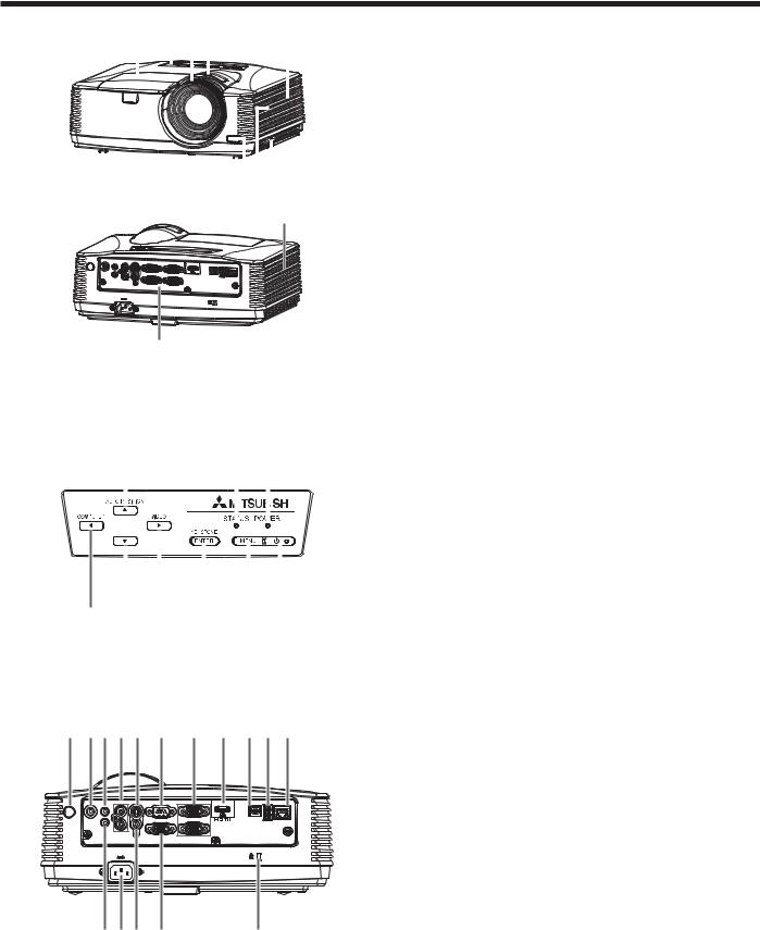
Control panel
6 |
4 |
|
|
2 |
|
|
|||||||||
|
|
|
|
|
|
|
|
|
|
|
|
|
|
|
|
|
|
|
|
|
|
|
|
|
|
|
|
|
|
|
|
|
|
|
|
|
|
|
|
|
|
|
|
|
|
|
|
|
|
|
|
|
|
|
|
|
|
|
|
|
|
|
|
|
|
|
|
|
|
|
|
|
|
|
|
|
|
|
|
|
|
|
|
|
|
|
|
|
|
|
|
|
|
|
|
|
|
|
|
|
|
|
|
|
|
|
|
|
|
|
|
|
|
|
|
|
|
|
|
|
|
|
|
|
|
|
|
7 |
8 |
9 |
5 |
3 |
1 |
1 FOCUS ring
2 ZOOM ring
3 Control panel
4 Air inlet grille
5 Remote control sensor (front)
6 Air outlet grille
7 Terminal panel
8 Speaker
9 Adjustment feet
10 Lock bar
11 Lamp cover
Caution:
t %P OPU SFQMBDF UIF MBNQ JNNFEJBUFMZ BGUFS VTJOH UIF projector because the lamp would be extremely hot and it may cause burns.
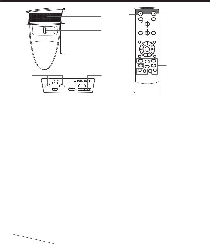
1POWER button (ON/STANDBY)
The status is changed between ON and STANDBY.
2 POWER indicator
3 MENU button
4 STATUS indicator
5 KEYSTONE/ENTER button
6 AUTO POSITION/ button
7 COMPUTER/ button
8 button
9 VIDEO/ button
Terminal panel
4 |
7 5 13 8 |
10 |
2 |
14 |
15 16 12 |
|
AUDIO AUDIO IN-3L S-VIDEO |
SERIAL |
COMPUTER / COMPONENT VIDEO |
|
USB-B USB-A LAN |
|
IN-1 |
|
|
|
|
|
AUDIO OUT |
|
IN-1 |
|
|
|
|
|
|
|
AUDIO |
|
|
|
IN-2 |
AUDIO IN-3R |
|
|
|
VIDEO |
MONITOR OUT |
IN-2 |
|
|
|
|
6 1 9 |
3 |
11 |
|
1 Power jack
2 COMPUTER IN terminal (1, 2) (mini D-SUB 15-pin) 3 MONITOR OUT terminal (mini D-SUB 15-pin)
4 Remote control sensor (rear)
5 AUDIO IN-1 terminal (mini jack)
6 AUDIO IN-2 terminal (mini jack)
7 AUDIO OUT terminal (mini jack)
8 S-VIDEO terminal
9 VIDEO terminal
10 SERIAL (RS-232C) terminal (D-SUB 9-pin) 11 Kensington Lock
12 LAN terminal (RJ-45)
13 AUDIO IN-3 terminals (L/R)
14 HDMI terminal (HDMI 19-pin)
15 USB-B terminal
16 USB-A terminal
EN-6
Overview (continued)
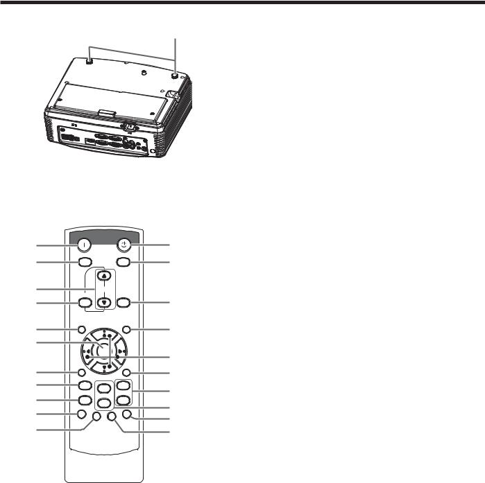
Bottom side
1
Remote control
ON |
STANDBY |
1 |
12 |
MAGNIFY |
ASPECT |
2 |
13 |
3 |
UP |
VOL |
|
KEYSTONE |
DOWN 3D |
4 |
14 |
|
AUTO |
MENU |
POSITION |
5
6
7
8
9
10
11
ENTER |
|
|
AV |
|
|
MUTE |
|
FREEZE |
VIEWER |
|
VIDEO |
1 |
|
|
COMPUTER |
|
|
UNPLUG |
|
S-VIDEO |
2 |
|
|
USB DISP. LAN DISP. |
DVI |
HDMI |
15
16
17
18
19
20
This model does not have this function.
1 Adjustment feet
1 ON button
2 MAGNIFY button
3 VOLUME UP, DOWN buttons
4 KEYSTONE button
5 MENU button
6 ENTER button
7 AV (Audio/Video) MUTE button
8 VIEWER button
9 UNPLUG button
10 USB DISP. button
11 LAN DISP. button
12 STANDBY button
13 ASPECT button
14 3D button
15 AUTO POSITION button
16 , , , buttons
17 FREEZE button
18 VIDEO, S-VIDEO buttons
19 COMPUTER (1, 2) buttons
20 HDMI button
EN-7
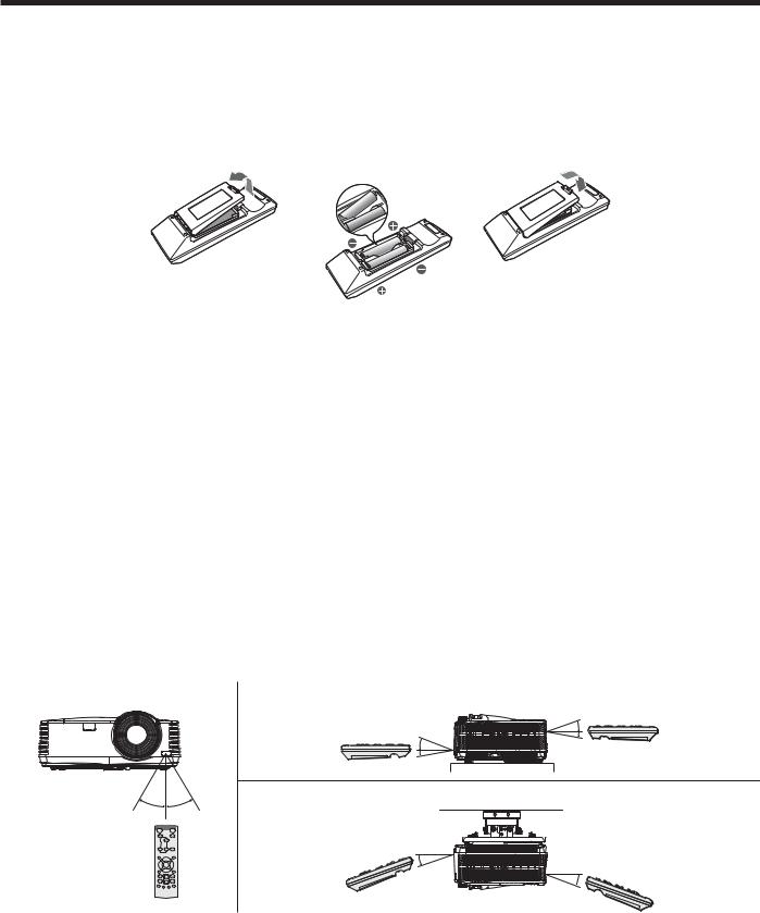
Remote control
Battery installation
Use two (AA, R6) size batteries.
Inserting the batteries into the remote control
1.Remove the back cover of the remote control by pushing the battery compartment door in the direction of the arrow.
-PBE UIF CBUUFSJFT NBLJOH TVSF UIBU UIFZ BSF QPTJUJPOFE DPSSFDUMZ UP BOE UP t -PBE UIF CBUUFSJFT GSPN TQSJOH TJEF BOE NBLF TVSF UP TFU UIFN UJHIUMZ
3. Replace the back cover.
Removing the batteries from the remote control
Remove the back cover of the remote control and take out the batteries.
Caution:
t 6TF PG B CBUUFSZ PG XSPOH UZQF NBZ DBVTF FYQMPTJPO
t 0OMZ $BSCPO ;JOD PS "MLBMJOF .BOHBOFTF %JPYJEF UZQF CBUUFSJFT TIPVME CF VTFE t %JTQPTF PG VTFE CBUUFSJFT BDDPSEJOH UP ZPVS MPDBM SFHVMBUJPOT
t #BUUFSJFT NBZ FYQMPEF JG NJTVTFE %P OPU SFDIBSHF EJTBTTFNCMF PS EJTQPTF PG JO GJSF t #F TVSF UP IBOEMF UIF CBUUFSZ BDDPSEJOH UP UIF JOTUSVDUJPOT
t -PBE UIF CBUUFSZ XJUI JUT QPTJUJWF BOE OFHBUJWF TJEFT DPSSFDUMZ PSJFOUFE BT JOEJDBUFE PO UIF SFNPUF DPOUSPM t ,FFQ CBUUFSJFT PVU PG SFBDI PG DIJMESFO BOE QFUT
t 3FNPWF UIF CBUUFSZ JG UIF SFNPUF DPOUSPM JT OPU VTFE GPS B MPOH UJNF t %P OPU DPNCJOF B OFX CBUUFSZ XJUI BO PME POF
t *G UIF TPMVUJPO PG CBUUFSJFT DPNFT JO DPOUBDU XJUI ZPVS TLJO PS DMPUIFT SJOTF XJUI XBUFS *G UIF TPMVUJPO DPNFT JO contact with your eyes, rinse them with water and then consult your doctor.
Operation range (of the remote control)
The maximum operation distance of the remote control is about 10 m (or about 32 feet) when the remote control is pointed at the remote control sensor of the projector. When the remote control is pointed to the screen, the distance from the remote control to the projector via the screen should be 5 m or less. However, the operation distance varies depending on the type of the screen used.
Reception angle (horizontal) |
Reception angle (vertical) |
|
|
|
¡ |
|
|
¡ |
|
|
¡ |
|
|
¡ |
|
|
Reception angle (vertical), ceiling mount |
¡ |
¡ |
|
¡
¡
Important:
t %P OPU FYQPTF UIF SFNPUF DPOUSPM TFOTPS UP EJSFDU TVOMJHIU PS nVPSFTDFOU ,FFQ B EJTUBODF BU MFBTU N GFFU between the remote control sensor and the fluorescent light to ensure correct operation of the remote control. Inverted fluorescent light, if located near the projector, may interfere the remote control.
t 8IFO ZPV VTF UIF SFNPUF DPOUSPM UPP DMPTF UP UIF SFNPUF DPOUSPM TFOTPS UIF SFNPUF DPOUSPM NBZ OPU XPSL correctly.
EN-8

Installation
Layout of XD550U/XD560U
Image size varies depending on the distance between the screen and the projector.
|
SW |
A |
B |
SH |
|
Hd |
A=B |
|
|
L |
|
|
|
Screen size |
|
|
|
Projection distance : L |
|
|
Hd |
|||
|
|
|
|
|
|
|
|
|
|
|
||
Diagonal size |
Width : SW |
Height : SH |
Shortest (Wide) |
Longest (Tele) |
|
|
|
|||||
|
|
|
|
|
|
|
|
|
|
|
|
|
inch |
cm |
inch |
cm |
inch |
cm |
inch |
m |
inch |
m |
inch |
|
cm |
|
|
|
|
|
|
|
|
|
|
|
|
|
40 |
102 |
32 |
81 |
24 |
61 |
45 |
1.1 |
73 |
1.9 |
3.6 |
|
9 |
|
|
|
|
|
|
|
|
|
|
|
|
|
60 |
152 |
48 |
122 |
36 |
91 |
67 |
1.7 |
110 |
2.8 |
5.4 |
|
14 |
|
|
|
|
|
|
|
|
|
|
|
|
|
80 |
203 |
64 |
163 |
48 |
122 |
90 |
2.3 |
148 |
3.8 |
7.2 |
|
18 |
|
|
|
|
|
|
|
|
|
|
|
|
|
100 |
254 |
80 |
203 |
60 |
152 |
113 |
2.9 |
185 |
4.7 |
9.0 |
|
23 |
|
|
|
|
|
|
|
|
|
|
|
|
|
120 |
305 |
96 |
244 |
72 |
183 |
136 |
3.4 |
222 |
5.6 |
10.8 |
|
27 |
|
|
|
|
|
|
|
|
|
|
|
|
|
150 |
381 |
120 |
305 |
90 |
229 |
170 |
4.3 |
278 |
7.1 |
13.5 |
|
34 |
|
|
|
|
|
|
|
|
|
|
|
|
|
200 |
508 |
160 |
406 |
120 |
305 |
227 |
5.8 |
371 |
9.4 |
18.0 |
|
46 |
|
|
|
|
|
|
|
|
|
|
|
|
|
250 |
635 |
200 |
508 |
150 |
381 |
284 |
7.2 |
- |
- |
22.5 |
|
57 |
|
|
|
|
|
|
|
|
|
|
|
|
|
300 |
762 |
240 |
610 |
180 |
457 |
341 |
8.7 |
- |
- |
27.0 |
|
69 |
t 5IF BCPWF mHVSFT BSF BQQSPYJNBUF BOE NBZ CF TMJHIUMZ EJGGFSFOU GSPN UIF BDUVBM NFBTVSFNFOUT
Layout of WD570U
Image size varies depending on the distance between the screen and the projector.
|
|
Screen size |
|
|
|
Projection distance : L |
|
|
Hd |
|||
|
|
|
|
|
|
|
|
|
|
|
||
Diagonal size |
Width : SW |
Height : SH |
Shortest (Wide) |
Longest (Tele) |
|
|
|
|||||
|
|
|
|
|
|
|
|
|
|
|
|
|
inch |
cm |
inch |
cm |
inch |
cm |
inch |
m |
inch |
m |
inch |
|
cm |
|
|
|
|
|
|
|
|
|
|
|
|
|
40 |
102 |
34 |
86 |
21 |
54 |
49 |
1.2 |
75 |
1.9 |
2.6 |
|
7 |
|
|
|
|
|
|
|
|
|
|
|
|
|
60 |
152 |
51 |
129 |
32 |
81 |
74 |
1.9 |
114 |
2.9 |
4.0 |
|
10 |
|
|
|
|
|
|
|
|
|
|
|
|
|
80 |
203 |
68 |
172 |
42 |
108 |
99 |
2.5 |
152 |
3.9 |
5.3 |
|
13 |
|
|
|
|
|
|
|
|
|
|
|
|
|
100 |
254 |
85 |
215 |
53 |
135 |
124 |
3.2 |
191 |
4.8 |
6.6 |
|
17 |
|
|
|
|
|
|
|
|
|
|
|
|
|
120 |
305 |
102 |
258 |
64 |
162 |
150 |
3.8 |
229 |
5.8 |
7.9 |
|
20 |
|
|
|
|
|
|
|
|
|
|
|
|
|
150 |
381 |
127 |
323 |
79 |
202 |
188 |
4.8 |
287 |
7.3 |
9.9 |
|
25 |
|
|
|
|
|
|
|
|
|
|
|
|
|
200 |
508 |
170 |
431 |
106 |
269 |
251 |
6.4 |
384 |
9.7 |
13.2 |
|
34 |
|
|
|
|
|
|
|
|
|
|
|
|
|
250 |
635 |
212 |
538 |
132 |
337 |
314 |
8.0 |
- |
- |
16.6 |
|
42 |
|
|
|
|
|
|
|
|
|
|
|
|
|
300 |
762 |
254 |
646 |
159 |
404 |
377 |
9.6 |
- |
- |
19.9 |
|
50 |
|
|
|
|
|
|
|
|
|
|
|
|
|
t 5IF BCPWF mHVSFT BSF BQQSPYJNBUF BOE NBZ CF TMJHIUMZ EJGGFSFOU GSPN UIF BDUVBM NFBTVSFNFOUT
EN-9
Installation (continued)
When the aspect ratio of the screen is 4:3
When the aspect ratio of the screen is 4:3, the positional relation between the projected image and the screen is as shown on the right. Refer to the following table for installation.
|
|
|
Screen size |
|||
|
|
|
|
|
|
|
SH |
|
|
|
|
B |
|
|
|
|
|
|
||
|
|
|
|
H |
||
|
|
|
|
|
|
|
|
|
|
|
|
|
B |
|
|
|
|
|
|
|
|
|
|
|
|
|
|
|
|
|
SW=W |
|
|
|
|
|
|
|
|||
When the aspect ratio of the image is 16:10 (WXGA)
|
|
|
Screen size |
|
|
|
|
Size of the projected image |
|
|
|
Projection distance : L |
|
|
|
|||||||
|
|
|
|
|
|
|
|
|
|
|
|
|
|
|
|
|
|
|
|
|
Hd |
|
4:3 Diagonal |
Width : SW |
Height : SH |
16:10 |
Width : W |
Height : H |
Blank Space : |
Shortest (Wide) |
Longest (Tele) |
|
|||||||||||||
|
|
|
||||||||||||||||||||
|
Size |
|
|
|
|
Diagonal Size |
|
|
|
|
|
B |
|
|
|
|
|
|
|
|||
inch |
|
cm |
inch |
cm |
inch |
cm |
inch |
cm |
inch |
cm |
inch |
cm |
inch |
|
cm |
inch |
m |
inch |
m |
inch |
|
cm |
40 |
|
102 |
32 |
81 |
24 |
61 |
38 |
96 |
32 |
81 |
20 |
51 |
2.0 |
|
5 |
46 |
1.2 |
71 |
1.8 |
2.5 |
|
6 |
|
|
|
|
|
|
|
|
|
|
|
|
|
|
|
|
|
|
|
|
|
|
|
60 |
|
152 |
48 |
122 |
36 |
91 |
57 |
144 |
48 |
122 |
30 |
76 |
3.0 |
|
8 |
70 |
1.8 |
107 |
2.7 |
3.8 |
|
10 |
|
|
|
|
|
|
|
|
|
|
|
|
|
|
|
|
|
|
|
|
|
|
|
80 |
|
203 |
64 |
163 |
48 |
122 |
75 |
192 |
64 |
163 |
40 |
102 |
4.0 |
|
10 |
93 |
2.4 |
144 |
3.6 |
5.0 |
|
13 |
|
|
|
|
|
|
|
|
|
|
|
|
|
|
|
|
|
|
|
|
|
|
|
100 |
|
254 |
80 |
203 |
60 |
152 |
94 |
240 |
80 |
203 |
50 |
127 |
5.0 |
|
13 |
117 |
3.0 |
180 |
4.6 |
6.3 |
|
16 |
|
|
|
|
|
|
|
|
|
|
|
|
|
|
|
|
|
|
|
|
|
|
|
120 |
|
305 |
96 |
244 |
72 |
183 |
113 |
288 |
96 |
244 |
60 |
152 |
6.0 |
|
15 |
141 |
3.6 |
216 |
5.5 |
7.5 |
|
19 |
|
|
|
|
|
|
|
|
|
|
|
|
|
|
|
|
|
|
|
|
|
|
|
150 |
|
381 |
120 |
305 |
90 |
229 |
142 |
359 |
120 |
305 |
75 |
191 |
7.5 |
|
19 |
177 |
4.5 |
271 |
6.9 |
9.4 |
|
24 |
|
|
|
|
|
|
|
|
|
|
|
|
|
|
|
|
|
|
|
|
|
|
|
200 |
|
508 |
160 |
406 |
120 |
305 |
189 |
479 |
160 |
406 |
100 |
254 |
10.0 |
|
25 |
237 |
6.0 |
362 |
9.2 |
12.5 |
|
32 |
|
|
|
|
|
|
|
|
|
|
|
|
|
|
|
|
|
|
|
|
|
|
|
250 |
|
635 |
200 |
508 |
150 |
381 |
236 |
599 |
200 |
508 |
125 |
318 |
12.5 |
|
32 |
296 |
7.5 |
- |
- |
15.6 |
|
40 |
|
|
|
|
|
|
|
|
|
|
|
|
|
|
|
|
|
|
|
|
|
|
|
300 |
|
762 |
240 |
610 |
180 |
457 |
283 |
719 |
240 |
610 |
150 |
381 |
15.0 |
|
38 |
356 |
9.0 |
- |
- |
18.8 |
|
48 |
|
|
|
|
|
|
|
|
|
|
|
|
|
|
|
|
|
|
|
|
|
|
|
t 5IF BCPWF mHVSFT BSF BQQSPYJNBUF BOE NBZ CF TMJHIUMZ EJGGFSFOU GSPN UIF BDUVBM NFBTVSFNFOUT
When the aspect ratio of the image is 16:9
|
|
|
Screen size |
|
|
|
|
|
Size of the projected image |
|
|
|
Projection distance : L |
|
|
|
|||||||
|
|
|
|
|
|
|
|
|
|
|
|
|
|
|
|
|
|
|
|
|
|
Hd |
|
4:3 Diagonal |
Width : SW |
Height : SH |
|
16:9 |
Width : W |
Height : H |
Blank Space : |
Shortest (Wide) |
Longest (Tele) |
|
|||||||||||||
|
|
|
|
||||||||||||||||||||
|
Size |
|
|
|
|
Diagonal Size |
|
|
|
|
|
B |
|
|
|
|
|
|
|
||||
inch |
|
cm |
inch |
cm |
inch |
cm |
inch |
|
cm |
inch |
cm |
inch |
cm |
inch |
|
cm |
inch |
m |
inch |
m |
inch |
|
cm |
|
|
|
|
|
|
|
|
|
|
|
|
|
|
|
|
|
|
|
|
|
|
|
|
40 |
|
102 |
32 |
81 |
24 |
61 |
37 |
|
93 |
32 |
81 |
18 |
46 |
3.0 |
|
8 |
44 |
1.1 |
69 |
1.7 |
3.5 |
|
9 |
|
|
|
|
|
|
|
|
|
|
|
|
|
|
|
|
|
|
|
|
|
|
|
|
60 |
|
152 |
48 |
122 |
36 |
91 |
55 |
|
140 |
48 |
122 |
27 |
69 |
4.5 |
|
11 |
68 |
1.7 |
104 |
2.6 |
5.3 |
|
13 |
|
|
|
|
|
|
|
|
|
|
|
|
|
|
|
|
|
|
|
|
|
|
|
|
80 |
|
203 |
64 |
163 |
48 |
122 |
73 |
|
187 |
64 |
163 |
36 |
91 |
6.0 |
|
15 |
91 |
2.3 |
140 |
3.5 |
7.0 |
|
18 |
|
|
|
|
|
|
|
|
|
|
|
|
|
|
|
|
|
|
|
|
|
|
|
|
100 |
|
254 |
80 |
203 |
60 |
152 |
92 |
|
233 |
80 |
203 |
45 |
114 |
7.5 |
|
19 |
114 |
2.9 |
175 |
4.4 |
8.8 |
|
22 |
|
|
|
|
|
|
|
|
|
|
|
|
|
|
|
|
|
|
|
|
|
|
|
|
120 |
|
305 |
96 |
244 |
72 |
183 |
110 |
|
280 |
96 |
244 |
54 |
137 |
9.0 |
|
23 |
137 |
3.5 |
210 |
5.3 |
10.5 |
|
27 |
|
|
|
|
|
|
|
|
|
|
|
|
|
|
|
|
|
|
|
|
|
|
|
|
150 |
|
381 |
120 |
305 |
90 |
229 |
138 |
|
350 |
120 |
305 |
68 |
171 |
11.3 |
|
29 |
172 |
4.4 |
264 |
6.7 |
13.1 |
|
33 |
|
|
|
|
|
|
|
|
|
|
|
|
|
|
|
|
|
|
|
|
|
|
|
|
200 |
|
508 |
160 |
406 |
120 |
305 |
184 |
|
466 |
160 |
406 |
90 |
229 |
15.0 |
|
38 |
230 |
5.8 |
352 |
8.9 |
17.5 |
|
44 |
|
|
|
|
|
|
|
|
|
|
|
|
|
|
|
|
|
|
|
|
|
|
|
|
250 |
|
635 |
200 |
508 |
150 |
381 |
229 |
|
583 |
200 |
508 |
113 |
286 |
18.8 |
|
48 |
288 |
7.3 |
- |
- |
21.9 |
|
56 |
|
|
|
|
|
|
|
|
|
|
|
|
|
|
|
|
|
|
|
|
|
|
|
|
300 |
|
762 |
240 |
610 |
180 |
457 |
275 |
|
699 |
240 |
610 |
135 |
343 |
22.5 |
|
57 |
346 |
8.8 |
- |
- |
26.3 |
|
67 |
|
|
|
|
|
|
|
|
|
|
|
|
|
|
|
|
|
|
|
|
|
|
|
|
t 5IF BCPWF mHVSFT BSF BQQSPYJNBUF BOE NBZ CF TMJHIUMZ EJGGFSFOU GSPN UIF BDUVBM NFBTVSFNFOUT
EN-10
Installation (continued)
Front projection, ceiling mounting
For ceiling mounting, you need the ceiling mount kit designed for this projector. Ask a specialist for installation. For details, consult your dealer.
t 5IF XBSSBOUZ PO UIJT QSPKFDUPS EPFT OPU DPWFS BOZ damage caused by use of any non-recommended ceiling mount kit or installation of the ceiling mount kit in an improper location.
t 8IFO VTJOH UIF QSPKFDUPS NPVOUFE PO UIF DFJMJOH set Image Reverse in the Installation menu to Mirror Invert. See page 26.
t 8IFO UIF QSPKFDUPS JT NPVOUFE PO UIF DFJMJOH images may appear darker than those projected in the case of tabletop mounting. This isn’t a product malfunction.
Ceiling mount installation
If you wish to install the projector using a ceiling mount, please use the screw holes as the illustration shows.
Important:
t 4DSFXT BSF OPU JODMVEFE 1MFBTF PCUBJO UIF appropriate screws for your type of ceiling. (M4 diameter)
t *U JT SFDPNNFOEFE UIBU ZPV LFFQ B SFBTPOBCMF space between the bracket and the projector to allow for proper heat distribution.
Rear projection
Ask a specialist for installation. For details, consult your dealer.
t 'PS SFBS QSPKFDUJPO TFU *NBHF 3FWFSTF JO UIF
Installation menu to Mirror. See page 26.
Caution:
t 1MBDJOH UIF QSPKFDUPS EJSFDUMZ PO B DBSQFU JNQBJST ventilation by the fans, causing damage or failure. Put a hard board under the projector to facilitate ventilation.
t 1MBDF UIF QSPKFDUPS BU MFBTU DN PS JODI BXBZ from the wall to prevent the air inlet grille and the air outlet grilles that emit hot air from being blocked.
t %P OPU VTF UIF QSPKFDUPS JO UIF GPMMPXJOH MPDBUJPOT and manners, which may cause fire or electric shock.
t *O B EVTUZ PS IVNJE QMBDF
t *O B TJEFXBZT PS VQTJEF EPXO QPTJUJPO t /FBS B IFBUFS
t *O BO PJMZ TNPLZ PS EBNQ QMBDF TVDI BT B kitchen.
t *O EJSFDU TVOMJHIU
t 8IFSF UIF UFNQFSBUVSF SJTFT IJHI TVDI BT JO B closed car.
t 8IFSF UIF UFNQFSBUVSF JT MPXFS UIBO ¡' PS¡$ PS IJHIFS UIBO ¡' PS ¡$
Important:
t %P OPU BQQMZ GPSDF UP UIF MFOT CFDBVTF UIF MFOT may be damaged.
t #F TVSF UP VTF UIJT QSPKFDUPS BU BO BMUJUVEF PG MFTT than 1500 meters.
EN-11

Basic connections
This projector can be connected with various devices such as a VCR, video camera, videodisc player, and personal computer that have analog RGB output connectors.
Important:
t .BLF TVSF UIBU UIF DPOOFDUFE EFWJDF JT UVSOFE PGG CFGPSF TUBSUJOH DPOOFDUJPO
t 1MVH JO UIF QPXFS DPSET PG UIF QSPKFDUPS BOE UIF DPOOFDUFE EFWJDFT mSNMZ 8IFO VOQMVHHJOH IPME BOE QVMM UIF plug. Do not pull the cord.
t 8IFO UIF QSPKFDUPS BOE UIF DPOOFDUFE EFWJDFT BSF MPDBUFE UPP DMPTF UP FBDI PUIFS UIF QSPKFDUFE JNBHF NBZ CF affected by their interference.
t 4FF UIF PXOFS T HVJEF PG FBDI EFWJDF GPS EFUBJMT BCPVU JUT DPOOFDUJPOT
Projector + AV device
AUDIO |
AUDIO IN-3L |
S-VIDEO |
SERIAL |
COMPUTER / COMPONENT VIDEO |
USB-A |
LAN |
IN-1 |
|
|
|
USB-B |
||
|
|
|
|
IN-1 |
|
|
AUDIO OUT
AUDIO |
|
|
|
IN-2 |
AUDIO IN-3R |
|
IN-2 |
|
VIDEO |
MONITOR OUT |
|
|
|
|
|
|
AC IN |
|
|
S-VIDEO (option)
VIDEO (option)
AUDIO IN-3L (option)
AUDIO IN-3R 

To audio output (L)
To audio output (R)
VCR, etc.
To video output
To S-Video output
Important:
t .BUDI UIF DPMPST PG UIF WJEFP BOE BVEJP QMVHT PO UIF "VEJP DBCMF XJUI UIPTF PG UIF UFSNJOBMT t 4QFBLFS PVUQVU JT NPOP
Projector + DVD player or HDTV decoder
Some DVD players have an output connector for 3-line fitting (Y, CB, CR). When connecting such DVD player with this projector, use the COMPUTER IN terminal.
Audio cable (option)
DVD player or HDTV decoder
To audio output
BNC - RCA connector (option) |
AUDIO |
AUDIO IN-3L |
S-VIDEO |
SERIAL |
COMPUTER / COMPONENT VIDEO |
|
IN-1 |
|
|
|
USB-B USB-A |
LAN |
|
|
|
|
|
|||
|
AUDIO OUT |
|
|
|
IN-1 |
|
|
|
|
|
|
|
|
AUDIO |
|
|
No connection |
IN-2 AUDIO IN-3R |
|
IN-2 |
VIDEO |
MONITOR OUT |
||
|
|
|
|
|
AC IN |
B |
R |
G |
|
|
COMPUTER IN |
Mini D-SUB 15-pin - BNC conversion |
||
cable (option) |
|
|
Important:
t 5IF UFSNJOBM T OBNFT : 1B, and PR are given as examples of when a HDTV decoder is connected. t 5IF UFSNJOBM T OBNFT WBSZ EFQFOEJOH PO UIF DPOOFDUFE EFWJDFT
t 6TF B .JOJ % 46# QJO #/$ DPOWFSTJPO DBCMF GPS DPOOFDUJPO t *NBHF NBZ OPU CF QSPKFDUFE DPSSFDUMZ XJUI TPNF %7% QMBZFST
t 8IFO DPOOFDUJOH B )%57 EFDPEFS IBWJOH 3(# PVUQVU UFSNJOBMT TFU $PNQVUFS *OQVU UP 3(# JO UIF 4JHOBM NFOV
EN-12
Basic connections (continued)
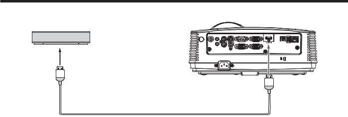
Connection (for video equipment having an HDMI terminal)
Equipment having an
HDMI terminal
To HDMI terminal
AUDIO |
AUDIO IN-3L |
S-VIDEO |
SERIAL |
COMPUTER / COMPONENT VIDEO |
USB-A |
LAN |
IN-1 |
|
|
|
USB-B |
||
|
|
|
|
IN-1 |
|
|
AUDIO OUT
AUDIO |
|
|
|
IN-2 |
AUDIO IN-3R |
|
IN-2 |
|
VIDEO |
MONITOR OUT |
|
|
AC IN |
|
|
 HDMI
HDMI
HDMI (with HDMI logo) cable (option)
Important:
t 6TF B DPNNFSDJBMMZ BWBJMBCMF )%.* XJUI )%.* MPHP DBCMF
t :PV EPO U IBWF UP DPOOFDU BOZ DBCMF GPS BVEJP JOQVU :PV DBO JOQVU WJEFP BOE BVEJP VTJOH BO )%.* DBCMF POMZ
t 8IFO )%.* BVEJP JTO U PVUQVU JU NBZ CF PVUQVU CZ UVSOJOH PGG UIF QPXFS PG UIF WJEFP FRVJQNFOU XJUI UIF QSPKFDUPS and the video equipment connected to each other and then turning back on the power.
t 4PNF DBCMFT NBZ OPU CF DPOOFDUFE DPSSFDUMZ EFQFOEJOH PO UIF TJ[F BOE TIBQF PG UIFJS DPOOFDUPST
When you connect this projector and a Digital device (such as a DVD player) via the HDMI terminal, black color may appear dark and deep, depending on the type of the connected device.
t 5IJT EFQFOET PO UIF CMBDL MFWFM TFUUJOH PG UIF DPOOFDUFE EFWJDF 5IFSF BSF UXP LJOET PG NFUIPET UP EJHJUBMMZ transfer image data, in which different black level settings are employed respectively. Therefore, the specifications of the signals output from DVD players differ, depending on the type of the digital data transfer method they use.
t 4PNF %7% QMBZFST BSF QSPWJEFE XJUI B GVODUJPO UP TXJUDI UIF NFUIPET UP PVUQVU EJHJUBM TJHOBMT 8IFO ZPVS %7% player is provided with such function, set it as follows.
EXPAND or ENHANCED NORMAL
t 4FF UIF VTFST HVJEF PG ZPVS %7% QMBZFS GPS EFUBJMT
t 4FU *OQVU -FWFM JO UIF 1JDUVSF NFOV EFQFOEJOH PO UIF EFWJDF UP CF VTFE
EN-13
Basic connections (continued)
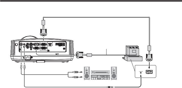
Projector + Computer
For computer with Mini D-SUB
Computer cable
COMPUTER IN
AUDIO OUT |
AUDIO AUDIO IN-3L S-VIDEO SERIAL |
COMPUTER / COMPONENT VIDEO |
USB-B USB-A LAN |
Computer |
|
|
IN-1 |
|
|
Necessary when outputting to both |
|
|
|
|
IN-1 |
|
|
|
|
|
a PC monitor and the projector. |
|
|
AUDIO |
|
|
|
||
IN-2 |
AUDIO IN-3R |
|
IN-2 |
|
|
|
VIDEO |
MONITOR OUT |
|
|
|
|
AC IN |
|
|
|
|
|
|
|
|
Computer cable (option) |
To monitor port |
MONITOR OUT
AUDIO 
 AUDIO IN-1
OUT 
 or IN-2
Audio cable (option)
PC audio cable (option) |
To PC audio output |
For analog connection:
1.Connect one end of the supplied computer cable to the COMPUTER IN terminal (1, 2) of the projector.
2.Connect the other end of the computer cable to the monitor port of the computer.
For monitor connection:
Connect the computer cable from the monitor to the MONITOR OUT terminal of the projector.
t *NBHFT NBZ OPU CF EJTQMBZFE DPSSFDUMZ EFQFOEJOH PO UIF UZQF PG UIF JOQVU TJHOBM 4FF UIF JOTUSVDUJPO NBOVBM PG the monitor.
t 4JHOBMT BSF DPNJOH GSPN UIF $0.165&3 */ UFSNJOBM PG UIF QSPKFDUPS
t 8IFO UIF 4UBOECZ .PEF JO UIF *OTUBMMBUJPO NFOV JT TFU UP .POJUPS 0VU UIF .0/*503 065 UFSNJOBM PVUQVUT signals during standby mode.
Important:
t 8IFO ZPV VTF B MPOHFS DPNQVUFS DBCMF JOTUFBE PG UIF QSPWJEFE DBCMF UIF JNBHF NBZ OPU CF QSPKFDUFE DPSSFDUMZ t 4PNF DPNQVUFST SFRVJSF BEEJUJPOBM DPOOFDUPST PS BOBMPH 3(# PVUQVU BEBQUFST UP CF DPOOFDUFE XJUI UIJT
projector. Contact your dealer for further information.
t 5IJT QSPKFDUPS VTFT TUFSFP NJOJ KBDL GPS JUT BVEJP JOQVU $IFDL UIF UZQF PG UIF BVEJP PVUQVU UFSNJOBM PG UIF connected computer and prepare a proper cable for connection. Some computers don’t have the audio output terminal.
t 4QFBLFS PVUQVU JT NPOP
t 8IFO UIF BVEJP DBCMF JT DPOOFDUFE UP UIF "6%*0 065 UFSNJOBM UIF TQFBLFS PVUQVU JT NVUFE
For Macintosh
t *G ZPVS .BDJOUPTI IBT OP WJEFP QPSU B NPOJUPS PVUQVU BEBQUFS JT SFRVJSFE $POUBDU ZPVS EFBMFS GPS GVSUIFS information.
t 4PNF .BDJOUPTIFT SFRVJSF B ."$ BEBQUFS GPS UIF DPNQVUFS DBCMF GPS DPOOFDUJPO XJUI UIJT QSPKFDUPS $POUBDU ZPVS dealer for further information.
About DDC
The COMPUTER/COMPONENT VIDEO IN-1 terminal of this projector complies with the DDC 1/2B standard. When a computer supporting this standard is connected to this terminal, the computer will automatically load the information from this projector and prepare for output of appropriate images.
t "GUFS DPOOFDUJOH B DPNQVUFS TVQQPSUJOH UIJT TUBOEBSE UP UIJT UFSNJOBM QMVH UIF QPXFS DPSE PG UIF QSPKFDUPS JO UIF wall outlet first, and then boot up the computer.
EN-14
Preparation
Preparation for projection
1.Attach the provided power cord to the projector.
2.Plug the power cord in the wall outlet.
3.Remove the lens cap.
Warning:
t Do not look into the lens directly when the projector is on. t The lens cap is for protecting the lens. If you leave
the lens cap on the lens with the projector turned on, it may be deformed because of heat build-up. Remove the lens cap when you turn on the projector.
t 0OF PG QPXFS DPSET GPS UIF 6 4 &VSPQF 6 , BOE
Korea is provided appropriately.
t This projector uses the power plug of three-pin grounding type. Do not remove the grounding pin from the power plug. If the power plug doesn’t fit your wall outlet, ask an electrician to change the wall outlet.
t *O DBTF UIBU UIF QPXFS DPSE GPS UIF 6 4 JT QSPWJEFE with this projector, never connect this cord to any outlet or power supply using other voltages or frequencies than rated. If you want to use a power supply using other voltage than rated, prepare an appropriate power cord separately.
t 6TF 7 "$ )[ UP QSFWFOU mSF PS electric shock.
t Do not place any objects on the power cord or do not place the projector near heat sources to prevent damage to the power cord. If the power cord should be damaged, contact your dealer for replacement because it may cause fire or electric shock.
t Do not modify or alter the power cord. If the power cord is modified or altered, it may cause fire or electric shock.
Caution:
t 1MVH JO UIF QPXFS DPSE mSNMZ 8IFO VOQMVHHJOH hold and pull the power plug, not the power cord.
t %P OPU QMVH JO PS PVU UIF QPXFS DPSE XJUI ZPVS hand wet. It may cause electric shock.
Important:
t 8IFO 4UBOECZ .PEF JO UIF *OTUBMMBUJPO NFOV JT set to LAN, Speaker Out, or Monitor Out, the fans rotate at very low speed during standby after plugging the power cord (with 5 second high speed rotation at the beginning) and after turning off the lamp. This is to cool down the projector operating various functions during standby and is not a malfunction. (When Standby Mode is set to Low, the fans stop during standby.)
Adjustment of the projection angle
For the best projection, project images on a flat screen installed at 90 degrees to the floor. If necessary, tilt the projector using the two adjustment feet on the bottom of the projector.
Using the adjustment feet (front)
1.Tilt up the projector to the appropriate angle.
2.Rotate the adjustment feet (front) for fine adjustment.
EN-15
Important:
t *OTUBMM UIF TDSFFO PO B nBU XBMM BU EFHSFFT UP UIF
floor.
t 4MBOUJOH UIF QSPKFDUPS NPSF UIBO ¡ SJHIU BOE MFGU PS ¡ GSPOU BOE SFBS NBZ DBVTF USPVCMF PS explosion of the lamp. You can tilt the projector up to 8 degrees using the adjustment feet only.
t *NBHFT NBZ OPU CF QSPKFDUFE JO B TIBQF PG B regular rectangle or with its aspect ratio 4:3, depending on the installation conditions of the projector and the screen.
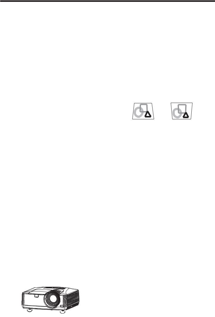
t 8IFO "VUP ,FZTUPOF JO UIF *OTUBMMBUJPO NFOV JT TFU to On, this projector automatically corrects vertical keystone distortion. For fine adjustment, press the KEYSTONE button on the projector or the remote control to display Keystone, and adjust the image by pressing the , button (or VOLUME , button on the remote control).
In the following cases:
Press the button. Press the button.
t 5IF BVUPNBUJD LFZTUPOF BEKVTUNFOU NBZ OPU be carried out correctly because of the ambient temperature and the installation conditions of the
projector and the screen. In such cases, correct the keystone manually.
t 8IFO UIF QSPKFDUPS JT QSPKFDUJOH JNBHFT XIFSF acceleration is present, such as in a vehicle and aircraft, the automatic keystone adjustment may not function correctly. In such a case, set Auto Keystone in the Installation menu to Off and correct the keystone manually.
t :PV DBO DPSSFDU UIF WFSUJDBM LFZTUPOFT )PXFWFS their adjustment ranges are limited in such correction.
Important:
t 8IFO UIF LFZTUPOF BEKVTUNFOU JT DBSSJFE PVU UIF adjustment value is indicated. Note that this value doesn’t mean a projection angle.
t 5IF BMMPXBCMF SBOHF PG UIF BEKVTUNFOU WBMVF JO the keystone adjustment varies depending on the installation condition, input signal and aspect settings in MENU.
t 8IFO UIF LFZTUPOF BEKVTUNFOU UBLFT FGGFDU UIF resolution decreases. In addition, stripes may appear or straight lines may bend in images with complicated patterns. They are not due to product malfunctions.
t /PJTF NBZ BQQFBS PO UIF TDSFFO EVSJOH UIF keystone adjustment because of the type of the video signal being projected and the setting values of the keystone adjustment. In such cases, set the keystone adjustment values in the range where the image is displayed without noise.
t 8IFO UIF LFZTUPOF BEKVTUNFOU JT DBSSJFE PVU UIF image may not be displayed correctly because of the type of input signal.
Basic operation
|
|
|
ON |
STANDBY |
|
|
4 |
FOCUS |
3 |
|
|
|
MAGNIFY |
|
ASPECT |
||
|
|
|
|
||
|
|
|
|
UP |
|
|
6 |
ZOOM |
VOL |
|
|
|
KEYSTONE |
DOWN |
3D |
||
|
|
|
|
||
|
|
|
|
|
AUTO |
|
|
|
MENU |
|
POSITION |
|
|
|
ENTER |
|
|
|
|
|
AV |
|
|
|
|
|
MUTE |
|
FREEZE |
|
|
|
VIEWER |
|
VIDEO |
|
|
|
1 |
|
|
|
|
|
COMPUTER |
|
|
|
|
|
UNPLUG |
|
S-VIDEO |
|
|
|
2 |
|
|
5 |
3, 1, 2 |
USB DISP. LAN DISP. |
DVI |
HDMI |
|
|
|
|
|||
1, 2
5
Power-on
1.Turn on the device connected to the projector first.
2.Plug the power cord in the wall outlet. t 5IF 108&3 JOEJDBUPS MJHIUT VQ
t *G UIF QPXFS DPSE JT VOQMVHHFE GSPN UIF XBMM outlet before the projector is cooled down completely after use, the fans may start rotating when the power cord is plugged in next time and the POWER button may not function. In this case, wait for the fans to stop and press the POWER button to light the indicator.
3.Press the POWER button on the control panel or the ON button on the remote control.
t *U NBZ UBLF BCPVU POF NJOVUF GPS UIF MBNQ UP light up.
t 5IF MBNQ PDDBTJPOBMMZ GBJMT UP MJHIU VQ 8BJU B few minutes and try to light the lamp again.
t "GUFS UIF 108&3 CVUUPO JT QSFTTFE UIF JNBHF may flicker before the lamp becomes stable. This is not a product malfunction.
t 3FHBSEMFTT PG UIF TFUUJOH PG -BNQ .PEF JO UIF
Installation menu, the Standard lamp mode is activated by default whenever the projector is turned on. The Lamp Mode is set to either
Standard or Low depending on the setting last selected, and you cannot switch the Lamp Mode in about one minute after the lamp is on.
Indicator |
STATUS |
POWER |
|
Condition |
|||
|
|
||
Stand-by |
- |
Red |
|
When the lamp is on. |
Green |
Green |
Important:
t *G UIF MBNQ FYDFQUJPOBMMZ UVSOFE PGG EVF UP UIF power interruption or voltage drop, it can happen that the lamp does not turn on even if you switch again the power supply on. In that case, please pull the electric cord out of the consent and put it again in the consent about 10 minutes later.
t %P OPU DPWFS UIF MFOT XJUI UIF MFOT DBQ XIJMF UIF lamp is on.
t 5IF QSPKFDUPS TUBSUT XBSNJOH VQ XIFO UIF 108&3 button is pressed. During the warm-up process, images may appear dark and no commands are accepted.
t #Z CMJOLJOH SFE UIF 45"564 JOEJDBUPS JOEJDBUFT UIBU the lamp should be replaced soon. Replace the lamp when the STATUS indicator blinks red. (See page 52 and 56.)
t *NBHFT NBZ OPU CF QSPKFDUFE XJUI HPPE RVBMJUZ JO an extremely hot or cold environment. (This is not a product malfunction.)
t *O PSEFS UP FOTVSF UIF TBGFUZ JO DBTF PG USPVCMF XJUI the projector, use an electrical outlet having an earth leakage breaker to supply the power to the projector. If you do not have such outlet, ask your dealer to install it.
4.Adjust the focus by turning the focus ring.
5.Choose your desired external input source using the COMPUTER, HDMI, LAN DISP., USB DISP., VIEWER, VIDEO, or S-VIDEO button.
t 5IF JOQVU TPVSDF JT TXJUDIFE CFUXFFO
Computer1, Computer2, HDMI, LAN Display, USB Display, and PC Less Presentation at every press of the COMPUTER button on the control panel.
t 5IF JOQVU TPVSDF JT TXJUDIFE CFUXFFO 7JEFP BOE
S-Video at every press of the VIDEO button on the control panel.
t 8IFO QSFTTJOH UIF $0.165&3 PS )%.*
LAN DISP., USB DISP., VIEWER, VIDEO, or S-VIDEO button on the remote control, the input source switches directly as the button pressed.
t :PV DBOOPU DIBOHF UIF JOQVU TPVSDF XIJMF UIF menu is being displayed.
t 8IFO $PNQVUFS JT DIPTFO BT UIF TPVSDF
images supplied from the computer may flicker. Press the or button on the remote control to reduce flicker, if it occurs.
EN-16

Basic operation (continued)
t 5P BWPJE QFSNBOFOUMZ JNQSJOUJOH B mYFE JNBHF onto your projector, please do not display the same stationary images for long period.
6.Adjust the image size by turning the zoom ring. t *G OFDFTTBSZ BEKVTU UIF GPDVT BOE [PPN BHBJO
When fine streaks are seen on projected images
This is due to interference with the screen surface and is not a malfunction. Replace the screen or displace the focus a little.
Power-off
Use the following procedure to turn off the projector. The lamp may deteriorate if the projector is powered off and on repeatedly within 30 minutes after the lamp is lighted.
1.Press the POWER button on the control panel or the STANDBY button on the remote control.
t 5IF NFTTBHF i1PXFS 0GG 1SFTT again” appears on the screen.
t 5P DBODFM QSFTT BOZ CVUUPO FYDFQU UIF 108&3 button.
(Some buttons on the remote control don’t function for cancel.)
2.Press the POWER button on the control panel or the STANDBY button on the remote control within 10 seconds again.
t 5IF MBNQ XJMM HP PVU BOE UIF 45"564 JOEJDBUPS will start blinking.
3.Wait about 90 seconds for the STATUS indicator to be turned off.
Direct Power OFF
You can turn off this projector just by unplugging the power cord without pressing the POWER button.
t %PO U TIVU EPXO UIF QSPKFDUPS XIJMF UIF 45"564 indicator is blinking after the lamp lights up because the lamp’s life may be shortened.
t %PO U UVSO UIF QSPKFDUPS CBDL PO SJHIU BGUFS TIVUUJOH it down because the lamp’s life may be shortened. (Wait about 10 minutes before turning the projector back on.)
t #FGPSF TIVUUJOH EPXO UIF QSPKFDUPS CF TVSF UP DMPTF the menu screen. If you shut down the projector without closing the menu, the setting data of the menu may not be saved.
t *G ZPV TIVU EPXO UIF QSPKFDUPS XIJMF DPOUSPMMJOH the projector using the network function, the application software such as ProjectorView may fail. For details, see “User Manual of LAN Control Utility” contained in the CD-ROM.
AUTO POSITION button
When the image isn’t projected in the right position with Computer selected as the input source, follow the procedure below.
1.Project a bright image such as the “Recycle Bin” window on the full screen.
2.If the screen saver is running, turn it off.
3.Press the AUTO POSITION button.
t *G UIF JNBHF JT TUJMM OPU JO UIF SJHIU QPTJUJPO adjust the image position using the Signal menu. See page 24.
4.Unplug the power cord.
t 5IF 108&3 JOEJDBUPS XJMM HP PVU
t *G UIF QPXFS DPSE TIPVME CF VOQMVHHFE accidentally while either the STATUS indicator is blinking or the lamp is on, allow the projector to cool down for 10 minutes with the power off. To light the lamp again, press the POWER button (or ON button). If the lamp doesn’t light up immediately, repeat pressing the POWER button (or ON button) two or three times. If it should still fail to light up, replace the lamp.
Important:
t 8IFO TUPSJOH UIF QSPKFDUPS JO UIF DBSSZJOH DBTF UIF lens should face up.
Before carrying the projector, rotate the focus ring and zoom ring to adjust the lens to the shortest. This prevents the possible damages of the lens.
Volume from the speaker
Press the VOLUME or button to change the volume from the speaker.
The volume control bar will appear on the screen.
|
|
|
Volume |
|
|
|
|
|
|
|
|
|
|
|
16 |
|
|
|
|
|
|
|
|
|
|
|
|
|
|
|
|
|
|
|
|
t 5IF WPMVNF DPOUSPM CBS XJMM EJTBQQFBS BCPVU seconds after the VOLUME button is released. t 5IF 70-6.& CVUUPOT EPO U GVODUJPO XIJMF UIF
menu is being displayed.
t 8IFO B IJHI MFWFM BVEJP TJHOBM TVDI BT B %7% audio signal, is supplied to the AUDIO IN terminal, the output from the speaker may be distorted.
You can change the volume also by using the Volume setting in the Audio menu.
(See page 21 for menu setting.)
1.Display the Audio menu.
2.Select Volume by pressing the or button.
3.Adjust the volume by pressing the or button.
4.Press the MENU button to exit the menu.
AV mute
The video and audio signals are temporarily muted when the AV MUTE button is pressed. To cancel muting, press the AV MUTE button again.
EN-17
Basic operation (continued)
Setting the aspect ratio
You can change the aspect ratio of the input video signal (or the ratio of width to height of the image). Change the setting according to the type of the input video signal.
With the remote control:
1.Press the ASPECT button.
t &WFSZ UJNF UIF "41&$5 CVUUPO JT QSFTTFE UIF aspect mode changes from Normal to 16:9, to Full, and back to Normal.
With the Picture menu:
(See page 21 for menu setting.)
1.Display the Picture menu.
2.Select Aspect Ratio by pressing the or button.
Aspect Ratio |
Normal |
|
|
3.Select your desired aspect ratio by pressing the or button.
When 16:9 
 is selected. (For XD550U and XD560U only)
4.Press the ENTER button.
5.Select your desired position (Center, Upper or Lower) by pressing the or button.
To cancel the menu:
6. Press the MENU button.
Important:
t 8IFO B JNBHF JT LFQU EJTQMBZFE GPS B MPOH time before displaying 4:3 image, the afterimages of the black bars may appear on the 4:3 image screen. Consult your dealer in this case.
Caution:
t 5IF MBNQ DBO U CF MJU BHBJO GPS POF NJOVUF BGUFS turned off for safety purpose. It will take another one minute for the STATUS indicator to go out. If you want to turn on the projector again, wait until the indicator goes out, and then press the POWER button.
t 5IF BJS PVUMFU GBOT SPUBUF GBTUFS BT UIF UFNQFSBUVSF around the projector rises.
t 8IFO UIF UFNQFSBUVSF BSPVOE UIF QSPKFDUPS SJTFT high, the sign “Temperature!!” blinks red on the screen. If the temperature stays high, the lamp will go out automatically.
Important:
t %P OPU EJTQMBZ B TUJMM QJDUVSF GPS B MPOH UJNF because the afterimages may persist on the screen.
When connecting to a laptop computer:
When this projector is connected to a laptop computer, there may be times when images may not be projected. When it occurs, set the computer so that it can output signals externally. The procedure varies across computers in use. See the instruction manual of your computer.
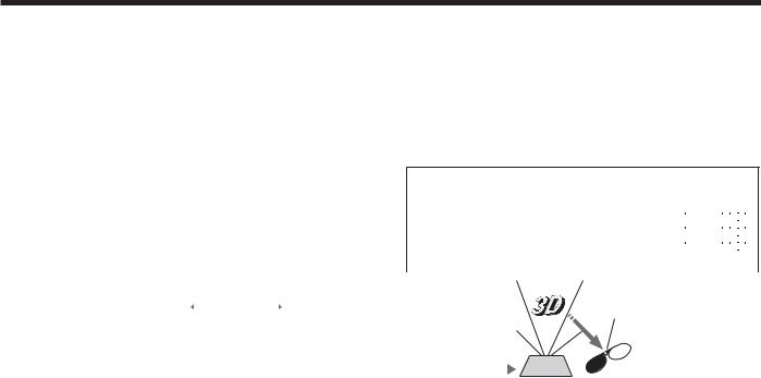
Watching 3D content
You can enjoy 3D content with this projector.
In order to watch 3D content, you need to have the following items:
t 'JFME TFRVFOUJBM % WJEFP DPOUFOUT t %-1 -JOL BDUJWF % HMBTTFT
(Field-sequential: The system which displays alternately the image for the left eye and the right eye.)
3D image Format
|
|
Page flipping |
|
Side by side |
|
Top & bottom |
|
Checkerboard |
||||||||||||||||||||||
(Field sequential) |
|
|
|
|
|
|
|
|
|
|
|
|
|
|
|
|
|
|
|
|||||||||||
|
|
|
|
|
|
|
|
|
|
|
|
|
|
|
|
|
|
|
|
|
|
|
|
|
|
|
|
|
|
|
|
L |
R |
|
|
|
|
|
|
|
|
|
|
|
|
|
|
|
|
L |
|
|
L |
R |
L |
R |
L |
R |
L |
R |
|
|
|
L |
|
|
|
|
|
|
|
|
|
|
|
|
|
|
|
R |
L |
R |
L |
R |
L |
R |
L |
|
||||
|
|
|
|
R |
|
|
|
|
|
L |
R |
|
|
|
|
|
|
L |
R |
L |
R |
L |
R |
L |
R |
|
||||
|
|
|
|
|
|
|
|
|
|
|
|
|
|
|
|
|
|
|
|
|
|
R |
L |
R |
L |
R |
L |
R |
L |
|
|
|
|
|
|
|
|
|
|
|
|
|
|
|
|
|
|
|
|
R |
|
|
L |
R |
L |
R |
L |
R |
L |
R |
|
|
|
|
|
|
|
|
|
|
|
|
|
|
|
|
|
|
|
|
|
|
|
R |
L |
R |
L |
R |
L |
R |
L |
|
|
|
|
|
|
|
|
|
|
|
|
|
|
|
|
|
|
|
|||||||||||||
|
|
Supported |
|
Not supported |
|
Not supported |
|
Not supported |
||||||||||||||||||||||
|
|
|
|
|
|
|
|
|
|
|
|
|
|
|
|
|
|
|
|
|
|
|
|
|
|
|
|
|
|
|
|
|
|
|
|
|
|
|
|
|
|
|
|
|
|
|
|
|
|
The shutter timing of the 3D |
|||||||||||
|
|
|
|
|
|
|
|
|
|
|
|
|
|
|
|
|
|
|
||||||||||||
|
|
|
|
|
|
|
|
|
|
|
|
|
|
|
|
|
|
|
||||||||||||
|
|
|
|
|
|
|
|
|
|
|
|
|
|
|
|
|
|
|
glasses is controlled by |
|||||||||||
|
|
|
|
|
|
|
|
|
|
|
|
|
|
|
|
|
|
|
Sensor being synchronized with |
|||||||||||
|
|
|
|
|
|
|
|
|
|
|
|
|
|
|
|
|
|
|
switching of right and left |
|||||||||||
|
|
|
|
|
|
|
|
|
|
|
|
|
|
|
|
|
|
|
3D image which is detected |
|||||||||||
|
|
|
|
|
|
|
|
|
|
|
|
|
|
|
|
|
|
|
by the sensor of glasses. |
|||||||||||
|
|
|
|
|
|
|
|
|
|
|
|
|
|
|
|
|
|
|
R |
|
|
|
|
|
|
|
|
|
||
|
|
|
|
|
|
L |
R |
L |
R |
|
|
|
|
L |
|
|
|
|
|
|
|
|
|
|||||||
|
|
|
|
|
|
|
|
|
|
|
|
|
|
|
|
|
|
|
|
|
|
|
|
|
|
|
||||
|
|
|
|
DLP™ Projector |
|
|
|
|
DLP™ Link™ active |
|
|
|
|
|
|
|
|
|
||||||||||||
|
|
|
|
|
|
|
|
|
|
|
|
|
|
|
|
|
||||||||||||||
|
|
|
|
|
|
|
|
3D glasses |
|
|
|
|
|
|
|
|
|
|||||||||||||
|
|
|
|
|
|
|
|
|
|
|
|
|
|
|
|
|
|
|
|
|
|
|
|
|
|
|
||||
Play the field-sequential 3D video contents on a computer or DVD player, and then, connect the cable with the projector.
Go to the Picture menu and set the 3D option to On. (See page 22.)
Put on the 3D glasses to watch the contents.
If the contents are not projected correctly, go to the Picture menu, and switch the 3D Sync Invert option to On.
Important:
t :PV DBOOPU QSPKFDU UIF % DPOUFOU GSPN UIF JOQVU source LAN Display, USB Display, and PC Less Presentation.
t *G UIF WJFXJOH EJTUBODF JT OFBSFS UIBO UIF recommended distance, it will cause physical discomfort and eye fatigue.
t 8BUDI UIF DPOUFOUT JO GSPOU PG UIF TDSFFO OPU BU CJH angle. If you are viewing the screen at big angle, you may not be able to view 3D contents correctly.
t *G ZPV BSF OPU WJFXJOH % DPOUFOUT DPSSFDUMZ check to see if the 3D glasses are powered on or adequately charged. See the instruction manual of the 3D glasses for more information.
t 5IFSF BSF QFSTPOBM EJGGFSFODFT JO WJFXJOH UIF % images. For persons with myopia, hypermetropia, astigmatism or left and right sights, please wear glasses to correct them then wear the 3D glasses.
t 5IF QJDUVSF TFFNT NJTQMBDFE BU UIF TUBSU PG projecting the 3D images, however, this is not a malfunction.
t 8JUI UIF % PQUJPO TFU UP 0O DPOUFOUT EJTQMBZFE on the projector appear darker. It is normal and does not mean the projector is malfunctioning.
EN-18
 Loading...