


 Loading...
Mitsubishi WD-60738, WD-65738, WD-65838, WD-73738, WD-73838 User Guide
...3D DLP ™ HOME-CINEMA TELEVISION
MODELS
738 Series
838 Series
OWNER’S GUIDE
•For questions:
-- Visit our website at www.mitsubishi-tv.com. -- E-mail us at MDEAservice@mdea.com.
-- Call Consumer Relations at 800-332-2119.
•For information on System Reset, please see the back cover.
•To order replacement or additional remote controls or lamp cartridges, visit our website at www.mitsuparts.com or call 800-553-7278.
•838 Series. IR emitter cables for NetCommand home-theater control are available for purchase from Mitsubishi. Call 800-553-7278 and request either part number 242D483020 (two-ended cable) or part number 299P254020 (four-ended cable).
®

CAUTION
RISK OF ELECTRIC SHOCK
DO NOT OPEN
CAUTION: TO REDUCE THE RISK OF ELECTRIC SHOCK, DO NOT REMOVE COVER (OR BACK). NO USER SERVICEABLE PARTS INSIDE. REFER SERVICING TO QUALIFIED SERVICE PERSONNEL.
The lightning flash with arrowhead symbol within an equilateral triangle is intended to alert the user of the presence of uninsulated “dangerous voltage” within the product’s
enclosure that may be of sufficient magnitude to constitute a risk of electric shock to persons.
The exclamation point within an equilateral triangle is intended to alert the user to the presence of important operating and maintenance (servicing) instructions in the literature accompanying the product.
MAINS DISCONNECTION: The mains plug is used as the disconnect device. The mains plug shall remain readily operable.
Stand Requirement
CAUTION: Use these Mitsubishi TV models only with the Mitsubishi stand models shown here. Other stands can result in instability and possibly cause injury.
TV Model |
Stand Model |
|
|
|
|
WD-60738, WD-65738 |
MB-S60/65A |
|
WD-65838 |
||
|
||
|
|
|
WD-73738 |
MB-S73A |
|
WD-73838 |
||
|
||
|
|
82-inch TVs. Mitsubishi does not design, manufacture, or sell matching bases for 82-inch televisions (WD-82738, WD-82838). When selecting a stand, base, or other furniture to support the TV, please make sure it is designed with the appropriate dimensions for stability and to support the TV’s total weight as well as the weight of any additional equipment you plan to store.
TV WEIGHT: This TV is heavy. Exercise extreme care when lifting or moving it. Lift or move the TV with a minimum of two adults. To prevent damage to the TV, avoid jarring or moving it while it is turned on. Always power off your TV, unplug the power cord, and disconnect all cables before moving it.
WARNING: To reduce the risk of fire or electric shock, do not expose this apparatus to rain or moisture.
WARNING: This product contains chemicals known to the State of California to cause cancer and/or birth defects or other reproductive harm.
For assistance call 1(800) 332-2119
FCC Declaration of Conformity
Product: |
Projection Television Receiver |
Models: |
WD-60738, WD-65738, WD-73738, |
|
WD-82738 |
|
WD-65838, WD-73838, WD-82838 |
Responsible |
Mitsubishi Digital Electronics |
Party: |
America, Inc. |
|
9351 Jeronimo Road |
|
Irvine, CA 92618-1904 |
Telephone: |
(800) 332-2119 |
This device complies with Part 15 of the FCC Rules. Operation is subject to the following two conditions:
(1)This device may not cause harmful interference, and
(2)This device must accept any interference received, including interference that may cause undesired operation.
Note: This equipment has been tested and found to comply with the limits for a Class B digital device, pursuant to part 15 of the FCC Rules. These limits are designed to provide reasonable protection against harmful interference in a residential installation. This equipment generates, uses and can radiate radio frequency energy and, if not installed and used in accordance with the instructions, may cause harmful interference to radio communications. However, there is no guarantee that interference will not occur in a particular installation. If this equipment does cause harmful interference to radio or television reception, which can be determined by turning the equipment off and on, the user is encouraged to try to correct the interference by one or more of the following measures:
-- Reorient or relocate the receiving antenna.
-- Increase the separation between the equipment and the receiver.
-- Connect the equipment into an outlet on a circuit different from that to which the receiver is connected.
-- Consult the dealer or an experienced radio/ TV technician for help.
Changes or modifications not expressly approved by Mitsubishi could cause harmful interference and would void the user’s authority to operate this equipment.
Note: Features and specifications described in this owner’s guide are subject to change without notice.

Contents |
|
|
Important Information About Your TV |
|
|
|
Installation and Operating Notes. . . . . . . . . . . . . . |
4 |
|
Important Safety Instructions. . . . . . . . . . . . . . . . |
5 |
1 |
Basic Setup and Operation |
|
|
Package Contents. . . . . . . . . . . . . . . . . . . . . . . . |
7 |
|
Before You Begin.. . . . . . . . . . . . . . . . . . . . . . . . |
8 |
|
First-Time Power-On.. . . . . . . . . . . . . . . . . . . . . . |
8 |
|
TV Controls.. . . . . . . . . . . . . . . . . . . . . . . . . . . . |
9 |
|
Remote Control. . . . . . . . . . . . . . . . . . . . . . . |
9 |
|
The TOOLS Key and Menu. . . . . . . . . . . . . . |
10 |
|
TV Control Panel. . . . . . . . . . . . . . . . . . . . . |
11 |
|
The STATUS Indicator.. . . . . . . . . . . . . . . . . |
11 |
|
Setting Up TV Inputs. . . . . . . . . . . . . . . . . . . . . |
12 |
|
Basic TV Operation. . . . . . . . . . . . . . . . . . . . . . |
14 |
|
Using the TV with a Personal Computer. . . . . . . . |
17 |
2 |
TV Connections |
|
|
Before You Begin.. . . . . . . . . . . . . . . . . . . . . . . |
19 |
|
Connection Types and Audio/Video Quality .. . . . |
19 |
|
Inputs and Outputs. . . . . . . . . . . . . . . . . . . . . . |
20 |
|
HDMI Device.. . . . . . . . . . . . . . . . . . . . . . . . . . . . |
22 |
|
Y Pb Pr Component Video Device. . . . . . . . . . . . |
23 |
|
DVI Video Device. . . . . . . . . . . . . . . . . . . . . . . . |
23 |
|
Antenna or Cable TV Service.. . . . . . . . . . . . . . . |
24 |
|
Composite Video Device.. . . . . . . . . . . . . . . . . . |
24 |
|
VCR or DVD Recorder to an Antenna or |
|
|
Wall Outlet Cable. . . . . . . . . . . . . . . . . . . . . . . |
24 |
|
A/V Receiver. . . . . . . . . . . . . . . . . . . . . . . . . . . |
25 |
|
A/V Receiver with HDMI Output.. . . . . . . . . . . . . |
25 |
|
Supplemental Audio Connections. . . . . . . . . . . . |
26 |
3 |
TV Features |
|
|
Sleep Timer.. . . . . . . . . . . . . . . . . . . . . . . . . . . |
28 |
|
FAV (Favorite Channels). . . . . . . . . . . . . . . . . . . |
28 |
|
ChannelView Channel Listings.. . . . . . . . . . . . . . |
29 |
|
Status Display. . . . . . . . . . . . . . . . . . . . . . . . . . |
30 |
|
Using an External Sound System.. . . . . . . . . . . . |
31 |
|
Picture Shape and Display Formats. . . . . . . . . . . |
32 |
|
3D Video.. . . . . . . . . . . . . . . . . . . . . . . . . . . . . |
33 |
|
Camera Images and Music Files. . . . . . . . . . . . . |
35 |
|
USB Source Devices (838 Series).. . . . . . . . . |
35 |
|
Photos and Motion Video as |
|
|
Composite Video. . . . . . . . . . . . . . . . . . . . |
37 |
|
Using an Audio-Only Device. . . . . . . . . . . . . |
37 |
|
Wireless Audio Playback.. . . . . . . . . . . . . . . |
38 |
|
Sound Projector (838 Series).. . . . . . . . . . . . . . . |
39 |
|
StreamTV™ Internet Media.. . . . . . . . . . . . . . . . |
43 |
|
Introduction to Home-Theater Control. . . . . . . . . |
46 |
4 TV Menus |
|
Main Menu. . . . . . . . . . . . . . . . . . . . . . . . . . . . |
47 |
Picture. . . . . . . . . . . . . . . . . . . . . . . . . . . . . . . |
47 |
Sound.. . . . . . . . . . . . . . . . . . . . . . . . . . . . . . . |
51 |
Captions. . . . . . . . . . . . . . . . . . . . . . . . . . . . . . |
53 |
Setup. . . . . . . . . . . . . . . . . . . . . . . . . . . . . . . . |
54 |
Inputs. . . . . . . . . . . . . . . . . . . . . . . . . . . . . . . . |
57 |
Lock.. . . . . . . . . . . . . . . . . . . . . . . . . . . . . . . . |
59 |
5 NetCommand IR Control |
|
About NetCommand IR Control.. . . . . . . . . . . . . |
62 |
IR Emitters. . . . . . . . . . . . . . . . . . . . . . . . . . . . |
63 |
NetCommand Setup.. . . . . . . . . . . . . . . . . . . . . |
64 |
Operating NetCommand-Controlled Devices. . . . |
65 |
6NetCommand IR Control of an A/V Receiver
Controlling an A/V Receiver after NetCommand
Setup. . . . . . . . . . . . . . . . . . . . . . . . . . . . . . . 68
Setting Up A/V Receiver Control
Power and Volume. . . . . . . . . . . . . . . . . . . . 69
Automatic Audio/Video Switching Over an HDMI
Connection. . . . . . . . . . . . . . . . . . . . . . . . 70
Appendices
Appendix A: Programming the Remote Control. . 75
Appendix B: Bypassing the Parental Lock. . . . . . 81
Appendix C: HDMI Control of CEC Devices. . . . . 83
Appendix D: TV Care
Lamp-Cartridge Replacement.. . . . . . . . . . . 86
Cleaning Recommendations. . . . . . . . . . . . . 88
Care of the Remote Control.. . . . . . . . . . . . . 88
Appendix E: Troubleshooting. . . . . . . . . . . . . . . 89
Trademark and License Information. . . . . . . . . . . 96
Network Service Disclaimer. . . . . . . . . . . . . . . . . 96
Warranty. . . . . . . . . . . . . . . . . . . . . . . . . . . . . . 103
Index. . . . . . . . . . . . . . . . . . . . . . . . . . . . . . . . . 105
For assistance call 1(800) 332-2119

4
For Your Records
Record the model number, serial number, and purchase date of your TV. The model and serial numbers are on the back of the TV. Refer to this page when requesting assistance with the TV.
MODEL NUMBER
SERIAL NUMBER
TV
Internal Fans
cooling fans maintain proper operating temperatures inside the TV. It is normal to hear the fans
you first turn on the TV, during quiet scenes viewing the TV, and for a short time after shutting
the TV. You may notice louder fan noise about 30 after shutting off the TV and while using the
Lamp Energy setting.
PURCHASE DATE
RETAILER NAME
LOCATION
Custom cabinet installation must allow for proper air circulation around the television.
NOTE TO CATV SYSTEM INSTALLER: THIS REMINDER IS PROVIDED TO CALL THE CATV SYSTEM INSTALLER’S ATTENTION TO ARTICLE 820-40 OF THE NEC THAT PROVIDES GUIDELINES FOR THE PROPER GROUNDING AND, IN PARTICULAR, SPECIFIES THAT THE CABLE GROUND SHALL BE CONNECTED TO THE GROUNDING SYSTEM OF
THE BUILDING, AS CLOSE TO THE POINT OF CABLE ENTRY AS PRACTICAL.
Replacement
lamp-replacement instructions, see Appendix D.
Order a Replacement Lamp Under Warranty
(800) 553-7278. Please have model number, serial and TV purchase date available.
To Purchase a Replacement Lamp After Warranty
Visit our website at www.mitsuparts.com or call (800) 553-7278. Order new lamp part number 915B441001.
Children and TV Viewing
The American Academy of Pediatrics discourages television viewing for children younger than two years of age.
TV Software
Do not attempt to update the software of this TV with software or USB drives not provided by or authorized by Mitsubishi Digital Electronics America, Inc. Nonauthorized software may damage the TV and will not be covered by the warranty.
For assistance call 1(800) 332-2119

5
Important Safety Instructions |
|
|
Please read the following safeguards for your TV and |
E XAMP LE OF ANTE NNA GR OUNDING |
|
retain for future reference. Always follow all warnings |
||
|
||
and instructions marked on the television. |
|
1)Read these instructions.
2)Keep these instructions.
3)Heed all warnings.
4)Follow all instructions.
5)Do not use this apparatus near water.
6)Clean only with dry cloth.
7)Do not block any ventilation openings. Install in accordance with the manufacturer’s instructions.
8)Do not install near any heat sources such as radiators, heat registers, stoves, or other apparatus (including amplifiers) that produce heat.
9)Do not defeat the safety purpose of the polarized or grounding-type plug. A polarized plug has two blades with one wider than the other. A grounding type plug has two blades and a third grounding prong. The wide blade or the third prong are provided for your safety. If the provided plug does not fit into your outlet, consult an electrician for replacement of the obsolete outlet.
10)Protect the power cord from being walked on or pinched particularly at plugs, convenience
receptacles, and the point where they exit from the apparatus.
11)Only use attachments/accessories specified by the manufacturer.
12)Use only with the cart, stand, tripod, bracket, or table specified
by the manufacturer, or sold with the apparatus. When
a cart is used, use caution when moving the cart/apparatus combination to avoid injury from tip-over.
13)Unplug this apparatus
during lightning storms or when unused for long periods of time.
14)Refer all servicing to qualified service personnel. Servicing is required when the apparatus has been damaged in any way, such as power-supply cord or plug is damaged, liquid has been spilled or objects have fallen into the apparatus, the apparatus has been exposed to rain or moisture, does not operate normally, or has been dropped.
|
|
|
|
|
|
|
ANTE NNA |
|
|
|
|
|
|
|
|
|
|
|
|
|
|
|
LE AD IN WIR E |
GR OUND C LAMP |
|
|
|
||||
|
|
|
|
|
|
|
ANTE NNA |
|
|
|
|
|
|
|
DIS C HAR GE UNIT |
E LE C TR IC |
|
|
(NE C AR TIC LE 810-20) |
||||
|
|
|
|||||
S E R VIC E |
|
GR OUNDING |
|||||
E QUIP ME NT |
|
||||||
|
C ONDUC TOR S |
||||||
|
|
|
|
|
|
||
|
|
|
|
|
|
(NE C AR TIC LE 810-21) |
|
|
|
|
|
|
|
GR OUND C LAMP S |
|
|
|
|
|
|
|
||
|
|
|
|
|
|||
|
|
|
|
|
|
P OWE R S E R VIC E GR OUNDING |
|
|
|
|
|
|
|
E LE C TR ODE S YS TE M |
|
NE C — NATIONAL E LE C TR IC AL C ODE |
|
(NE C AR T 250, P AR T H) |
|||||
Outdoor Antenna Grounding
If an outside antenna or cable system is connected to the TV, be sure the antenna or cable system is grounded so as to provide some protection against voltage surges and built-up static charges.
Replacement Parts
When replacement parts are required, be sure the service technician has used replacement parts specified by the manufacturer or have the same characteristics as the original part. Unauthorized substitutions may result in fire, electric shock or other hazards.
For assistance call 1(800) 332-2119

6
Special Features of Your TV
Your new high-definition widescreen television has many special features that make it the perfect center of your home entertainment system, including:
1080p High-Definition DLP Display System
Your Mitsubishi HDTV uses Texas Instruments Digital Light Processing™ technology for rear-projection TVs to create the picture you see on screen. All images are displayed at 1080p. The TV uses Plush 1080p® 5G to convert lower-resolution signals to 1080p for display. The TV can also accept 1080p original signals and main-
tain them at 1080p through all processing until displayed.
3D Television
All Mitsubishi 738 and 838 1080p home-Cinema HDTV’s can display 3D content originating in several different formats. This feature lets you experience the new 3D technologies applied to many recent movies and video games. Immerse yourself in your favorite video game, movie, or sporting event displayed in 3D.
16:9 Widescreen Picture Format
Enjoy a full theatrical experience in the comfort of your home. View pictures as film directors intended them. Digital TV broadcasts, DVDs and newer video game consoles support this widescreen format.
Easy Connect Auto Input Sensing
Easy Connect™ Auto Input Sensing automatically recognizes when you plug in a device and prompts you to assign a name to it. The TV ignores any unused inputs, so the result is an uncluttered menu where you can easily select devices by name.
Home-Theater Control
HDMI Control
All models. HDMI devices with Consumer Electronics Control (CEC) capabilities may be compatible with the TV’s HDMI Control feature. Compatible devices can receive control signals through the HDMI connection, allowing the TV’s remote control to operate some functions of these devices.
NetCommand with IR Learning
838 Series. Your Mitsubishi HDTV offers a new level of networking that seamlessly integrates selected older A/V products with new and future digital products. NetCommand® supports IR (infrared) control of products such as DVD players, cable boxes, satellite receivers, and VCRs. The necessary IR emitter cables are available for purchase separately from Mitsubishi.
Immersive Sound Technology
Integrated HDTV Tuner
Your widescreen Mitsubishi HDTV has an internal HDTV tuner able to receive both over-the-air HDTV broadcasts (received via an antenna) and non-scrambled digital cable broadcasts, including non-scrambled HDTV cable programming.
High-Definition Video Inputs
•Component Video Inputs. Also called Y/Pb/Pr inputs, these inputs receive standard analog video formats of 480i, 480p, plus 720p and 1080i highdefinition signals. This provides a high level of flexibility when connecting DVD players/recorders, cable boxes, and satellite receivers.
•HDMI Inputs. HDMI® inputs provide additional high-performance, high-definition connections for maximum flexibility in your choice of home theater products. These inputs accept digital 480i, 480p,
720p, 1080i, and 1080p video signals plus PCM digital stereo signals. The HDMI inputs can also accept a variety of PC signals and resolutions.
These inputs support Deep Color (up to 36 bits) and the x.v.Color™ extended color gamut.
Used with an adapter, these HDMI inputs also accept compatible digital DVI video signals. The HDMI inputs are HDCP copy-protection compatible.
838 Series. Sound Projector technology uses the TV’s bank of speakers to create a simulated surround sound effect by reflecting sound off the room walls.
StreamTV Internet
StreamTV™ brings many popular internet applications to your TV. Among them is the VUDU™ movie service, offering the largest on-demand HD movie selection anywhere, featuring full 1080p and 5.1 surround sound. VUDU allows you to enjoy movies with no store visits, no mailing, no late fees and no subscriptions.
ENERGY STAR
The following TV models are ENERGY STAR® qualified: WD-65738, WD-73738, WD-82738 WD-65838, WD-73838, WD-82838
Products that earn the ENERGY STAR prevent greenhouse gas emissions by meeting strict energy efficiency guidelines set by the U.S. Environmental Protection Agency and the U.S. Department of Energy.
For assistance call 1(800) 332-2119
1 |
Basic Setup and Operation |
7 |
|
||
|
|
|
|
|
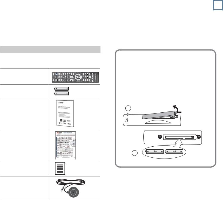
Package Contents
Please take a moment to review the following list of items to ensure that you have received everything.
Remote Control
Two AA Batteries |
AA |
|
AA |
Basic Owner’s Guide |
|
Quick Setup Guide
Product Registration
Card
838 Series. Calibration
Microphone
Installing the Remote Control
Batteries
1.Remove the remote control’s back cover by gently pressing in the tab and lifting off the cover.
2.Load the batteries, making sure the polarities
(+)and (-) are correct. For best results, insert the negative (-) end first.
3.Snap the cover back in place.
The remote control requires two AA alkaline batteries.
2
For assistance call 1(800) 332-2119
8 |
1. Basic Setup and Operation |
Before You Begin
1.Review the important safety, installation, and operating information at the beginning of this book.
2.Choose a location for your TV.
•Allow at least four inches of space on all sides of the TV to help prevent overheating. Overheating may cause premature failure of the TV as well as shortened lamp life.
•Avoid locations where light may reflect off the screen.
•See the stand requirements on page 2.
3.Install the batteries in the remote control.
4.Plug the TV into an AC power outlet.
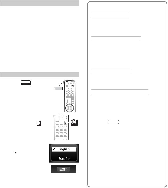
First- |
-On |
|
1. Press the TV |
key to |
TV |
ensure that the remote |
TV |
|
control is in TV mode. |
||
|
2. Aim the bulb end of the remote control at the TV and press the POWER key  . Wait for the Welcome screen.
3.If you wish to change the menu language to Español, press .
4.Press to highlight EXIT. Press ENTER to clear the menu.
For assistance call 1(800) 332-2119
TV Tips
Turning the TV On or Off
•Point the bulb end of the remote control at the front of the TV and press the POWER key.
•Press the POWER button on the TV control panel.
If You Turn Off the TV by Mistake
•Press POWER again, within about 60 seconds, to have the TV come back on immediately.
•If the STATUS indicator is flashing green, (about 60 seconds after you shut off power), wait a few moments for the indicator to stop flashing and press POWER to turn the TV on again.
Controlling Sound Volume
•Press VOL to adjust the sound level.
•See also “Controlling A/V Receiver Sound Volume” on page 31.
Changing Channels (antenna sources)
NOTE: Perform a channel scan to enable reception of digital channels. See Setup > Channel, page 55.
•Enter the channel number using the number keys on the remote control and press ENTER. For a two-part digital channel, such as 3-1,
—1 to include a dash (separator).
CANCELpress 3
•Press CH to change channels one channel at a time.
•Press and hold CH to move quickly through channels.
•Press LAST to return to the previously tuned channel.
•Press GUIDE to display ChannelView channel listings, highlight a channel, and press ENTER.
•Use the Fav (Favorites) feature to tune to up to nine favorite channels. See page 28.
•Use the CH key to tune to preselected groups of channels using ChannelView custom channel banks. See page 29.

1. Basic Setup and Operation |
9 |
TV Controls
Remote Control
For more on use and care of the remote control, see page 88.
|
|
|
Sleep Timer, page 28 |
|
|
|
Number/letter keys |
|
|
|
Channel tuning, page 14 |
|
|
|
Pass-code entry, page 59, |
|
|
|
page 44 |
|
|
Adds a separator in digital channel |
|
|
|
||
|
|
numbers. Clears some menu entries. |
|
|
|
|
Mutes the TV speakers. |
MUTE |
|
|
|
|
|
Displays shortcuts for frequently used |
|
TOOLS |
|||
|
|
features. Press to check if shortcuts |
|
|
|||
|
|
are available for the current device. |
|
|
|
See the next page. |
|
VOL Controls volume of TV speakers.
CH Changes channels; moves to another PAGE page in a menu or list.
ENTER Selects a channel number or menu item.
Navigation and adjustment controls
GUIDE ChannelView listings, page 29.
INFO TV status or TV help.
 (Pause) Freezes a broadcast TV picture.
Record/Playback controls for external devices When remote control is programmed, page 75 HDMI control, page 85
838 Series: With NetCommand, page 67
Emitter (Bulb) End
 TV CAB/SAT DVD AUDIO VCR
Press the key for the device type to
control. Leave in TV mode for normal TV viewing.
|
|
Powers TV on or off. |
|
|
|
||
|
Returns to the previous channel; |
||
LAST |
|||
|
|
moves back one menu |
|
|
|
||
|
|
Displays up to nine favorite |
|
FAV |
|
||
|
|
|
sources, page 28. |
|
|
|
|
FORMAT
 INTERNET
 INPUT
INPUT
AUDIO
VIDEO


 MENU
MENU
EXIT |
Changes picture shape, page 16
Connects to StreamTV internet content, page 43.
Press to select a TV input, page 14.
Audio settings, page 51
Video settings, page 47
Displays or clears the TV main menu (page 47). Also steps back one menu.
Clears all menus.
 F1–F4. 838 Series. Special keys for use with NetCommand IR control of external devices. See page 64.
Note: To operate other audio/video devices using the |
• 838 Series |
|
TV’s remote control: |
-- See page 62 for NetCommand IR “Learning” of |
|
• See Appendix A, “Programming the Remote |
device keys. |
|
-- For use of specific keys with NetCommand- |
||
Control,” page 75. |
||
controlled devices, see “Special Operation |
||
• For HDMI devices compatible with the TV’s HDMI |
||
Methods,” page 65. |
||
Control feature, see Appendix C, page 83. |
||
|
For assistance call 1(800) 332-2119

10 |
1. Basic Setup and Operation |
TV Controls, continued
TOOLS 
TOOLS
The TOOLS Key and Menu
Press the TOOLS key to check for shortcuts. The Tools menu lists shortcut keys for common functions. Press the number key to activate the shortcut. See the sample menu below.
•Shortcuts specific to the current device are in the third column.
•Shortcuts may be available for a CEC-enabled device. See Appendix C, “HDMI Control of CEC Devices,” page 83.
•838 Series. After setting up NetCommand control for a device, check the Tools menu for shortcuts. See page 64.
Sample Tools menu |
|
|
Tools |
|
|
|
|
|
Device-Specific Shortcuts |
||
|
|
|
|
|
|
|
|||||
|
|
|
|
|
|
|
Availability varies, depending on equip- |
||||
|
|
|
|
|
|
|
|
||||
|
|
|
|
|
|
|
|
||||
|
|
|
|
|
|
|
|
|
ment features and setup. |
|
|
|
PICTURE |
|
SOUND |
TV |
|||||||
|
|
|
|
|
|
|
|
|
3 CC |
page 53 |
|
|
|
|
|
|
|
|
|
|
|
|
|
|
|
|
|
|
|
|
|
|
Turns closed captions |
|
|
|
|
|
|
|
|
|
|
|
on/off |
|
|
|
|
|
|
|
|
|
|
|
|
|
|
|
|
|
|
|
|
|
|
|
|
|
|
Picture Shortcuts
1 |
Picture Mode Brilliant |
page 47 |
|
|
|
4 |
Picture Mode Natural |
|
|
|
|
838 Series. Select an |
page 49 |
|
Advanced Picture Mode if |
|
|
previously set up. |
|
|
|
|
|
7 |
3D Mode On/Off |
page 33 |
|
|
|
Sound Shortcuts
2 |
838 Series. Subwoof |
page 52 |
Turns on or off audio to a |
|
|
connected subwoofer. |
|
|
5 |
Surround |
page 51 |
Sound Mode Surround |
|
|
|
|
|
8 |
Stereo |
|
Sound Mode Stereo |
|
|
For assistance call 1(800) 332-2119
1. Basic Setup and Operation |
11 |
TV Controls, continued
TV Control Panel
Buttons on the control panel duplicate some keys on the remote control.
•To display the main menu, press INPUT and VOL+
simultaneously for about 10 seconds. Press and hold INPUT and VOL+ for 10 seconds to clear the menu.
•Refer to upper labels when no TV menus are displayed.
•Refer to lower labels when using TV menus or after activating a special function.
STATUS POWER
On some models, open the front cover to use buttons on the control panel.
Sample TV controls and STATUS indicator
System Reset
If the TV fails to respond to the remote control, the control-panel buttons, or will not power on/off, perform System Reset. Recent setting changes made before using System Reset may be lost.
To perform System Reset, press and hold the POWER button on the control panel for ten seconds.
Panel-Lock Release
•To release the Panel Lock using the TV control panel, press and hold the INPUT button on the control panel for ten seconds. If the TV is off, press the POWER button to have it power on.
•To activate the Panel Lock, use the Lock menu, page 61.
The STATUS Indicator
Symbols |
Off |
Steady On |
|
|
Slow Flashing |
Fast Flashing |
|
|
|
|
|
LED Color |
TV Condition |
|
|
None |
TV is powered off. Normal operation. |
||
|
|
||
|
|
||
Green |
TV is powered on. Normal operation. |
||
|
|
||
|
|
||
Green |
TV powered off, auto-on TV Timer is |
||
set. |
|
||
|
|
||
|
Normal operation. TV can be turned on |
||
|
at any time. |
|
|
|
|
||
Green |
TV just powered off and lamp is |
||
cooling. |
|
||
|
|
||
|
Sixty seconds after turning off TV, LED |
||
|
will start to flash. TV can be turned back |
||
|
on before flashing starts or after flash- |
||
|
ing stops, but not while the indicator is |
||
|
flashing. Normal operation. |
||
|
|
||
Yellow |
TV is too hot. The TV will display a |
||
warning message and shut off if it over- |
|||
|
|||
|
heats. |
|
|
|
• Ambient room temperature may be |
||
|
too high. Turn off the TV and let the |
||
|
room temperature drop. |
||
|
• Clear blocked air vents. Ensure at |
||
|
least a four-inch clearance on all |
||
|
sides of the TV. |
|
|
|
|
||
Yellow |
Lamp access door is not secure or no |
||
lamp installed. |
|
||
|
|
||
|
TV will not operate until lamp access |
||
|
door is secured. See Appendix D, page |
||
|
86. |
|
|
|
|
||
Red |
Lamp failure. Replace the lamp. See |
||
Appendix D, page 86. |
|||
|
|||
|
|
||
Red/ |
TV may require service. |
||
• Hold power button on front panel for |
|||
Yellow |
|||
|
10 seconds to reset TV. |
||
|
• If LED continues to flash red and |
||
|
yellow after reset, turn off the TV and |
||
|
unplug it from the AC power source. |
||
|
Wait one minute and then plug the |
||
|
set back in. |
|
|
|
• If LED continues to flash red and |
||
|
yellow, go to www.mitsubishi-tv.com |
||
|
or call 1-800-332-2119 to receive |
||
|
Authorized Service Center informa- |
||
|
tion. |
|
|
|
You may be asked to count how |
||
|
many times the LED flashes each |
||
|
color to aid in troubleshooting. |
||
|
|
|
|
For assistance call 1(800) 332-2119

12 |
1. Basic Setup and Operation |
Setting Up TV Inputs
Using the ANT (Antenna) Input
If using an antenna or direct cable service (no cable box), connect the incoming coaxial cable to the TV’s ANT input. Refer to page 24.
You must perform a channel scan to enable reception of digital channels. If you skip this step, the TV will receive only analog channels. The channel scan will search for high-definition and standard-definition channels available in your area.
Memorizing Channels with Channel Scan
For the ANT input
To start channel memorization
1.Power on the TV.
2.Press MENU and open the Setup > Channel menu.
Start channel memorization from the Setup > Channel menu.
3.Press to enter the Channel menu.
4.Highlight Ant Air if connected to an over-the-air antenna. Highlight Ant Cable for service over direct cable (no cable box). Press ENTER to add a check.
5.Select the scan type.
•For first-time setup, highlight All channels.
•To scan for channels not already in memory, highlight New only. Press ENTER to add a check.
6.Highlight Scan and press ENTER. Channel memorization may take up to 15 minutes to complete.
To stop channel memorization before completion, press CANCEL.
At any time after Channel Scan,
•Use the Setup > Channel > Edit menu (page 55) to add or delete individual channels from memory.
•Perform an additive scan with the New only option to add channels not already in memory.
•Repeat the All channels scan if you move the TV to a new geographic area with a different channel line-up or reposition the antenna.
Setting Up Inputs with Auto Input Sensing
1.Power on the TV.
2.Power on the devices to ensure detection.
3.Connect one device to the TV, making note of the TV input jack.
The TV will display the New Device Found screen if the connection type is detectable.
4.Highlight the device type in the on-screen list and press ENTER. The name you select here will appear in the Input Selection menu.
Sample New Device
Found screen.
Important Note for NetCommand Users
838 Series. Be sure to select the correct device type here. Although you can change the device type later using the Inputs > Name menu, any “learned” NetCommand IR codes will be erased when you make the change.
5.Press EXIT to close the New Device Found screen.
6.Repeat the preceding steps for each for each additional device you want to add.
For assistance call 1(800) 332-2119

1. Basic Setup and Operation |
13 |
Setting Up TV Inputs, continued
About Auto Input Sensing
This TV’s Easy Connect™ Auto Input Sensing feature detects the following connections automatically:
•Analog video jacks from inputs 1, 2, and 3
•HDMI inputs (when powered on)
•838 Series. USB device containing photo and music files (JPG and MP3 formats).
Auto Input Sensing for Most Devices
When you first connect a device, the TV will:
a.Detect the connected device and automatically switch to it.
b.Prompt you to identify the device type.
c.Repeat these steps for other newly detected devices.
When You First Connect a Device
•Most Device Types. Select the device type from the on-screen list. The device type you select here will appear as an icon in the Input Selection menu.
•A/V Receiver. For an HDMI-equipped A/V receiver, select AVR from the list of device types if the A/V receiver is not recognized automatically.
•HDMI CEC Devices Compatible with the TV’s HDMI Control Feature. Compatible CEC-enabled HDMI-equipped devices are often
recognized automatically by the TV. HDMI Control may allow you to control some functions of a CECenabled device. See Appendix C, “HDMI Control of CEC Devices,” page 83.
New Device Found screen for a device with HDMI control enabled. Select On if you want to enable the TV’s HDMI control of the device. In some cases, as in the example above, you will also be prompted to select a device name.
Tips on Auto Sensing
•Choose a different name for each input.
•The antenna input (ANT) is never detected, although you can turn off the unused antenna input in the Inputs > Name menu.
•Change the device type displayed in the Input Selection menu by using the Inputs > Name menu (page 57).
•Some HDMI devices can automatically tell the TV what name to use in the Input Selection menu and you will be unable to change the name.
•The TV is unable to detect a new connection if the current input is USB, Bluetooth® (838 Series), or internet. Switch to a different input before connecting.
•838 series. Any “learned” NetCommand IR codes will be erased if you change the device type in the Inputs > Name menu.
Reactivating Auto Input Sensing for an HDMI Input
After you disconnect an HDMI device, Auto Input Sensing is temporarily disabled for that HDMI jack. Perform these steps:
1.Disconnect the HDMI device.
2.Delete the removed HDMI device in the Inputs > Name menu (see “Removing an HDMI Device,” page 85).
3.Connect the new device and the New Device Found screen will display.
For assistance call 1(800) 332-2119
14 |
1. Basic Setup and Operation |
|
|
|
|
Basic TV Operation
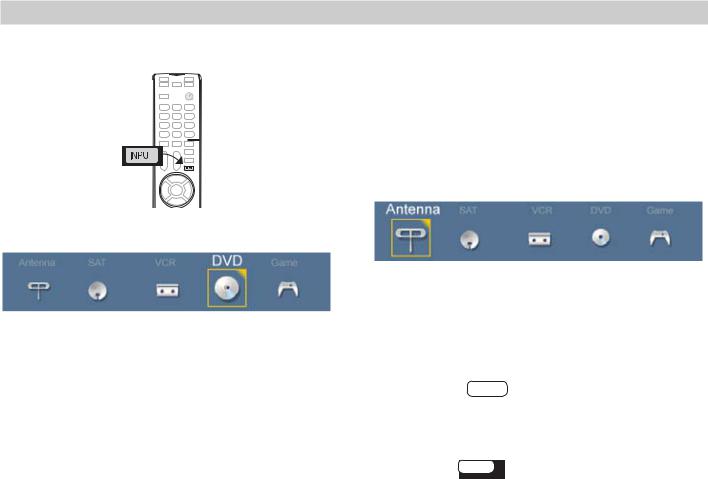
Selecting an Input to Watch
1. Press INPUT.
2. Press
 and
and to highlight an input icon.
Watching Broadcast TV
TV Connected to an Antenna or Direct Cable Service (no cable box)
Note: Perform channel memorization to enable reception of digital channels. See page 12.
1.Press INPUT to display the Input Selection menu.
2.Highlight the antenna or cable icon and press ENTER.
Sample Input selection menu, DVD input selected
3.Press ENTER to switch to the input.
4.To control the input device, use the device’s remote control or see “Introduction to Home-Theater Control,” page 46.
Note: In most cases, to see a named icon for a connected device (as in the samples), you must first assign a name either
•When the device is first connected and the
New Device Found menu offers a choice of names.
•By using the Inputs > Name menu to assign or change a name at any time after the TV has detected the connection.
More About the Input Selection Menu
•To assign helpful names to the icons, see the
Inputs > Name menu, page 57.
•To remove unwanted Antenna, Bluetooth®, or HDMI device icons from the Input Selection menu, see the Inputs > Name menu, page 57.
•To rearrange the icons, see the Inputs > Order menu, page 58.
Sample Input Selection menu, antenna input selected
3.To tune to a channel from the ANT input, use any of these methods.
•Enter the channel number using the number keys on the remote control and press ENTER.
For a two-part digital channel, such as 3-1, press 3 — 1 ENTER .
CANCEL
•Press CH to change channels one channel at a time.
•Press and hold CH to speed through channels.
•Press LAST to return to the previous channel.
•Use the Fav (Favorites) feature to tune to up to nine favorite channels. See page 28.
•Press GUIDE to display ChannelView channel listings, highlight a channel number, and press ENTER to tune.
•Set up ChannelView custom channel banks and use the CH key to tune to predefined groups of channels. See page 29.
For assistance call 1(800) 332-2119
1. Basic Setup and Operation |
15 |
Basic TV Operation, continued
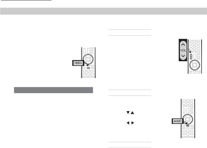
Picture Settings
1.To get the best picture under different viewing conditions, set the Picture Mode first before changing other video settings. See page 47.
a. Press VIDEO.
b. Press 
 until Picture Mode displays.
c. Press 
 to make one of these selections:
Name |
When to Use |
Brilliant |
Under bright light |
|
|
Game |
With gaming consoles (inputs |
|
named Game or PC only) |
Bright |
For most daytime viewing |
|
|
Natural |
For most nighttime viewing |
|
|
2.Press 
 to display the name of another adjustment.
3.Press 
 to make the adjustment.
4.Press EXIT to clear the display.
Additional picture options are available through these menus:
Picture > Video |
47 |
General picture appear- |
|
|
ance. |
|
|
|
Picture > Picture Plus |
48 |
Screensaver control |
|
|
and adjustments for |
|
|
movies |
|
|
|
Picture > Perfect |
49 |
Color fine-tuning |
(838 series) |
|
|
|
|
|
Picture > Advanced |
49 |
Advanced ISF color |
|
|
controls |
|
|
|
Picture > 3D Mode |
50, 33 |
3D video settings |
|
|
|
Basic Audio Controls
Controlling Sound Volume
• Press VOL to adjust the sound level of the TV speakers.
• See also “Controlling A/V Receiver Sound Volume” on page 31.
• 838 Series. Control subwoofer volume with an on-screen slider. See page 51. Set Sound > Global > Subwoofer to On to make this adjustment available.
Changing Audio Settings (TV Speakers Only)
1. |
Press AUDIO. |
|
2. |
Press |
to find the adjust- |
|
ment you want. See page 51. |
|
3. |
Press |
to change. |
Changing the Audio Output
To switch from the internal TV speakers to an external sound system,
1.Press AUDIO.
2.Press 
 to display the TV Speakers option.
3.Press 
 to change to Off.
TV Care
•Lamp Cartridge. When the lamp cartridge needs replacement, replace the lamp yourself and save the cost of a service call. See Appendix D, page 86, for instructions.
•General Cleaning. See “Cleaning Recommendations,” page 88.
Assistance
•For troubleshooting, service, and product support, see Appendix E, starting on page 89.
•For warranty information, see page 103.
For assistance call 1(800) 332-2119
16 |
1. Basic Setup and Operation |
Basic TV Operation, continued
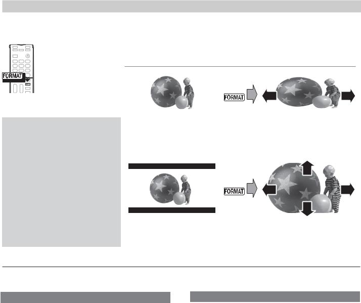
The FORMAT Key and Picture Shape
Repeatedly press the FORMAT key to cycle
through displays for the
current program. The
TV will remember the
format you last used on each input.
For details, see page 32
Important
Black bars at the edges of the screen are common in HD pictures. Black bars are not a defect of the TV.
•Black bars are added by broadcasters to fill the 16:9 screen area while preserving the original aspect ratio of the picture.
•Your cable box, satellite receiver, or other device may also be altering the broadcast picture.
If your device offers output in native format, try using it with Mitsubishi picture formats.
Sample Uses of the FORMAT Key
If you prefer to reduce of eliminate black areas at the edges of the picture, use the FORMAT key.
|
|
|
|
|
|
Press |
|
|
|
||
|
|
|
|
|
|
|
|
|
|
|
|
|
|
|
|
|
|
|
|
|
|
|
|
|
Squarish 4:3 image is |
|
Wide Expand mode stretches |
||||||||
|
narrower than the 16:9 |
|
the picture sideways to fill the |
||||||||
|
screen; unused areas at the |
|
screen. |
||||||||
|
sides are filled with black. |
|
|
|
|
|
|
||||
|
|
|
|
|
|
|
|
|
|
|
|
|
|
|
|
|
|
Press |
|
|
|||
|
|
|
|
|
|
|
|
||||
|
|
|
|
|
|
|
|
||||
|
|
|
|
|
|
|
|
|
|
|
|
|
|
|
|
|
|
|
|
|
|
|
|
|
|
|
|
|
|
|
|
|
|
|
|
|
Wide 2.35:1 anamorphic DVD |
|
Zoom mode. The picture fills |
||||||||
|
image; unused areas at the |
|
the screen. All four edges are |
||||||||
|
top and bottom are filled with |
|
cropped in this mode. |
||||||||
|
black (letterbox effect). |
|
|
|
|
|
|
||||
More TV Features
Feature |
Page |
Parental controls (Lock menu) |
59 |
|
|
Audio Lock (controls your sound system with |
76 |
the TV’s remote control left in TV mode.) |
|
|
|
TV Clock. Set the TV Clock if you plan to use the |
54 |
TV Timer (page 54) or ChannelView (page 29). |
|
|
|
Favorite channels or sources |
28 |
|
|
ChannelView and custom channel collections |
29 |
|
|
Changing the input names that appear in the |
57 |
Input Selection menu (Inputs > Name menu) |
|
|
|
3D Video |
33 |
|
|
StreamTV™ internet access |
43 |
|
|
Programming the remote control to operate |
75 |
other A/V devices |
|
|
|
For assistance call 1(800) 332-2119
Feature |
Page |
|
Digital camera images as composite video |
37 |
|
|
|
|
Controlling compatible devices using HDMI |
83 |
|
CEC control |
|
|
|
|
|
838 |
Series. Controlling A/V devices with Net- |
62 |
Command |
|
|
|
|
|
838 |
Series. Listening to a wireless audio |
38 |
device with the TV speakers |
|
|
|
|
|
838 |
Series. Using an external subwoofer. |
26 |
|
|
|
838 |
Series. Center and rear channel audio |
27 |
output |
|
|
|
|
|
1. Basic Setup and Operation |
17 |
Using the TV with a Personal Computer
Connecting a Computer to the TV
Use one of the connection methods listed below based on your computer’s video output.
Computer |
Video Connection |
Audio |
|
Video Output |
Connection |
||
|
|||
Digital DVI |
DVI-to-HDMI cable |
Stereo audio |
|
|
or an HDMI cable |
cables |
|
|
with a DVI-to-HDMI |
|
|
|
adapter |
|
|
|
|
|
|
HDMI |
HDMI-to-HDMI |
No additional |
|
|
cable |
audio connec- |
|
|
|
tion is required. |
|
|
|
|
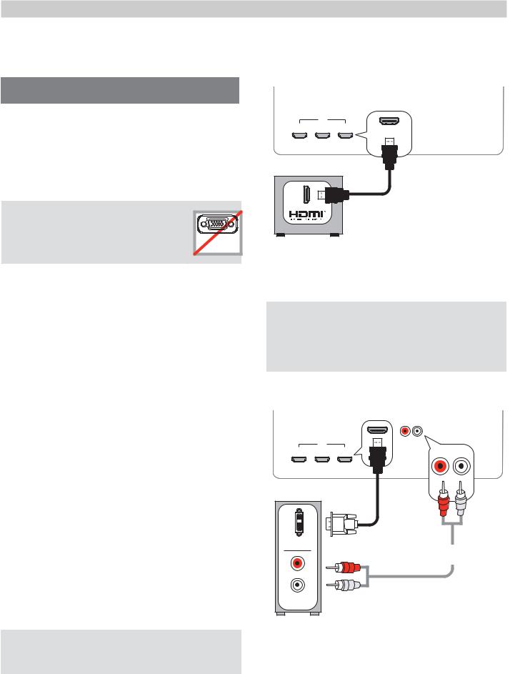
IMPORTANT |
|
|
This TV accepts digital computer |
|
|
video signals only. This TV is not |
VGA |
|
compatible with VGA (analog) |
||
PC MONITOR OUT |
||
computer video. |
||
|
1.Connect the computer’s digital video output to one of the TV’s HDMI jacks. See the connection
diagrams on this page for the method suited to your equipment.
2.Connect the computer’s audio output using one of these options:
•For digital DVI video signals, connect the analog audio output to the TV’s DVI/PC AUDIO INPUT jack.
•For HDMI signals, no additional audio connection is required.
Note: If you are unable to hear audio from the computer, there may be an incompatibility in the computer’s hardware, software, or internal settings. Consult a trained computer technician for advice.
3.Power on the TV and computer. The TV will detect the connection and display the New Device Found screen.
4.In the New Device Found screen, press 
 to highlight PC in the list of device types. It is important to use the name PC so that the TV processes the PC signal correctly.
5.Highlight EXIT and press ENTER to close the New Device Found screen.
Note: If your computer provides digital audio output (coaxial or optical), you can connect it directly to a digital A/V receiver and bypass the TV.
HDMI Connection
Mitsubishi recommends using high-speed HDMI cables to connect newer devices incorporating HDMI
TV main panel
HDMI-to-HDMI cable
Computer with HDMI output
An HDMI-to-HDMI connection carries all video and audio on a single cable.
HDMI and Digital Surround Sound
838 Series. The TV’s HDMI inputs can receive digital surround sound from an HDMI device. Use an HDMI connection if you want to hear digital surround sound from the TV’s internal speaker array.
DVI Video Connection
TV main panel
|
DVI-to-HDMI |
|
|
cable |
Stereo analog |
|
|
audio cables |
AUDIO |
Computer with DVI and |
|
|
stereo audio outputs |
|
A DVI connection from a personal computer requires a separate audio connection.
For assistance call 1(800) 332-2119

18 |
1. Basic Setup and Operation |
Using the TV with a Personal Computer
Computer Video Adjustments
1.Power on the computer.
2.Select PC from the Input Selection menu. To do this, press INPUT to open the Input Selection menu, move the highlight to the PC icon, and press ENTER.
3.Working from the computer, change the resolution of the computer image. View the computer image on the TV and maximize the computer
resolution while maintaining a suitable aspect ratio for the image.
Tip
Set the computer’s screen saver to display a pattern after several minutes of inactivity. This acts as a reminder that the TV is powered on and the lamp
is in use. The lamp is in use whenever the TV is powered on, even if the screen appears dark.
4.Perform TV video adjustments. Press VIDEO repeatedly to access videoadjustment options.
5.Press FORMAT repeatedly to find the picture shape best suited to the image. See the chart on this page showing how different computer resolutions can be displayed on the TV.
Distortion in Computer Images
Computer images may show distortion when viewed on the TV, e.g., lines that should be straight may appear slightly curved.
Image Resolution
Your Mitsubishi TV can display the resolutions shown in the chart from standard VGA (640 x 480) through 1920 x 1080 signals at a refresh rate of 60 Hz.
In most cases, the computer will select the best resolution match to display on the TV. You can override this setting if you wish. Refer to your computer operating system’s instructions for information on changing the screen resolution.
You may need to restart the computer for changes to take effect.
Computer Signal |
As Displayed on TV Screen |
||
Original Format |
4 X 3 |
16 X 9 |
|
Standard |
Standard |
|
|
|
|
||
|
|
|
|
VGA
640 X 480
SVGA
Original Format |
Standard |
Zoom |
XGA
1024 X 768
PC 720p
1280 X
WXGA 1360 X 768
SXGA
Original Format |
Standard |
Reduce |
PC 1080p
1920 X 1080
For assistance call 1(800) 332-2119

2 |
TV Connections |
19 |
|
||
|
|
|
|
|
Before You Begin
Auto Input Sensing
The TV’s Auto Input Sensing feature automatically recognizes many connections and prompts you to identify the type of device connected. See page 13 for more on Auto Input Sensing.
Connection Types
Use the connection types available on your input devices that will give the best video quality. For example, choose HDMI over component video; choose component video over composite video.
Picture Quality
For best picture quality, route signals directly from the source device to the TV whenever possible.
Surround Sound
•For best surround sound audio quality from an external sound system, route audio-carrying cables from the source device directly to your sound system.
•838 Series. To use the surround sound capabilities of the TV’s speaker array, you must connect your digital surround sound source to the TV on either
-- An HDMI input
-- The ANT antenna input
IMPORTANT
Accessory items such as cables, adapters, splitters, or combiners required for TV connections are not supplied with the TV. These items are available at most electronics stores.
Connection Types and Audio/Video Quality
|
|
|
|
|
|
|
|
|
|
VIDEO QUALITY |
|
|
|
|
|
|
|
AUDIO QUALITY |
|||||||||||||||||||
|
|
|
|
|
|
|
|
|
|
|
|
|
|
|
|
|
|||||||||||||||||||||
|
|
BEST |
|
|
|
|
GOOD |
|
|
|
BEST |
|
|
|
GOOD |
||||||||||||||||||||||
|
|
|
|
|
|
|
|
|
|
|
|
|
|
Component |
Composite |
|
|
|
|
Digital |
L/R Analog |
||||||||||||||||
HDMI HDMI-to-DVI |
|
|
Video |
Video |
|
HDMI |
Audio |
Audio |
|||||||||||||||||||||||||||||
|
|
|
|
|
|
|
|
|
|
|
|
|
|
|
|
|
|
|
|
|
|
|
|
|
|
|
|
|
|
|
|
|
|
|
|
|
|
|
|
|
|
|
|
|
|
|
|
|
|
|
|
|
|
|
|
|
|
|
|
|
|
|
|
|
|
|
|
|
|
|
|
|
|
|
|
|
|
|
|
|
|
|
|
|
|
|
|
|
|
|
|
|
|
|
|
|
|
|
|
|
|
|
|
|
|
|
|
|
|
|
|
|
|
|
|
|
|
|
|
|
|
|
|
|
|
|
|
|
|
|
|
|
|
|
|
|
|
|
|
|
|
|
|
|
|
|
|
|
|
|
|
|
|
|
|
|
|
|
|
|
|
|
|
|
|
|
|
|
|
|
|
|
|
|
|
|
|
|
|
|
|
|
|
|
|
|
|
|
|
|
|
|
|
|
|
|
|
|
|
|
|
|
|
|
|
|
|
|
|
|
|
|
|
|
|
|
|
|
|
|
|
|
|
|
|
|
|
|
|
|
|
|
|
|
|
|
|
|
|
|
|
|
|
|
|
|
|
|
|
|
|
|
|
|
|
|
|
|
|
|
|
|
|
|
|
|
|
|
|
|
|
|
|
|
|
|
|
|
|
|
|
|
|
|
|
|
|
|
|
|
|
|
|
|
|
|
|
|
|
|
|
|
|
|
|
|
|
|
|
|
|
|
|
|
|
|
|
|
|
|
|
|
|
|
|
|
|
|
|
|
|
|
|
|
|
|
|
|
|
|
|
|
|
|
|
|
|
|
|
|
|
|
|
|
|
|
|
|
|
|
|
|
|
|
|
|
|
|
|
|
|
|
|
|
|
|
|
|
|
|
|
|
|
|
|
|
|
|
|
|
|
|
|
|
|
|
|
|
|
|
|
|
|
|
|
|
|
|
|
|
|
|
|
|
|
|
|
For assistance call 1(800) 332-2119

20 |
2. TV Connections |
Inputs and Outputs
Main Connection Panel
CENTER INPUT
(838 series, page 51)
13
IR–NetCommand Output 14
(838 series, page 63)
|
HDMI |
|
1 |
2 |
3 |
SUBWOOFER |
DIGITAL |
|
Audio |
Audio/surround |
|||||
|
9b OUTPUT |
|
|||||||
|
OUTPUT |
|
|||||||
OUTPUT |
|
Audio |
DVI/PC AUDIO |
|
|||||
|
(838 series, page 25, |
||||||||
|
(738 series, |
||||||||
(838 series, |
OUTPUT |
INPUT |
|||||||
page 51) |
|
||||||||
page 25) |
|
||||||||
page 51) |
(page 25) |
(page 23) |
|
||||||
|
|
|
|||||||
|
|
|
|
||||||
12 |
|
11 |
|
10 |
9a |
AUDIO/SURROUND |
|||
|
|
R |
OUTPUT |
L |
|||||
CENTER |
SUB |
|
|
|
|
|
|
|
|
WOOFER |
|
|
|
|
|
|
|
||
INPUT |
OUTPUT |
|
|
|
|
|
|
|
|
|
|
|
DIGITAL |
DVI/PC AUDIO |
AUDIO |
|
|
|
|
|
|
|
AUDIO |
R INPUT L |
R OUTPUT |
L |
|
|
|
|
|
|
OUTPUT |
|
|
||||
IR-NetCommand |
|
|
|
|
|
|
|
|
|
Output/EXTERNAL |
|
|
|
|
|
|
|
||
CONTROLLER INPUT |
|
|
|
|
|
|
|
||
|
|
|
|
VIDE |
P |
2 |
3D |
|
|
|
|
|
|
|
|
INPUT |
|
||
|
|
LAN |
|
|
|
GLASSES |
|
||
|
|
|
|
|
|
|
EMITTER |
|
|
|
|
|
|
VIDE |
P |
INPUT 1 |
|
|
|
|
|
|
|
|
|
|
|||
|
|
|
R AUDIO L |
(480i / 480p / 720p / 1080i) |
|
|
|
||
1 |
2a |
3 |
HDMI |
USB |
LAN |
(page 22) |
(738 Series: power or |
(Ethernet, port |
|
wireless adapter, page 44; |
page 43) |
|
838 Series: power only, |
|
|
page 26 ) |
|
Auto Input Sensing
The TV’s Auto Input Sensing feature automatically recognizes some connections and prompts you to identify the device type. See page 13.
4 |
6 |
7 |
AUDIO |
Y/VIDEO Pb Pr |
3D GLASSES |
analog stereo |
(component |
EMITTER |
input |
video, page 23) |
(page 33) |
5 |
|
8 |
Y/VIDEO |
|
ANT |
(composite |
|
(page 24) |
video, page 24) |
|
|
Side Inputs
838 Series. A set of jacks is provided for a camcorder, game, or other audio/video device.
If you connect a DVI device to the side HDMI input, use the nearby audio jacks to send sound from the device to the TV.
Sound Projector Calibration
Microphone Input (page 41)
INPUT 3
Pr Pb Y/ VIDEO L AUDIO R USB HDMI 4
|
|
|
|
|
|
|
|
|
|
|
|
|
|
|
|
|
|
|
|
|
|
|
|
|
|
6 |
5 |
4 |
|
|
2b |
1 |
|||
|
|
|
|||||||||
|
|
Y/VIDEO Pb Pr |
Y/VIDEO |
AUDIO |
|
USB |
|
|
|
HDMI |
|
|
|
(component |
(composite |
analog |
(multi-use, |
|
(page 22) |
||||
|
|
video, page 23) |
video, page 24) |
stereo |
pages 26, |
|
|
|
|
||
|
|
|
|
|
|
||||||
|
|
input |
|
|
|
|
|||||
|
|
|
|
35, 44) |
|
|
|
|
|||
|
|
|
|
|
|
|
|
|
|
||
For assistance call 1(800) 332-2119
2. TV Connections |
21 |
Inputs and Outputs, continued
1. HDMI® Inputs (High-Definition Multimedia Interface)
The HDMI inputs support uncompressed standard and high-definition digital video formats, bitstream Dolby Digital 5.1, and PCM digital stereo audio. These inputs are HDCP (High-Bandwidth Digital Copy Protection) compliant.
Mitsubishi recommends you use high-speed HDMI cables to connect newer source devices incorporating HDMI technology. High-speed cables bring you the full benefits of Deep Color and x.v.Color.
These HDMI inputs can also accept digital DVI video signals. To connect a device’s DVI output to the TV’s HDMI input, use an HDMI-to-DVI adapter or cable plus an analog audio. Connect the audio cable to the DVI/PC AUDIO INPUT jack on the TV to receive audio from your DVI device.
Use the HDMI inputs to connect to CEA-861 HDMI compliant devices such as a high-definition receiver or DVD player. These inputs support 480i, 480p, 720p, 1080i, and 1080p video formats.
The TV’s HDMI inputs are compatible with many DVI-D and HDMI computer video signals.
HDMI Cable Categories
HDMI cables are available as Standard and High-Speed types.
•High-Speed HDMI Cables. Newer DVD players, video games, and set-top boxes require High-Speed HDMI cables, suitable for clock frequencies up to 340 MHz or data rates of up to 10.2 gigabits per second. Use high-speed cables for 1080p HD signals carrying extended color encodings (i.e., 30 or more bits, also called Deep Color). High-Speed HDMI cables are also suitable for standard HDTV signals.
•Standard HDMI Cables. Standard HDMI cables may be unmarked. They are suitable for standard HDTV 720p, 1080i, and 1080p signals with 8-bit color depth. Use Standard HDMI cables for clock frequencies up to 74.25 MHz or data rates of up to 2.23 gigabits per second.
2a. USB (limited use)
Standard USB 5-volt, 500-milliamp power output you can use to supply power to an accessory device.
738 Series. Use this port for a wireless network adapter. See page 44.
2b. USB (838 Series)
•The TV can read JPEG photo files and mp3 music files from a USB storage device connected to this input.
•Connect a compatible wireless adapter to stream internet content to the TV (page 43).
•This USB port can be used to power accessory devices.
3.LAN
Use the LAN Ethernet jack for streaming internet video to the TV. See page 43 for setup.
4. AUDIO
Analog stereo inputs for use in conjunction with adjacent composite or component video jacks.
5. Y/Video (Composite Video)
Analog standard-definition video inputs. Use the adjacent AUDIO R and L inputs if you wish to send audio to the TV speakers.
6. Y/VIDEO Pb Pr (Component Video)
Analog video inputs able to accept high-definition video from a high-definition source device. Use the adjacent AUDIO R and L inputs if you wish to send audio to the TV speakers.
7. 3D GLASSES EMITTER
Use this jack for the special IR emitter supplied with some 3D glasses. The emitter sends out an infrared signal that synchronizes your 3D glasses with the screen display. See page 33.
8. ANT (Antenna)
Connect your main antenna or direct cable service (without a cable box) to ANT. The ANT input can receive digital and analog over-the-air channels from a VHF/ UHF antenna or non-scrambled digital/analog cable source.
For assistance call 1(800) 332-2119
22 |
2. TV Connections |
Inputs and Outputs, continued
9a. AUDIO OUTPUT
Sends analog audio of the current program to an analog A/V surround sound receiver or stereo system. Digital audio from digital channels and HDMI devices is converted to analog audio by the TV for output on this jack. This is the only audio connection needed to the TV if using an analog A/V receiver or stereo system.
Note: If connecting headphones, set Sound > Global > Analog Audio Out to Variable.
9b. AUDIO/SURROUND OUTPUT
838 Series. Sends out analog audio as described for other models or can be set for rear surround sound. Connect external rear speakers to this output for a fuller surround sound effect from the TV’s speaker array, Set
Sound > Global > Analog Audio Out to Rear (see “External Rear Speakers” on page 42).
10. DVI/PC AUDIO INPUT
Connect a DVI device to one of the TV’s HDMI inputs and use this jack to send analog audio to the TV.
11. DIGITAL AUDIO OUTPUT
This output sends Dolby Digital or PCM digital audio to your digital A/V surround sound receiver. Incoming
analog audio is converted by the TV to PCM digital audio. If you have a digital A/V receiver, this is the only audio connection needed between the TV and your A/V receiver.
12. SUBWOOFER OUTPUT
838 Series. Connect a powered subwoofer to this input to complement effects from the TV’s speakers. Set Sound > Global > Subwoofer to On to enable this output (see “Adding a Subwoofer,” page 26).
13. CENTER INPUT
838 Series. Connect your A/V receiver’s center channel output to this input to make the TV speakers output center-channel sound. Set Sound > Global > Center Channel to On to enable this input. See “Using the TV Speakers as a Center Channel,” page 27.
14. IR-NetCommand Output
838 Series
As an output: Connect IR emitters to this jack to send NetCommand control signals to external IR-controlled devices.
As an input: Accepts control signals from an external controller when set up by your professional installer.
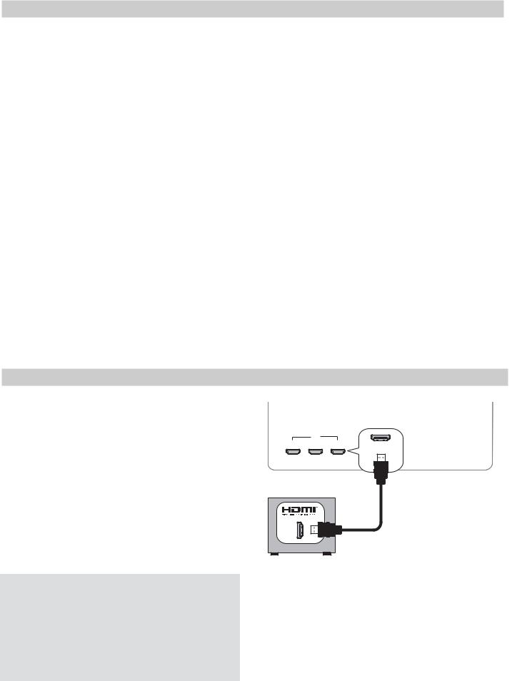
HDMI Device
Commonly used with an HDTV Cable Box, Satellite Receiver, or DVD/Blu-ray Player
Required: HDMI-to-HDMI cable.
Mitsubishi recommends using high-speed HDMI cables to connect newer devices incorporating HDMI technology. See “HDMI Cable Categories” on the previous page for more on HDMI cable types.
Connect an HDMI cable from the TV to the device’s HDMI output. HDMI-connectable devices provide video and audio through a single cable.
Note: The HDMI connection supports copy protection (HDCP).
HDMI and Digital Surround Sound
738 Series. The TV’s HDMI inputs can receive digital stereo audio signals only when using the TV speakers.
838 Series. The TV’s HDMI inputs can receive digital surround sound from an HDMI device. Use an HDMI connection if you want to hear digital surround sound from the TV’s internal speaker array.
For assistance call 1(800) 332-2119
HDMI
2 3
TV main panel
HDMI-to-HDMI cable
Any HDMI device

2. TV Connections |
23 |
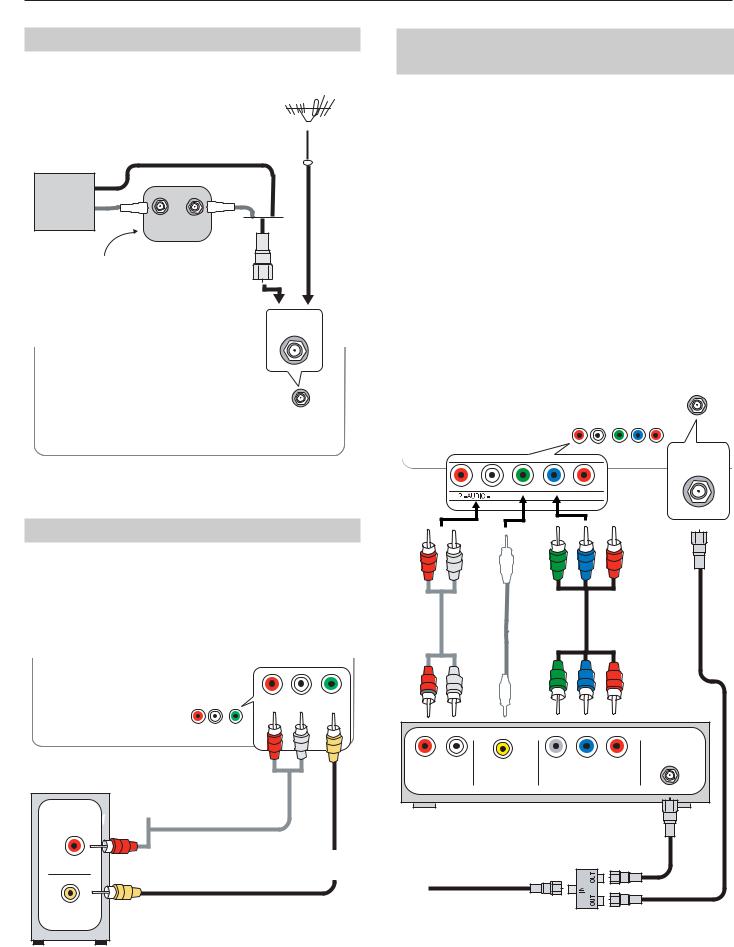
Y Pb Pr Component Video Device
Commonly used with an HDTV Cable Box, Satellite Receiver, or DVD/Blu-ray Player
If your source device has an HDMI output, use the connections for HDMI devices described on the opposite page instead of component video.
Required:
RCA-type component video cables Left/right analog audio cables.
Note: To hear digital surround sound from an A/V receiver, connect the digital audio output from the device directly to your digital A/V receiver.
TV main panel
Audio |
Component |
cables |
video cables |
Incoming from cable service or
CABLE IN or |
Component video |
SATELLITE IN |
device |
DVI Video Device
Commonly used with a Cable Box, Satellite Receiver, or DVD Player
Connect a DVI device (digital only) to one of the TV’s HDMI input jacks.
Required:
Analog stereo audio cables
DVI-to-HDMI cable or DVI/HDMI adapter and HDMI cable
If you are using a DVI/HDMI adapter, it is important to connect the adapter to the DVI device for best performance.
Some devices require connection to an analog input first in order to view on-screen menus and to select DVI as the ouput. Please review your equipment instructions for DVI connectivity and compatibility.
Note: The HDMI connection supports copy protection (HDCP).
DVI/PC AUDIO
R INPUT L
HDMI |
|
|
3 |
DVI/PC AUDIO |
|
|
||
|
R INPUT |
L |
L
TV main panel
|
DVI-to-HDMI |
Audio |
DVI OUT |
cable |
|
R |
|
cables |
|
|
L 
AUDIO
Digital DVI 
 device
For assistance call 1(800) 332-2119
24 |
2. TV Connections |
Antenna or Cable TV Service
Connect the incoming cable to the TV’s ANT input.
Antenna 
Direct cable (no cable box)
Cable TV |
or |
|
|
service |
|
IN |
OUT |
Older cable box |
|
Not recommeded. Other |
or |
connection types provide |
|
better quality audio and video. |
|
TV main panel |
ANT |
|
|
Composite Video Device
VCR or other device with composite video output
Required:
Composite video cable (usually yellow) Analog stereo audio cables.
R– AUDIO –L
VIDE
R AUDIO L
TV main panel
L 


RAudio cables
AUDIO OUT
COMPOSITE
VIDEO OUT VCR or other device with composite video output
Composite video cable
For assistance call 1(800) 332-2119
VCR or DVD Recorder to an
Antenna or Wall Outlet Cable
Required:
1.Video cables
1a. Component video cables (red/blue/green) or
1b. Composite video cable (usually yellow)
2.Left/right analog audio cables.
3.Two-way RF splitter
4.Two coaxial cables
Note:
•Use composite video only if component video or HDMI are unavailable.
•If your recording device has an analog-only tuner, you must use a digital converter box to enable recording of digital broadcasts.
ANT
TV main panel
VIDE P
R AUDIO L
ANT
VIDE P
|
Composite cablevideo |
1b. |
1a. |
2. |
or |
|
|
|
|
|
|
|
ANTENNA |
R |
L |
|
IN |
COMPOSITE |
COMPONENT |
||
AUDIO OUT |
VIDEO OUT |
VIDEO OUT |
|
DVD Recorder or VCR |
|
|
3. |
4. |
|
RF Splitter |
||
|
||
Incoming cable |
|
4.

2. TV Connections |
25 |
A/V Receiver
Most setups require either a digital audio cable or analog stereo audio cables. To send audio from TV channels received on the ANT input or devices connected directly to the TV, you must use one of the connections shown below.
The TV makes all audio available in digital and analog formats:
•Analog audio coming into the TV is available as output in digital stereo format on the DIGITAL AUDIO OUTPUT jack.
•Digital incoming audio is available as analog output on the AUDIO OUTPUT L and R jacks.
DIGITAL |
R |
AUDIO |
L |
AUDIO |
OUTPUT |
||
OUTPUT |
|
|
|
DIGITAL |
R |
AUDIO |
L |
AUDIO |
OUTPUT |
||
OUTPUT |
|
|
|
TV main panel
Digital coaxial |
or |
|
|
cable (for a digital |
|
A/V receiver) |
Stereo analog |
|
|
|
cables (for an |
|
analog A/V |
|
receiver) |
A/V Receiver with HDMI Output
Required: One HDMI-to-HDMI cable
This option allows you to view content from devices connected to an A/V receiver. The A/V receiver can send audio and video to the TV over a single HDMI cable. You can use an HDMI connection as described here in addition to an audio connection from the TV’s audio output. The optional audio connection allows you to hear, through the A/V receiver, devices connected to the TV only, e.g., an antenna on the ANT input.
•You may be able to use the TV’s remote control (in TV mode) to operate connected CEC-enabled
HDMI devices. Experiment with your equipment to determine which functions are available to the TV’s remote control. See Appendix C, page 83.
•838 Series: This setup allows you to use NetCom- mand-controlled audio and video switching over the HDMI cable. See “Automatic Audio/Video Switching Over an HDMI Connection” on page 70.
To use NetCommand to supplement HDMI control of a CEC-enabled A/V receiver, note the recommendations under “More About Using an HDMI Connection,” page 70.
|
|
|
R |
AUDIO |
L |
|
|
|
|
|
OUTPUT |
|
|
||
|
HDMI |
|
DIGITAL |
|
R |
AUDIO |
L |
1 |
2 |
3 |
|
OUTPUT |
|||
AUDIO |
|
|
|
|
|||
|
|
|
OUTPUT |
|
|
|
|
|
TV |
|
|
COAXIAL |
|
Optional |
|
HDMI cable |
analog or |
||
INPUT |
|||
|
digital audio |
||
|
|
||
|
|
connection |
|
A/V receiver back panel |
|
|
Note:
•On rare occasions, an HDMI signal may be copy-restricted and cannot be output from the TV as a digital signal. To hear these copy-
protected signals through the A/V receiver, use the connection for an analog A/V receiver.
A/V receiver with HDMI output
HDMI OUT |
DIGITAL |
R |
L |
|
AUDIO IN |
ANALOG AUDIO IN |
|
•Check the A/V receiver’s Owner’s Guide for information concerning use of the digital input and switching between digital sound and analog stereo sound from the TV.
Any connection |
VCR |
types |
|
High-definition |
|
DVD player |
DVD player |
|
|
|
Cable box |
For assistance call 1(800) 332-2119
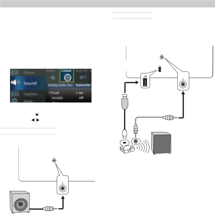
26 |
2. TV Connections |
Supplemental Audio Connections
838 Series. Add a subwoofer to complement the TV’s speaker array or use the TV’s speakers as a center channel for your external sound system.
Adding a Subwoofer
Add a subwoofer to complement the TV speakers with a fuller bass sound.
•After connecting a subwoofer, you must enable the TV’s subwoofer output in the TV’s Sound menu. Go to Sound > Global > Subwoofer and set it to On.
•To control subwoofer volume, press the AUDIO key
and then press |
to find the subwoofer volume |
slider. Press |
to change the volume. |
Subwoofer with Audio Cable
Connect the subwoofer directly to the TV’s SUBWOOFER OUTPUT.
SUB
WOOFER
OUTPUT
SUB
WOOFER
OUTPUT
Subwoofer with audio connection to TV.
Wireless Subwoofer
Mitsubishi recommends Polk Audio Wireless Subwoofer model PSW i8m. The transmitter module can be conveniently powered from the TV’s USB power port. Connect an audio cable to the transmitter to supply audio from the TV’s SUBWOOFER OUTPUT.
SUB
WOOFER
OUTPUT
Power-only |
|
USB port |
|
|
SUB |
|
WOOFER |
|
OUTPUT |
|
TV |
USB/USB |
RCA/RCA |
mini-plug |
audio cable |
power cable
Polk Audio PSW i8m powered wireless subwoofer
Setup to send audio signals wirelessly to the subwoofer.
For assistance call 1(800) 332-2119
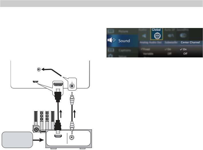
2. TV Connections |
27 |
Supplemental Audio Connections, continued
Using the TV Speakers as a Center Channel
If using an external surround sound system, you can make the TV’s speakers provide center channel sound. Your A/V receiver must have a center channel pre out that can supply an amplified center-channel signal to the TV.
1. Connect your A/V receiver’s HDMI output and
CENTER
INPUT
|
CENTER |
|
INPUT |
HDMI cable |
RCA/RCA |
audio cable |
A/V receiver with HDMI
output |
|
|
|
|
CENTER |
Surround sound |
HDMI OUT |
CHANNEL |
source device |
PRE OUT |
|
|
|
4.Enable the TV’s center channel mode:
a.Go to Sound > Global and set Center Channel to On.
b.Press the AUDIO key and press to display the TV Speakers option. Press
  to select
Center.
5.To balance volume:
a.Power on the A/V receiver and TV.
b.Compare the volume of the TV’s center channel with the rest of the sound system. If the TV volume needs adjustment,
i.Turn on the TV speakers. Press AUDIO and
press to display the TV Speakers option. Press
  to select On.
ii.Adjust TV volume using the VOL key.
iii.Return the TV to center channel mode.
Press AUDIO and press to display the TV Speakers option. Press
  to select
Center.
iv.Compare the sound volume. Repeat this adjustment if needed.
2.Turn on the A/V receiver’s center channel pre out if needed. See the A/V receiver’s instruction manual.
3.Press the VOL key to adjust TV volume to about level 30.
For assistance call 1(800) 332-2119
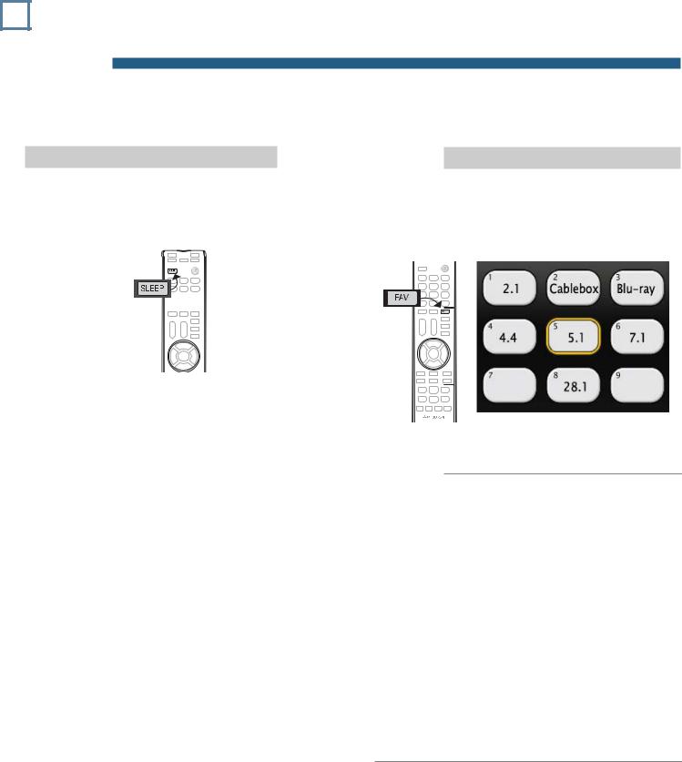
28 3 TV Features
Sleep Timer
The Sleep Timer turns the TV off after the length of time you set. To set the TV to turn on at a certain time of day, see the Setup > Timer menu on page 54.
Setting the Sleep Timer
1.Press SLEEP.
2.Press SLEEP additional times to increase the time in 30-minute increments up to the maximum of 120 minutes.
3.Press EXIT to clear the screen immediately. Otherwise the screen will clear after five seconds of inactivity.
Viewing or Changing the Sleep Timer
1.Press SLEEP to display the on-screen message.
2.Press SLEEP additional times to change the time before the TV powers off. To cancel the Sleep Timer, press SLEEP repeatedly until OFF is displayed.
FAV (Favorite Channels)
The FAV key gives you quick access to favorite program sources. Sources can be channels from the ANT input or devices connected to the TV. You can store up to nine favorites.
Sample Favorites menu. Switch to favorite channels or inputs using number keys.
|
1. |
Press INPUT and switch the TV to the input |
||
|
|
you want to add. If adding a channel, switch |
||
Adding |
|
to the ANT input and tune to the channel. |
||
3. Move the highlight to the number position |
||||
|
2. |
Press the FAV key. |
||
|
|
you want to assign to the channel or input. |
||
|
4. |
Press ENTER. |
||
|
|
|
|
|
Removing |
1. |
While watching TV, press the FAV key. |
||
2. |
In the Favorites menu, highlight the channel |
|||
|
||||
|
|
or input you want to remove. |
||
|
3. |
Press CANCEL. |
||
|
|
|
|
|
Selecting |
1. |
While watching TV, press the FAV key. |
||
2. |
Move the highlight to the item you want and |
|||
|
||||
press ENTER. For a shortcut, just press the number key for the channel or input.
For assistance call 1(800) 332-2119
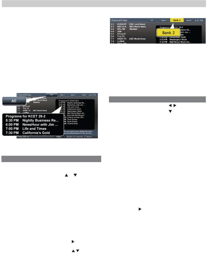
3. TV Features |
29 |
ChannelView Channel Listings
ChannelView displays program descriptions sent by broadcasters. This information may be unavailable in some areas.
About ChannelView
ChannelView™ shows memorized channels on the ANT input. It displays channel names and program information for digital channels. No program information is displayed for analog channels. See “Memorizing Channels with Channel Scan,” page 12 if needed.
ChannelView allows you to set up three banks of custom channels for convenient access. You can save groups of channels by content (e.g., news, sports, children’s programming) or by TV user.
Note: You must first set the TV Clock (page 54) to receive ChannelView listings.
ChannelView, “All” tab. Programs are listed on the right.
Using ChannelView Listings
Task |
Action |
|
|
Display/hide ChannelView |
Press GUIDE. |
|
|
listings (ANT input only). |
|
|
|
Move through channels |
Press or . |
||
one by one. |
|
|
|
|
|
|
|
Move through channels |
Press CH. |
|
|
quickly. |
|
|
|
|
|
||
Jump to listings for a spe- |
Enter the channel number. |
||
cific channel. |
Press CANCEL to add a |
||
|
dash; press twice to clear |
||
|
the channel number. |
||
|
|
|
|
Tune to a highlighted |
Press ENTER. |
|
|
channel. |
|
|
|
|
|
||
Update program informa- |
Press the INFO key (the |
||
tion for a highlighted digital |
screen may briefly go |
||
channel. |
blank). |
|
|
Display program descrip- |
1. |
Press |
to move into |
tions, if available. The |
|
the program area. |
|
description will appear at |
2. |
Press |
to move |
the bottom of the screen. |
|
between programs. |
|
Display more program |
Press INFO. |
|
|
description for the current |
|
|
|
channel (if available). |
|
|
|
|
|
|
|
ChannelView Custom Channel Banks
Select a channel bank to customize.
1.Press GUIDE to display ChannelView.
2.Press MENU to move the highlight to the bank header.
3.Press to select Bank 1, 2, or 3.
4.With the bank name highlighted, press ENTER to enter setup mode where you can select channels to include in the bank.
5.Press EXIT when finished with setup.
Task |
Action |
|
Move between banks |
Press |
. |
|
|
|
Move into the channel list |
Press . |
|
|
|
|
Add or delete a channel |
• Highlight the channel |
|
from the bank |
and press ENTER. A |
|
|
check indicates the |
|
|
channel has been |
|
|
added. |
|
|
• Press ENTER again to |
|
|
clear the check and |
|
|
remove the channel. |
|
|
|
|
Remove all channels |
Press CANCEL. |
|
from the selected bank |
|
|
|
|
|
Enter or exit setup mode |
Press MENU. |
|
|
|
|
Using Custom Channel Banks
•While watching TV, press CH. The TV will tune only to channels stored in the current bank.
•To change to a different channel bank:
1.Press GUIDE.
2.Press MENU.
3.Press .
.
4.Press EXIT.
•To allow tuning to any channel in memory, select the All bank.
For assistance call 1(800) 332-2119
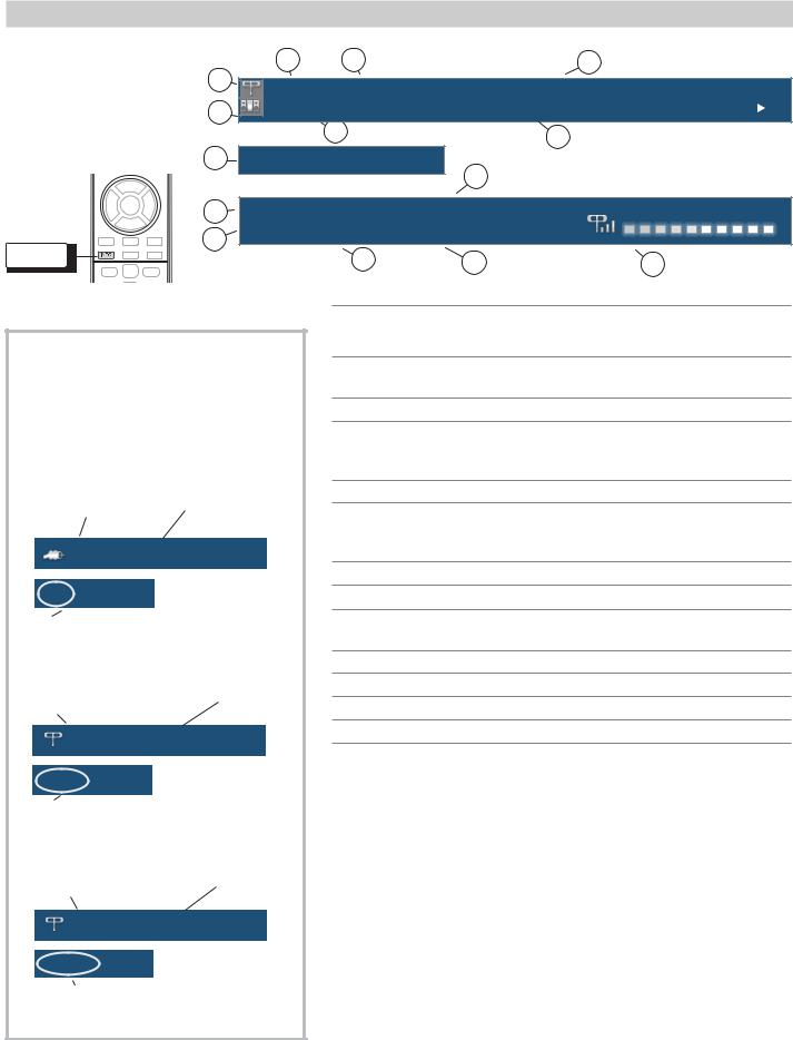
30 |
3. TV Features |
Status Display
Press the INFO key to see the on-screen status display. The most common displays are shown here.
INFO
|
3 |
4 |
|
6 |
1 |
402-101 KABC |
Monday Night Football |
||
|
||||
2 |
TV-PG DLSV |
St. Louis vs. Tampa Bay, played in Tampa for |
||
|
|
|
|
|
|
5 |
|
|
7 |
|
|
|
|
|
8 |
Sleep 30 min |
|
|
Sample information from the |
|
13 |
on-screen status display |
||
|
|
|
||
|
|
|
|
|
9 |
Tuesday 9:10 PM |
English |
|
|
10 |
HD 1080i Standard |
Surround |
|
|
|
|
|
|
|
|
|
11 |
12 |
14 |
About Channel Numbers
Channel Numbers for Over-the-Air Reception or Reception by Direct Cable
Note: All signals are automatically converted to 1080p for display.
Standard-Definition Analog Channels
Cable Reception |
|
Channel 3 |
Cable |
3 |
|
480i Stretch
Receiving Standard-Definition
Analog Signal (480i)
Standard-Definition Digital Channels
Over-the-Air |
|
Main Channel 7 |
Antenna Reception |
|
Sub-Channel 1 |
Ant |
7-1 KABC-SD |
|
SD 4:3 Stretch
Receiving Standard-Definition
Digital Signal (SD)
High-Definition Digital Channels
Over-the-Air |
|
Main Channel 7 |
Antenna Reception |
|
Sub-Channel 1 |
Ant |
7-1 KABC-HD |
|
HD 16:9 Standard
Receiving High-Definition
Digital Signal (HD)
1.Current Input
2.Audio Indicator. Key:
 TV speakers
  External sound system
  Mute
Mute
3.Channel number (antenna source only)
Digital channel includes major and sub-channel numbers.
4.Digital channel name (if broadcast); antenna source only.
5.V-Chip rating
•Antenna source only for digital signal
•Antenna or VIDEO composite jack for analog signal
6.Program name (if broadcast); digital source only
7.Program description (if broadcast); digital source, antenna only. Press the INFO key additional times to see more of the description.
8.Sleep Timer remaining time
9.Day and time
10.Signal type being received. See “Signal Definitions” on this page.
11.Screen format in use
12.Program audio indicator (antenna source only)
13.Available language (digital source, antenna only)
14.Signal-strength indicator (digital source, antenna only)
Signal Definitions
480i: Standard-definition, older type interlaced signals from the ANT input, composite VIDEO, component Y Pb Pr, or HDMI jacks.
480p: Standard-definition progressive-scan DVD signals on component
Y Pb Pr or HDMI jacks.
720p and 1080i: High-definition signals received through component Y Pb Pr or HDMI jacks. These signals are always 16:9 (widescreen).
1080p: High-definition signals from a PC or Blu-ray player; HDMI inputs only.
SD 4:3: Standard-definition squarish-screen-format signals from digital channels on the ANT input.
SD 16:9: Standard-definition widescreen-format signals from digital channels on the ANT input.
HD 16:9: High-definition 16:9 widescreen signals from digital channels on the ANT input.
For assistance call 1(800) 332-2119
Loading...