


SPLIT-TYPE, HEAT PUMP AIR CONDITIONERS
October 2005
No.OC322
REVISED EDITION-A
DATA BOOK
R410A
HFC
utilized
R410A
Outdoor unit |
|
[model names] |
[Service Ref.] |
SUZ-KA25VA |
SUZ-KA25VA.TH |
SUZ-KA35VA |
SUZ-KA35VA.TH |
SUZ-KA25VAH |
SUZ-KA25VAH.TH |
SUZ-KA35VAH |
SUZ-KA35VAH.TH |
SUZ-KA50VA |
SUZ-KA50VA.TH |
SUZ-KA60VA |
SUZ-KA60VA.TH |
SUZ-KA71VA |
SUZ-KA71VA.TH |
Revision:
•SUZ-KA71VA.TH is added in REVISED EDITION-A.
•Some descriptions have been modified.
•Please void OC322.
CONTENTS
1. COMBINATION OF INDOOR AND OUTDOOR UNITS ·····
2. TECHNICAL CHANGES ··············
3. PART NAMES AND FUNCTIONS··········
4. SPECIFICATION·················
 Indication of
model name 5. NOISE CRITERIA CURVES ············
6. OUTLINES AND DIMENSIONS ···········
7. WIRING DIAGRAM ················
8. REFRIGERANT SYSTEM DIAGRAM ········
9. PERFORMANCE CURVES ·············
10. ACTUATOR CONTROL··············
11. SERVICE FUNCTIONS···············
SUZ-KA25VA(H).TH SUZ-KA35VA(H).TH
12. TROUBLESHOOTING···············
13. DISASSEMBLY INSTRUCTIONS··········
14. PARTS LIST···················
NOTE:
This service manual describes technical data of the outdoor units.
•As for indoor units SLZ-KA25/35/50VA(L).TH and SEZKA35/50/60/71VA.TH, refer to the service manual OC320 and OC321.
1 
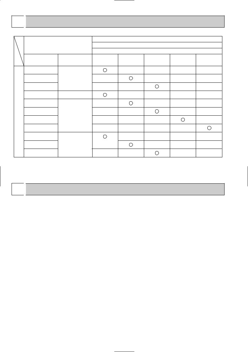
 COMBINATION OF INDOOR AND OUTDOOR UNITS
|
|
|
|
|
Outdoor unit |
|
|
|
Indoor unit |
|
|
Heat pump type |
|
||
|
|
|
|
|
SUZ- |
|
|
|
Service Ref. |
Service |
KA25VA(H).TH KA35VA(H).TH KA50VA.TH |
KA60VA.TH |
KA71VA.TH |
||
|
Manual No. |
||||||
|
|
|
|
|
|
|
|
|
SLZ-KA25VA(L).TH |
|
|
— |
— |
— |
— |
|
SLZ-KA35VA(L).TH |
OC320 |
— |
|
— |
— |
— |
heater |
SLZ-KA50VA(L).TH |
|
— |
— |
|
— |
— |
SEZ-KC25VA.W |
— |
|
— |
— |
— |
— |
|
electric |
|
||||||
SEZ-KA35VA.TH |
|
— |
|
— |
— |
— |
|
SEZ-KA50VA.TH |
|
— |
— |
|
— |
— |
|
without |
OC321 |
|
|||||
SEZ-KA60VA.TH |
— |
— |
— |
|
— |
||
|
|
||||||
SEZ-KA71VA.TH |
|
— |
— |
— |
— |
|
|
pump |
|
|
|||||
MFZ-KA25VA-E1 |
|
|
— |
— |
— |
— |
|
Heat |
MFZ-KA35VA-E1 |
OB409 |
— |
|
— |
— |
— |
MFZ-KA50VA-E1 |
|
— |
— |
|
— |
— |
|
|
|
|
|||||
(NOTE)
Only the combination data of SLZ type and SEZ type have been described in this manual. Please refer to the service manual of indoor unit or the technical data book for other combination.
2 
 TECHNICAL CHANGES
SUZ-A09VR.TH SUZ-KA25VA.TH
SUZ-A12VR.TH SUZ-KA35VA.TH
1.Indication of capacity has been changed.(BTU base kW base) 2.Control method between indoor and outdoor unit has been changed.
3.Power supply method has been changed (change to supply from outdoor unit). 4. Terminal block for power supply has been added.
5.Power P.C.board has been changed. 6.Inverter P.C. board has been changed. 7.Refrigerant circuit has been changed.
•Compressor has been changed.(KNB073FBVH KNB073FDVH:SUZ-KA25VA) (KNB092FAAH KNB092FCAH:SUZ-KA35VA)
•Specification and position of muffler have been changed.
•Path of outdoor heat exchanger has been changed.
•4-way valve and R.V. coil have been changed.
•Stop valve has been changed.
8.Fan motor has been changed.(AC DC) 9.Shape of grille has been changed. 10.Shape of service panel has been changed. 11.Shape of propeller has been changed.
12.Symbol on terminal block has been changed (to S1/S2/S3).
SUZ-A18VR SUZ-KA50VA.TH
SUZ-A24VR SUZ-KA60VA.TH
1.Indication of capacity has been changed.(BTU base kW base)
2.Power supply method has been changed (change to supply from outdoor unit). 3.Outdoor electronic control P.C. board has been changed.
4.Noise filter P.C. board has been changed. 5.Length of fan motor lead wire been changed. 6.Shape of relay panel has been changed.
7.Symbol on terminal block has been changed (to S1/ S2/ S3). 8.Control method between indoor and outdoor unit has been changed.
2

INFORMATION FOR THE AIR CONDITIONER WITH R410A REFRIGERANT
•This room air conditioner adopts an HFC refrigerant (R410A) which never destroys the ozone layer.
•Pay particular attention to the following points, though the basic installation procedure is same as that for R22 conditioners. 1 As R410A has working pressure approximate 1.6 times as high as that of R22, some special tools and piping parts/
materials are required. Refer to the table below.
2 Take sufficient care not to allow water and other contaminations to enter the R410A refrigerant during storage and installation, since it is more susceptible to contaminations than R22.
3 For refrigerant piping, use clean, pressure-proof parts/materials specifically designed for R410A. (Refer to 2. Refrigerant piping.)
4 Composition change may occur in R410A since it is a mixed refrigerant. When charging, charge liquid refrigerant to prevent composition change.
Refrigerant
Refrigerating |
oil |
|
New refrigerant |
Previous refrigerant |
Refrigerant |
R410A |
R22 |
|
|
|
Composition (Ratio) |
HFC-32: HFC-125 (50%:50%) |
R22 (100%) |
|
|
|
Refrigerant handling |
Pseudo-azeotropic refrigerant |
Single refrigerant |
|
|
|
Chlorine |
Not included |
Included |
|
|
|
Safety group (ASHRAE) |
A1/A1 |
A1 |
|
|
|
Molecular weight |
72.6 |
86.5 |
|
|
|
Boiling point (:) |
-51.4 |
-40.8 |
Steam pressure [25:](Mpa) |
1.557 |
0.94 |
Saturated steam density [25:](Kg/K) |
64 |
44.4 |
Combustibility |
Non combustible |
Non combustible |
|
|
|
ODP w1 |
0 |
0.055 |
|
|
|
GWP w2 |
1730 |
1700 |
|
|
|
Refrigerant charge method |
From liquid phase in cylinder |
Gas phase |
|
|
|
Additional charge on leakage |
Possible |
Possible |
Kind |
Incompatible oil |
Compatible oil |
|
|
|
Color |
Non |
Light yellow |
|
|
|
Smell |
Non |
Non |
|
|
|
w1 :Ozone Destruction Parameter |
: based on CFC-11 |
w2 :Global Warmth Parameter |
: based on CO2 |
Compressor
|
New Specification |
Current Specification |
|||||||||||||
The incompatible refrigerating oil easily separates from |
Since refrigerant and refrigerating oil are compatible each, |
||||||||||||||
refrigerant and is in the upper layer inside the suction muffler. |
refrigerating oil backs to the compressor through the lower |
||||||||||||||
Raising position of the oil back hole enables to back the |
position oil back hole. |
||||||||||||||
refrigerating oil of the upper layer to flow back to the |
|
|
|
|
|
|
|
||||||||
compressor. |
|
|
|
|
|
|
Suction muffler |
|
|
|
|
|
|
Suction muffler |
|
|
|
|
|
|
|
|
|
|
|
|
|||||
|
|
|
|
|
|
|
Oil back hole |
|
|
|
|
|
|
|
|
Compressor |
|
|
|
|
|
|
Compressor |
|
|
||||||
|
|
|
|
|
|
|
|
Refrigerating oil |
|
|
|
|
|
|
Oil back hole |
|
|
|
|
|
|
|
|
|
|
|
|
|
|
||
|
|
|
|
|
|
|
|
||||||||
Refrigerating oil /Refrigerant
NOTE : The unit of pressure has been changed to MPa on the international system of units(SI unit system). The conversion factor is: 1(MPa [Gauge]) =10.2(kgf/f [Gauge])
3
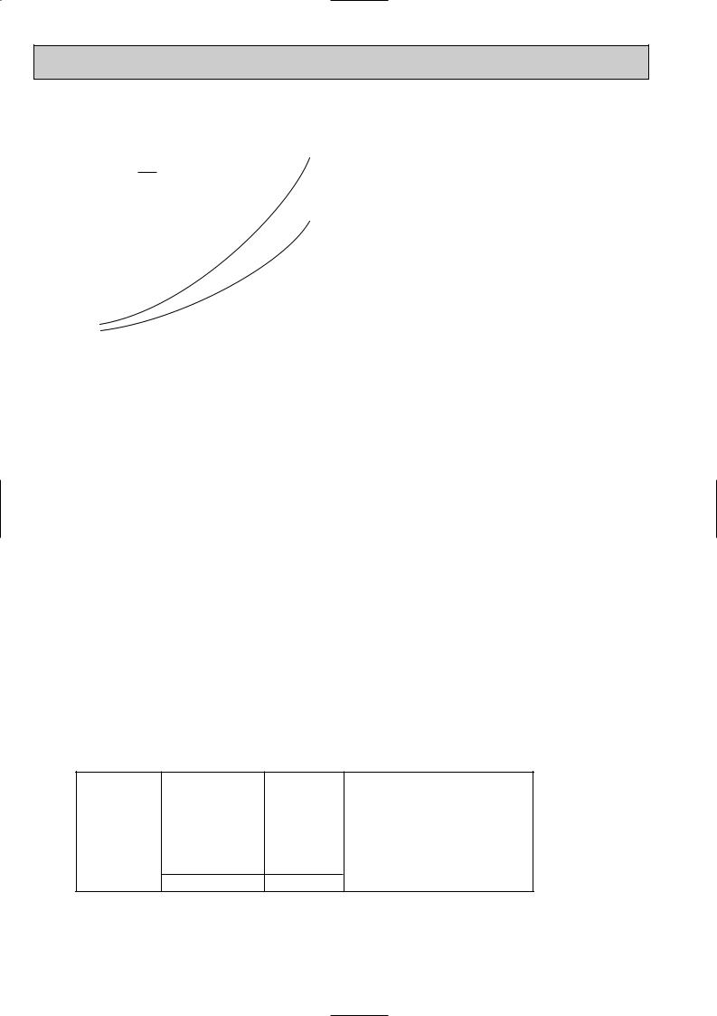
Conversion chart of refrigerant temperature and pressure
(MPa [Gauge]) |
|
|
|
|
|
|
|
|
|
|
|
|
|||
|
4.0 |
|
|
|
|
|
|
|
|
|
|
|
|
|
|
|
3.5 |
|
|
|
|
|
|
|
|
|
|
|
|
|
|
pressure |
|
|
|
|
|
R410A |
|
|
|
|
|
|
|||
|
|
|
|
|
|
|
|
|
|
|
|||||
|
|
|
|
|
|
|
|
|
|
|
|
||||
3.0 |
|
|
|
|
|
R22 |
|
|
|
|
|
|
|||
|
|
|
|
|
|
|
|
|
|
|
|
||||
liquid |
2.5 |
|
|
|
|
|
|
|
|
|
|
|
|
|
|
|
|
|
|
|
|
|
|
|
|
|
|
|
|
||
|
|
|
|
|
|
|
|
|
|
|
|
|
|
||
2.0 |
|
|
|
|
|
|
|
|
|
|
|
|
|
NOTE : The unit of pressure has been changed to MPa on the |
|
|
|
|
|
|
|
|
|
|
|
|
|
|
|||
1.5 |
|
|
|
|
|
|
|
|
|
|
|
|
|
||
Saturated |
|
|
|
|
|
|
|
|
|
|
|
|
|
||
1.0 |
|
|
|
|
|
|
|
|
|
|
|
|
|
international system of units(SI unit system). |
|
|
|
|
|
|
|
|
|
|
|
|
|
|
|
||
|
|
|
|
|
|
|
|
|
|
|
|
|
|
The conversion factor is: 1(MPa [Gauge]) =10.2(kgf/f [Gauge]) |
|
|
|
|
|
|
|
|
|
|
|
|
|
|
|
||
|
0.5 |
|
|
|
|
|
|
|
|
|
|
|
|
|
|
|
|
|
|
|
|
|
|
|
|
|
|
|
|
|
|
|
|
|
|
|
|
|
|
|
|
|
|
|
|
|
|
|
0.0 |
|
|
|
|
|
|
|
|
|
|
|
|
|
|
|
|
|
|
|
|
|
|
|
|
|
|
|
|
|
|
|
-0.5 |
|
|
|
|
|
|
|
|
|
|
|
|
|
|
|
-30 -20 |
-10 0 10 20 30 40 50 60 (:) |
|||||||||||||
1. Tools dedicated for the air conditioner with R410A refrigerant
The following tools are required for R410A refrigerant. Some R22 tools can be substituted for R410A tools.
The diameter of the service port on the stop valve in outdoor unit has been changed to prevent any other refrigerant being charged into the unit. Cap size has been changed from 7/16 UNF with 20 threads to 1/2 UNF with 20 threads.
R410A tools |
Can R22 tools be used? |
Description |
|
|
|
R410A has high pressures beyond the measurement range of existing |
|
Gauge manifold |
No |
gauges. Port diameters have been changed to prevent any other refrigerant |
|
|
|
from being charged into the unit. |
|
|
|
|
|
Charge hose |
No |
Hose material and cap size have been changed to improve the pressure |
|
resistance. |
|||
|
|
||
Gas leak detector |
No |
Dedicated for HFC refrigerant. |
|
|
|
|
|
Torque wrench |
Yes |
6.35 mm and 9.52 mm |
|
No |
12.7 mm and 15.88 mm |
||
|
|||
|
|
|
|
Flare tool |
Yes |
Clamp bar hole has been enlarged to reinforce the spring strength in the tool. |
|
|
|
|
|
Flare gauge |
New |
Provided for flaring work (to be used with R22 flare tool). |
|
Vacuum pump |
New |
Provided to prevent the back flow of oil. This adapter enables you to use |
|
adapter |
vacuum pumps. |
||
|
|||
Electronic scale for |
New |
It is difficult to measure R410A with a charging cylinder because the |
|
refrigerant charging |
refrigerant bubbles due to high pressure and high-speed vaporization |
||
|
|||
|
|
|
No : Not Substitutable for R410A Yes : Substitutable for R410A
2. Refrigerant piping
1Specifications
Use the refrigerant pipes that meet the following specifications.
Pipe |
Outside diameter |
Wall thickness |
Insulation material |
|
mm |
mm |
|||
|
|
|||
|
|
|
|
|
For liquid |
6.35 |
0.8 |
|
|
|
|
Heat resisting foam plastic |
||
9.52 |
0.8 |
|||
|
||||
|
9.52 |
0.8 |
Specific gravity 0.045 Thickness |
|
For gas |
|
|
8 mm |
|
12.7 |
0.8 |
15.881.0
•Use a copper pipe or a copper-alloy seamless pipe with a thickness of 0.8 mm. Never use any pipe with a thickness less than 0.8mm, as the pressure resistance is insufficient.
4

2Flaring work and flare nut
Flaring work for R410A pipe differs from that for R22 pipe.
For details of flaring work, refer to Installation manual “FLARING WORK”.
Pipe diameter (mm) |
Dimension of flare nut (mm) |
|
|
|
|
|
R410A |
R22 |
6.35 |
17 |
17 |
9.52 |
22 |
22 |
12.7 |
26 |
24 |
15.88 |
29 |
27 |
|
|
|
3. Refrigerant oil
Apply the special refrigeration oil (accessories: packed with indoor unit) to the flare and the union seat surfaces.
4.Air purge
•Do not discharge the refrigerant into the atmosphere.
Take care not to discharge refrigerant into the atmosphere during installation, reinstallation, or repairs to the refrigerant circuit.
•Use the vacuum pump for air purging for the purpose of environmental protection.
5.Additional charge
For additional charging, charge the refrigerant from liquid phase of the gas cylinder.
If the refrigerant is charged from the gas phase, composition change may occur in the refrigerant inside the cylinder and the outdoor unit. In this case, ability of the refrigerating cycle decreases or normal operation can be impossible. However, charging the liquid refrigerant all at once may cause the compressor to be locked. Thus, charge the refrigerant slowly.
Indoor unit
Refrigerant gas cylinder operating valve
Union
|
Stop valve |
Liquid pipe |
|
Gas pipe |
Outdoor unit |
Service port
Gauge manifold valve (for R410A)
 Charge hose (for R410A)
Refrigerant gas cylinder for R410A with siphon
Refrigerant (liquid)
Electronic scale for refrigerant charging
5

3 
 PART NAMES AND FUNCTIONS
SUZ-KA25VA.TH SUZ-KA35VA.TH SUZ-KA25VAH.TH SUZ-KA35VAH.TH
OUTDOOR UNIT
ACCESSORIES
Air inlet |
|
|
(back and side) |
|
|
Piping |
|
SUZ-KA25VA(H).TH |
|
|
|
Drain hose |
|
SUZ-KA35VA(H).TH |
Air outlet |
1 Drain socket |
1 |
|
|
Drain outlet
SUZ-KA50VA.TH SUZ-KA60VA.TH SUZ-KA71VA.TH
OUTDOOR UNIT
Air inlet (back and side)
Piping
Drain hose
ACCESSORIES
|
|
SUZ-KA50VA.TH |
|
|
SUZ-KA60VA.TH |
|
|
SUZ-KA71VA.TH |
1 |
Drain socket |
1 |
2 |
Drain cap [33 |
2 |
Air outlet
Drain outlet
6
4 
 SPECIFICATION
SLZ-KA•VA(L).TH / SUZ-KA•VA(H).TH
Outdoor Service Ref.
Function
Power supply
Capacity |
Air flow(High/Loww) |
K /h |
|
|
Capacity Rated frequency(Min.~Max.) |
kW |
|
Electrical data |
Dehumidification |
|
r/h |
Fan motor current 1 |
A |
||
|
Starting current |
1 |
A |
|
Compressor motor current 1 |
A |
|
Coefficient of performance (C.O.P) 1
Compressor |
resistance(at 20:) |
|
||
|
|
Model |
|
|
|
|
Output |
W |
|
|
|
Winding |
" |
|
|
|
|
||
Fan |
motor |
Model |
|
|
Winding |
" |
|||
|
|
|
||
|
|
resistance(at 20:) |
|
|
|
|
Dimensions WOHOD |
mm |
|
|
|
Weight |
kg |
|
|
|
Sound level 1 |
dB |
|
|
|
Fan speed(Highw/Loww, Highw/Medw/Loww) |
rpm |
|
|
|
Fan speed regulator |
|
|
|
|
Refrigerant filling |
kg |
|
|
|
capacity(R410A) |
||
|
|
|
||
Special |
remarks |
Refrigerating oil (Model) |
cc |
|
Thermistor RT61 (at 0:) |
k" |
|||
|
|
|||
|
|
Thermistor RT62 (at 100:) |
k" |
|
|
|
Thermistor RT64 (at 50:) |
k" |
|
|
|
Thermistor RT65 (at 25:) |
k" |
|
|
|
Thermistor RT61 (at 25:) |
k" |
|
|
|
Thermistor RT62 (at 100:) |
k" |
|
|
|
Thermistor RT64 (at 50:) |
k" |
|
|
|
Thermistor RT65 (at 25:) |
k" |
|
|
|
Thermistor RT68 (at 25:) |
k" |
|
SUZ-KA25VA(H).TH |
SUZ-KA35VA(H).TH |
SUZ-KA50VA.TH |
|||
Indoor Service Ref. |
Indoor Service Ref. |
Indoor Service Ref. |
|||
SLZ-KA25VA(L).TH |
SLZ-KA35VA(L).TH |
SLZ-KA50VA(L).TH |
|||
Cooling |
Heating |
Cooling |
Heating |
Cooling |
Heating |
Single phase |
Single phase |
Single phase |
|||
230V,50Hz |
230V,50Hz |
230V,50Hz |
|||
2.5(0.9-3.2) 3.0(0.9-4.5) |
3.5(1.0-3.9) 4.0(0.9-5.0) |
4.6(1.1-5.2) 5.0(0.9-6.5) |
|||
0.5 |
— |
1.2 |
— |
2.2 |
— |
2,058 |
1,938 |
|
2,004 |
2,940/1,650w 2,940/2,210w |
|
|
3.65 |
|
4.75 |
|
6.75 |
2.74 |
3.37 |
4.22 |
4.42 |
6.45 |
6.05 |
0.31 |
0.28 |
0.33 |
0.33 |
|
0.30 |
3.62 |
3.61 |
3.30 |
3.64 |
2.82 |
3.23 |
KNB073FDVH |
KNB092FCAH |
SNB130FLDH |
|||
|
550 |
|
650 |
|
850 |
U-V 1.53 |
U-W 1.53 |
U-V 0.49 |
U-W 0.49 |
U-V 0.45 |
U-W 0.45 |
V-W 1.53 |
V-W 0.49 |
V-W 0.45 |
|||
RC0J50-AL |
RC0J50-AL |
PM8H60-UB |
|||
WHT-BLK 37.5 |
WHT-BLK 37.5 |
WHT-BLK 15.2 |
|||
BLK-RED 37.5 |
BLK-RED 37.5 |
BLK-RED 15.2 |
|||
RED-WHT 37.5 |
RED-WHT 37.5 |
RED-WHT 15.2 |
|||
800o550o285 |
800o550o285 |
840o850o330 |
|||
|
33 |
|
37 |
53/51w |
53 |
|
46 |
47 |
48 |
55/53w |
|
810w/650w 880w/810w/650w |
840w/760w 880w/800w/630w |
800/480w |
800/620w |
||
2 |
3 |
2 |
3 |
|
2 |
|
0.90 |
|
1.05 |
|
1.60 |
320 (NEO22) |
320 (NEO22) |
450 (NEO22) |
|||
|
32.6 |
|
32.6 |
|
— |
|
13.4 |
|
13.4 |
|
— |
|
17 |
|
17 |
|
— |
|
10 |
|
10 |
|
— |
|
— |
|
— |
|
10.0 |
|
— |
|
— |
|
13.4 |
|
— |
|
— |
|
17.0 |
|
— |
|
— |
|
10.0 |
|
— |
|
— |
|
10.0 |
|
|
|
|
|
|
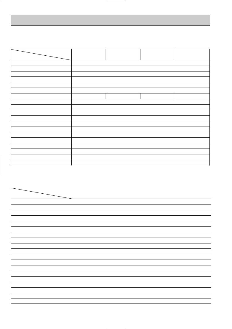
NOTE : Test conditions are based on ISO 5151
Cooling : Indoor |
D.B. 27: W.B. 19: |
Outdoor D.B. 35: W.B. 24: |
|
Heating : Indoor |
D.B. 20: W.B. 15: |
Outdoor D.B. 7: W.B. 6: Refrigerant piping length (one way): 5m
1 Measured under rated operating frequency. w Reference value
7
SEZ-KC•VA.W, SEZ-KA•VA.TH / SUZ-KA•VA(H).TH
Outdoor Service Ref.
Function
Power supply
Capacity |
Air flow 1 |
K /h |
|
Capacity Rated frequency(Min.-Max.) |
kW |
Electrical data |
Dehumidification |
r/h |
Fan motor current 1 |
A |
|
|
Starting current (Total) 1 |
A |
|
Compressor motor current 1 |
A |
Coefficient of performance(C.O.P) 1
Compressor |
resistance(at 20:) |
|
||
|
|
Model |
|
|
|
|
Output |
W |
|
|
|
Winding |
" |
|
|
|
|
||
Fan |
motor |
Model |
|
|
Winding |
" |
|||
|
|
|
||
|
|
resistance(at 20:) |
|
|
|
|
Dimensions WOHOD |
mm |
|
|
|
Weight |
kg |
|
|
|
Sound level 1 |
dB(A) |
|
|
|
Fan speed(Highw/Loww, High/Med.w/Loww) |
rpm |
|
|
|
Fan speed regulator |
|
|
Special |
remarks |
Refrigerant filling |
kg |
|
capacity(R410A) |
||||
|
|
|||
|
|
|
||
|
|
Refrigeration oil (Model) |
cc |
|
|
|
Thermistor RT61(at 0:) |
k" |
|
|
|
Thermistor RT62(at 100:) |
k" |
|
|
|
Thermistor RT64(at 50:) |
k" |
|
|
|
Thermistor RT65(at 25:) |
k" |
|
SUZ-KA25VA(H).TH |
SUZ-KA35VA(H).TH |
|||||
Indoor Service Ref. |
Indoor Service Ref. |
|||||
SEZ-KC25VA.W |
SEZ-KA35VA.TH |
|||||
Cooling |
|
|
Heating |
Cooling |
|
Heating |
|
|
|
||||
Single phase |
Single phase |
|||||
230V,50Hz |
230V,50Hz |
|||||
2.5(0.9-3.2) |
|
3.0(0.9-4.5) |
3.5(1.0-3.9) |
4.0(0.9-5.0) |
||
1.0 |
|
|
— |
1.2 |
|
— |
2,058 |
|
|
1,938 |
|
2,004 |
|
|
3.65 |
|
4.75 |
|||
2.74 |
|
|
3.37 |
4.22 |
|
4.42 |
0.31 |
|
|
0.28 |
0.33 |
|
0.33 |
3.42 |
|
|
3.61 |
3.30 |
|
3.64 |
KNB073FDVH |
KNB092FCAH |
|||||
|
550 |
|
650 |
|||
U-V 1.53 |
|
|
U-W 1.53 |
U-V 0.49 |
|
U-W 0.49 |
V-W 1.53 |
V-W 0.49 |
|||||
RC0J50-AL |
RC0J50-AL |
|||||
WHT-BLK 37.5 |
WHT-BLK 37.5 |
|||||
BLK-RED 37.5 |
BLK-RED 37.5 |
|||||
RED-WHT 37.5 |
RED-WHT 37.5 |
|||||
800o550o285 |
800o550o285 |
|||||
|
33 |
|
37 |
|||
|
46 |
47 |
|
48 |
||
810w/650w |
|
880w/810w/650w |
840w/760w |
880w/800w/630w |
||
|
||||||
2 |
|
|
3 |
2 |
|
3 |
|
0.90 |
|
1.05 |
|||
320 (NEO22) |
320 (NEO22) |
|||||
|
32.6 |
|
32.6 |
|||
|
13.4 |
|
13.4 |
|||
|
17 |
|
17 |
|||
|
10 |
|
10 |
|||
|
|
|
|
|
|
|
NOTE : Test conditions are based on ISO 5151
Cooling : Indoor |
Dry-bulb temperature 27:Wet-bulb temperature 19: |
Outdoor |
Dry-bulb temperature 35:Wet-bulb temperature(24:) |
Heating : Indoor |
Dry-bulb temperature 20:Wet-bulb temperature 15: |
Outdoor Dry-bulb temperature 7: Wet-bulb temperature 6: Refrigerant piping length (one way): 5m
1 Measured under rated operating frequency w Reference value
8

SEZ-KA•VA.TH / SUZ-KA•VA.TH
|
|
|
|
|
|
SUZ-KA50VA.TH |
SUZ-KA60VA.TH |
SUZ-KA71VA.TH |
||||||
|
|
|
Outdoor Service Ref. |
|
Indoor Service Ref. |
Indoor Service Ref. |
Indoor Service Ref. |
|||||||
|
|
|
|
|
|
SEZ-KA50VA.TH |
SEZ-KA60VA.TH |
SEZ-KA71VA.TH |
||||||
|
|
|
|
|
|
|
|
|
|
|
|
|
|
|
|
|
|
Function |
|
Cooling |
Heating |
Cooling |
Heating |
Cooling |
|
Heating |
|||
|
|
|
Power supply |
|
Single phase |
Single phase |
Single phase |
|||||||
|
|
|
|
230V,50Hz |
230V,50Hz |
230V,50Hz |
||||||||
|
|
|
|
|
|
|||||||||
|
|
|
Capacity Rated frequency(Min.~Max.) |
kW |
5.0(1.1-5.6) 5.9(1.1-7.2) |
5.5(1.1-6.3) 6.9(0.9-8.0) |
7.1(0.9-8.3) |
8.1(0.9-10.4) |
|
|||||
Capacity |
Dehumidification |
|
r/h |
1.9 |
— |
2.0 |
|
— |
2.7 |
|
— |
|||
Air flow(High/Loww) |
K /h |
2,940/1,650w 2,940/2,210w |
2,940/1,650w 2,940/2,210w |
2,940/1,650w |
2,940/2,210w |
|
||||||||
Electrical |
data |
Fan motor current |
A |
|
0.30 |
0.30 |
|
0.30 |
|
|
||||
|
|
|
Starting current |
1 |
A |
|
6.75 |
9.75 |
|
10.30 |
|
|||
|
|
|
Compressor motor current 1 |
A |
6.45 |
6.05 |
8.05 |
|
9.45 |
10.00 |
|
9.60 |
|
|
|
|
|
|
|
|
|
|
|
|
|
||||
Coefficient of performance(C.O.P) |
2.81 |
3.21 |
2.81 |
|
2.82 |
2.89 |
|
3.43 |
|
|||||
Compressor |
resistance(at 20:) |
|
V-W 0.45 |
V-W 0.45 |
V-W 1.41 |
|||||||||
|
|
|
Model |
|
|
SNB130FLDH |
SNB130FLDH |
TNB220FMCH |
||||||
|
|
|
Output |
|
W |
|
850 |
850 |
|
1300 |
|
|
||
|
|
|
Winding |
|
" |
U-V 0.45 |
U-W 0.45 |
U-V 0.45 |
U-W 0.45 |
U-V 1.41 |
U-W 1.41 |
|||
|
|
|
|
|
|
|
|
|
|
|
|
|
|
|
|
|
|
|
|
|
|
|
|
|
|
||||
|
motor |
Model |
|
|
RC0J60-AA |
RC0J60-AA |
RC0J60-AA |
|||||||
Fan |
Winding |
|
|
BLK-WHT 15.2 |
BLK-WHT 15.2 |
BLK-WHT 15.2 |
||||||||
|
|
|
|
|
||||||||||
|
|
|
|
" |
WHT-RED 15.2 |
WHT-RED 15.2 |
WHT-RED 15.2 |
|||||||
|
|
|
resistance(at 20:) |
|||||||||||
|
|
|
|
RED-BLK 15.2 |
RED-BLK 15.2 |
RED-BLK 15.2 |
||||||||
|
|
|
|
|
|
|||||||||
|
|
|
Dimensions WOHOD |
mm |
840o850o330 |
840o850o330 |
840o850o330 |
|||||||
|
|
|
Weight |
|
kg |
|
53 |
53 |
|
58 |
|
|
||
|
|
|
Sound level(High/Loww) |
dB |
53/51w |
55/53w |
53/51w |
55/53w |
53/51w |
|
55/53w |
|||
|
|
|
Fan speed(High/Loww) |
rpm |
800/480w |
800/620w |
800/480w |
800/620w |
800/480w |
|
800/620w |
|||
|
|
|
Fan speed regulator |
|
|
2 |
2 |
|
2 |
|
|
|||
|
remarks |
Refrigerant filling |
|
kg |
|
1.60 |
1.80 |
|
2.00 |
|
|
|||
Special |
capacity(R410A) |
|
|
|
|
|
||||||||
|
|
|
|
|
|
|
|
|
|
|
||||
|
|
|
|
|
|
|
|
|
|
|
|
|
|
|
|
|
|
Refrigerating oil (Model) |
cc |
450 (NEO22) |
450 (NEO22) |
870 (NEO22) |
|||||||
|
|
|
Thermistor RT61 (at 25:) |
k" |
|
10.0 |
10.0 |
|
10.0 |
|
|
|||
|
|
|
Thermistor RT62 (at 100:) |
k" |
|
13.4 |
13.4 |
|
13.4 |
|
|
|||
|
|
|
Thermistor RT64 (at 50:) |
k" |
|
17.0 |
17.0 |
|
17.0 |
|
|
|||
|
|
|
Thermistor RT65 (at 25:) |
k" |
|
10.0 |
10.0 |
|
10.0 |
|
|
|||
|
|
|
Thermistor RT68 (at 25:) |
k" |
|
10.0 |
10.0 |
|
10.0 |
|
|
|||
NOTE : Test conditions are based on ISO 5151 |
|
|
|
|
|
|
|
|
||||||
|
|
|
Cooling : Indoor |
D.B. 27: W.B. 19: |
|
|
|
|
|
|
|
|
||
|
|
|
Outdoor D.B. 35: W.B. 24: |
|
|
|
|
|
|
|
|
|||
|
|
|
Heating : Indoor |
D.B. 20: W.B. 15: |
|
|
|
|
|
|
|
|
||
|
|
|
Outdoor D.B. 7: W.B. 6: |
|
|
|
|
|
|
|
|
|||
Refrigerant piping length (one way): 5m
1 Measured under rated operating frequency. w Reference value
9
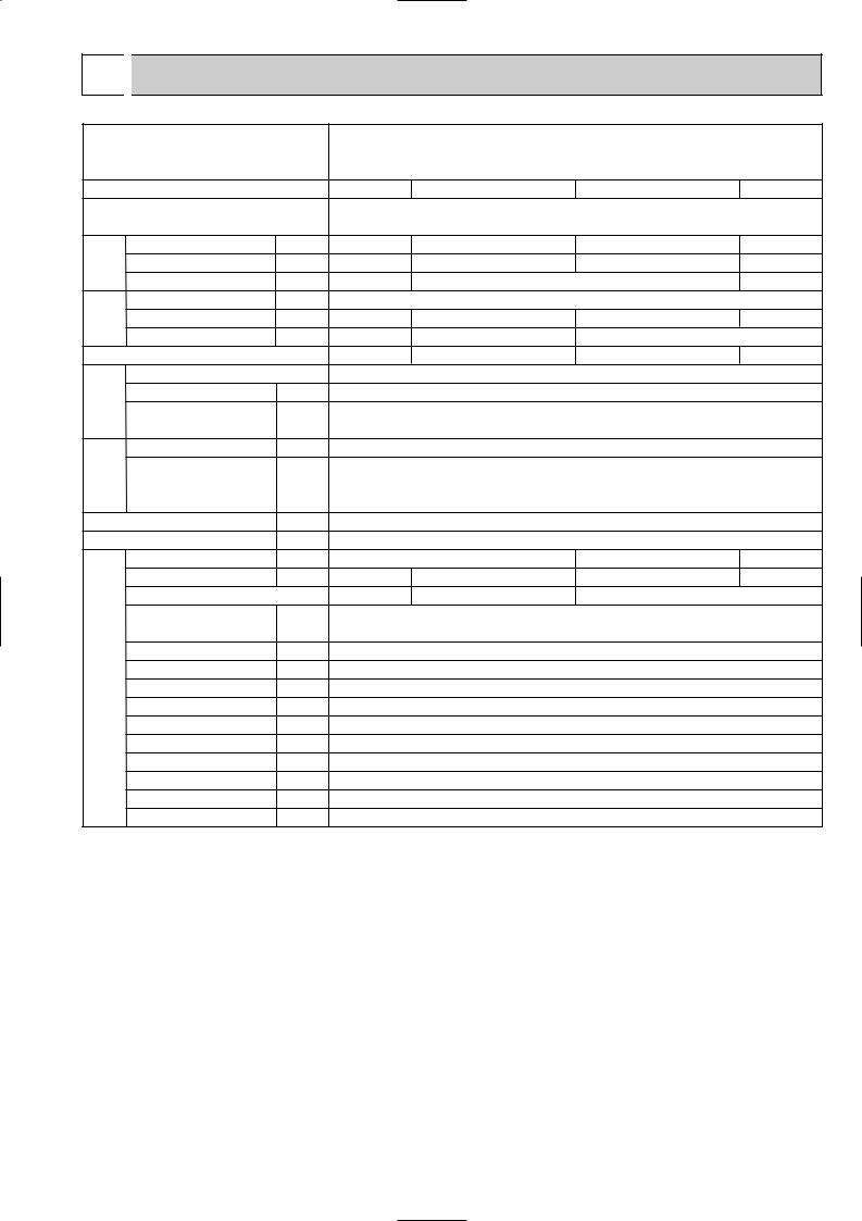
Specifications and rating conditions of main electric parts
SUZ-KA25VA.TH SUZ-KA25VAH.TH
SUZ-KA35VA.TH SUZ-KA35VAH.TH
Item |
Model |
|
|
Current transformer |
(CT) |
Current transformer |
(CT761, CT781) |
Smoothing capacitor (C63A, C63B, C63C)
Diode module |
(DB61, DB65) |
|
Fuse |
|
(F61) |
Fuse |
(F71, F801, F901) |
|
Defrost heater |
|
(H) |
Intelligent power module |
(IPM) |
|
Expansion valve coil |
(LEV) |
|
Reactor |
|
(L61) |
Current-detecting resistor |
(R61) |
|
Current-detecting resistor |
(R831) |
|
Current-limiting resistor (R64A, R64B)
Terminal block |
(TB1,TB2) |
Relay |
(X63) |
Relay |
(X64) |
Relay |
(X66) |
R.V. coil |
(21S4) |
Heater protector |
(26H) |
SUZ-KA25VA.TH SUZ-KA25VAH.TH SUZ-KA35VA.TH SUZ-KA35VAH.TH
ETA19Z59BZ
ETQ19Z71AY 620+ 420V D25XB60 250V 20A 250V 3.15A
— 230V 130W — 230V 130W PS21244-A-203
CAD-MD12ME 12VDC 10A 23.0mH
|
45m" 5W (1 element) |
|
50m" 5W (2 elements) |
|||
|
|
25m" 5W |
|
|
|
|
|
|
5.1" 5W |
|
|
|
|
|
|
3P |
|
|
|
|
|
|
G5NB-1a |
|
|
|
|
|
|
G4A-1A-PS |
|
|
|
|
— |
|
G5NB-1a |
|
— |
|
G5NB-1a |
|
|
|
||||
|
|
STF-01AJ503 |
|
|
|
|
— |
|
Open 45: |
|
— |
|
Open 45: |
|
|
|
||||
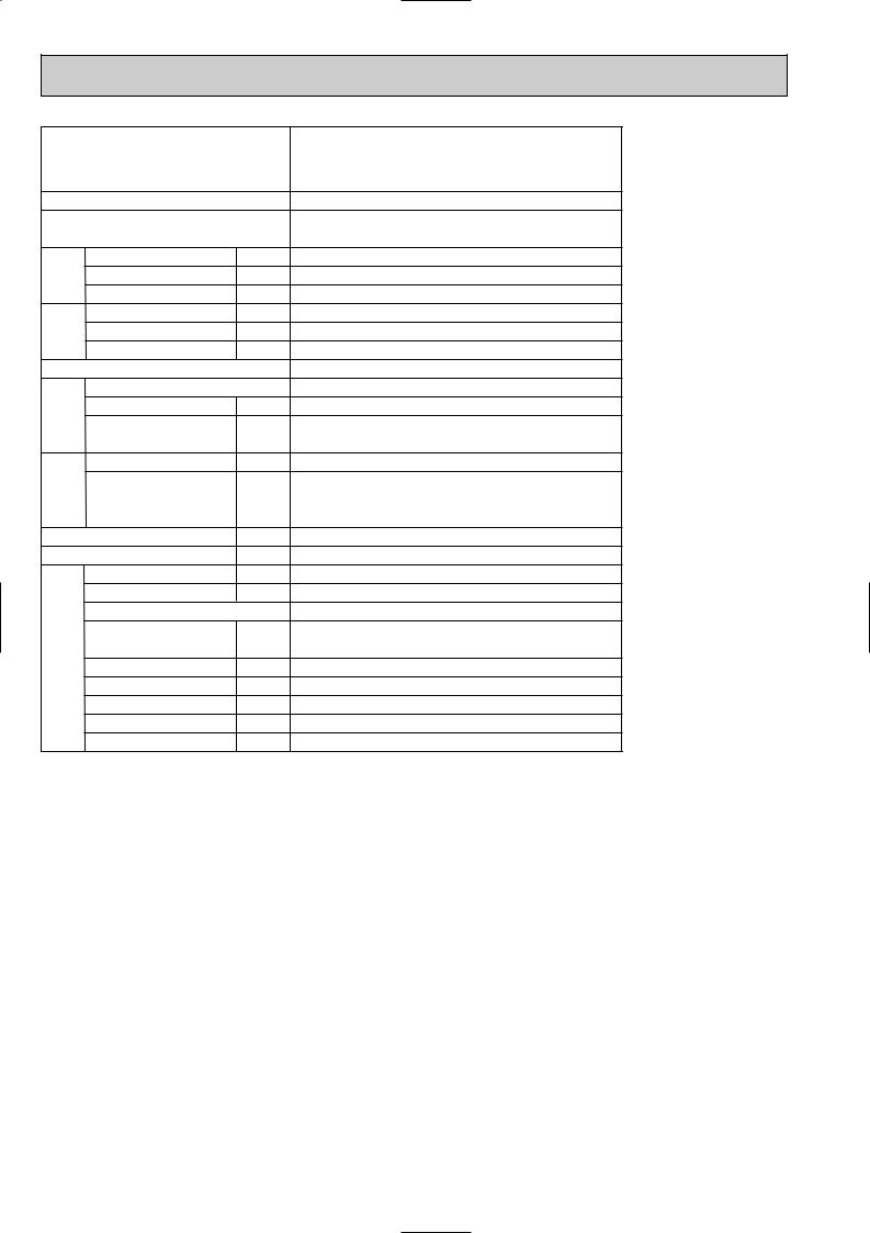
SUZ-KA50VA.TH
SUZ-KA60VA.TH
SUZ-KA71VA.TH
Item |
Model |
SUZ-KA50VA.TH |
|
SUZ-KA60VA.TH |
|
SUZ-KA71VA.TH |
|
|
|
||||
|
|
|
|
|
|
|
Smoothing capacitor |
(CB1,2,3) |
|
|
560+ 450V |
|
|
|
|
|
|
|||
Current transformer |
(CT1,2) |
|
|
ETQ19Z68AY |
|
|
Current transformer |
(CT61) |
|
|
ETQ19Z53AY |
|
|
Fuse |
(F64) |
|
|
250V 2A |
|
|
Fuse |
(F801) |
|
|
250V 3.15A |
|
|
Fuse |
(F911) |
|
|
250V 1A |
|
|
Intelligent power module |
(HC930) |
|
|
PS21661-RZ |
|
|
High pressure switch |
(HPS) |
— |
|
|
ACB-DB156 |
|
|
|
|||||
Intelligent power module |
(IPM) |
|
|
PS21244-A |
|
|
Reactor |
(L) |
|
|
340 H 20A |
|
|
Expansion valve coil |
(LEV) |
|
|
CAM-MD12ME |
|
|
Power factor controller |
(PFC) |
|
|
PS51259-A |
|
|
Resistor |
(R64A,B) |
|
|
10" 10W |
|
|
Resistor |
(R937A,B) |
|
|
1.1" 2W 2% |
|
|
Resistor |
(RS1~4) |
|
|
0.04" 7W |
|
|
Solenoid coil relay |
(SSR61) |
|
|
TLP3506 |
|
|
Terminal block |
(TB1) |
|
|
3P |
|
|
Terminal block |
(TB2) |
|
|
3P |
|
|
Relay |
(X64) |
|
|
G4A |
|
|
R.V. coil |
(21S4) |
|
|
LD30013 |
|
|
10

5 NOISE CRITERIA CURVES
SUZ-KA25VA.TH
SUZ-KA25VAH.TH
FAN SPEED |
FUNCTION |
SPL(dB(A)) |
LINE |
High |
COOLING |
46 |
|
Med. |
HEATING |
46 |
|
|
|
Test conditions,
|
|
Cooling : Dry-bulb temperature 35: Wet-bulb temperature (24:) |
||||||||
|
90 |
Heating : Dry-bulb temperature |
7: Wet-bulb temperature |
6: |
||||||
BAR |
|
|
|
|
|
|
|
|
|
|
|
|
|
|
|
|
|
|
|
|
|
MICRO |
80 |
|
|
|
|
|
|
|
|
|
|
|
|
|
|
|
|
|
|
|
|
0.0002 |
70 |
|
|
|
|
|
|
|
|
NC-70 |
|
|
|
|
|
|
|
|
|
||
dB re |
60 |
|
|
|
|
|
|
|
|
|
LEVEL, |
|
|
|
|
|
|
|
|
|
|
|
|
|
|
|
|
|
|
|
NC-60 |
|
50 |
|
|
|
|
|
|
|
|
|
|
PRESSURE |
|
|
|
|
|
|
|
|
|
|
|
|
|
|
|
|
|
|
|
NC-50 |
|
40 |
|
|
|
|
|
|
|
|
|
|
|
|
|
|
|
|
|
|
|
NC-40 |
|
SOUND |
|
|
|
|
|
|
|
|
|
|
30 |
|
|
|
|
|
|
|
|
|
|
BAND |
|
|
|
|
|
|
|
|
|
NC-30 |
20 |
APPROXIMATE |
|
|
|
|
|
|
|
||
OCTAVE |
|
|
|
|
|
|
|
|||
THRESHOLD OF |
|
|
|
|
|
|
|
|||
|
|
|
|
|
|
|
|
|||
|
HEARING FOR |
|
|
|
|
|
|
NC-20 |
||
|
CONTINUOUS |
|
|
|
|
|
|
|
||
10 |
NOISE |
|
|
|
|
|
|
|
|
|
|
63 |
125 |
250 |
500 |
1000 |
2000 |
4000 |
8000 |
||
|
|
|||||||||
BAND CENTER FREQUENCIES, Hz
SUZ-KA35VA.TH
SUZ-KA35VAH.TH
FAN SPEED |
FUNCTION |
SPL(dB(A)) |
LINE |
High |
COOLING |
47 |
|
Med. |
HEATING |
48 |
|
|
|
Test conditions,
|
|
Cooling : Dry-bulb temperature 35: Wet-bulb temperature (24:) |
||||||||
|
90 |
Heating : Dry-bulb temperature |
7: Wet-bulb temperature |
6: |
||||||
BAR |
|
|
|
|
|
|
|
|
|
|
|
|
|
|
|
|
|
|
|
|
|
MICRO |
80 |
|
|
|
|
|
|
|
|
|
|
|
|
|
|
|
|
|
|
|
|
0.0002 |
70 |
|
|
|
|
|
|
|
|
NC-70 |
|
|
|
|
|
|
|
|
|
||
dB re |
60 |
|
|
|
|
|
|
|
|
|
LEVEL, |
|
|
|
|
|
|
|
|
|
|
|
|
|
|
|
|
|
|
|
NC-60 |
|
50 |
|
|
|
|
|
|
|
|
|
|
PRESSURE |
|
|
|
|
|
|
|
|
|
|
|
|
|
|
|
|
|
|
|
NC-50 |
|
40 |
|
|
|
|
|
|
|
|
|
|
|
|
|
|
|
|
|
|
|
NC-40 |
|
SOUND |
|
|
|
|
|
|
|
|
|
|
30 |
|
|
|
|
|
|
|
|
|
|
BAND |
|
|
|
|
|
|
|
|
|
NC-30 |
20 |
APPROXIMATE |
|
|
|
|
|
|
|
||
OCTAVE |
|
|
|
|
|
|
|
|||
THRESHOLD OF |
|
|
|
|
|
|
|
|||
|
|
|
|
|
|
|
|
|||
|
HEARING FOR |
|
|
|
|
|
|
NC-20 |
||
|
CONTINUOUS |
|
|
|
|
|
|
|
||
10 |
NOISE |
|
|
|
|
|
|
|
|
|
|
63 |
125 |
250 |
500 |
1000 |
2000 |
4000 |
8000 |
||
|
|
|||||||||
BAND CENTER FREQUENCIES, Hz
SUZ-KA50VA.TH
SUZ-KA60VA.TH
SUZ-KA71VA.TH
FAN SPEED FUNCTION SPL(dB(A)) |
LINE |
COOLING 53
High
HEATING 55
OUTDOORUNIT
1m
MICROPHONE
Test conditions,
|
|
Cooling : Dry-bulb temperature 35: Wet-bulb temperature (24:) |
|||||||
|
90 |
Heating : Dry-bulb temperature |
7: Wet-bulb temperature 6: |
||||||
BAR |
|
|
|
|
|
|
|
|
|
|
|
|
|
|
|
|
|
|
|
MICRO |
80 |
|
|
|
|
|
|
|
|
|
|
|
|
|
|
|
|
|
|
0.0002 |
70 |
|
|
|
|
|
|
|
NC-70 |
|
|
|
|
|
|
|
|
||
dB re |
60 |
|
|
|
|
|
|
|
|
LEVEL, |
|
|
|
|
|
|
|
|
|
|
|
|
|
|
|
|
|
NC-60 |
|
50 |
|
|
|
|
|
|
|
|
|
PRESSURE |
|
|
|
|
|
|
|
|
|
|
|
|
|
|
|
|
|
NC-50 |
|
40 |
|
|
|
|
|
|
|
|
|
|
|
|
|
|
|
|
|
NC-40 |
|
SOUND |
|
|
|
|
|
|
|
|
|
30 |
|
|
|
|
|
|
|
|
|
BAND |
|
|
|
|
|
|
|
|
NC-30 |
20 |
APPROXIMATE |
|
|
|
|
|
|
||
OCTAVE |
|
|
|
|
|
|
|||
THRESHOLD OF |
|
|
|
|
|
|
|||
|
|
|
|
|
|
|
|||
|
HEARING FOR |
|
|
|
|
|
NC-20 |
||
|
CONTINUOUS |
|
|
|
|
|
|
||
10 |
NOISE |
|
|
|
|
|
|
|
|
|
63 |
125 |
250 |
500 |
1000 |
2000 |
4000 |
8000 |
|
|
|
||||||||
BAND CENTER FREQUENCIES, Hz
11
6 
 OUTLINES AND DIMENSIONS
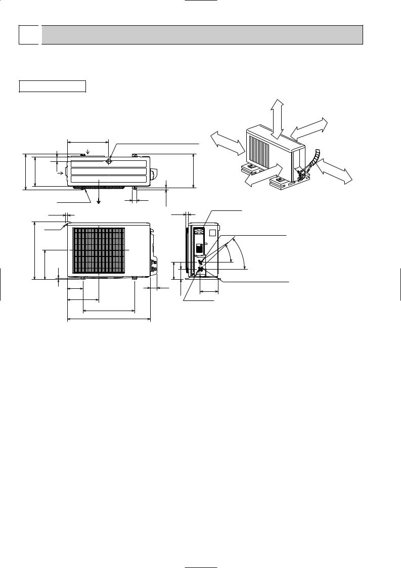
SUZ-KA25VA.TH SUZ-KA25VAH.TH SUZ-KA35VA.TH SUZ-KA35VAH.TH
OUTDOOR UNIT
Unit: mm
344.5 |
285 |
Air
44 in
REQUIRED SPACE
Basically open 100mm or more without any obstruction in front and on both sides of the unit.
Drain hole [42 (SUZ-KA25/KA35VA)
Drain hole [33 (SUZ-KA25/KA35VAH)
400 Air in
Bolt pitch for installation 304~325
100mm |
or |
|
more |
or |
more |
|
200mm
or |
more |
|
100mm
350mm |
or |
|
more |
2 holes 10X21 |
40 |
17.5 |
|
||
|
|
|
22.3 |
Air out |
23 |
|
Handle
550
280 |
10 |
|
164.5 |
|
150 |
69 |
99.5 |
|
|
302.5 |
|
|
|
|
500 Bolt pitch for installation
800
Open two sides of left, right, or rear side.
Service panel
Liquid refrigerant pipe joint
Refrigerant pipe (flared) [6.35
- |
- |
35 |
43 |
Gas refrigerant pipe joint
Refrigerant pipe (flared) [9.52
170.5
Service port
12
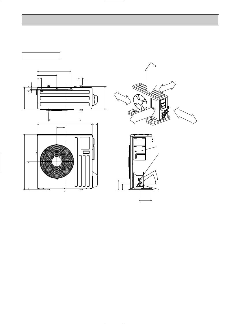
SUZ-KA50VA.TH
SUZ-KA60VA.TH
SUZ-KA71VA.TH
OUTDOOR UNIT |
REQUIRED SPACE |
|
|
515 |
|
|
299 |
40 |
|
66 |
|
51 |
34 |
100mm or more |
|
|
|
330 |
|
360 |
500
Unit: mm
Open as a rule 500mm or more if the front and both sides are open
100mm or more 200mm or more if there are obstacles to both sides
850
430
840
121
80 Open as a rule
500mm or more if the back, 350mm or more both sides and top are open
|
Service panel |
|
Liquid refrigerant |
|
pipe joint |
|
Refrigerant pipe(flared) |
|
[6.35·····(SUZ-KA50/KA60VA.TH) |
|
[9.52·····(SUZ-KA71VA.TH) |
|
- |
|
30 |
|
- |
155 90 |
35 |
Gas refrigerant |
|
|
pipe joint |
198 |
Refrigerant pipe(flared) |
[12.7·····(SUZ-KA50VA.TH) |
[15.88···(SUZ-KA60/KA71VA.TH)
13
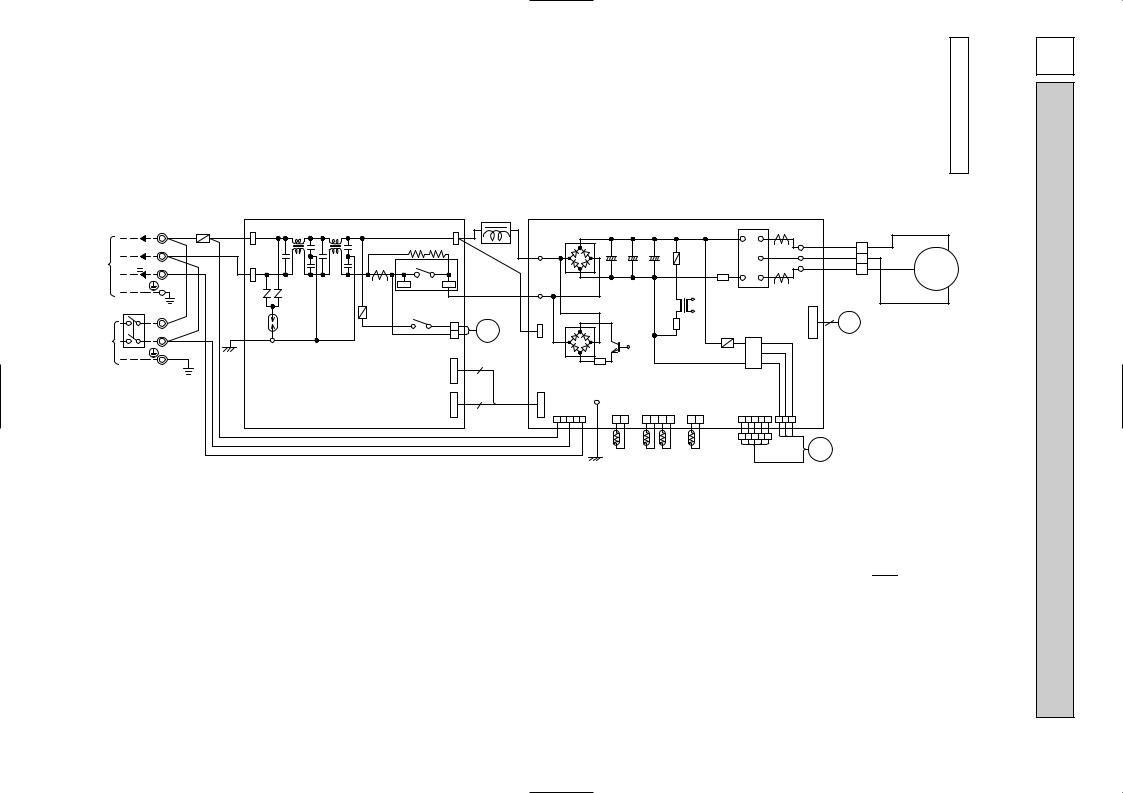
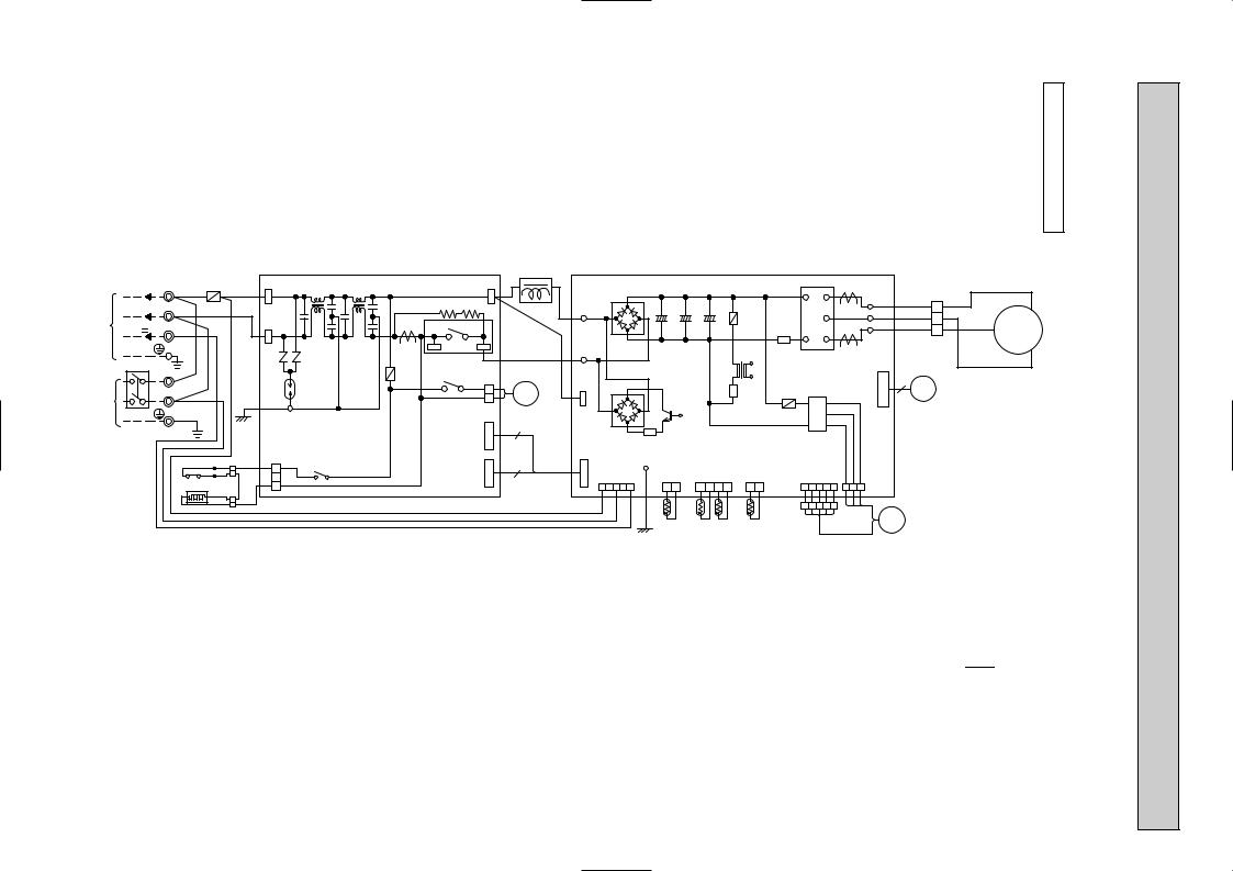
UNIT OUTDOOR |
TH.KA25VA-SUZ TH.KA35VA-SUZ |
|
|
230V~ |
TB2 |
F61 |
WHT |
TAB61 |
L62 |
L63 |
|
TAB63 BLK |
L61 |
BLK |
|
|
|
|
|
|
|
|
|
|
|
|
BLK |
|
|
||
INDDORTO UNIT |
CONNECTING |
S1 |
WHT |
|
NR64 |
|
|
BLU |
BLK |
|
|
|
T801 |
IPM |
|
|
|
|
|
|
V |
MODELS |
|||||||
|
|
|
|
|
NR63 |
|
|
|
|
|
|
|
|
|
|
|
|
|
|||||||||||
|
|
|
|
|
|
|
|
|
|
R64B R64A |
|
|
DB61 |
|
|
|
|
|
U |
|
LD-U |
BLK |
|
|
|
|
U |
|
|
|
|
|
S2 |
BLU |
|
|
|
|
|
|
|
|
|
|
|
+ |
+ |
+ |
|
P |
CT761 |
LD-V |
WHT |
1 |
W |
|
|
|
|
|
|
12-24V |
S3 |
RED |
|
|
TAB62 |
|
|
|
X64 |
|
|
LD70 |
|
C63A |
C63B |
C63C |
F801 |
V |
|
2 |
wc |
|
|
||||
|
|
|
|
|
|
|
|
|
|
|
|
N |
|
LD-W |
RED |
3 |
RED |
|
|
|
|||||||||
|
|
|
|
|
|
|
|
|
|
4 |
3 |
|
|
|
|
|
|
|
|
W |
|
CN61 |
|
|
|
|
|
||
|
|
|
|
|
|
|
|
|
CT |
|
|
|
|
|
|
|
|
|
|
|
|
|
|
|
|||||
|
|
|
|
|
|
|
|
|
|
|
|
|
|
|
|
|
R61 |
CT781 |
|
|
|
|
|
|
|
|
|||
|
|
|
|
|
|
|
|
|
|
|
|
|
|
|
|
|
|
|
|
|
|
|
|
WHT |
|
|
|||
|
CIRCUIT BREAKER |
|
|
|
|
|
|
|
|
|
|
LD69 |
|
|
|
|
|
|
|
CN724 |
|
|
|
|
WIRING |
||||
|
TB1 |
|
|
|
|
F71 |
X63 |
|
|
|
|
|
|
|
|
|
|
6 |
|
|
|
|
|
||||||
|
|
|
|
|
|
|
TB800 |
|
|
|
|
|
|
|
|
|
|
|
|
|
|||||||||
|
|
|
L |
|
|
|
|
DSA61 |
|
|
1 |
|
|
|
|
|
|
IC801 |
|
|
|
LEV |
|
|
|
|
|
|
|
|
|
|
|
|
|
|
|
|
|
21S4 |
|
|
|
|
|
|
|
|
|
|
|
|
|
|
|||||
|
|
|
|
|
|
GRN |
|
|
|
|
|
|
|
|
|
|
F901 |
|
|
|
|
|
|
|
|
|
|||
~/N |
|
|
N |
|
|
|
|
|
|
2 |
|
|
TR821 |
|
|
|
|
|
|
|
|
|
|
|
|
||||
|
|
|
|
|
|
|
|
|
|
|
|
|
|
|
|
|
|
|
|
|
|
|
|
|
|||||
230V 50Hz |
|
|
GRN/YLW |
|
LDE |
|
|
CN721 |
|
|
|
|
|
|
|
|
|
|
|
|
|
|
|
|
|
|
|||
POWER |
|
|
|
|
|
|
|
CN727 |
6 |
|
DB65 |
|
|
|
|
|
|
|
|
|
|
|
|
|
|
|
|||
|
|
PE |
|
|
|
|
|
|
|
|
R831 |
|
|
|
|
|
|
|
|
|
|
|
|
|
DIAGRAM |
||||
14 |
|
|
|
|
BLU |
|
|
|
|
|
|
|
|
|
|
|
|
IC932 |
|
|
|
|
|
|
|
|
|||
|
|
|
|
|
|
|
|
|
|
|
|
|
GRN |
|
|
|
|
|
|
|
|
|
|
|
|
||||
SUPPLY |
|
|
|
|
|
|
|
|
|
|
|
|
|
|
|
|
|
|
|
|
|
|
|
|
|
|
|
||
|
|
|
|
|
|
|
|
|
|
|
CN726 |
4 |
|
CN725 |
LDY |
INVERTER P.C. BOARD |
|
|
|
|
|
|
|
|
|
||||
|
|
|
|
|
|
|
|
POWER P.C. BOARD |
|
|
|
CN601 |
|
CN643 |
CN641 |
CN642 |
CN931 |
1 2 3 CN932 |
|
|
|
|
|
|
|
||||
|
|
|
|
|
|
|
|
|
|
|
1 2 3 4 5 |
|
1 2 |
1 2 3 4 |
1 2 |
1 2 3 4 5 |
|
|
|
|
|
|
|
||||||
|
|
|
|
|
|
WHITE |
|
|
|
|
|
|
|
|
|
|
|
|
1 2 3 4 5 |
|
|
|
|
|
|
|
|
|
|
|
|
|
|
|
RED |
|
|
|
|
|
|
|
|
|
RT65 |
RT61 RT62 |
RT64 |
|
|
MF |
|
|
|
|
|
|
|||
|
|
|
|
|
|
|
|
|
|
|
|
|
|
|
|
|
|
|
|
|
|
|
|
|
|
||||
SYMBOL |
NAME |
SYMBOL |
NAME |
SYMBOL |
NAME |
|
|
|
|
|
|
CT,CT761,CT781 |
CURRENT TRANSFORMER |
L61 |
REACTOR |
R61,R831 |
CURRENT-DETECTING RESISTOR |
|
|
|
|
|
|
C63A,C63B,C63C |
SMOOTHING CAPACITOR |
L62,L63 |
CMC COIL |
R64A,R64B |
CURRENT-LIMITING RESISTOR |
|
|
|
|
|
|
DB61,DB65 |
DIODE MODULE |
MC |
COMPRESSOR |
TB1,TB2 |
TERMINAL BLOCK |
|
|
|
|
|
|
DSA61 |
SURGE ABSORBER |
MF |
OUTDOOR FAN MOTOR |
TR821 |
SWITCHING POWER TRANSISTOR |
|
|
|
|
|
|
F61 |
FUSE (T20AL250V) |
NR63,NR64 |
VARISTOR |
T801 |
TRANSFORMER |
|
|
|
|
|
|
F71 |
FUSE (T3.15AL250V) |
RT61 |
DEFROST THERMISTOR |
X63,X64 |
RELAY |
|
|
|
|
|
|
F801,F901 |
FUSE (T3.15AL250V) |
RT62 |
DISCHARGE TEMPERATURE THERMISTOR |
21S4 |
R.V. COIL |
|
|
|
|
|
|
IC801 |
INTELLIGENT POWER DEVICE |
RT64 |
FIN TEMPERATURE THERMISTOR |
LEV |
EXPANSION VALVE COIL |
|
|
|
|
|
|
IPM,IC932 |
INTELLIGENT POWER MODULE |
RT65 |
AMBIENT TEMPERATURE THERMISTOR |
|
|
|
|
|
|
|
|
NOTE:1. About the indoor side electric wiring refer to the indoor unit electric wiring diagram for servicing.
2.Use copper conductors only. (For field wiring) 3. Symbols below indicate.
/: Terminal block,  : Connector
DIAGRAM WIRING 7
15
UNITINDDORTO CONNECTING |
|
|
|
|
|
|
|
|
|
|
|
|
|
|
|
|
|
|
|
|
|
|
|
|
|
|
|
UNIT OUTDOOR |
TH.KA35VAH-SUZ |
TH.KA25VAH-SUZ |
|
|
|
F61 |
|
|
|
|
|
CT |
4 |
3 |
L61 |
BLK |
|
|
|
|
|
R61 |
CT781 |
|
|
|
|
|
|
|
MODELS |
||
|
230V~ |
TB2 |
WHT |
|
WHT |
TAB61 |
L62 |
L63 |
|
|
TAB63 BLK |
|
|
|
|
|
|
|
|
|
|
|
BLK |
|
|
|
||||
|
S1 |
|
|
|
|
|
|
|
|
DB61 |
|
|
|
|
|
U |
|
LD-U |
BLK |
|
|
U |
|
|
||||||
|
|
|
|
|
|
|
|
|
|
|
|
R64B |
R64A |
|
|
|
|
|
|
|
|
|
|
|
|
|||||
|
|
S2 |
BLU |
|
|
|
|
|
|
|
|
|
|
|
+ |
+ |
+ |
|
P |
CT761 |
1 |
|
|
|
|
|||||
|
|
|
|
|
|
|
|
|
|
|
|
|
|
|
|
LD-V |
WHT |
|
W |
|
|
|
||||||||
|
|
|
|
|
|
TAB62 |
|
|
|
|
|
|
|
|
F801 |
V |
2 |
RED |
|
|
|
|||||||||
|
12-24V |
S3 |
RED |
|
|
|
|
|
|
|
X64 |
|
LD70 |
|
C63A |
C63B |
C63C |
|
|
RED |
|
|
|
|||||||
230V 50Hz |
|
|
|
|
|
DSA61 |
|
|
21S4 |
|
IC801 |
N |
|
LD-W |
3 |
MC |
|
|
WIRING |
|||||||||||
|
|
|
|
|
|
|
|
|
|
|
1 |
BLK |
|
|
|
|
F901 |
|
LEV |
|
|
|
|
|||||||
|
|
|
|
|
|
|
|
|
|
|
|
|
|
BLU |
|
|
|
|
|
|
W |
|
|
|
CN61 |
|
|
|
|
|
CIRCUIT BREAKER |
TB1 |
|
|
|
|
|
NR64 |
NR63 |
|
F71 |
|
|
|
LD69 |
|
|
|
|
T801 |
IPM |
|
CN724 |
|
|
|
WHT |
V |
|
|
|
|
|
|
|
|
|
|
|
X63 |
|
|
|
|
|
|
|
|
|
|
|
|
|
|
|
|
||||||
~/N |
|
L |
|
|
|
|
|
|
|
|
|
|
TB800 |
|
|
|
|
|
|
|
|
6 |
|
|
|
|
|
|
||
|
|
|
|
|
|
|
|
|
|
|
|
|
|
|
|
|
|
|
|
|
|
|
|
|
|
|||||
|
N |
|
|
|
|
|
|
|
|
|
|
|
|
|
|
|
|
|
|
|
|
|
|
|
|
|
|
|||
|
|
|
|
|
|
GRN |
|
|
|
|
|
2 |
|
|
|
TR821 |
|
|
|
|
|
|
|
|
|
|
|
DIAGRAM |
||
POWER |
|
|
GRN/YLW |
|
|
2 |
|
|
|
|
CN721 |
|
CN601 |
|
|
CN642 |
CN931 |
|
|
|
|
|
|
|
|
|||||
|
|
|
|
|
|
|
|
|
|
|
CN643 |
CN641 |
|
|
|
|
|
|
|
|
||||||||||
SUPPLY |
|
|
|
|
|
|
|
|
|
|
|
|
|
6 |
|
|
|
|
|
|
|
|
|
|
|
|
|
|
|
|
|
|
PE |
|
|
|
|
POWER P.C. BOARD |
|
|
|
|
DB65 |
R831 |
|
|
|
IC932 |
|
|
|
|
|
|
|
|
|
||||
|
|
|
|
|
|
|
|
CN722 |
|
|
|
|
CN726 |
|
CN725 |
LDY |
INVERTER P.C. BOARD |
|
|
|
|
|
|
|
|
|
|
|||
|
|
|
|
BLK |
BLK |
|
RED |
X66 |
|
|
|
|
4 |
|
|
|
|
|
|
|
|
|
|
|
|
|
|
|
||
|
|
|
|
1 |
1 |
|
|
|
|
|
|
|
|
|
|
|
|
|
|
|
|
|
|
|
|
|||||
|
|
|
26H |
BLK |
BLK |
2 |
|
|
|
|
|
|
|
|
|
|
|
|
|
|
|
|
|
|
|
|
|
|
|
|
|
|
|
|
|
|
YLW |
3 |
|
|
|
|
|
|
1 2 3 4 5 |
|
1 2 |
1 2 3 4 |
1 2 |
1 2 3 4 5 |
1 2 3 CN932 |
|
|
|
|
|
|
|
|||
|
|
|
H |
|
BLK |
|
|
|
|
|
|
|
|
|
|
|
|
|
|
|
|
|||||||||
|
|
|
|
|
BLK |
1 |
BLK |
|
|
|
|
|
|
|
|
GRN |
|
|
|
|
|
|
|
|
|
|
|
|
|
|
|
|
|
|
|
|
2 |
|
|
WHITE |
|
|
|
|
|
|
|
|
|
|
1 2 3 4 5 |
|
|
|
|
|
|
|
|
|
|
|
|
|
|
|
|
|
|
|
|
|
|
|
|
|
|
|
|
|
|
|
|
|
|
|
|
|
|
|||
|
|
|
|
|
|
|
|
RED |
BLU |
|
|
|
|
|
|
|
RT65 |
RT61 RT62 |
RT64 |
|
|
MF |
|
|
|
|
|
|
||
|
|
|
|
|
|
|
|
|
|
|
|
|
|
|
|
|
|
|
|
|
|
|
|
|
|
|||||
SYMBOL |
NAME |
SYMBOL |
NAME |
SYMBOL |
NAME |
|
|
|
|
|
|
CT,CT761,CT781 |
CURRENT TRANSFORMER |
L61 |
REACTOR |
R64A,R64B |
CURRENT-LIMITING RESISTOR |
|
|
|
|
|
|
C63A,C63B,C63C |
SMOOTHING CAPACITOR |
L62,L63 |
CMC COIL |
TB1,TB2 |
TERMINAL BLOCK |
|
|
|
|
|
|
DB61,DB65 |
DIODE MODULE |
MC |
COMPRESSOR |
TR821 |
SWITCHING POWER TRANSISTOR |
DSA61 |
SURGE ABSORBER |
MF |
OUTDOOR FAN MOTOR |
T801 |
TRANSFORMER |
|
|
|
|
|
|
F61 |
FUSE (T20AL250V) |
NR63,NR64 |
VARISTOR |
X63,X64,X66 |
RELAY |
|
|
|
|
|
|
F71 |
FUSE (T3.15AL250V) |
RT61 |
DEFROST THERMISTOR |
21S4 |
R.V. COIL |
|
|
|
|
|
|
F801,F901 |
FUSE (T3.15AL250V) |
RT62 |
DISCHARGE TEMPERATURE THERMISTOR |
H |
DEFROST HEATER |
|
|
|
|
|
|
IC801 |
INTELLIGENT POWER DEVICE |
RT64 |
FIN TEMPERATURE THERMISTOR |
26H |
HEATER PROTECTOR |
|
|
|
|
|
|
IPM,IC932 |
INTELLIGENT POWER MODULE |
RT65 |
AMBIENT TEMPERATURE THERMISTOR |
|
|
|
|
|
|
|
|
LEV |
EXPANSION VALVE COIL |
R61,R831 |
CURRENT-DETECTING RESISTOR |
|
|
NOTE:1. About the indoor side electric wiring refer to the indoor unit electric wiring diagram for servicing.
2.Use copper conductors only. (For field wiring) 3. Symbols below indicate.
/: Terminal block,  : Connector
 Loading...