


Mitsubishi SUH-1VR.TH, SUH-1.6VR, SUH-1.6VR.TH, SUH-1.6VR2, SUH-1.6VR2.TH Service Manual
...SPLIT-TYPE, HEAT PUMP AIR CONDITIONERS
SPLIT-TYPE, AIR CONDITIONERS
No. OC282
REVISED EDITION-A
TECHNICAL & SERVICE MANUAL
Outdoor unit
[Model names] [Service Ref.]
SUH-1VR |
SUH-1VR.TH |
|
|
SUH-1.6VR |
SUH-1.6VR.TH |
|
|
SUH-1.6VR2 |
SUH-1.6VR2.TH |
SUH-2VR .TH |
SUH-2VR .TH |
SUH-2VR |
SUH-2VR.TH |
||
|
|
1 |
2 |
SUH-2.5VR |
SUH-2.5VR.TH |
|
|
SU-1.6NR |
SU-1.6NR.TH |
|
|
SU-2NR |
SU-2NR.TH |
|
|
SU-2.5NR |
SU-2.5NR.TH |
|
|
SU-1VR |
SU-1VR.TH |
|
|
SU-1.6VR |
SU-1.6VR.TH SU-1.6VR.TH-T |
|
|
SU-1.6VR2 |
SU-1.6VR2.TH |
SU-2VR .TH |
SU-2VR.TH-T |
SU-2VR |
SU-2VR.TH |
||
|
|
1 |
|
SU-2.5VR |
SU-2.5VR.TH |
SU-2.5VR.TH-T |
|
CONTENTS
|
1. TECHNICAL CHANGES ················· |
|
2. COMBINATION OF INDOOR OUTDOOR UNITS·····2 |
|
3. PART NAMES AND FUNCTIONS············· |
|
4. SPECIFICATIONS ···················· |
|
5. DATA························· |
|
6. OUTLINES AND DIMENSIONS ·············· |
|
7. WIRING DIAGRAM ··················· |
|
8. REFRIGERANT SYSTEM DIAGRAM ············· |
OUTDOOR UNIT |
9. TROUBLESHOOTING ·················· |
|
10.DISASSEMBLY PROCEDURE ··············
11.PARTS LIST ······················
•SUH-2VR2.TH is added to REVISED EDITION-A .
•Please void OC282.

1 
 TECHNICAL CHANGES
SUH-2VR1.TH  SUH-2VR2.TH
●OUTDOOR HEAT EXCHANGER has changed.
●RESTRICTOR VALVE has changed.
●CAPILLARY TUBE has changed. ({4.0X{2.4XL660)  ({3.0X{2.0XL250)
2 
 COMBINATION OF INDOOR OUTDOOR UNITS
Manual No. |
OC281 |
Service |
|
|
OC280 |
|
|
|
|
|
|
|
|
|
|
Outdoor unit |
|
|
|
|
|
|
|
|
|
||||
Indoor unit |
|
Heat pump type |
|
|
|
|
|
Cooling only type |
|
|
|
||||||||||||
|
|
|
|
|
|
|
|
|
|
|
|
|
|
|
|
|
|
|
|
|
|||
|
|
|
SUH- • .TH |
|
|
|
|
SU- • .TH |
|
|
|
|
SU- • .TH-T |
||||||||||
Service Ref. |
1 |
|
1.6 |
|
2 |
2.5 |
1.6 |
2 |
2.5 |
1 |
|
|
1.6 |
|
2 |
2.5 |
1.6 |
2 |
2.5 |
||||
VR |
VR |
VR2 |
VR |
|
VR1 |
VR |
NR |
NR |
NR |
VR |
VR |
VR2 |
VR |
VR1 |
VR |
VR |
VR |
VR |
|||||
|
|
VR2 |
|||||||||||||||||||||
SEH-1.6AR.TH |
— |
|
|
— |
— |
|
— |
— |
— |
— |
— |
— |
|
— |
|
— |
— |
|
— |
— |
— |
— |
— |
SEH-1.6AR1.TH |
— |
— |
|
|
— |
|
— |
— |
— |
— |
— |
— |
|
— |
|
— |
— |
|
— |
— |
— |
— |
— |
SEH-2AR.TH |
— |
— |
|
— |
|
|
|
— |
— |
— |
— |
— |
|
— |
|
— |
— |
|
— |
— |
— |
— |
— |
SEH-2.5AR.TH |
— |
— |
|
— |
— |
|
— |
|
— |
— |
— |
— |
|
— |
|
— |
— |
|
— |
— |
— |
— |
— |
SE-1.6AR.TH |
— |
— |
|
— |
— |
|
— |
— |
|
— |
— |
— |
|
|
|
— |
— |
|
— |
— |
— |
— |
— |
|
|
|
|
|
|
|
|
|
|
|
|
|
|
|
|
|
|
|
|
|
|
|
|
SE-1.6AR1.TH |
— |
— |
|
— |
— |
|
— |
— |
|
— |
— |
— |
|
— |
|
|
— |
|
— |
— |
— |
— |
— |
|
|
|
|
|
|
|
|
|
|
|
|
|
|
|
|
|
|
|
|
|
|
|
|
SE-2AR.TH |
— |
— |
|
— |
— |
|
— |
— |
— |
|
— |
— |
|
— |
|
— |
|
|
|
— |
— |
— |
— |
SE-2.5AR.TH |
— |
— |
|
— |
— |
|
— |
— |
— |
— |
|
— |
|
— |
|
— |
— |
|
— |
|
— |
— |
— |
SE-1.6AR.TH-T |
— |
— |
|
— |
— |
|
— |
— |
— |
— |
— |
— |
|
— |
|
— |
— |
|
— |
— |
|
— |
— |
SE-2AR.TH-T |
— |
— |
|
— |
— |
|
— |
— |
— |
— |
— |
— |
|
— |
|
— |
— |
|
— |
— |
— |
|
— |
SE-2.5AR.TH-T |
— |
— |
|
— |
— |
|
— |
— |
— |
— |
— |
— |
|
— |
|
— |
— |
|
— |
— |
— |
— |
|
SLH-1AR.TH |
|
— |
|
— |
— |
|
— |
— |
— |
— |
— |
— |
|
— |
|
— |
— |
|
— |
— |
— |
— |
— |
|
|
|
|
|
|
|
|
|
|
|
|
|
|
|
|
|
|
|
|
|
|
|
|
SLH-1.6AR.TH |
— |
— |
|
|
— |
|
— |
— |
— |
— |
— |
— |
|
— |
|
— |
— |
|
— |
— |
— |
— |
— |
|
|
|
|
|
|
|
|
|
|
|
|
|
|
|
|
|
|
|
|
|
|
|
|
SLH-2AR.TH |
— |
— |
|
— |
— |
|
|
— |
— |
— |
— |
— |
|
— |
|
— |
— |
|
— |
— |
— |
— |
— |
SL-1AR.TH |
— |
— |
|
— |
— |
|
— |
— |
— |
— |
— |
|
|
— |
|
— |
— |
|
— |
— |
— |
— |
— |
|
|
|
|
|
|
|
|
|
|
|
|
|
|
|
|
|
|
|
|
|
|
|
|
SL-1.6AR.TH |
— |
— |
|
— |
— |
|
— |
— |
— |
— |
— |
— |
|
— |
|
|
— |
|
— |
— |
— |
— |
— |
SL-2AR.TH |
— |
— |
|
— |
— |
|
— |
— |
— |
— |
— |
— |
|
— |
|
— |
— |
|
|
— |
— |
— |
— |
|
|
|
|
|
|
|
|
|
|
|
|
|
|
|
|
|
|
|
|
|
|
|
|
3 
 PART NAMES AND FUNCTIONS
SUH-1VR.TH SUH-1.6VR.TH SUH-1.6VR2.TH
SU-1.6NR.TH SU-1VR.TH SU-1.6VR.TH
SU-1.6VR2.TH
SU-1.6VR.TH-T
Air intake
Piping
Drain hose
Air outlet
Drain outlet
SUH-2VR.TH SUH-2.5VR.TH SUH-2VR1.TH
SUH-2VR2.TH
SU-2NR.TH SU-2.5NR.TH SU-2VR.TH SU-2.5VR.TH SU-2VR1.TH
SU-2VR.TH-T SU-2.5VR.TH-T
Air outlet
Air inlet
2

|
4 |
|
|
SPECIFICATIONS |
|
|
|
|||
|
|
|
|
|
|
|
|
|
|
|
|
|
|
|
|
|
|
|
|
|
|
|
|
|
|
|
Service Ref. |
|
SUH-1VR.TH |
SUH-1.6VR.TH |
SUH-1.6VR2.TH |
|
|
|
|
|
|
Power supply |
|
Single phase, 220-240V, 50Hz |
|||
|
|
|
|
|
Model |
|
|
RH-174VGHT |
RH-247VHAT |
RH-277VHAT |
|
Compressor |
Output |
|
W |
800 |
1200 |
1300 |
|||
|
|
|
|
|
Winding resistance (at 20:) |
" |
C-R: 3.30 C-S: 5.80 |
C-R: 2.13 C-S: 3.91 |
C-R: 1.80 C-S: 3.00 |
|
|
Outdoor |
|
Model |
|
|
PN6V23-UA |
RA6V40-EE |
RA6V40-EE |
||
|
|
|
|
|
WHT-BLK : 353 |
WHT-BLK : 130 |
WHT-BLK : 130 |
|||
|
fan motor |
|
Winding resistance (at 20:) |
" |
||||||
|
|
BLK-RED : 321 |
BLK-RED : 135 |
BLK-RED : 135 |
||||||
|
|
|
|
|
|
|
|
|||
|
|
|
|
|
Airflow |
|
m3/min(CFM) |
28(990) |
36(1270) |
36(1270) |
|
|
|
|
|
|
|
|
|
|
|
|
|
|
|
|
|
Width |
mm |
780 |
850 |
850 |
|
Dimensions |
|
Height |
mm |
540 |
605 |
605 |
|||
|
|
|
|
|
|
Depth |
mm |
255 |
290 |
290 |
|
Weight |
|
|
|
kg |
33 |
43 |
43 |
||
|
|
|
|
|
Sound level (Hi) |
|
dB |
47 |
50 |
50 |
|
|
|
|
|
Fan speed (Hi) |
|
rpm |
710-760 |
780-820 |
780-820 |
|
Special |
|
Fan speed regulator |
|
|
1 |
|
|||
|
remarks |
|
Refrigerant filling capacity (R-22) |
kg |
0.8 |
1.65 |
1.4 |
|||
|
|
|
|
|
Refrigerant oil |
|
R |
MS-56 O 0.30 |
MS-56 O 0.52 |
MS-56 O 0.52 |
|
|
|
|
|
Thermistor |
RT61(at 0:) |
k" |
|
33.18 |
|
|
Service Ref. |
|
SUH-2VR.TH |
SUH-2.5VR.TH |
|
|
|
SUH-2VR1.TH |
|||
|
|
|
|
SUH-2VR2.TH |
|
|
Power supply |
|
Single phase, 220-240V, 50Hz |
||
|
Model |
|
|
NH-38VMDT |
NH-47VMDT |
Compressor |
Output |
|
W |
1700 |
2200 |
|
Winding resistance (at 20:) |
" |
C-R: 1.07 C-S: 2.26 |
C-R: 0.96 C-S: 2.70 |
|
Outdoor |
Model |
|
|
RA6V50-OF |
RA6V85-AA |
|
|
|
WHT-BLK : 116 |
WHT-BLK : 62.7 |
|
fan motor |
Winding resistance (at 20:) |
|
|||
" |
BLK-RED : 111 |
BLK-YLW : 30.2 |
|||
|
|
|
|
YLW-RED : 62.9 |
|
|
Airflow |
|
m3/min(CFM) |
28(990) |
45(1590) |
|
|
|
|
|
|
|
|
Width |
mm |
850 |
870 |
Dimensions |
|
Height |
mm |
605 |
850 |
|
|
Depth |
mm |
290 |
295 |
Weight |
|
|
kg |
59 |
72 |
|
Sound level (Hi) |
|
dB |
52 |
53 |
|
Fan speed (Hi) |
|
rpm |
810-845 |
720-750 |
Special |
Fan speed regulator |
|
1 |
2 |
|
remarks |
Refrigerant filling capacity (R-22) |
kg |
1.8 |
2.4 |
|
|
Refrigerant oil |
|
R |
MS-32(N-1) O 1.2 |
MS-32(N-1) O 1.2 |
|
Thermistor |
RT61(at 0:) |
k" |
|
33.18 |
3
|
|
|
|
|
|
|
|
|
|
|
|
|
|
|
|
|
Service Ref. |
|
SU-1.6NR.TH |
SU-2NR.TH |
SU-2.5NR.TH |
|
|
|
Power supply |
|
|
Single phase, 220V, 60Hz |
|
|
|
|
Model |
|
|
RH-207NHDT |
NH-33NCDT |
NH-38NBDT |
|
Compressor |
Output |
|
W |
1000 |
1500 |
1700 |
|
|
Winding resistance (at 20:) |
" |
C-R: 1.68 C-S: 2.78 |
C-R: 0.92 C-S: 1.93 |
C-R: 0.83 C-S: 1.83 |
|
|
Outdoor |
Model |
|
|
RA6V40-EE |
RA6V50-OF |
RA6V60-AB |
|
|
|
|
WHT-BLK : 130 |
WHT-BLK : 116 |
WHT-BLK : 81 |
|
|
fan motor |
Winding resistance (at 20:) |
|
|
||||
" |
BLK-RED : 135 |
BLK-RED : 111 |
BLK-YLW : 92 |
|
|||
|
|
|
|
YLW-RED : 102 |
|
||
|
Airflow |
|
m3/min(CFM) |
38(1340) |
39(1380) |
41(1450) |
|
|
|
|
|
|
|
|
|
|
|
Width |
mm |
850 |
850 |
850 |
|
Dimensions |
|
Height |
mm |
605 |
605 |
605 |
|
|
|
Depth |
mm |
290 |
290 |
290 |
|
Weight |
|
|
kg |
38 |
55 |
61 |
|
|
Sound level (Hi) |
|
dB |
51 |
52 |
54 |
|
|
Fan speed (Hi) |
|
rpm |
820 |
860 |
930 |
|
Special |
Fan speed regulator |
|
|
1 |
2 |
|
|
remarks |
Refrigerant filling capacity (R-22) |
kg |
0.9 |
1.65 |
2.15 |
|
|
|
Refrigerant oil |
|
R |
MS-56 O 0.52 |
MS-32(N-1) O 0.85 |
MS-32(N-1) O 1.2 |
|
|
Thermistor |
RT61(at 0:) |
k" |
|
33.18 |
|
|
|
Service Ref. |
|
SU-1VR.TH |
SU-1.6VR.TH |
SU-1.6VR2.TH |
||
|
|
SU-1.6VR.TH-T |
|||||
|
|
|
|
|
|
||
|
Power supply |
|
Single phase, 220-240V, 50Hz |
||||
|
Model |
|
|
RH-174VGHT |
RH-247VHAT |
RH-277VHAT |
|
Compressor |
Output |
|
W |
800 |
1200 |
1300 |
|
|
Winding resistance (at 20:) |
" |
C-R: 3.30 C-S: 5.80 |
C-R: 2.13 C-S: 3.91 |
C-R: 1.80 C-S: 3.00 |
||
Outdoor |
Model |
|
|
RA6V23-HC |
RA6V40-EE |
RA6V40-EE |
|
|
|
|
WHT-BLK : 353 |
WHT-BLK : 130 |
WHT-BLK : 130 |
||
fan motor |
Winding resistance (at 20:) |
" |
|||||
BLK-RED : 321 |
BLK-RED : 135 |
BLK-RED : 135 |
|||||
|
|
|
|
||||
|
Airflow |
|
m3/min(CFM) |
28(990) |
37(1310) |
37(1310) |
|
|
|
|
|
|
|
|
|
|
|
Width |
mm |
780 |
850 |
850 |
|
Dimensions |
|
Height |
mm |
540 |
605 |
605 |
|
|
|
Depth |
mm |
255 |
290 |
290 |
|
Weight |
|
|
kg |
32 |
38 |
38 |
|
|
Sound level (Hi) |
|
dB |
45 |
50 |
50 |
|
|
Fan speed (Hi) |
|
rpm |
710-760 |
780-820 |
780-820 |
|
Special |
Fan speed regulator |
|
|
1 |
|
||
remarks |
Refrigerant filling capacity (R-22) |
kg |
0.8 |
0.9 |
0.9 |
||
|
Refrigerant oil |
|
R |
MS-56 O 0.30 |
MS-56 O 0.52 |
MS-56 O 0.52 |
|
|
Thermistor |
RT61(at 0:) |
k" |
|
33.18 |
|
|
4

|
|
|
|
|
|
|
|
|
|
|
|
|
|
|
|
|
Service Ref. |
|
SU-2VR.TH |
SU-2VR1.TH |
SU-2.5VR.TH |
|
|
|
|
SU-2VR.TH-T |
|
SU-2.5VR.TH-T |
|
||
|
|
|
|
|
|
||
|
Power supply |
|
|
Single phase, 220-240V, 50Hz |
|
||
|
Model |
|
|
NH38VMDT |
NH47VMDT |
|
|
Compressor |
Output |
|
W |
1700 |
2200 |
|
|
|
Winding resistance (at 20:) |
" |
C-R: 1.07 |
C-S: 2.26 |
C-R: 0.96 C-S: 2.70 |
|
|
Outdoor |
Model |
|
|
RA6V50-OF |
RA6V60-AB |
|
|
|
|
|
WHT-BLK : 116 |
WHT-BLK : 81 |
|
||
fan motor |
Winding resistance (at 20:) |
|
|
||||
" |
BLK-RED : 111 |
BLK-YLW : 92.2 |
|
||||
|
|
|
|
YLW-RED : 102 |
|
||
|
Airflow |
|
m3/min(CFM) |
28(990) |
39(1380) |
|
|
|
|
|
|
|
|
|
|
|
|
Width |
mm |
850 |
850 |
|
|
Dimensions |
|
Height |
mm |
605 |
605 |
|
|
|
|
Depth |
mm |
290 |
290 |
|
|
Weight |
|
|
kg |
55 |
61 |
|
|
|
Sound level (Hi) |
|
dB |
52 |
53 |
|
|
|
Fan speed (Hi) |
|
rpm |
810-845 |
860-890 |
|
|
Special |
Fan speed regulator |
|
|
1 |
2 |
|
|
remarks |
Refrigerant filling capacity (R-22) |
kg |
1.6 |
2.15 |
|
||
|
Refrigerant oil |
|
R |
MS-32(N-1) O 1.2 |
MS-32(N-1) O 1.2 |
|
|
|
Thermistor |
RT61(at 0:) |
k" |
|
|
33.18 |
|
5

5 |
|
DATA |
|
|
|
|
|
|
|
|
|
|
|
|
|
|
|
|
|
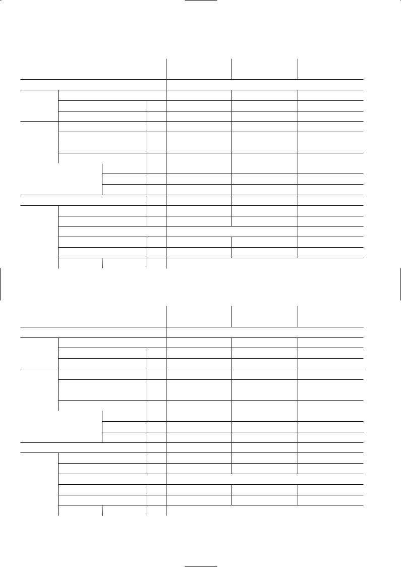
NOISE CRITERION CURVES |
|
|
|
|
|
|
|
|
|
|
|
|
|
||||||
SUH-1VR.TH |
|
|
|
|
|
<50Hz> |
SUH-1.6VR.TH |
|
|
|
|
|
<50Hz> |
||||||
|
|
|
SPL(dB) |
LINE |
|
|
|
SPL(dB) |
LINE |
||||||||||
|
|
|
|
|
|
|
|
47 |
|
SUH-1.6VR2.TH |
|
|
|
|
50 |
|
|||
|
|
|
|
|
|
|
|
|
|
|
|
|
|
|
|
||||
BAR |
90 |
|
|
|
|
|
|
|
|
BAR |
90 |
|
|
|
|
|
|
|
|
0.0002MICRO |
70 |
|
|
|
|
|
|
|
|
0.0002MICRO |
70 |
|
|
|
|
|
|
|
|
|
80 |
|
|
|
|
|
|
|
|
|
80 |
|
|
|
|
|
|
|
|
dB re |
|
|
|
|
|
|
|
|
NC-70 |
dB re |
|
|
|
|
|
|
|
|
NC-70 |
|
|
|
|
|
|
|
|
|
|
|
|
|
|
|
|
|
|
||
LEVEL, |
60 |
|
|
|
|
|
|
|
|
LEVEL, |
60 |
|
|
|
|
|
|
|
|
|
|
|
|
|
|
|
|
NC-60 |
|
|
|
|
|
|
|
|
NC-60 |
||
PRESSURE |
|
|
|
|
|
|
|
|
PRESSURE |
|
|
|
|
|
|
|
|
||
50 |
|
|
|
|
|
|
|
|
50 |
|
|
|
|
|
|
|
|
||
|
|
|
|
|
|
|
|
|
|
|
|
|
|
|
|
|
|
||
|
|
|
|
|
|
|
|
|
NC-50 |
|
|
|
|
|
|
|
|
|
NC-50 |
|
40 |
|
|
|
|
|
|
|
|
|
40 |
|
|
|
|
|
|
|
|
SOUND |
|
|
|
|
|
|
|
|
NC-40 |
SOUND |
|
|
|
|
|
|
|
|
NC-40 |
30 |
|
|
|
|
|
|
|
|
30 |
|
|
|
|
|
|
|
|
||
|
|
|
|
|
|
|
|
|
|
|
|
|
|
|
|
|
|
||
BAND |
|
|
|
|
|
|
|
|
NC-30 |
BAND |
|
|
|
|
|
|
|
|
NC-30 |
20 |
APPROXIMATE |
|
|
|
|
|
|
|
20 |
APPROXIMATE |
|
|
|
|
|
|
|||
OCTAVE |
|
|
|
|
|
|
|
OCTAVE |
|
|
|
|
|
|
|||||
|
|
|
|
|
|
|
THRESHOLD OF |
|
|
|
|
|
|
||||||
|
THRESHOLD OF |
|
|
|
|
|
|
|
|
|
|
|
|
|
|||||
|
|
|
|
|
|
|
NC-20 |
|
|
HEARING FOR |
|
|
|
|
|
NC-20 |
|||
|
|
HEARING FOR |
|
|
|
|
|
|
|
|
|
|
|
|
|
||||
|
|
|
|
|
|
|
|
|
|
CONTINUOUS |
|
|
|
|
|
||||
|
|
CONTINUOUS |
|
|
|
|
|
|
|
|
|
|
|
|
|
|
|
||
|
|
|
|
|
|
|
|
|
|
|
NOISE |
|
|
|
|
|
|
|
|
|
|
NOISE |
|
|
|
|
|
|
|
|
|
|
|
|
|
|
|
|
|
|
10 |
|
|
|
|
|
|
|
|
10 |
|
|
|
|
|
|
|
|
|
|
63 |
125 |
250 |
500 |
1000 |
2000 |
4000 |
8000 |
|
63 |
125 |
250 |
500 |
1000 |
2000 |
4000 |
8000 |
||
|
|
|
|
||||||||||||||||
|
|
|
BAND CENTER FREQUENCIES, Hz |
|
|
|
|
BAND CENTER FREQUENCIES, Hz |
|
||||||||||
SUH-2VR.TH |
|
|
|
|
|
<50Hz> |
SUH-2.5VR.TH |
|
|
|
|
|
<50Hz> |
||||||
|
|
|
SPL(dB) |
LINE |
|
|
NOTCH SPL(dB) |
LINE |
|||||||||||
SUH-2VR1.TH |
|
|
|
|
52 |
|
|
|
|
|
|
|
|
Hi |
53 |
|
|||
|
|
|
|
|
|
|
|
|
|
|
|
|
Lo |
51 |
|
||||
SUH-2VR2.TH |
|
|
|
|
|
|
|
|
|
|
|
|
|
|
|
|
|||
BAR |
90 |
|
|
|
|
|
|
|
|
BAR |
90 |
|
|
|
|
|
|
|
|
0.0002MICRO |
70 |
|
|
|
|
|
|
|
|
0.0002MICRO |
70 |
|
|
|
|
|
|
|
|
|
80 |
|
|
|
|
|
|
|
|
|
80 |
|
|
|
|
|
|
|
|
dB re |
|
|
|
|
|
|
|
|
NC-70 |
dB re |
|
|
|
|
|
|
|
|
NC-70 |
|
|
|
|
|
|
|
|
|
|
|
|
|
|
|
|
|
|
||
LEVEL, |
60 |
|
|
|
|
|
|
|
|
LEVEL, |
60 |
|
|
|
|
|
|
|
|
|
|
|
|
|
|
|
|
NC-60 |
|
|
|
|
|
|
|
|
NC-60 |
||
PRESSURE |
|
|
|
|
|
|
|
|
PRESSURE |
|
|
|
|
|
|
|
|
||
50 |
|
|
|
|
|
|
|
|
50 |
|
|
|
|
|
|
|
|
||
|
|
|
|
|
|
|
|
|
|
|
|
|
|
|
|
|
|
||
|
|
|
|
|
|
|
|
|
NC-50 |
|
|
|
|
|
|
|
|
|
NC-50 |
|
40 |
|
|
|
|
|
|
|
|
|
40 |
|
|
|
|
|
|
|
|
SOUND |
|
|
|
|
|
|
|
|
NC-40 |
SOUND |
|
|
|
|
|
|
|
|
NC-40 |
30 |
|
|
|
|
|
|
|
|
30 |
|
|
|
|
|
|
|
|
||
|
|
|
|
|
|
|
|
|
|
|
|
|
|
|
|
|
|
||
BAND |
|
|
|
|
|
|
|
|
NC-30 |
BAND |
|
|
|
|
|
|
|
|
NC-30 |
20 |
APPROXIMATE |
|
|
|
|
|
|
20 |
APPROXIMATE |
|
|
|
|
|
|
||||
OCTAVE |
|
|
|
|
|
|
OCTAVE |
|
|
|
|
|
|
||||||
THRESHOLD OF |
|
|
|
|
|
|
THRESHOLD OF |
|
|
|
|
|
|
||||||
|
|
|
|
|
|
|
|
|
|
|
|
|
|
||||||
|
|
|
|
|
|
|
|
|
|
|
|
|
|
|
|
||||
|
|
HEARING FOR |
|
|
|
|
|
NC-20 |
|
|
HEARING FOR |
|
|
|
|
|
NC-20 |
||
|
|
CONTINUOUS |
|
|
|
|
|
|
|
CONTINUOUS |
|
|
|
|
|
||||
|
|
|
|
|
|
|
|
|
|
|
|
|
|
|
|
||||
|
|
NOISE |
|
|
|
|
|
|
|
|
|
NOISE |
|
|
|
|
|
|
|
|
10 |
63 |
125 |
250 |
500 |
1000 |
2000 |
4000 |
8000 |
|
10 |
63 |
125 |
250 |
500 |
1000 |
2000 |
4000 |
8000 |
|
|
|
|
||||||||||||||||
|
|
|
BAND CENTER FREQUENCIES, Hz |
|
|
|
|
BAND CENTER FREQUENCIES, Hz |
|
||||||||||
6
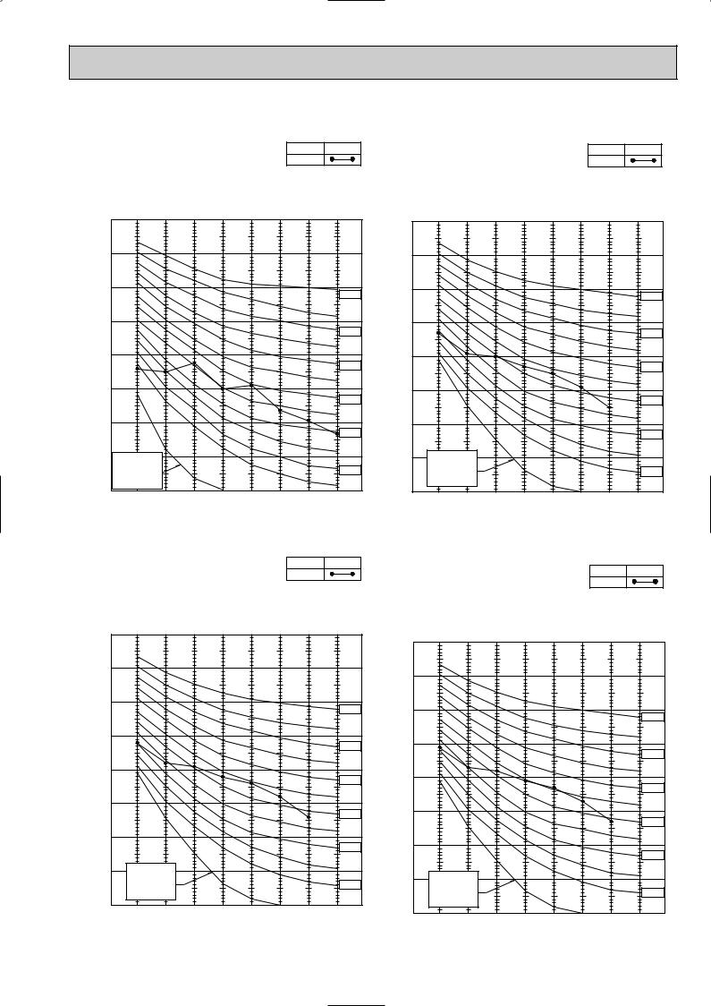
SU-1VR.TH |
|
|
|
|
|
|
<50Hz> |
SU-1.6VR.TH |
|
|
|
|
|
<50Hz> |
|||||
|
|
|
|
SPL(dB) |
LINE |
|
|
|
SPL(dB) |
LINE |
|||||||||
|
|
|
|
|
|
|
|
45 |
|
SU-1.6VR2.TH |
|
|
|
|
50 |
|
|||
|
|
|
|
|
|
|
|
|
|
|
|
|
|
|
|
||||
|
|
|
|
|
|
|
|
|
|
SU-1.6VR.TH-T |
|
|
|
|
|
|
|||
BAR |
90 |
|
|
|
|
|
|
|
|
BAR |
90 |
|
|
|
|
|
|
|
|
0.0002MICRO |
70 |
|
|
|
|
|
|
|
|
0.0002MICRO |
70 |
|
|
|
|
|
|
|
|
|
80 |
|
|
|
|
|
|
|
|
|
80 |
|
|
|
|
|
|
|
|
dB re |
|
|
|
|
|
|
|
|
NC-70 |
dB re |
|
|
|
|
|
|
|
|
NC-70 |
|
|
|
|
|
|
|
|
|
|
|
|
|
|
|
|
|
|
||
LEVEL, |
60 |
|
|
|
|
|
|
|
|
LEVEL, |
60 |
|
|
|
|
|
|
|
|
|
|
|
|
|
|
|
|
NC-60 |
|
|
|
|
|
|
|
|
NC-60 |
||
PRESSURE |
|
|
|
|
|
|
|
|
PRESSURE |
|
|
|
|
|
|
|
|
||
50 |
|
|
|
|
|
|
|
|
50 |
|
|
|
|
|
|
|
|
||
|
|
|
|
|
|
|
|
|
|
|
|
|
|
|
|
|
|
||
|
|
|
|
|
|
|
|
|
NC-50 |
|
|
|
|
|
|
|
|
|
NC-50 |
|
40 |
|
|
|
|
|
|
|
|
|
40 |
|
|
|
|
|
|
|
|
SOUND |
|
|
|
|
|
|
|
|
NC-40 |
SOUND |
|
|
|
|
|
|
|
|
NC-40 |
30 |
|
|
|
|
|
|
|
|
30 |
|
|
|
|
|
|
|
|
||
|
|
|
|
|
|
|
|
|
|
|
|
|
|
|
|
|
|
||
BAND |
|
|
|
|
|
|
|
|
NC-30 |
BAND |
|
|
|
|
|
|
|
|
NC-30 |
20 |
APPROXIMATE |
|
|
|
|
|
|
|
20 |
APPROXIMATE |
|
|
|
|
|
|
|||
OCTAVE |
|
|
|
|
|
|
|
OCTAVE |
|
|
|
|
|
|
|||||
|
THRESHOLD OF |
|
|
|
|
|
|
|
THRESHOLD OF |
|
|
|
|
|
|
||||
|
|
|
|
|
|
|
|
|
|
|
|
|
|
|
|
||||
|
|
|
|
|
|
|
NC-20 |
|
|
HEARING FOR |
|
|
|
|
|
NC-20 |
|||
|
|
HEARING FOR |
|
|
|
|
|
|
|
|
|
|
|
|
|
||||
|
|
|
|
|
|
|
|
|
|
CONTINUOUS |
|
|
|
|
|
||||
|
|
CONTINUOUS |
|
|
|
|
|
|
|
|
|
|
|
|
|
|
|
||
|
|
|
|
|
|
|
|
|
|
|
NOISE |
|
|
|
|
|
|
|
|
|
10 |
NOISE |
|
|
|
|
|
|
|
|
|
|
|
|
|
|
|
|
|
|
|
|
|
|
|
|
|
|
10 |
|
|
|
|
|
|
|
|
||
|
63 |
125 |
250 |
500 |
1000 |
2000 |
4000 |
8000 |
|
63 |
125 |
250 |
500 |
1000 |
2000 |
4000 |
8000 |
||
|
|
|
|
||||||||||||||||
|
|
|
BAND CENTER FREQUENCIES, Hz |
|
|
|
|
BAND CENTER FREQUENCIES, Hz |
|
||||||||||
SU-1.6NR.TH |
|
|
|
|
|
<60Hz> |
|
|
|
|
|
|
|
|
|
<50/60Hz> |
|||
|
|
|
SPL(dB) |
LINE |
SU-2VR.TH |
|
|
|
|
|
|
||||||||
|
|
|
|
|
|
|
SPL(dB) |
LINE |
|||||||||||
|
|
|
|
|
|
|
|
51 |
|
|
|
|
|
||||||
|
|
|
|
|
|
|
|
|
|
SU-2VR1.TH |
|
|
|
|
52 |
|
|||
|
|
|
|
|
|
|
|
|
|
SU-2NR.TH |
|
|
|
|
|
|
|
||
|
|
|
|
|
|
|
|
|
|
SU-2VR.TH-T |
|
|
|
|
|
|
|||
MICRO0.0002redBLEVEL,PRESSURESOUNDBANDOCTAVEBAR |
90 |
|
|
|
|
|
|
|
|
MICRO0.0002redBLEVEL,PRESSURESOUNDBANDOCTAVEBAR |
90 |
|
|
|
|
|
|
|
|
|
|
|
|
|
|
|
|
|
|
|
|
|
|
|
|
|
|||
80 |
|
|
|
|
|
|
|
|
80 |
|
|
|
|
|
|
|
|
||
|
|
|
|
|
|
|
|
|
|
|
|
|
|
|
|
|
|
||
|
|
|
|
|
|
|
|
|
|
|
|
|
|
|
|
|
|
|
|
|
70 |
|
|
|
|
|
|
|
NC-70 |
|
70 |
|
|
|
|
|
|
|
|
|
|
|
|
|
|
|
|
|
|
|
|
|
|
|
|
|
NC-70 |
||
|
|
|
|
|
|
|
|
|
|
|
|
|
|
|
|
|
|
|
|
|
60 |
|
|
|
|
|
|
|
|
|
60 |
|
|
|
|
|
|
|
|
|
|
|
|
|
|
|
|
|
NC-60 |
|
|
|
|
|
|
|
|
|
|
|
|
|
|
|
|
|
|
|
|
|
|
|
|
|
|
|
|
NC-60 |
|
|
|
|
|
|
|
|
|
|
|
|
|
|
|
|
|
|
|
|
|
|
50 |
|
|
|
|
|
|
|
|
|
50 |
|
|
|
|
|
|
|
|
|
|
|
|
|
|
|
|
|
NC-50 |
|
|
|
|
|
|
|
|
|
|
|
|
|
|
|
|
|
|
|
|
|
|
|
|
|
|
|
|
NC-50 |
|
|
|
|
|
|
|
|
|
|
|
|
|
|
|
|
|
|
|
|
|
|
40 |
|
|
|
|
|
|
|
|
|
40 |
|
|
|
|
|
|
|
|
|
|
|
|
|
|
|
|
|
NC-40 |
|
|
|
|
|
|
|
|
|
|
|
|
|
|
|
|
|
|
|
|
|
|
|
|
|
|
|
|
NC-40 |
|
|
|
|
|
|
|
|
|
|
|
|
|
|
|
|
|
|
|
|
|
|
30 |
|
|
|
|
|
|
|
|
|
30 |
|
|
|
|
|
|
|
|
|
|
|
|
|
|
|
|
|
NC-30 |
|
|
|
|
|
|
|
|
|
|
|
|
|
|
|
|
|
|
|
|
|
|
|
|
|
|
|
|
NC-30 |
|
|
|
|
|
|
|
|
|
|
|
|
|
|
|
|
|
|
|
|
|
|
20 |
APPROXIMATE |
|
|
|
|
|
|
|
|
|
|
|
|
|
|
|
|
|
|
THRESHOLD OF |
|
|
|
|
|
|
|
20 |
APPROXIMATE |
|
|
|
|
|
|
|||
|
|
|
|
|
|
|
|
|
|
|
|
|
|
|
|||||
|
|
HEARING FOR |
|
|
|
|
|
NC-20 |
|
THRESHOLD OF |
|
|
|
|
|
|
|||
|
|
|
|
|
|
|
|
|
|
|
|
|
|
|
|||||
|
|
CONTINUOUS |
|
|
|
|
|
|
|
HEARING FOR |
|
|
|
|
|
NC-20 |
|||
|
|
|
|
|
|
|
|
|
|
|
|
|
|
|
|||||
|
|
NOISE |
|
|
|
|
|
|
|
|
|
CONTINUOUS |
|
|
|
|
|
||
|
10 |
|
|
|
|
|
|
|
|
|
|
|
|
|
|
|
|||
|
63 |
125 |
250 |
500 |
1000 |
2000 |
4000 |
8000 |
|
10 |
NOISE |
|
|
|
|
|
|
|
|
|
|
|
63 |
125 |
250 |
500 |
1000 |
2000 |
4000 |
8000 |
|||||||||
|
|
|
BAND CENTER FREQUENCIES, Hz |
|
|
|
|||||||||||||
|
|
|
|
|
|
|
BAND CENTER FREQUENCIES, Hz |
|
|||||||||||
|
|
|
|
|
|
|
|
|
|
|
|
|
|
||||||
7
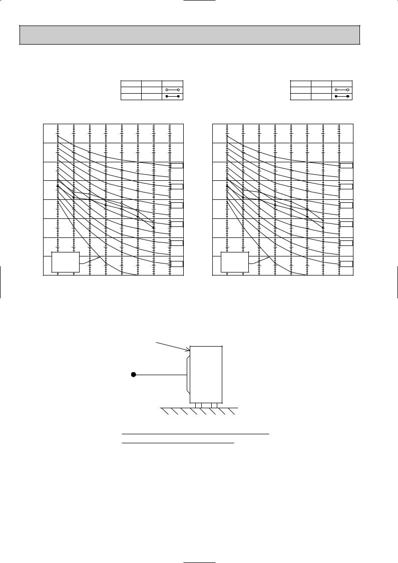
SU-2.5VR.TH |
|
|
|
|
|
<50Hz> |
|||
|
|
NOTCH |
SPL(dB) |
LINE |
|||||
SU-2.5VR.TH-T |
|
|
|
Hi |
53 |
|
|||
|
|
|
Lo |
50 |
|
||||
BAR |
90 |
|
|
|
|
|
|
|
|
|
|
|
|
|
|
|
|
|
|
0.0002 MICRO |
80 |
|
|
|
|
|
|
|
|
70 |
|
|
|
|
|
|
|
NC-70 |
|
dB re |
|
|
|
|
|
|
|
|
|
|
|
|
|
|
|
|
|
|
|
LEVEL, |
60 |
|
|
|
|
|
|
|
|
|
|
|
|
|
|
|
|
NC-60 |
|
|
|
|
|
|
|
|
|
|
|
PRESSURE |
50 |
|
|
|
|
|
|
|
|
|
|
|
|
|
|
|
|
NC-50 |
|
40 |
|
|
|
|
|
|
|
|
|
|
|
|
|
|
|
|
|
NC-40 |
|
SOUND |
|
|
|
|
|
|
|
|
|
30 |
|
|
|
|
|
|
|
|
|
BAND |
|
|
|
|
|
|
|
|
NC-30 |
20 |
APPROXIMATE |
|
|
|
|
|
|
||
OCTAVE |
|
|
|
|
|
|
|||
THRESHOLD OF |
|
|
|
|
|
|
|||
|
|
|
|
|
|
|
|||
|
HEARING FOR |
|
|
|
|
|
NC-20 |
||
|
CONTINUOUS |
|
|
|
|
|
|||
|
|
|
|
|
|
|
|||
|
NOISE |
|
|
|
|
|
|
|
|
10 |
|
|
|
|
|
|
|
|
|
|
63 |
125 |
250 |
500 |
1000 |
2000 |
4000 |
8000 |
|
|
|
||||||||
BAND CENTER FREQUENCIES, Hz
SU-2.5NR.TH |
|
|
|
|
|
<60Hz> |
|||
|
|
NOTCH |
SPL(dB) |
LINE |
|||||
|
|
|
|
|
|
|
Hi |
54 |
|
|
|
|
|
|
|
|
Lo |
50 |
|
BAR |
90 |
|
|
|
|
|
|
|
|
|
|
|
|
|
|
|
|
|
|
0.0002 MICRO |
80 |
|
|
|
|
|
|
|
|
70 |
|
|
|
|
|
|
|
NC-70 |
|
dB re |
|
|
|
|
|
|
|
|
|
|
|
|
|
|
|
|
|
|
|
LEVEL, |
60 |
|
|
|
|
|
|
|
|
|
|
|
|
|
|
|
|
NC-60 |
|
|
|
|
|
|
|
|
|
|
|
PRESSURE |
50 |
|
|
|
|
|
|
|
|
|
|
|
|
|
|
|
|
NC-50 |
|
40 |
|
|
|
|
|
|
|
|
|
|
|
|
|
|
|
|
|
NC-40 |
|
SOUND |
|
|
|
|
|
|
|
|
|
30 |
|
|
|
|
|
|
|
|
|
BAND |
|
|
|
|
|
|
|
|
NC-30 |
20 |
APPROXIMATE |
|
|
|
|
|
|
||
OCTAVE |
|
|
|
|
|
|
|||
THRESHOLD OF |
|
|
|
|
|
|
|||
|
|
|
|
|
|
|
|||
|
HEARING FOR |
|
|
|
|
|
NC-20 |
||
|
CONTINUOUS |
|
|
|
|
|
|||
|
|
|
|
|
|
|
|||
|
NOISE |
|
|
|
|
|
|
|
|
10 |
|
|
|
|
|
|
|
|
|
|
63 |
125 |
250 |
500 |
1000 |
2000 |
4000 |
8000 |
|
|
|
||||||||
BAND CENTER FREQUENCIES, Hz
UNIT
1m
MICROPHONE
Ambient temperature 35°C (Cooling) / 7°C (Heating)
Test conditions are based on JIS Z8731
8
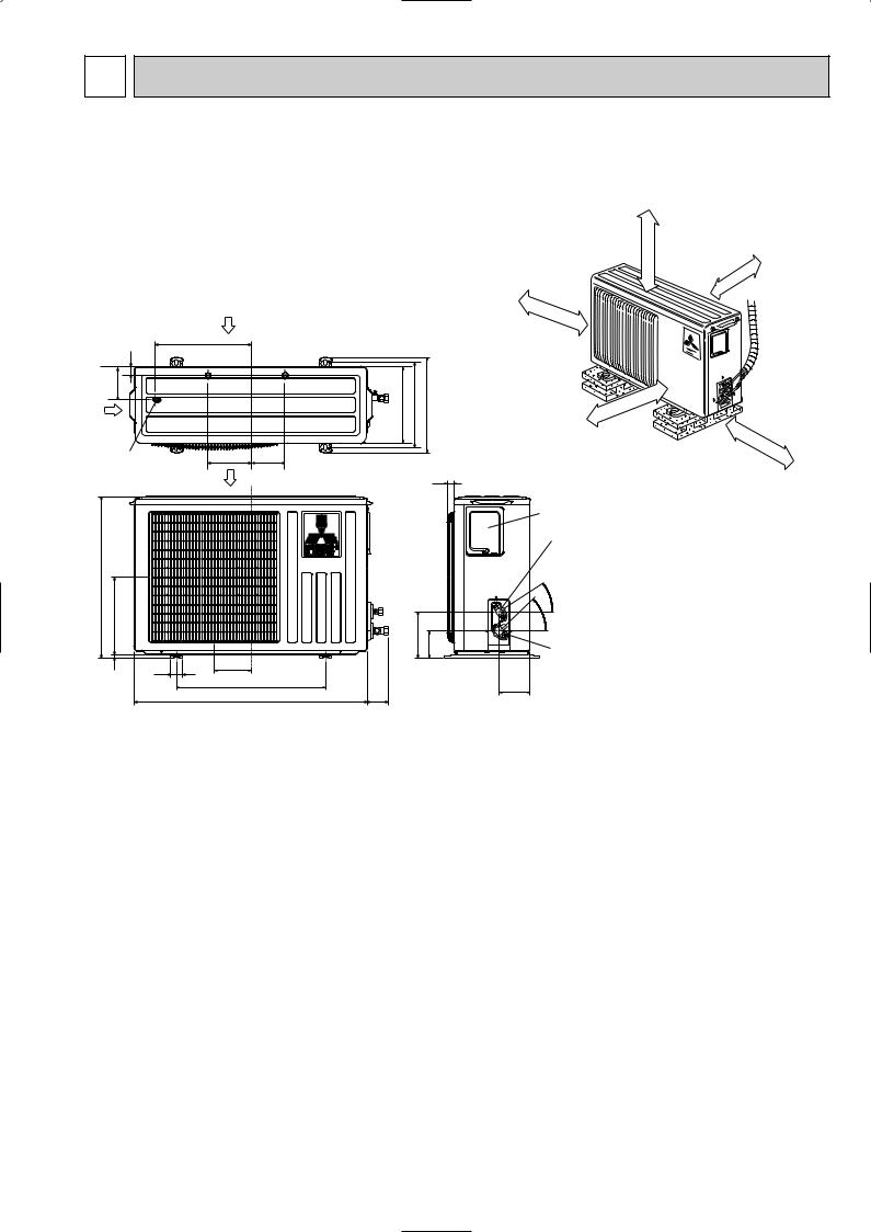
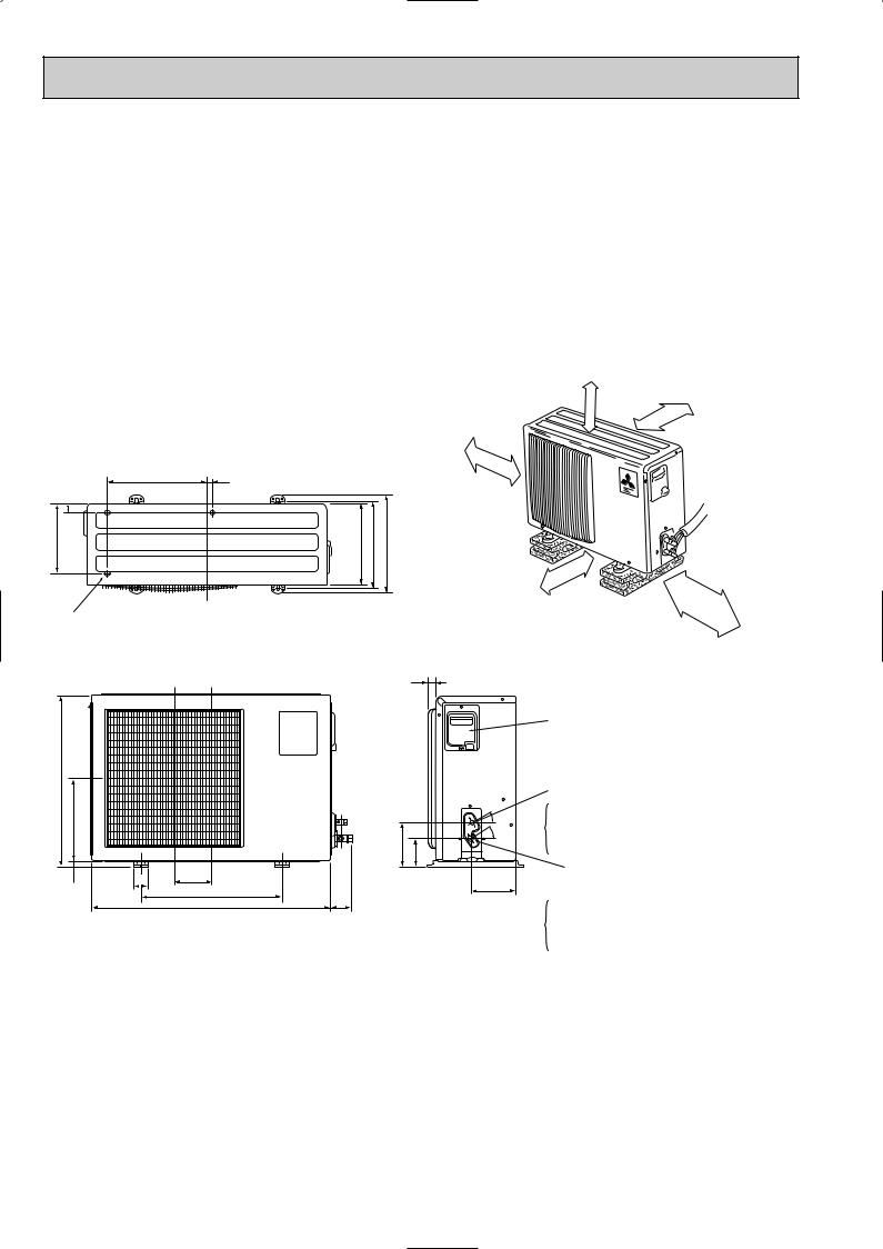
6 OUTLINES AND DIMENSIONS
SUH-1VR.TH
SU-1VR.TH
109 32
Air in
Drainage 3holes [33
540
260 |
|
10 |
40 |
Air in
320
255 285 320
147 |
110 |
|
|
Air out |
25 |
155 90
122
500 |
74 |
780 |
REQUIRED SPACE |
or more |
|
|
A |
|
|
10cm |
|
|
|
|
|
Outdoor |
|
10cm |
unit |
|
or |
|
|
|
|
|
If clearance |
more |
|
|
|
|
behind the outdoor |
|
|
units only 40B or 50B |
|
|
side A must be |
|
|
fully open. |
|
|
|
or |
more |
|
|
|
|
40cm |
|
Service panel
Liquid refrigerant pipe joint Refrigerant pipe
(flared) [6.35
- 35
- 43
Gas refrigerant pipe joint
104 Refrigerant pipe (flared) [9.52
Unit: mm
or |
more |
|
10cm
35cm |
or |
more |
|
||
|
|
9
SUH-1.6VR.TH SUH-1.6VR2.TH
SU-1.6NR.TH SU-1.6VR.TH SU-1.6VR2.TH SU-1.6VR.TH-T
SUH-2VR.TH
SUH-2VR1.TH
SUH-2VR2.TH
SU-2NR.TH SU-2.5NR.TH
SU-2VR.TH SU-2.5VR.TH
SU-2VR1.TH
SU-2VR.TH-T SU-2.5VR.TH-T
Unit: mm
|
|
|
|
|
|
|
|
|
sides |
|
|
|
|
|
|
|
right/left |
only |
|||
|
|
|
|
|
|
. |
||||
|
|
|
|
|
|
|
|
|
has |
|
|
thefront |
|
|
unobstructed |
||||||
|
|
|
|
|
or |
the |
top |
|
|
|
|
|
|
vacant, |
|
|
|
||||
|
If |
|
|
|
|
|
|
|||
more |
are |
be |
10cm |
|
|
|
|
|||
|
|
|
|
|
|
|
||||
or |
|
to |
|
|
|
|
|
|
|
|
10cm |
|
|
|
10cm |
more |
|
|
|||
|
|
|
|
|
|
or |
|
|
|
|
35
248
Drainage 3holes  16.2
16.2
605
20 292
350 20
290 |
310 |
345 |
30
157 |
100 |
50 183
500 |
74 |
850 |
10cm |
or |
|
more |
more |
|
|
|
|
or |
|
|
|
|
50cm |
35cm |
|
|
|
If the right/left sides or |
or |
more |
||
|
back side is vacant,the front has only to be 50cm unobstructed.
Service panel
Liquid refrigerant
|
pipe joint |
|
|
Refrigerant pipe |
|
30 |
(flare) |
|
[6.35 (SUH-1.6/2VR(2).TH) (SU-1.6/2NR.TH) |
||
|
||
35 |
(SU-1.6/2VR(2).TH,SU-1.6/2VR.TH-T) |
|
[9.52 (SU-2.5NR.TH) |
||
|
||
|
(SU-2.5VR.TH,SU-2.5VR.TH-T) |
|
|
Gas refrigerant |
|
|
pipe joint |
|
161 |
Refrigerant pipe |
|
|
(flare) |
|
|
[12.7 (SUH-1.6VR(2).TH) (SU-1.6NR.TH) |
(SU-1.6VR(2).TH,SU-1.6VR.TH-T) [15.88 (SUH-2VR.TH) (SU-2/2.5NR.TH)
(SU-2/2.5VR.TH,SU-2/2.5VR.TH-T)
10
11
|
|
|
|
|
|
|
|
|
|
200 |
2-SUH |
|
|
|
|
|
|
|
|
|
|
Unit : mm |
|
|
|
|
|
|
|
|
|
Outdoor Unit-Necessary surrounding clearance |
|
||
|
|
|
|
|
|
|
|
|
|
|
. |
Outdoor Unit-Necessary surrounding clearance |
185 |
500 |
185 |
17 |
|
|
|
|
.5VR |
||
|
Air intake |
|
|
|
Note:Allow adequate |
||||||
(Concentrated installation) |
The upper side must be open. |
|
|
|
|
||||||
|
|
200 |
|
|
39.5 27.5 |
362 |
10 |
10 |
upper clearance |
||
100 |
10 |
Air outlet |
|
15330 |
10 |
500 |
150 |
TH |
|||
|
|
|
|
|
|
|
|
|
Front opening |
|
|
|
|
|
Air intake |
|
|
|
|
|
|
|
|
|
For 10 units or less |
1000 |
|
|
|
|
|
|
Service space |
|
|
|
|
|
|
|
|
|
500 |
|
|
||
Handle for moving
138
95
Rear piping hole
More than 10 mm
Open as a rule
More than 500 mm if the back both sides and top are open.
7 |
295 |
24 |
|
|
|
Outlet guide |
|
Side air intake |
|
installation hole |
|
|
|
|
|
Rear fresh |
|
|
|
air intake |
|
Handle for moving |
|
|
|
|
|
|
|
|
524 |
|
|
441 |
|
|
|
|
179 |
23 |
|
33 |
40 |
Open as a rule |
|
|
|
More than 500 mm if the |
|
||
front and both sides are open. |
|
||
Drain hole
More than 100 mm
More than 200 mm if three area obstacles to both sides.
More than 350 mm
870
302
403
524
2-12o23 Oval holes (standard bolt M10)
Drain hole
Terminal block for indoor and outdoor unit connection
Terminal block for power line
Handle for moving |
|
|
|
|
||||
Service panel |
|
|
|
|
||||
|
|
|
|
850 |
|
|
|
|
|
|
|
553 |
Refrigerant-pipe flared |
|
|
|
|
|
|
|
|
|
|
|
||
337 |
352 |
|
|
connection [15.88 5/8F |
|
45 |
||
|
|
Refrigerant-pipe flared |
|
|
||||
|
|
|
|
connection [9.52 3/8F |
|
|
|
|
60 |
|
|
Knock out hole |
|
|
60 |
53 |
|
|
|
|
|
Knock out holes for |
||||
|
|
for front piping |
|
|
||||
|
|
|
|
|
|
120 |
||
|
|
|
|
(refrigerant,drainage |
|
power line 2-[27 |
||
|
|
|
|
and wiring) |
|
|
|
|
104 |
|
|
|
Knock out hole |
|
|
|
|
33 |
42 |
45 |
|
|
|
|
|
|
|
for right piping |
|
|
|
|
|||
|
|
|
|
|
|
|
|
|
|
|
|
|
(refrigerant,drainage |
|
R20 |
|
|
|
|
|
|
and wiring) |
R20 |
|
|
|
|
|
|
|
|
|
|
||
Bottom |
|
|
|
|
|
|||
|
|
|
|
80 |
max.25 |
|||
piping hole |
|
|
||||||
|
|
|
|
|||||
2-U-shaped |
|
R6 |
|
|
|
Standard bolt length |
||
|
|
|
|
|
||||
notched |
|
|
|
|
65 |
|
||
|
|
|
|
|
|
|||
holes |
|
|
|
17 |
|
|
|
|
|
|
|
|
|
|
|
||
|
|
|
|
|
|
|
|
|
|
|
|
|
12 |
Front right piping holes- |
|||
|
|
|
|
detail figures |
|
|||
|
|
|
|
|
|
|||
7 
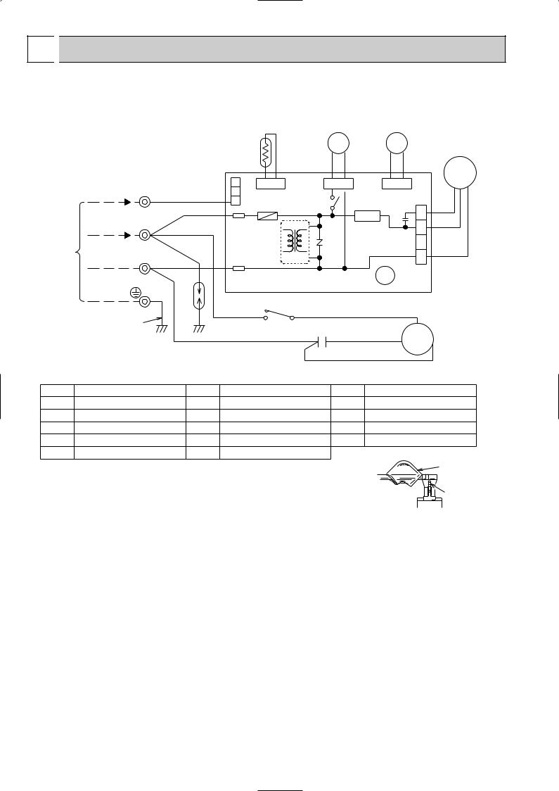
 WIRING DIAGRAM
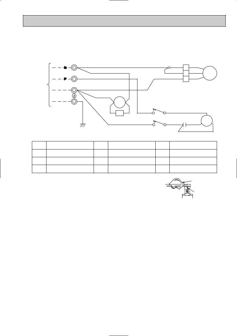
SUH-1VR.TH
TO INDOOR UNIT CONNECTING
TB 12VDC 3 w
220-240V~ 2 w
N w
GRN/YLW
|
|
RT61 |
|
|
21S4 |
52C |
|
|
||
|
|
|
|
BLK BLK |
VLT |
VLT |
|
|
||
|
|
|
|
|
|
|
MF |
|||
|
|
3 |
CN611 |
|
CN721 |
CN720 |
|
|||
|
|
|
|
|
||||||
RED |
|
2 CN730 |
|
|
X62 |
|
|
|
|
|
WHT |
1 |
F61 |
|
|
|
C65 |
|
RED |
||
w |
|
|
|
SR61 |
1 |
|||||
|
|
TAB21 |
|
|
|
|
WHT |
|||
|
|
|
|
|
|
2 |
||||
|
|
|
|
NR61 |
|
|
||||
WHT |
|
|
IC881 |
TRANS |
|
|
BLK |
|||
|
|
|
|
4 |
||||||
|
|
|
|
|
|
|
|
|
3 |
|
BLU |
|
w |
|
|
|
|
|
CN711 |
|
|
DSAR |
|
TAB20 |
|
|
|
X62 |
|
|||
|
|
DEICER P.C. BOARD |
|
|
|
|||||
|
|
|
|
|
|
|||||
|
|
|
52C |
COM |
WHT |
|
|
|
||
|
WHT NO |
|
|
C |
|
|||||
|
|
|
|
|
|
C1 |
|
|
|
|
|
|
BLU |
|
|
|
|
|
|
|
|
|
|
|
|
|
RED |
S MC |
|
|||
|
|
|
|
|
|
BLK |
R |
|||
|
|
|
|
|
|
|
|
|
||
SYMBOL |
NAME |
SYMBOL |
NAME |
SYMBOL |
NAME |
C1 |
COMPRESSOR CAPACITOR |
MC |
COMPRESSOR (INNER THERMOSTAT) |
TB |
TERMINAL BLOCK |
C65 |
FAN MOTOR CAPACITOR |
MF |
FAN MOTOR (INNER THERMOSTAT) |
X62 |
4-WAY VALVE RELAY |
DSAR |
SURGE ABSORBER |
NR61 |
VARISTOR |
21S4 |
4-WAY VALVE SOLENOID COIL |
F61 |
FASE (2A) |
RT61 |
DEFROST THERMISTOR |
52C |
COMPRESSOR CONTACTOR |
IC881 |
DC/DC CONVERTER |
SR61 |
SOLID STATE RELAY |
|
|
NOTE :1. Use copper conductors only (For field wiring).
2.“w” shows the terminals with a lock mechanism, so they cannot be removed when you pull the lead wire.
Be sure to pull the lead wire by pushing the locking lever (projected part) of the terminal with a finger.
sleeve
locking lever
1 Slide the sleeve.
2Pull the wire while pushing the locking lever.
12
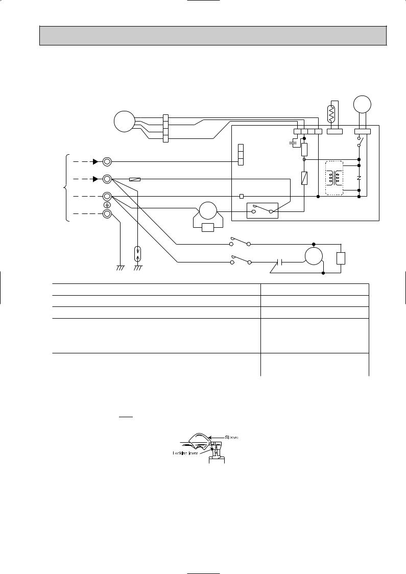
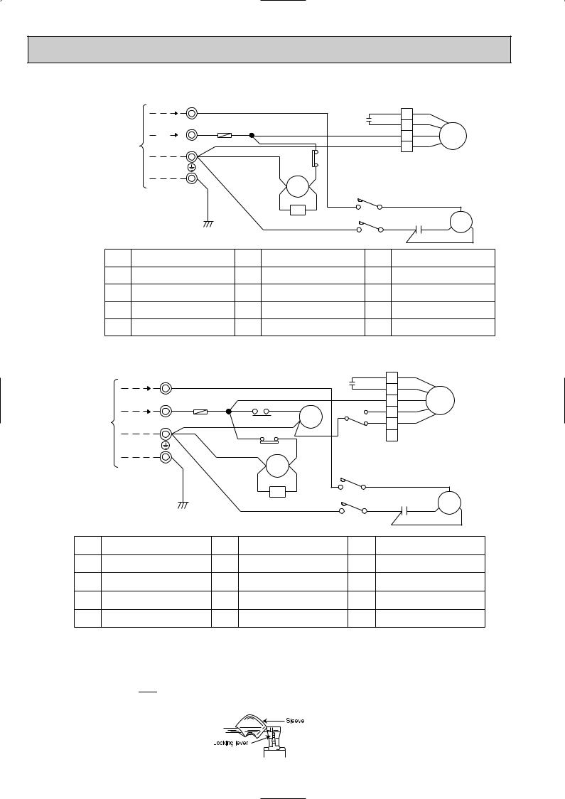
SUH-1.6VR.TH SUH-2VR.TH
SUH-1.6VR2.TH SUH-2VR1.TH
SUH-2VR2.TH
RT61
21S4
TO INDOOR UNIT CONNECTING
|
MF |
|
TB |
|
|
3 |
W |
|
12VDC |
|
|
2 |
W |
F |
220-240V |
WHT |
N W
WHT
GRN/YLW |
DSAR |
BLK |
|
BLK |
|
|
|
|
|
|
|
|
4 WHT |
|
|
|
|
|
|
|
|
||
WHT |
3 |
|
|
|
|
|
|
|
|
|
ORN |
2 |
RED |
|
|
|
|
CN711 1 |
2 |
3 |
4 |
RED |
1 |
|
CN730 |
|
C65 |
|
|
|
||
|
|
|
SR61 |
|
|
|||||
|
|
|
|
3 |
|
|
|
|
||
|
|
|
|
|
|
|
|
|
|
|
RED |
|
|
|
2 |
|
|
|
|
|
|
|
|
|
1 |
|
|
|
|
|
|
|
|
|
|
|
|
|
|
|
|
|
|
WHT |
|
|
|
|
F61 |
|
|
|
||
|
|
|
|
W |
|
|
|
|
|
|
|
|
|
|
|
|
|
|
|
|
|
BLU |
|
|
|
TAB20 |
|
|
|
|
|
|
|
|
|
|
|
|
|
|
|
|
|
|
|
BLU |
52C1 A2 YLW |
52C |
|
|
|
|||
|
|
A1 |
|
|
|
|||||
|
|
W 4 |
W |
|
|
|
||||
|
|
|
|
|
3 |
|
|
|
||
|
|
VLT |
CR YLW |
52C1 |
|
|
|
|
|
|
|
|
WHT |
|
|
WHT |
|
|
|
||
|
|
|
|
|
|
|
|
|
||
|
|
|
L1/1 |
T1/2 |
|
|
C |
|
|
|
|
|
|
BLU C1 W RED S |
MC |
||||||
|
|
BLU |
|
|
|
|||||
|
|
|
L3/5 |
T3/6 |
W |
W BLK |
|
|
|
|
BLK
BLK
CN661 CN721
X62
IC881
NR61
TRANS
DEICER
P.C. BOARD
|
WHT |
R |
CZ |
|
WHT |
SYMBOL |
NAME |
SYMBOL |
NAME |
SYMBOL |
NAME |
C1 |
COMPRESSOR CAPACITOR |
RT61 |
DEFROST THERMISTOR |
IC881 |
DC/DC CONVERTER |
C65 |
FAN MOTOR CAPACITOR |
SR61 |
SOLID STATE RELAY |
DSAR |
SURGE ABSORBER 1 |
F61 |
FUSE (2A) |
TB |
TERMINAL BLOCK |
CR |
SURGE ABSORBER 2 |
|
|
|
|
|
|
F |
FUSE (2A) |
X62 |
4-WAY VALVE RELAY |
CZ |
SURGE ABSORBER 3 |
|
|
|
|
|
|
MC |
COMPRESSOR |
21S4 |
4-WAY VALVE SOLENOID COIL |
|
|
<INNER THERMOSTAT> |
|
|
|||
MF |
FAN MOTOR |
52C |
CONTACTOR |
|
|
<INNER THERMOSTAT> |
|
|
|||
|
|
|
|
|
|
NR61 |
VARISTOR |
52C1 |
COMPRESSOR CONTACTOR |
|
|
|
|
|
|
|
|
NOTE :1. Use copper conductors only. (For field wiring)
2.Since the indoor and outdoor unit connecting wires have polarity, connect them according to the numbers (N,2,3 and ;).
3.Symbols below indicate.
/:Terminal block,  : Connector
4.”w” shows the terminals with a lock mechanism,so they cannot be removed when you pull the lead wire. Be sure to pull the wire by pushing the locking lever (projected part) of the terminal with a finger.
1Slide the sleeve.
2Pull the wire while pushing the locking lever.
13
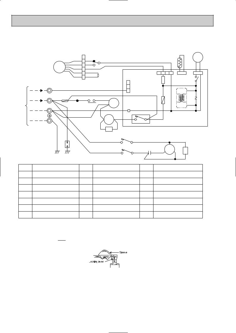
SUH-2.5VR.TH
TO INDOOR UNIT CONNECTING
MF
|
TB |
12VDC |
3 W |
220-240V~ 2 WWHT
N
W
GRN/YLW |
DSAR |
YLW 6 |
YLW |
1 X1 |
|
|
|
BRN |
|
|
BLK |
5 |
BLK |
5 |
|
|
|
|
|
|
|
|
|
|
|
|||
WHT |
4 |
WHT |
3 |
|
|
|
|
|
ORN |
3 |
ORN |
|
|
|
|
|
|
2 |
C2 |
|
|
|
|
CN711 1 |
||
RED |
1 |
RED |
|
CN730 |
|
|||
|
|
|
|
|
|
|
3 |
|
RED |
|
|
|
|
|
|
2 |
|
|
|
|
|
|
|
1 |
|
|
|
|
WHT |
|
|
|
|
||
|
|
|
|
|
|
|
||
F ORN RED |
RED8 |
|
|
|
F61 |
|||
TB2 |
26F1 BLU 7 |
X1 |
W |
|
||||
|
|
|||||||
BLU |
|
|
|
|
|
TAB20 |
|
|
|
|
|
VLT |
|
A2 |
YLW |
52C |
|
|
|
|
A1 |
|
||||
|
|
|
52C1 |
|
3 W |
4 W |
||
WHT |
|
|
|
|
|
|
||
|
|
VLT |
CR |
YLW |
|
|
|
|
|
|
|
|
|
|
|||
|
|
|
|
|
|
|
||
|
|
WHT |
|
52C1 |
|
|||
|
|
|
|
|
|
WHT |
||
|
|
|
|
|
L1/1 |
|
T1/2 |
|
|
|
BLU |
|
|
|
BLU C1 RED |
||
|
|
|
|
|
L3/5 |
T3/6 |
BLK |
|
|
|
|
|
|
|
|
|
|
2 3 4
SR61
C
S MC
RT61
21S4
BLK
BLK
CN661 CN721
X62
IC881
NR61
TRANS
|
DEICER |
|
P.C. BOARD |
|
WHT |
R |
CZ |
|
|
|
WHT |
SYMBOL |
NAME |
SYMBOL |
NAME |
SYMBOL |
NAME |
|
C1 |
COMPRESSOR CAPACITOR |
RT61 |
DEFROST THERMISTOR |
X1 |
FAN MOTOR RELAY |
|
C2 |
FAN MOTOR CAPACITOR |
SR61 |
SOLID STATE RELAY |
26F1 |
THERMAL REED SWITCH |
|
F61 |
FUSE (2A) |
TB,TB2 |
TERMINAL BLOCK |
IC881 |
DC/DC CONVERTER |
|
F |
FUSE (2A) |
X62 |
4-WAY VALVE RELAY |
DSAR |
SURGE ABSORBER 1 |
|
MC |
COMPRESSOR |
21S4 |
4-WAY VALVE SOLENOID COIL |
CR |
SURGE ABSORBER 2 |
|
<INNER THERMOSTAT> |
||||||
MF |
FAN MOTOR |
52C |
CONTACTOR |
CZ |
SURGE ABSORBER 3 |
|
<INNER THERMOSTAT> |
||||||
|
|
|
|
|
||
NR61 |
VARISTOR |
52C1 |
COMPRESSOR CONTACTOR |
|
|
NOTE :1. Use copper conductors only. (For field wiring)
2.Since the indoor and outdoor unit connecting wires have polarity, connect them according to the numbers (N,2,3 and ;).
3.Symbols below indicate.
/:Terminal block,  : Connector
4.”w” shows the terminals with a lock mechanism,so they cannot be removed when you pull the lead wire. Be sure to pull the wire by pushing the locking lever (projected part) of the terminal with a finger.
1Slide the sleeve.
2Pull the wire while pushing the locking lever.
14
SU-1VR.TH |
|
|
|
|
|
|
|
|
|
|
|
|
||
|
|
TB |
|
|
|
|
|
|
|
|
|
|
|
|
|
INDOOR UNIT CONNECTING |
220-240V~ 3 |
w |
RED |
|
|
|
|
C2 RED 3 RED |
|
||||
|
220-240V~ |
2 |
w |
RED |
|
|
|
|
|
WHT 1 WHT |
MF |
|||
|
|
WHT |
|
|
|
|
|
BLU |
2 |
BLK |
|
|||
|
|
|
|
|
|
|
|
|
|
|
|
|
||
|
|
N |
w |
|
|
|
|
|
|
|
|
|
|
|
|
|
|
|
|
|
|
|
|
|
|
|
|
||
TO |
|
|
|
BLU |
|
|
|
|
|
|
|
|
|
|
|
|
|
A2 |
52C |
A1 |
|
|
|
|
|
|
|||
|
|
|
|
GRN/YLW |
|
52C |
|
|
|
|
||||
|
|
|
|
|
|
|
|
|
|
|
WHT |
|
||
|
|
|
|
VLT CR YLW |
|
|
|
|
C |
|||||
|
|
|
|
L1/1 T1/2 |
|
|
|
|||||||
|
|
|
|
|
|
BLU |
|
BLU C1 RED S MC R |
||||||
|
|
|
|
|
|
|
|
|
L3/5 T3/6 |
|
|
BLK |
|
|
|
SYMBOL |
NAME |
|
SYMBOL |
|
|
NAME |
|
SYMBOL |
|
|
NAME |
|
|
|
CR |
SURGE ABSORBER |
MC |
COMPRESSOR (INNER THERMOSTAT) |
52C |
COMPRESSOR CONTACTOR |
||||||||
C1 |
COMPRESSOR CAPACITOR |
MF |
FAN MOTOR (INNER THERMOSTAT) |
C2 |
FAN MOTOR CAPACITOR |
TB |
TERMINAL BLOCK |
NOTE :1. Use copper conductors only (For field wiring).
2.“w” shows the terminals with a lock mechanism, so they cannot be removed when you pull the lead wire.
Be sure to pull the lead wire by pushing the locking lever (projected part) of the terminal with a finger.
sleeve
locking lever
1 Slide the sleeve.
2Pull the wire while pushing the locking lever.
15
SU-1.6NR.TH |
|
TB |
|
|
|
|
|
|
|
|
|
|
|
|
|
|
|
SU-2NR.TH |
|
|
|
|
|
|
|
|
|
|
|
|
|
|
|
||
|
2 |
W |
|
|
|
|
|
|
|
|
|
|
|
|
|
|
|
|
|
220V, 60Hz |
|
|
|
WHT |
|
|
|
|
|
RED |
1 |
RED |
|
|
|
|
|
|
|
|
|
|
|
|
C2 |
|
|
|
|
||||
|
UNIT CONNECTING |
3 |
|
|
|
|
|
|
|
|
ORN |
2 |
ORN |
|
|
|
|
INDOORTO |
WRED |
F |
RED TB2 |
|
BLK 26C |
|
|
|
|
|
|||||||
220V, 60Hz |
|
|
|
WHT |
3 |
WHT |
|
MF |
|
||||||||
|
|
|
|
|
|
|
|
||||||||||
|
|
|
|
|
|
|
BLK |
|
|
|
|
BLU |
BLK |
|
|
||
|
|
N |
|
|
|
|
|
|
|
|
4 |
|
|
|
|||
|
|
W |
BLU |
|
|
|
|
|
|
|
|
|
|
|
|
||
|
|
|
|
|
|
|
|
|
|
|
|
|
|
|
|
||
|
|
|
|
|
|
|
A2 |
52C |
A1 |
52C |
|
|
|
|
|
|
|
|
|
|
GRN/YLW |
|
|
|
|
|
|
|
|
|
|
|
|
||
|
|
|
|
|
|
|
CR |
|
|
|
|
|
WHT |
|
|
|
|
|
|
|
|
|
|
|
|
|
|
|
|
|
|
|
|
||
|
|
|
|
|
|
|
VLT |
YLW |
L1/1 |
T1/2 |
|
|
|
C |
|
||
|
|
|
|
|
|
|
|
|
|
|
|
|
|||||
|
|
|
|
|
|
|
|
BLU |
|
|
|
BLU |
C1 |
RED |
S |
MC |
R |
|
|
|
|
|
|
|
|
|
|
L3/5 |
T3/6 |
|
BLK |
|
|
|
|
|
|
|
|
|
|
|
|
|
|
|
|
|
|
|
|
|
|
SYMBOL |
NAME |
|
|
|
SYMBOL |
|
NAME |
|
SYMBOL |
|
NAME |
|
|||||
CR |
SURGE ABSORBER |
|
|
MC |
COMPRESSOR |
|
52C |
COMPRESSOR CONTACTOR |
|||||||||
|
|
(INNER THERMOSTAT) |
|||||||||||||||
|
|
|
|
|
|
|
|
|
|
|
|
|
|
||||
C1 |
|
COMPRESSOR CAPACITOR |
MF |
FAN MOTOR |
|
|
26C |
THERMAL SWITCH |
|
||||||||
|
(INNER THERMOSTAT) |
|
|||||||||||||||
|
|
|
|
|
|
|
|
|
|
|
|
|
|
||||
C2 |
|
FAN MOTOR CAPACITOR |
|
TB |
TERMINAL BLOCK |
|
|
|
|
|
|
|
|
||||
F |
|
FUSE(2A) |
|
|
|
TB2 |
TERMINAL BLOCK |
|
|
|
|
|
|
|
|
||
SU-2.5NR.TH
CONNECTING
UNIT
TO INDOOR
TB |
|
|
|
|
|
|
|
|
|
|
RED |
|
RED |
|
2 |
W |
|
|
|
|
|
|
|
C2 |
|
|
1 |
||
220V, 60Hz |
|
|
|
WHT |
|
|
|
|
|
|
ORN |
2 |
ORN |
|
|
|
|
|
|
|
|
|
|
|
|
||||
3 |
|
|
|
|
|
|
|
|
|
|
|
WHT |
3 |
WHT |
220V, 60Hz |
W |
RED |
F |
RED RED |
|
RED |
8 |
|
5 |
|
3 |
BLK |
4 |
MF |
|
|
|
|
|
|
|
|
|
BLK |
|||||
|
|
|
|
TB2 |
|
|
7 |
X1 |
|
|
|
YLW |
|
YLW |
N W |
|
|
26F1 |
BLU |
|
|
|
X1 |
|
5 |
||||
|
|
|
|
|
|
ORN |
1 |
|
|
|||||
|
|
|
|
BLK 26C BLK |
|
|
|
|
6 |
|
||||
|
|
|
|
|
|
|
|
|
|
|||||
|
|
|
|
BLU |
|
|
|
|
|
|
|
|
|
|
|
GRN/YLW |
|
A2 |
52C |
A1 |
|
L1/1 |
T1/2 |
|
|
C |
|||
|
|
VLT |
|
CR |
YLW |
|
|
|
||||||
|
|
|
|
|
|
|
|
|
52C |
|
|
|
WHT |
|
|
|
|
|
|
|
|
|
|
|
|
|
|
|
|
|
|
|
|
|
|
BLU |
|
|
|
|
|
BLU C1 |
RED S MC R |
|
|
|
|
|
|
|
|
|
|
L3/5 |
T3/6 |
|
BLK |
||
SYMBOL |
NAME |
SYMBOL |
NAME |
SYMBOL |
NAME |
|
CR |
SURGE ABSORBER |
MC |
COMPRESSOR |
X1 |
FAN MOTOR RELAY |
|
(INNER THERMOSTAT) |
||||||
|
|
|
|
|
||
C1 |
COMPRESSOR CAPACITOR |
MF |
FAN MOTOR |
26F1 |
THERMAL LEAD SWITCH |
|
(INNER THERMOSTAT) |
||||||
|
|
|
|
|
||
C2 |
FAN MOTOR CAPACITOR |
TB |
TERMINAL BLOCK |
52C |
COMPRESSOR CONTACTOR |
|
F |
FUSE(2A) |
TB2 |
TERMINAL BLOCK |
26C |
THERMAL SWITCH |
NOTE :1. Use copper conductors only. (For field wiring)
2.Since the indoor and outdoor unit connecting wires have polarity, connect them according to the numbers (N,2,3 and ;).
3.Symbols below indicate.
/:Terminal block,  : Connector
4.”w” shows the terminals with a lock mechanism,so they cannot be removed when you pull the lead wire. Be sure to pull the wire by pushing the locking lever (projected part) of the terminal with a finger.
1Slide the sleeve.
2Pull the wire while pushing the locking lever.
16
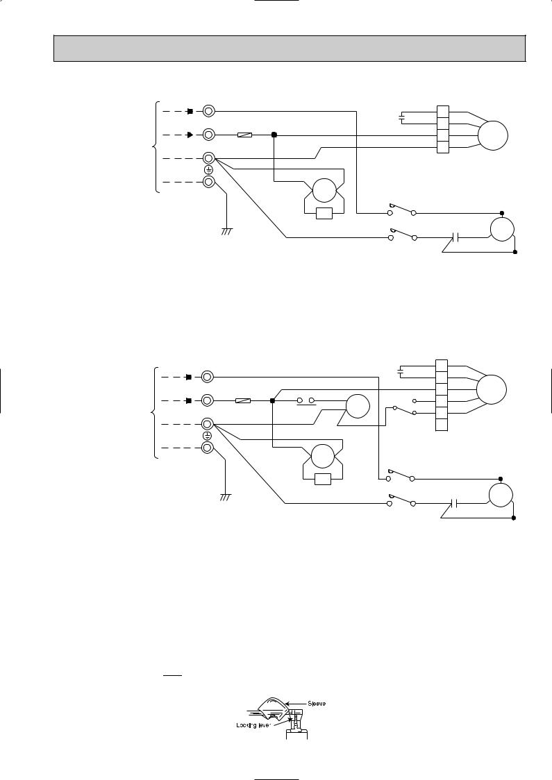
SU-1.6VR.TH SU-1.6VR2.TH SU-2VR.TH SU-2VR1.TH SU-1.6VR.TH-T SU-2VR.TH-T
TO INDOOR UNIT CONNECTING
TB
220-240V,50Hz 2 W
220-240V,50Hz 3 WRED F
N W
GRN/YLW
WHT |
|
|
|
RED |
1 |
RED |
|
|
|
C2 |
ORN |
ORN |
|
|
|
|
2 |
|||
RED TB2 |
|
|
|
WHT |
WHT |
|
|
|
|
3 |
|||
|
|
|
|
BLU |
MF |
|
|
|
|
|
4 |
BLK |
|
|
|
|
|
|
|
|
|
BLU |
|
|
|
|
|
WHT |
|
|
|
|
|
|
A1 |
52C |
A2 |
52C |
|
|
|
|
|
|
|
WHT |
||
|
CR |
|
|
|
|
|
VLT |
YLW |
L1/1 |
T1/2 |
|
C |
|
|
BLU |
|
|
BLU C1 WRED S MC R |
||
|
|
|
L3/5 |
T3/6 |
W |
W BLK |
|
|
|
|
|||
SYMBOL |
NAME |
SYMBOL |
NAME |
SYMBOL |
NAME |
|
|
|
|
|
|
|
|
CR |
SURGE ABSORBER |
MC |
COMPRESSOR |
52C |
COMPRESSOR CONTACTOR |
|
(INNER THERMOSTAT) |
||||||
|
|
|
|
|
||
C1 |
COMPRESSOR CAPACITOR |
MF |
FAN MOTOR |
|
|
|
(INNER THERMOSTAT) |
|
|
||||
|
|
|
|
|
||
C2 |
FAN MOTOR CAPACITOR |
TB |
TERMINAL BLOCK |
|
|
|
|
|
|
|
|
|
|
F |
FUSE(2A) |
TB2 |
TERMINAL BLOCK |
|
|
|
|
|
|
|
|
|
SU-2.5VR.TH SU-2.5VR.TH-T
CONNECTING
UNIT
TO INDOOR
TB
220-240V,50Hz 2 W
220-240V,50Hz 3 W RED F
N W
GRN/YLW
|
|
|
|
|
RED |
1 |
RED |
|
|
WHT |
|
|
|
C2 |
ORN |
ORN |
|
|
|
|
|
|
2 |
|
|
||||
|
|
|
|
|
WHT |
WHT |
|
|
|
|
|
|
|
|
3 |
MF |
|
||
RED RED |
|
RED8 |
|
3 BLK |
BLK |
|
|||
|
5 |
4 |
|
|
|||||
TB2 |
|
BLU 7 |
YLW |
YLW |
|
|
|||
26F1 |
X1 |
5 |
|
|
|||||
|
|
|
|
X1 |
|
|
|
||
|
|
|
|
ORN |
1 |
6 |
|
|
|
|
|
|
|
|
|
|
|
|
|
WHT |
|
BLU |
|
|
|
|
|
|
|
|
|
|
|
|
|
|
|
|
|
|
A1 |
52C |
A2 |
52C |
|
|
|
|
|
|
|
|
|
|
WHT |
|
|
||
|
|
|
|
|
|
|
|
|
|
|
VLT |
CR |
YLW |
L1/1 |
T1/2 |
|
|
C |
|
|
|
BLU |
|
|
BLU |
C1 |
RED S |
MC |
R |
|
|
|
|
|
|||||
|
|
|
|
L3/5 |
T3/6 |
|
BLK |
|
|
SYMBOL |
NAME |
SYMBOL |
NAME |
SYMBOL |
NAME |
|
|
|
|
|
|
|
|
CR |
SURGE ABSORBER |
MC |
COMPRESSOR |
X1 |
FAN MOTOR RELAY |
|
(INNER THERMOSTAT) |
||||||
|
|
|
|
|
||
|
|
|
|
|
|
|
C1 |
COMPRESSOR CAPACITOR |
MF |
FAN MOTOR |
26F1 |
THERMAL LEAD SWITCH |
|
(INNER THERMOSTAT) |
||||||
|
|
|
|
|
||
|
|
|
|
|
|
|
C2 |
FAN MOTOR CAPACITOR |
TB |
TERMINAL BLOCK |
52C |
COMPRESSOR CONTACTOR |
|
|
|
|
|
|
|
|
F |
FUSE(2A) |
TB2 |
TERMINAL BLOCK |
|
|
|
|
|
|
|
|
|
NOTE :1. Use copper conductors only. (For field wiring)
2.Since the indoor and outdoor unit connecting wires have polarity, connect them according to the numbers (N,2,3 and ;).
3.Symbols below indicate.
/:Terminal block,  : Connector
4.”w” shows the terminals with a lock mechanism,so they cannot be removed when you pull the lead wire. Be sure to pull the wire by pushing the locking lever (projected part) of the terminal with a finger.
1Slide the sleeve.
2Pull the wire while pushing the locking lever.
17
 Loading...