


 Loading...
Mitsubishi RJ71C24, RJ71C24-R2, RJ71C24-R4, RJ71EN71, R04ENCPU Reference Manual
...MELSEC iQ-R MODBUS and MODBUS/TCP
Reference Manual
-RJ71C24 -RJ71C24-R2 -RJ71C24-R4 -RJ71EN71 -R04ENCPU -R08ENCPU -R16ENCPU -R32ENCPU -R120ENCPU

SAFETY PRECAUTIONS
(Read these precautions before using this product.)
Before using MELSEC iQ-R series programmable controllers, please read the manuals for the product and the relevant manuals introduced in those manuals carefully, and pay full attention to safety to handle the product correctly.
Make sure that the end users read this manual and then keep the manual in a safe place for future reference.
CONDITIONS OF USE FOR THE PRODUCT
(1)MELSEC programmable controller ("the PRODUCT") shall be used in conditions;
i)where any problem, fault or failure occurring in the PRODUCT, if any, shall not lead to any major or serious accident; and
ii)where the backup and fail-safe function are systematically or automatically provided outside of the PRODUCT for the case of any problem, fault or failure occurring in the PRODUCT.
(2)The PRODUCT has been designed and manufactured for the purpose of being used in general industries. MITSUBISHI ELECTRIC SHALL HAVE NO RESPONSIBILITY OR LIABILITY (INCLUDING, BUT NOT LIMITED TO ANY AND ALL RESPONSIBILITY OR LIABILITY BASED ON CONTRACT, WARRANTY, TORT, PRODUCT LIABILITY) FOR ANY INJURY OR DEATH TO PERSONS OR LOSS OR DAMAGE TO PROPERTY CAUSED BY the PRODUCT THAT ARE OPERATED OR USED IN APPLICATION NOT INTENDED OR EXCLUDED BY INSTRUCTIONS, PRECAUTIONS, OR WARNING CONTAINED IN MITSUBISHI ELECTRIC USER'S, INSTRUCTION AND/OR SAFETY MANUALS, TECHNICAL BULLETINS AND GUIDELINES FOR the PRODUCT.
("Prohibited Application")
Prohibited Applications include, but not limited to, the use of the PRODUCT in;
•Nuclear Power Plants and any other power plants operated by Power companies, and/or any other cases in which the public could be affected if any problem or fault occurs in the PRODUCT.
•Railway companies or Public service purposes, and/or any other cases in which establishment of a special quality assurance system is required by the Purchaser or End User.
•Aircraft or Aerospace, Medical applications, Train equipment, transport equipment such as Elevator and Escalator, Incineration and Fuel devices, Vehicles, Manned transportation, Equipment for Recreation and Amusement, and
Safety devices, handling of Nuclear or Hazardous Materials or Chemicals, Mining and Drilling, and/or other applications where there is a significant risk of injury to the public or property.
Notwithstanding the above restrictions, Mitsubishi Electric may in its sole discretion, authorize use of the PRODUCT in one or more of the Prohibited Applications, provided that the usage of the PRODUCT is limited only for the specific applications agreed to by Mitsubishi Electric and provided further that no special quality assurance or fail-safe, redundant or other safety features which exceed the general specifications of the PRODUCTs are required. For details, please contact the Mitsubishi Electric representative in your region.
(3)Mitsubishi Electric shall have no responsibility or liability for any problems involving programmable controller trouble and system trouble caused by DoS attacks, unauthorized access, computer viruses, and other cyberattacks.
1

INTRODUCTION
Thank you for purchasing the Mitsubishi Electric MELSEC iQ-R series programmable controllers.
This manual describes the frame specifications and MODBUS standard functions to use the MODBUS slave function and MODBUS/TCP slave function of the following modules.
Before using this product, please read this manual and the relevant manuals carefully and develop familiarity with the functions and performance of the MELSEC iQ-R series programmable controller to handle the product correctly.
Relevant products
RJ71C24, RJ71C24-R2, RJ71C24-R4
RJ71EN71, R04ENCPU, R08ENCPU, R16ENCPU, R32ENCPU, R120ENCPU
2

CONTENTS
SAFETY PRECAUTIONS . . . . . . . . . . . . . . . . . . . . . . . . . . . . . . . . . . . . . . . . . . . . . . . . . . . . . . . . . . . . . . . . . . . .1 CONDITIONS OF USE FOR THE PRODUCT . . . . . . . . . . . . . . . . . . . . . . . . . . . . . . . . . . . . . . . . . . . . . . . . . . . .1 INTRODUCTION. . . . . . . . . . . . . . . . . . . . . . . . . . . . . . . . . . . . . . . . . . . . . . . . . . . . . . . . . . . . . . . . . . . . . . . . . . .2 RELEVANT MANUALS . . . . . . . . . . . . . . . . . . . . . . . . . . . . . . . . . . . . . . . . . . . . . . . . . . . . . . . . . . . . . . . . . . . . . .5 TERMS . . . . . . . . . . . . . . . . . . . . . . . . . . . . . . . . . . . . . . . . . . . . . . . . . . . . . . . . . . . . . . . . . . . . . . . . . . . . . . . . . .5 GENERIC TERMS AND ABBREVIATIONS. . . . . . . . . . . . . . . . . . . . . . . . . . . . . . . . . . . . . . . . . . . . . . . . . . . . . . .5
CHAPTER 1 FRAME SPECIFICATIONS |
6 |
1.1 MODBUS Protocol Frame Specifications . . . . . . . . . . . . . . . . . . . . . . . . . . . . . . . . . . . . . . . . . . . . . . . . . . . . . 6
RTU mode . . . . . . . . . . . . . . . . . . . . . . . . . . . . . . . . . . . . . . . . . . . . . . . . . . . . . . . . . . . . . . . . . . . . . . . . . . . . . . . 6 ASCII mode . . . . . . . . . . . . . . . . . . . . . . . . . . . . . . . . . . . . . . . . . . . . . . . . . . . . . . . . . . . . . . . . . . . . . . . . . . . . . . 8
1.2 MODBUS/TCP Protocol Frame Specifications . . . . . . . . . . . . . . . . . . . . . . . . . . . . . . . . . . . . . . . . . . . . . . . . 10 1.3 Protocol Data Unit Formats Grouped by Function. . . . . . . . . . . . . . . . . . . . . . . . . . . . . . . . . . . . . . . . . . . . . 11
CHAPTER 2 |
MODBUS STANDARD FUNCTION LIST |
13 |
CHAPTER 3 |
MODBUS STANDARD FUNCTION DETAILS |
14 |
3.1 Read Coils (FC: 01H). . . . . . . . . . . . . . . . . . . . . . . . . . . . . . . . . . . . . . . . . . . . . . . . . . . . . . . . . . . . . . . . . . . . . 14 3.2 Read Discrete Inputs (FC: 02H) . . . . . . . . . . . . . . . . . . . . . . . . . . . . . . . . . . . . . . . . . . . . . . . . . . . . . . . . . . . . 15 3.3 Read Holding Registers (FC: 03H) . . . . . . . . . . . . . . . . . . . . . . . . . . . . . . . . . . . . . . . . . . . . . . . . . . . . . . . . . . 16 3.4 Read Input Registers (FC: 04H) . . . . . . . . . . . . . . . . . . . . . . . . . . . . . . . . . . . . . . . . . . . . . . . . . . . . . . . . . . . . 17 3.5 Write Single Coil (FC: 05H) . . . . . . . . . . . . . . . . . . . . . . . . . . . . . . . . . . . . . . . . . . . . . . . . . . . . . . . . . . . . . . . . 18 3.6 Write Single Register (FC: 06H) . . . . . . . . . . . . . . . . . . . . . . . . . . . . . . . . . . . . . . . . . . . . . . . . . . . . . . . . . . . . 19 3.7 Read Exception Status (FC: 07H). . . . . . . . . . . . . . . . . . . . . . . . . . . . . . . . . . . . . . . . . . . . . . . . . . . . . . . . . . . 20 3.8 Diagnostics (FC: 08H) . . . . . . . . . . . . . . . . . . . . . . . . . . . . . . . . . . . . . . . . . . . . . . . . . . . . . . . . . . . . . . . . . . . . 21
Return query data (sub-function code: 00H) . . . . . . . . . . . . . . . . . . . . . . . . . . . . . . . . . . . . . . . . . . . . . . . . . . . . 22 Restart communications option (sub-function code: 01H). . . . . . . . . . . . . . . . . . . . . . . . . . . . . . . . . . . . . . . . . . 23 Return diagnostic register (sub-function code: 02H) . . . . . . . . . . . . . . . . . . . . . . . . . . . . . . . . . . . . . . . . . . . . . . 24 Change ASCII input delimiter (sub-function code: 03H) . . . . . . . . . . . . . . . . . . . . . . . . . . . . . . . . . . . . . . . . . . . 25 Force listen only mode (sub-function code: 04H) . . . . . . . . . . . . . . . . . . . . . . . . . . . . . . . . . . . . . . . . . . . . . . . . 26 Clear counters and diagnostic register (sub-function code: 0AH) . . . . . . . . . . . . . . . . . . . . . . . . . . . . . . . . . . . . 27 Return bus message count (sub-function code: 0BH). . . . . . . . . . . . . . . . . . . . . . . . . . . . . . . . . . . . . . . . . . . . . 28 Return bus communication error count (sub-function code: 0CH) . . . . . . . . . . . . . . . . . . . . . . . . . . . . . . . . . . . 29 Return bus exception error count (sub-function code: 0DH) . . . . . . . . . . . . . . . . . . . . . . . . . . . . . . . . . . . . . . . . 30 Return slave message count (sub-function code: 0EH) . . . . . . . . . . . . . . . . . . . . . . . . . . . . . . . . . . . . . . . . . . . 31 Return slave no response count (sub-function code: 0FH) . . . . . . . . . . . . . . . . . . . . . . . . . . . . . . . . . . . . . . . . . 32 Return slave NAK count (sub-function code: 10H) . . . . . . . . . . . . . . . . . . . . . . . . . . . . . . . . . . . . . . . . . . . . . . . 33 Return slave busy count (sub-function code: 11H) . . . . . . . . . . . . . . . . . . . . . . . . . . . . . . . . . . . . . . . . . . . . . . . 34 Return bus character overrun count (sub-function code: 12H) . . . . . . . . . . . . . . . . . . . . . . . . . . . . . . . . . . . . . . 35 Return IOP overrun error count (sub-function code: 13H). . . . . . . . . . . . . . . . . . . . . . . . . . . . . . . . . . . . . . . . . . 36 Clear overrun counter and flag (sub-function code: 14H) . . . . . . . . . . . . . . . . . . . . . . . . . . . . . . . . . . . . . . . . . . 37
3.9 Get Communications Event Counter (FC: 0BH) . . . . . . . . . . . . . . . . . . . . . . . . . . . . . . . . . . . . . . . . . . . . . . . 38 3.10 Get Communications Event Log (FC: 0CH) . . . . . . . . . . . . . . . . . . . . . . . . . . . . . . . . . . . . . . . . . . . . . . . . . . 39 3.11 Write Multiple Coils (FC: 0FH) . . . . . . . . . . . . . . . . . . . . . . . . . . . . . . . . . . . . . . . . . . . . . . . . . . . . . . . . . . . . . 41 3.12 Write Multiple Registers (FC: 10H). . . . . . . . . . . . . . . . . . . . . . . . . . . . . . . . . . . . . . . . . . . . . . . . . . . . . . . . . . 42 3.13 Report Slave ID (FC: 11H) . . . . . . . . . . . . . . . . . . . . . . . . . . . . . . . . . . . . . . . . . . . . . . . . . . . . . . . . . . . . . . . . . 43 3.14 Read File Record (FC: 14H) (SC: 06H). . . . . . . . . . . . . . . . . . . . . . . . . . . . . . . . . . . . . . . . . . . . . . . . . . . . . . . 45 3.15 Write File Record (FC: 15H) (SC: 06H). . . . . . . . . . . . . . . . . . . . . . . . . . . . . . . . . . . . . . . . . . . . . . . . . . . . . . . 47
<![endif]>CONTENTS
3

3.16 Mask Write Register (FC: 16H) . . . . . . . . . . . . . . . . . . . . . . . . . . . . . . . . . . . . . . . . . . . . . . . . . . . . . . . . . . . . . 48 3.17 Read/Write Multiple Registers (FC: 17H). . . . . . . . . . . . . . . . . . . . . . . . . . . . . . . . . . . . . . . . . . . . . . . . . . . . . 49
CHAPTER 4 EXCEPTION CODES |
50 |
INDEX |
52 |
REVISIONS. . . . . . . . . . . . . . . . . . . . . . . . . . . . . . . . . . . . . . . . . . . . . . . . . . . . . . . . . . . . . . . . . . . . . . . . . . . . . .54 WARRANTY . . . . . . . . . . . . . . . . . . . . . . . . . . . . . . . . . . . . . . . . . . . . . . . . . . . . . . . . . . . . . . . . . . . . . . . . . . . . .55 TRADEMARKS . . . . . . . . . . . . . . . . . . . . . . . . . . . . . . . . . . . . . . . . . . . . . . . . . . . . . . . . . . . . . . . . . . . . . . . . . . .56
4

RELEVANT MANUALS
Manual name [manual number] |
Description |
Available form |
MELSEC iQ-R MODBUS and MODBUS/TCP |
Protocol (MODBUS, MODBUS/TCP) that reads and writes data from a target |
e-Manual |
Reference Manual |
device to a module |
|
[BCN-P5999-1060] (this manual) |
|
|
|
|
|
e-Manual refers to the Mitsubishi Electric FA electronic book manuals that can be browsed using a dedicated tool.
e-Manual has the following features:
•Required information can be cross-searched in multiple manuals.
•Other manuals can be accessed from the links in the manual.
•The hardware specifications of each part can be found from the product figures.
•Pages that users often browse can be bookmarked.
•Sample programs can be copied to an engineering tool.
TERMS
Unless otherwise specified, this manual uses the following terms.
Term |
Description |
Master |
A name for the side that requests function execution |
|
|
MODBUS device |
A device used in communications via the MODBUS protocol |
|
|
Request message |
A message that requests function execution to slaves. |
|
In the MODBUS protocol, the master requests function execution to the slaves. |
|
|
Response message |
A message that returns execution results of functions from a slave to the master |
|
|
Slave |
A name for the side that processes execution requests from the master and returns the execution results |
|
|
GENERIC TERMS AND ABBREVIATIONS
Unless otherwise specified, this manual uses the following generic terms and abbreviations.
Generic term/abbreviation |
Description |
C24 |
A MELSEC iQ-R series serial communication module |
|
|
FC |
An abbreviation of function code |
|
|
SC |
An abbreviation of sub code |
|
|
5

1 FRAME SPECIFICATIONS
1.1 MODBUS Protocol Frame Specifications
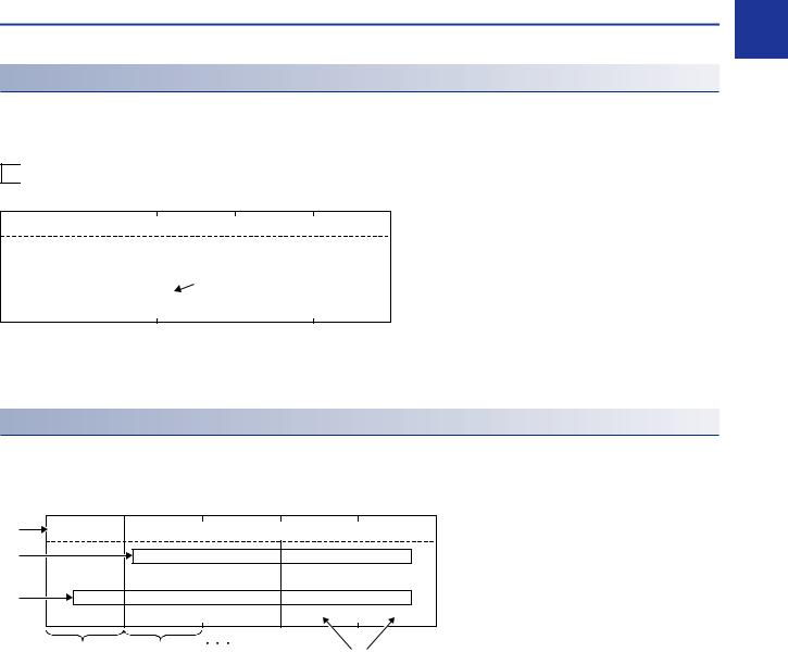
This section describes the frame specifications of the MODBUS protocol.
|
Address field |
|
|
Function code |
|
|
Data |
Error check |
|
|
|
|
|
|
|
|
|
|
|
|
|
|
|
|
|
|
|
|
|
|
||
|
|
|
|
|
Protocol data unit |
|
|
|||
|
|
|
|
|
|
|
|
|
|
|
|
Area name |
|
|
|
|
Description |
|
|
||
|
Address field |
|
|
|
|
■When request message is sent from the master to a slave |
||||
|
|
|
|
|
|
• 0: Sends a request message to all the slaves. (Broadcast) |
||||
|
|
|
|
|
|
• 1 to 247: Stores the target slave station number. |
||||
|
|
|
|
|
|
■When response message is sent from a slave to the master |
||||
|
|
|
|
|
|
The host station number is stored when sending a response message. |
||||
|
|
|
|
|
|
|
|
|
|
|
|
Protocol data unit |
|
Function code |
|
■When request message is sent from the master to a slave |
|||||
|
|
|
|
|
|
Specifies the content of the processing instructed from the master to a slave. |
||||
|
|
|
|
|
|
■When response message is sent from a slave to the master |
||||
|
|
|
|
|
|
A requested function code is stored in the case of normal completion. |
||||
|
|
|
|
|
|
The most significant bit turns ON in the case of error completion. |
||||
|
|
|
|
|
|
|
|
|
|
|
|
|
Data |
|
■When request message is sent from the master to a slave |
||||||
|
|
|
|
|
|
Stores the request content of the processing. |
||||
|
|
|
|
|
|
■When response message is sent from a slave to the master |
||||
|
|
|
|
|
|
Stores the execution result of the processing. |
||||
|
|
|
|
|
|
|
|
|
|
|
|
Error check |
|
|
|
|
The master adds a check code in a request message and transmits the request message. |
||||
|
|
|
|
|
|
The slave, which received the request message, recalculates the check code in the request message |
||||
|
|
|
|
|
|
and determines whether the message is correct or not. |
||||
|
|
|
|
|
|
The message is discarded if it has an error. |
||||
|
|
|
|
|
|
The error check method differs depending on the frame mode. |
||||
|
|
|
|
|
|
|
|
|
|
|
The following frame modes are available.
•RTU mode
•ASCII mode
The frame mode of C24 must be consistent with that of the target device.
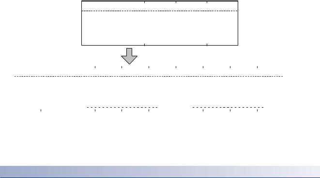
RTU mode
In this mode, frames are received or sent in binary codes.
The frame specifications are compliant with the MODBUS protocol specifications.
Start |
Address field |
Function code |
Data |
Error check |
END |
Address field |
|
(Start) |
|||||||
|
|
|
|
|
|
||
3.5 character time |
1 byte |
1 byte |
0 to 252 bytes |
2 bytes |
3.5 character time |
1 byte |
|
or more |
or more |
||||||
|
|
|
|
|
Error check calculation range
Error check in RTU mode
The error check in the RTU mode is conducted by CRC (Cyclic Redundancy Check). C24 calculates the CRC by the following steps.
Follow the same steps to calculate the CRC when conducting an error check on the target device.
1.
2. The CRC is calculated every 8 bits from the upper bit of the frame.
Calculate the exclusive OR (XOR) from the 8 bits of the frame and the bits of the step 1.
3. Shift the result of step 2 by 1 bit to the right.
6 |
1 FRAME SPECIFICATIONS |
1.1 MODBUS Protocol Frame Specifications |

4. |
If the least significant bit of the step 2 is '1', calculate the exclusive OR (XOR) from the result of step 3 and the generator |
|
|
|
polynomial (A001H). |
|
|
|
1 |
||
If the least significant bit is '0', do not calculate the exclusive OR (XOR), but shift it by 1 bit to the right. |
|||
5. |
Repeat the step 3 and 4 until the bit is shifted up to 8 times. |
||
|
|||
6. |
Calculate the exclusive OR (XOR) from the result of step 5 and the next 8 bits of the frame. |
|
|
7. |
Repeat the step 3 to 6. |
|
|
8. |
Repeat the above operations until the end of the data unit is reached. The final value is a calculated CRC value. |
|
|
9. |
The CRC value is stored in the frame in the order of lower 8 bits to upper 8 bits. |
|
|
Ex.
The following is a calculation example in the case where function code 07H is sent to station No.2.
Error check range is as follows:
•Address field (1 byte): 02H
•Function code (1 byte): 07H
•Data (0 bytes)
CRC error checking procedure |
16-bit register (MSB) |
|
|
Flag*1 |
|
1 |
Load the 16-bit register whose bits are all '1'. |
16-bit register whose bits are all '1'. |
1111 1111 |
1111 1111 |
|
|
|
|
|
|
|
2 |
Calculate the exclusive OR (XOR) from the first 8 bits of the |
Address field (02H) |
|
0000 0010 |
|
|
frame and the bits in the above. |
|
|
|
|
|
Exclusive OR (XOR) |
1111 1111 |
1111 1101 |
|
|
|
|
|
|||
|
|
|
|
|
|
3 |
Shift by 1 bit to the right. |
Shift 1 |
0111 1111 |
1111 1110 |
1 |
|
|
|
|
|
|
4 |
Since the flag is '1', calculate the exclusive OR (XOR) from the |
Generator polynomial (A001H) |
1010 0000 |
0000 0001 |
|
|
result in 'Shift 1' and generator polynomial (A001H). |
|
|
|
|
|
Exclusive OR (XOR) |
1101 1111 |
1111 1111 |
|
|
|
|
|
|||
|
|
|
|
|
|
5 |
Shift by 1 bit to the right. |
Shift 2 |
0110 1111 |
1111 1111 |
1 |
|
|
|
|
|
|
|
Since the flag is '1', calculate the exclusive OR (XOR) from the |
Generator polynomial (A001H) |
1010 0000 |
0000 0001 |
|
|
result in 'Shift 2' and generator polynomial (A001H). |
|
|
|
|
|
Exclusive OR (XOR) |
1100 1111 |
1111 1110 |
|
|
|
|
|
|||
|
|
|
|
|
|
|
Shift by 1 bit to the right. |
Shift 3 |
0110 0111 |
1111 1111 |
0 |
|
|
|
|
|
|
|
Shift by 1 bit to the right. |
Shift 4 |
0011 0011 |
1111 1111 |
1 |
|
|
|
|
|
|
|
Since the flag is '1', calculate the exclusive OR (XOR) from the |
Generator polynomial (A001H) |
1010 0000 |
0000 0001 |
|
|
result in 'Shift 4' and generator polynomial (A001H). |
|
|
|
|
|
Exclusive OR (XOR) |
1001 0011 |
1111 1110 |
|
|
|
|
|
|||
|
|
|
|
|
|
|
Shift by 1 bit to the right. |
Shift 5 |
0100 1001 |
1111 1111 |
0 |
|
|
|
|
|
|
|
Shift by 1 bit to the right. |
Shift 6 |
0010 0100 |
1111 1111 |
1 |
|
|
|
|
|
|
|
Since the flag is '1', calculate the exclusive OR (XOR) from the |
Generator polynomial (A001H) |
1010 0000 |
0000 0001 |
|
|
result in 'Shift 6' and generator polynomial (A001H). |
|
|
|
|
|
Exclusive OR (XOR) |
1000 0100 |
1111 1110 |
|
|
|
|
|
|||
|
|
|
|
|
|
|
Shift by 1 bit to the right. |
Shift 7 |
0100 0010 |
0111 1111 |
0 |
|
|
|
|
|
|
|
Shift by 1 bit to the right. |
Shift 8 |
0010 0001 |
0011 1111 |
1 |
|
|
|
|
|
|
|
Since the flag is '1', calculate the exclusive OR (XOR) from the |
Generator polynomial (A001H) |
1010 0000 |
0000 0001 |
|
|
result in 'Shift 8' and generator polynomial (A001H). |
|
|
|
|
|
Exclusive OR (XOR) |
1000 0001 |
0011 1110 |
|
|
|
|
|
|||
|
|
|
|
|
|
6 |
Calculate the exclusive OR (XOR) from the next 8 bits of the |
Function code (07H) |
|
0000 0111 |
|
|
frame and the bits in the above. |
|
|
|
|
|
Exclusive OR (XOR) |
1000 0001 |
0011 1001 |
|
|
|
|
|
|||
|
|
|
|
|
|
1 FRAME SPECIFICATIONS |
7 |
1.1 MODBUS Protocol Frame Specifications |

CRC error checking procedure |
16-bit register (MSB) |
|
|
Flag*1 |
|
7 |
Shift by 1 bit to the right. |
Shift 1 |
0100 0000 |
1001 1100 |
1 |
|
|
|
|
|
|
|
Since the flag is '1', calculate the exclusive OR (XOR) from the |
Generator polynomial (A001H) |
1010 0000 |
0000 0001 |
|
|
result in 'Shift 1' and generator polynomial (A001H). |
|
|
|
|
|
Exclusive OR (XOR) |
1110 0000 |
1001 1101 |
|
|
|
|
|
|||
|
|
|
|
|
|
|
Shift by 1 bit to the right. |
Shift 2 |
0111 0000 |
0100 1110 |
1 |
|
|
|
|
|
|
|
Since the flag is '1', calculate the exclusive OR (XOR) from the |
Generator polynomial (A001H) |
1010 0000 |
0000 0001 |
|
|
result in 'Shift 2' and generator polynomial (A001H). |
|
|
|
|
|
Exclusive OR (XOR) |
1101 0000 |
0100 1111 |
|
|
|
|
|
|||
|
|
|
|
|
|
|
Shift by 1 bit to the right. |
Shift 3 |
0110 1000 |
0010 0111 |
1 |
|
|
|
|
|
|
|
Since the flag is '1', calculate the exclusive OR (XOR) from the |
Generator polynomial (A001H) |
1010 0000 |
0000 0001 |
|
|
result in 'Shift 3' and generator polynomial (A001H). |
|
|
|
|
|
Exclusive OR (XOR) |
1100 1000 |
0010 1110 |
|
|
|
|
|
|||
|
|
|
|
|
|
|
Shift by 1 bit to the right. |
Shift 4 |
0110 0100 |
0001 0011 |
0 |
|
|
|
|
|
|
|
Shift by 1 bit to the right. |
Shift 5 |
0011 0010 |
0000 1001 |
1 |
|
|
|
|
|
|
|
Since the flag is '1', calculate the exclusive OR (XOR) from the |
Generator polynomial (A001H) |
1010 0000 |
0000 0001 |
|
|
result in 'Shift 5' and generator polynomial (A001H). |
|
|
|
|
|
Exclusive OR (XOR) |
1001 0010 |
0000 1000 |
|
|
|
|
|
|||
|
|
|
|
|
|
|
Shift by 1 bit to the right. |
Shift 6 |
0100 1001 |
0000 0100 |
0 |
|
|
|
|
|
|
|
Shift by 1 bit to the right. |
Shift 7 |
0010 0100 |
1000 0010 |
0 |
|
|
|
|
|
|
|
Shift by 1 bit to the right. |
Shift 8 |
0001 0010 |
0100 0001 |
0 |
|
|
|
|
|
|
8 |
The final value is a calculated CRC value. |
CRC value |
12H |
41H |
|
|
|
|
|
|
|
*1 The least significant bit from the previous exclusive OR (XOR)
Data is stored as follows:
Address field |
Function code |
Error check |
|
|
|
Lower 8 bits of the CRC value |
Upper 8 bits of the CRC value |
02H |
07H |
41H |
12H |
|
|
|
|
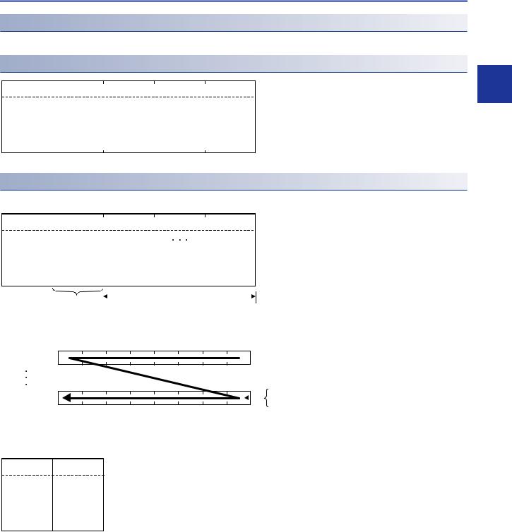
ASCII mode
In this mode, frames are received or sent in units of 2 characters (2 bytes) in ASCII codes.
The frame specifications are compliant with the MODBUS protocol specifications.
Start |
Address field |
Function code |
|
Data |
Error check |
END |
||
: |
2 characters |
2 characters |
|
n x 2 characters |
2 characters |
CR + LF |
||
(3AH) |
|
(n = 0 to 252) |
(0DH) (0AH) |
|||||
|
|
|
|
|
|
|||
|
|
|
|
|
|
|
|
|
|
|
|
|
|
|
|
|
|
|
|
Error check calculation range |
|
|
|
|
||
|
|
|
|
|
|
|||
|
|
|
|
|
|
|
|
|
Error check in ASCII mode
The error check in the ASCII mode is conducted by LRC (Longitudinal Redundancy Check). C24 calculates the LRC by the following steps.
Follow the same steps to calculate the LRC when conducting an error check on the target device.
1.
2.
3.
4.
To calculate the LRC, convert the ASCII codes within the error check range into the RTU format (binary).
Add the figures in units of contiguous 8 bits in the frame. (Excluding carries during addition.)
Change the result of step 2 to a 2's complement. (Reverse the bits and add 01H.)
Convert the result of step 3 to an ASCII code.
Ex.
The following are calculation examples in the case where function code 01H is sent to station No.2. Error check range of the request message is as follows:
•Address field (1 byte): 02H
•Function code (1 byte): 01H
8 |
1 FRAME SPECIFICATIONS |
1.1 MODBUS Protocol Frame Specifications |
• Data (2 bytes): Start coil number specification (0000H), Number of read points (0008H)
Error check procedure |
LRC in request message transmission |
|
|
|
|
||
|
|
|
1 |
||||
1 |
Convert the ASCII codes within the error check range into the RTU format |
Address field (02H) |
0000 |
0010 |
|
||
|
(binary). |
|
|
|
|
|
|
|
Function code (01H) |
0000 |
0001 |
|
|||
|
|
|
|
||||
|
|
|
|
|
|
|
|
|
|
Start coil number specification (H) |
0000 |
0000 |
|
|
|
|
|
|
|
|
|
|
|
|
|
Start coil number specification (L) |
0000 |
0000 |
|
|
|
|
|
|
|
|
|
|
|
|
|
Read points (H) |
0000 |
0000 |
|
|
|
|
|
|
|
|
|
|
|
|
|
Read points (L) |
0000 |
1000 |
|
|
|
|
|
|
|
|
|
|
|
2 |
Add the figures. (Excluding carries during addition.) |
Addition result |
0000 |
1011 |
|
|
|
|
|
|
|
|
|
|
|
3 |
Change the result to a 2's complement. (Reverse the bits and add 01H.) |
Reversed bit value |
1111 |
0100 |
|
|
|
|
|
|
|
|
|
|
|
|
|
01H |
0000 |
0001 |
|
|
|
|
|
|
|
|
|
|
|
|
|
LRC value |
1111 |
0101 |
|
|
|
|
|
|
|
|
|
|
|
4 |
Convert the result to an ASCII code. |
LRC value (ASCII code) |
F |
5 |
|
|
|
|
|
|
|
|
|
|
|
|
|
|
|
46H |
35H |
|
|
|
|
|
|
|
|
|
|
Data is stored in ASCII code as follows:
Data |
Address field |
Function code |
Start coil number |
|
Read points |
|
|
Error check |
||||||
category |
|
|
|
|
specification |
|
|
|
|
|
|
|
|
|
Value |
02H |
|
01H |
|
0000H |
|
|
|
0008H |
|
|
|
F5H |
|
|
|
|
|
|
|
|
|
|
|
|
|
|
|
|
Character |
0 |
2 |
0 |
1 |
0 |
0 |
0 |
0 |
0 |
0 |
0 |
8 |
F |
5 |
|
|
|
|
|
|
|
|
|
|
|
|
|
|
|
RTU (binary) |
0000 |
0010 |
0000 |
0001 |
0000 |
0000 |
0000 |
0000 |
0000 |
0000 |
0000 |
1000 |
1111 |
0101 |
|
|
|
|
|
|
|
|
|
|
|
|
|
|
|
ASCII code |
30H |
32H |
30H |
31H |
30H |
30H |
30H |
30H |
30H |
30H |
30H |
38H |
46H |
35H |
|
|
|
|
|
|
|
|
|
|
|
|
|
|
|
The slave, which received the request message, recalculates the check code in the request message and determines whether the message is correct or not.
Error check procedure |
LRC check when receiving a request message |
|
||
1 |
Convert the ASCII codes within the error check range into the RTU format |
Address field (02H) |
0000 |
0010 |
|
(binary). |
|
|
|
|
Function code (01H) |
0000 |
0001 |
|
|
|
|||
|
|
|
|
|
|
|
Start coil number specification (H) |
0000 |
0000 |
|
|
|
|
|
|
|
Start coil number specification (L) |
0000 |
0000 |
|
|
|
|
|
|
|
Read points (H) |
0000 |
0000 |
|
|
|
|
|
|
|
Read points (L) |
0000 |
1000 |
|
|
|
|
|
2 |
Add the LRC value. (Excluding carries during addition.) |
LRC value |
1111 |
0101 |
|
Normally, the addition result is zero. |
|
|
|
|
Addition result |
0000 |
0000 |
|
|
|
|||
|
|
|
|
|
1 FRAME SPECIFICATIONS |
9 |
1.1 MODBUS Protocol Frame Specifications |

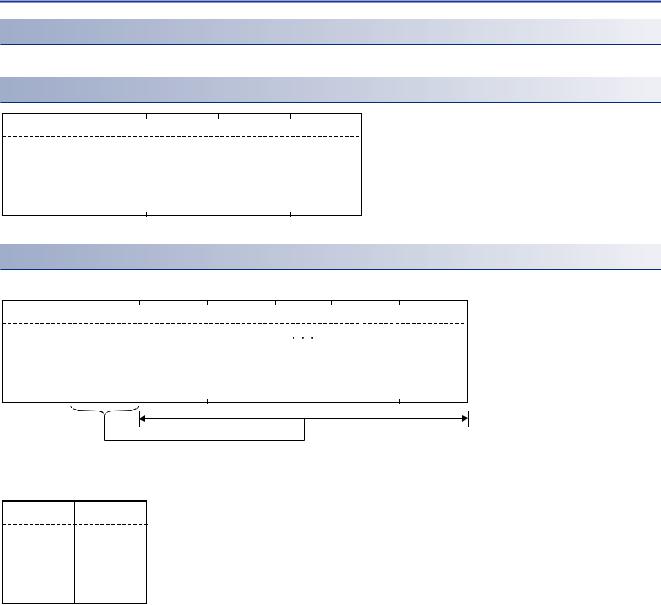
1.2 MODBUS/TCP Protocol Frame Specifications
This section describes the frame specifications of the MODBUS/TCP protocol.
MODBUS/TCP frame |
Ethernet |
IP header |
TCP header |
|
Application data |
|
|
FCS |
||
header |
|
|
|
|
|
|
|
|
(Error check) |
|
|
|
|
|
|
|
|
|
|
||
|
|
|
|
|
|
MODBUS/TCP application data unit |
||||
|
MODBUS application header |
|
|
|
|
Protocol data unit |
|
|
|
|
|
|
|
|
|
|
|
|
|||
|
|
|
|
|
|
|
|
|
|
|
|
|
|
|
|
|
|
|
|
|
|
|
Transaction |
Protocol ID |
Message |
|
Module ID |
Function code |
Data |
|||
|
ID |
|
length |
|
|
|
|
|
|
|
|
|
|
|
|
|
|
|
|
|
|
|
|
|
|
|
|
|
|
|
|
|
|
|
|
|
|
|
|
|
|
|
|
|
|
|
|
|
|
|
|
|
|
|
Area name |
|
Area size |
Description |
MODBUS application header |
Communication ID |
2 bytes |
Used by the master to match response messages from slaves. |
|
|
|
|
|
Protocol ID |
2 bytes |
Indicates the protocol of the protocol data unit. |
|
|
|
For MODBUS/TCP, 0 is stored. |
|
|
|
|
|
Message length |
2 bytes |
Stores the message size in bytes. |
|
|
|
The stored message length indicates the length of the message in |
|
|
|
areas subsequent to this area. |
|
|
|
|
|
Module ID |
1 byte |
Used when specifying slaves connected to other lines, such as with |
|
|
|
the MODBUS Serial protocol. |
|
|
|
|
Protocol data unit |
Function code |
1 byte |
Specifies the content of the processing instructed from the master to a |
|
|
|
slave. |
|
|
|
|
|
Data |
1 to 252 bytes |
■When request message is sent from the master to a slave |
|
|
|
Stores the request content of the processing. |
|
|
|
■When response message is sent from a slave to the master |
|
|
|
Stores the execution result of the processing. |
|
|
|
|
10 |
1 FRAME SPECIFICATIONS |
1.2 MODBUS/TCP Protocol Frame Specifications |
1.3 Protocol Data Unit Formats Grouped by Function
1
This section describes the protocol data unit formats of the MODBUS standard functions.
When the device number is specified within the message
When specifying the device number within the message, specify "device number - 1".
However, this instruction is not applicable to the file number and the device number specified for reading or writing extended file register.
Ex.
When the status of input 32 (100032) is read by the read discrete inputs (function code: 02H)
Function code |
|
Data |
|
|
|
|
|
|
|||
|
Start input number specification |
|
Number of read points |
||
02H |
|
(1) |
|
|
0001H |
|
001FH |
|
|
||
|
(H) |
(L) |
|
(H) |
(L) |
|
|
|
|
|
|
(1) When reading the status of input 32 (100032), specify 31 (001FH) for the start input number.
The device number stored in the response message is "the device number of the device that actually performed reading/ writing - 1".
Descriptions of request message and response message formats
This section describes descriptions of the request message and response message formats of the MODBUS standard functions.
■ Message format for MODBUS RTU mode and MODBUS/TCP
(1) |
Function code |
|
Data |
|
|
(2) |
|
Start coil number specification |
Number of read points |
||
(3) |
01H |
(0000H to FFFFH) |
(0001H to 07D0H) |
||
|
|
(H) |
(L) |
(H) |
(L) |
1 byte |
1 byte |
(4) |
|
(8 bits) |
(8 bits) |
||
|
(1)Area name
(2)Frame description
(3)For request message format: Setting range
For response message format: Value stored in the response message
(4)When one piece of data consists of two bytes, the upper byte (eight bits) is (H) and the lower byte (eight bits) is (L).
■Message format for MODBUS ASCII mode
The message format shown in Chapter 3 is for RTU mode or MODBUS/TCP.
In the ASCII mode, read the values shown in Chapter 3 in ASCII code.
1 FRAME SPECIFICATIONS |
11 |
1.3 Protocol Data Unit Formats Grouped by Function |
(RTU mode) |
Function code |
|
Data |
|
|
|
|
|
|
|
|||
|
|
|
|
|||
|
|
Start coil number specification |
|
Number of read points |
||
|
01H |
|
(006EH) |
|
|
(003FH) |
|
|
(H) |
(L) |
|
(H) |
(L) |
|
|
|
|
|
|
|
Convert RTU mode to ASCII mode
(ASCII mode)
Function code |
|
|
|
|
Data |
|
|
|
||
|
|
|
Start coil number specification |
|
|
|
Number of read points |
|
||
|
|
|
|
|
|
|
||||
0 |
1 |
0 |
0 |
6 |
E |
|
0 |
0 |
3 |
F |
(30H) |
(31H) |
(30H) |
(30H) |
(36H) |
(45H) |
|
(30H) |
(30H) |
(33H) |
(46H) |
(H) |
(L) |
(H) |
|
|
(L) |
|
(H) |
|
|
(L) |
■ Response message format
The format of the response message sent from a slave to the master varies depending on whether the processing performed by the slave completed successfully or completed with an error.
In the MODBUS standard function, the formats when completed successfully and completed with an error are described in the response message format.
Storage locations of exception code and error code
When processing on a slave is completed with an error, an exception code is sent to the master. For details on exception codes, refer to the following.
Page 50 EXCEPTION CODES
Exception codes are also stored in the buffer memory of modules. The detailed cause is detected as an error by modules.
For details on the buffer memory and errors of modules, refer to the following.MELSEC iQ-R Ethernet User's Manual (Application)
MELSEC iQ-R Serial Communication Module User's Manual(Application)
12 |
1 FRAME SPECIFICATIONS |
1.3 Protocol Data Unit Formats Grouped by Function |

2 |
MODBUS STANDARD FUNCTION LIST |
|
||||||
This chapter lists the MODBUS standard functions and availability for modules when using the slave function. |
||||||||
The modules are abbreviated as follows: |
|
|
|
|
|
|||
|
|
|
|
2 |
||||
• C24: RJ71C24, RJ71C24-R2, RJ71C24-R4 |
|
|
|
|
||||
• E71: RJ71EN71, R04ENCPU, R08ENCPU, R16ENCPU, R32ENCPU, R120ENCPU |
|
|||||||
: Available, : Not available |
|
|
|
|
|
|
||
|
|
|
|
|
|
|
||
Function code |
Sub code (SC) |
Function name |
C24 |
E71 |
Reference |
|||
(FC) |
|
|
|
|
|
|
|
|
01H |
|
|
Read coils |
|
|
Page 14 Read Coils (FC: 01H) |
|
|
|
|
|
|
|
|
|
|
|
02H |
|
|
Read discrete inputs |
|
|
Page 15 Read Discrete Inputs (FC: 02H) |
||
|
|
|
|
|
|
|
|
|
03H |
|
|
Read holding registers |
|
|
Page 16 Read Holding Registers (FC: 03H) |
||
|
|
|
|
|
|
|
|
|
04H |
|
|
Read input registers |
|
|
Page 17 Read Input Registers (FC: 04H) |
||
|
|
|
|
|
|
|
|
|
05H |
|
|
Write single coil |
|
|
Page 18 Write Single Coil (FC: 05H) |
||
|
|
|
|
|
|
|
|
|
06H |
|
|
Write single register |
|
|
Page 19 Write Single Register (FC: 06H) |
||
|
|
|
|
|
|
|
|
|
07H |
|
|
Read exception status |
|
|
Page 20 Read Exception Status (FC: 07H) |
||
|
|
|
|
|
|
|
|
|
08H |
|
|
Page 13 Diagnosis function |
|
|
Page 21 Diagnostics (FC: 08H) |
||
|
|
|
details |
|
|
|
|
|
|
|
|
|
|
|
|
|
|
0BH |
|
|
Get communications event |
|
|
Page 38 Get Communications Event Counter (FC: 0BH) |
||
|
|
|
counter |
|
|
|
|
|
|
|
|
|
|
|
|
|
|
0CH |
|
|
Get communications event log |
|
|
Page 39 Get Communications Event Log (FC: 0CH) |
||
|
|
|
|
|
|
|
|
|
0FH |
|
|
Write multiple coils |
|
|
Page 41 Write Multiple Coils (FC: 0FH) |
||
|
|
|
|
|
|
|
|
|
10H |
|
|
Write multiple registers |
|
|
Page 42 Write Multiple Registers (FC: 10H) |
||
|
|
|
|
|
|
|
|
|
11H |
|
|
Report slave ID |
|
|
Page 43 Report Slave ID (FC: 11H) |
||
|
|
|
|
|
|
|
|
|
14H |
|
06H |
Read file record |
|
|
Page 45 Read File Record (FC: 14H) (SC: 06H) |
||
|
|
|
|
|
|
|
|
|
15H |
|
06H |
Write file record |
|
|
Page 47 Write File Record (FC: 15H) (SC: 06H) |
||
|
|
|
|
|
|
|
|
|
16H |
|
|
Mask write register |
|
|
Page 48 Mask Write Register (FC: 16H) |
||
|
|
|
|
|
|
|
|
|
17H |
|
|
Read/Write multiple registers |
|
|
Page 49 Read/Write Multiple Registers (FC: 17H) |
||
|
|
|
|
|
|
|
|
|
Diagnosis function details |
|
|
|
|
|
|||
|
|
|
|
|
|
|
|
|
Function code |
Sub-function |
Function name |
Reference |
|
|
|
||
(FC) |
|
code |
|
|
|
|
|
|
08H |
|
0000H |
Return query data |
Page 22 Return query data (sub-function code: 00H) |
|
|||
|
|
|
|
|
|
|||
|
|
0001H |
Restart communications option |
Page 23 Restart communications option (sub-function code: 01H) |
||||
|
|
|
|
|
|
|||
|
|
0002H |
Return diagnostic register |
Page 24 Return diagnostic register (sub-function code: 02H) |
||||
|
|
|
|
|
|
|||
|
|
0003H |
Change ASCII input delimiter |
Page 25 Change ASCII input delimiter (sub-function code: 03H) |
||||
|
|
|
|
|
|
|||
|
|
0004H |
Force listen only mode |
Page 26 Force listen only mode (sub-function code: 04H) |
||||
|
|
|
|
|
|
|||
|
|
000AH |
Clear counters and diagnostic |
Page 27 Clear counters and diagnostic register (sub-function code: 0AH) |
||||
|
|
|
register |
|
|
|
|
|
|
|
|
|
|
|
|||
|
|
000BH |
Return bus message count |
Page 28 Return bus message count (sub-function code: 0BH) |
||||
|
|
|
|
|
|
|||
|
|
000CH |
Return bus communication error |
Page 29 Return bus communication error count (sub-function code: 0CH) |
||||
|
|
|
count |
|
|
|
|
|
|
|
|
|
|
|
|||
|
|
000DH |
Return bus exception error count |
Page 30 Return bus exception error count (sub-function code: 0DH) |
||||
|
|
|
|
|
|
|||
|
|
000EH |
Return slave message count |
Page 31 Return slave message count (sub-function code: 0EH) |
||||
|
|
|
|
|
|
|||
|
|
000FH |
Return slave no response count |
Page 32 Return slave no response count (sub-function code: 0FH) |
||||
|
|
|
|
|
|
|||
|
|
0010H |
Return slave NAK count |
Page 33 Return slave NAK count (sub-function code: 10H) |
||||
|
|
|
|
|
|
|||
|
|
0011H |
Return slave busy count |
Page 34 Return slave busy count (sub-function code: 11H) |
||||
|
|
|
|
|
|
|||
|
|
0012H |
Return bus character overrun |
Page 35 Return bus character overrun count (sub-function code: 12H) |
||||
|
|
|
count |
|
|
|
|
|
|
|
|
|
|
|
|||
|
|
0013H |
Return IOP overrun error count |
Page 36 Return IOP overrun error count (sub-function code: 13H) |
||||
|
|
|
|
|
|
|||
|
|
0014H |
Clear overrun counter and flag |
Page 37 Clear overrun counter and flag (sub-function code: 14H) |
||||
|
|
|
|
|
|
|
|
|
2 MODBUS STANDARD FUNCTION LIST |
13 |
|

3 MODBUS STANDARD FUNCTION DETAILS
This chapter describes protocol data unit formats.
3.1 Read Coils (FC: 01H)
Operation description
Reads the status (ON/OFF) of one or multiple coils.
Request message format (from master to slave)
Function code |
|
Data |
|
|
|
|
|
|
|||
|
Start coil number specification |
|
Number of read points |
||
01H |
(0000H to FFFFH) |
|
(0001H to 07D0H) |
||
|
(H) |
(L) |
|
(H) |
(L) |
|
|
|
|
|
|
Response message format (from slave to master)
■ When completed successfully
Function code |
|
|
|
|
Data |
|
||
|
Number of read |
|
|
Device data 1 |
|
|
Device data n |
|
|
|
|
|
|
||||
|
bytes n |
|
|
|
|
|
|
|
01H |
|
|
|
|
|
|
|
|
|
|
|
|
|
|
|
|
|
|
|
|
|
|
Number of read bytes n |
|||
|
|
|
|
|||||
|
|
|
|
|
|
|
|
|
|
|
|
|
|
|
|
|
|
• Device data 1 to n
b7 |
b6 |
b5 |
b4 |
b3 |
b2 |
b1 |
b0 |
Device data 1 |
|
|
|
|
|
|
Bit device storage order |
Device data n |
|
0: OFF |
|
1: ON |
|
|
|
•The read coil status is stored in the order of lower bit to higher bit.
•If the number of read points is not a multiple of eight, the remaining bits are all set to 0.
■ When completed with an error
Function code |
Data |
Exception code
81H
14 |
3 MODBUS STANDARD FUNCTION DETAILS |
3.1 Read Coils (FC: 01H) |
3.2 Read Discrete Inputs (FC: 02H)
Operation description
Reads the status (ON/OFF) of one or multiple inputs.
Request message format (from master to slave)
Function code |
|
Data |
|
3 |
|
|
|
||||
|
|
|
|||
|
Start input number specification |
|
Number of read points |
||
02H |
(0000H to FFFFH) |
|
(0001H to 07D0H) |
||
|
(H) |
(L) |
|
(H) |
(L) |
|
|
|
|
|
|
Response message format (from slave to master)
■ When completed successfully
Function code |
|
|
|
|
Data |
|
||
|
Number of read |
|
|
Device data 1 |
|
|
Device data n |
|
|
|
|
|
|
||||
|
bytes n |
|
|
|
|
|
|
|
02H |
|
|
|
|
|
|
|
|
|
|
|
|
|
|
|
|
|
|
|
|
|
|
Number of read bytes n |
|||
|
|
|
|
|||||
|
|
|
|
|
|
|
|
|
|
|
|
|
|
|
|
|
|
• Device data 1 to n
b7 |
b6 |
b5 |
b4 |
b3 |
b2 |
b1 |
b0 |
Device data 1 |
|
|
|
|
|
|
Bit device storage order |
Device data n |
|
0: OFF |
|
1: ON |
|
|
|
•The read input status is stored in the order of lower bit to higher bit.
•If the number of read points is not a multiple of eight, the remaining bits are all set to 0.
■ When completed with an error
Function code |
Data |
Exception code
82H
3 MODBUS STANDARD FUNCTION DETAILS |
15 |
3.2 Read Discrete Inputs (FC: 02H) |
3.3 Read Holding Registers (FC: 03H)
Operation description
Reads one or multiple holding register values.
Request message format (from master to slave)
Function code |
|
|
Data |
|
|
|
Start holding register number |
|
Number of read points |
||
|
|
||||
|
specification |
|
|
|
|
03H |
(0000H to FFFFH) |
|
(0001H to 007DH) |
||
|
(H) |
(L) |
|
(H) |
(L) |
|
|
|
|
|
|
Response message format (from slave to master)
■ When completed successfully
Function code |
|
|
|
|
Data |
|
||
|
Number of read |
|
Device data 1 |
|
|
Device data n |
||
|
|
|
|
|||||
|
bytes n×2 |
|
|
|
|
|
|
|
03H |
|
|
(H) |
(L) |
|
|
(H) |
(L) |
|
|
|
|
|
||||
|
|
|
|
|
|
|
|
|
Number of read bytes n×2
• For example, when n = 4, the number of read bytes is 4 2 = 8.
■ When completed with an error
Function code |
Data |
Exception code
83H
16 |
3 MODBUS STANDARD FUNCTION DETAILS |
3.3 Read Holding Registers (FC: 03H) |
Loading...