


 Loading...
Mitsubishi Electronics QJ71LP21, QJ71LP21-25, QJ71LP21GE, QJ71LP21S-25, QJ72LP25-25 User Manual
...Q Corresponding MELSECNET/H Network System
Reference Manual (Remote I/O network)
-QJ71LP21 -QJ71LP21-25 -QJ71LP21S-25 -QJ71LP21G -QJ71LP21GE -QJ71BR11 -QJ72LP25-25 -QJ72LP25G -QJ72LP25GE -QJ72BR15

SAFETY PRECAUTIONS
(Read these precautions before using this product.)
Before using this product, please read this manual and the relevant manuals carefully and pay full attention to safety to handle the product correctly.
The precautions given in this manual are concerned with this product only. For the safety precautions of the programmable controller system, refer to the user’s manual for the CPU module used.
In this manual, the safety precautions are classified into two levels: " WARNING" and "
 CAUTION".
 WARNING
 CAUTION
Indicates that incorrect handling may cause hazardous conditions, resulting in death or severe injury.
Indicates that incorrect handling may cause hazardous conditions, resulting in minor or moderate injury or property damage.
Under some circumstances, failure to observe the precautions given under " CAUTION" may lead to serious consequences.
Observe the precautions of both levels because they are important for personal and system safety. Make sure that the end users read this manual and then keep the manual in a safe place for future reference.
[Design Precautions]
!WARNING
When the network develops a communication error, the station with the communication error will enter into the following status.
Check the communication status information and configure an interlock circuit in the sequence program to ensure that the entire system will operate safely. Failure to do so may result in an accident due to an incorrect output or malfunction.
(1)The remote master station will hold the data from before the communication error.
(2)The remote I/O station turns off all outputs. The output module of the remote I/O station can clear/hold the output status at the time of error by using the remote I/O module parameters. As the parameters are set to "clear" by default, the output module turns off the outputs at the time of error. If it is required to hold the output in order to operate the system safely, set the parameters to "hold".
A - 1 |
A - 1 |
[Design Precautions]
!WARNING
When connecting a peripheral with the programmable controller CPU or connecting a personal computer with an intelligent function module to modify data of a running programmable controller, configure an interlock circuit in the sequence program to ensure that the entire system will always operate safely. For other forms of control (such as program modification or operating status change) of a running programmable controller, read the relevant manuals carefully and ensure that the operation is safe before proceeding. Especially, when a remote programmable controller is controlled by an external device, immediate action cannot be taken if a problem occurs in the programmable controller due to a communication failure. To prevent this, configure an interlock circuit in the sequence program, and determine corrective actions to be taken between the external device and CPU module in case of a communication failure.
If a communication cable is disconnected, the network may be unstable, resulting in a communication failure of multiple stations. Configure an interlock circuit in the program to ensure that the entire system will always operate safely even if communications fail. Failure to do so may result in an accident due to an incorrect output or malfunction.
!CAUTION
Do not install the control lines or communication cables together with the main circuit lines or power cables. Keep a distance of 100mm (3.94 in.) or more between them. Failure to do so may result in malfunction due to noise.
Reset the CPU module or remote I/O module after changing its parameters. Failure to do so may cause malfunction because the previous parameter settings remain in the module.
[Installation Precautions]
!CAUTION
Use the programmable controller in an environment that meets the general specifications in the user’s manual for the CPU module used. Failure to do so may result in electric shock, fire, malfunction, or damage to or deterioration of the product.
To mount the module, while pressing the module mounting lever located in the lower part of the module, fully insert the module fixing projection(s) into the hole(s) in the base unit and press the module until it snaps into place. Incorrect mounting may cause malfunction, failure or drop of the module. When using the programmable controller in an environment of frequent vibrations, fix the module with a screw.
Tighten the screws within the specified torque range. Undertightening can cause drop of the screw, short circuit, or malfunction. Overtightening can damage the screw and/or module, resulting in drop, short circuit, or malfunction
Shut off the external power supply (all phases) used in the system before mounting/removing a module or connecting/disconnecting a connector. Failure to do so may result in damage to the product. Modules can be replaced online on a remote I/O station where a remote I/O module with function version D or later is used. Note that there are restrictions on the modules that can be replaced online, and each module has its predetermined replacement procedure. For details, refer to the relevant section in this manual.
A - 2 |
A - 2 |
[Installation Precautions]
!CAUTION
Do not directly touch any conductive parts and electronic components of the module. Doing so can cause malfunction or failure of the module.
[Wiring Precautions]
!WARNING
Shut off the external power supply (all phases) used in the system before installation and wiring. Failure to do so may result in electric shock or damage to the product.
[Wiring Precautions]
!CAUTION
Individually ground the FG terminal of the programmable controller with a ground resistance of 100Ω or less.
Failure to do so may result in electric shock or malfunction.
Check the rated voltage and terminal layout before wiring to the module, and connect the cables correctly. Connecting a power supply with a different voltage rating or incorrect wiring may cause a fire or failure.
Connectors for external devices and coaxial cables must be crimped or pressed with the tool specified by the manufacturer, or must be correctly soldered. Incomplete connections may cause short circuit, fire, or malfunction.
Place the cables in a duct or clamp them. If not, dangling cable may swing or inadvertently be pulled, resulting in damage to the module or cables or malfunction due to poor contact.
Tighten the terminal screws within the specified torque range. Undertightening can cause short circuit, fire, or malfunction. Overtightening can damage the screw and/or module, resulting in drop, short circuit, or malfunction.
When disconnecting the cable from the module, do not pull the cable by the cable part. For the cable with connector, hold the connector part of the cable. For the cable connected to the terminal block, loosen the terminal screw. Pulling the cable connected to the module may result in malfunction or damage to the module or cable.
Prevent foreign matter such as dust or wire chips from entering the module. Such foreign matter can cause a fire, failure, or malfunction.
A protective film is attached to the top of the module to prevent foreign matter, such as wire chips, from entering the module during wiring.
Do not remove the film during wiring.
Remove it for heat dissipation before system operation.
Mitsubishi programmable controllers must be installed in control panels. Connect the main power supply to the power supply module in the control panel through a relay terminal block. Wiring and replacement of a power supply module must be performed by qualified maintenance personnel with knowledge of protection against electric shock. For wiring methods, refer to the QCPU User's Manual (Hardware Design, Maintenance and Inspection).
A - 3 |
A - 3 |
[Setup and Maintenance Precautions]
!WARNING
Do not touch any terminal while power is on. Doing so will cause electric shock or malfunction.
Shut off the external power supply (all phases) used in the system before cleaning the module or retightening the terminal screws or module mounting screws.
Failure to do so may result in electric shock or cause the module to fail or malfunction.
[Setup and Maintenance Precautions]
!CAUTION
Before performing online operations (especially, program modification, forced output, and operating status change) for the running CPU module on another station from GX Developer over the MELSECNET/H network, read relevant manuals carefully and ensure the safety. Improper operation may damage machines or cause accidents.
Do not disassemble or modify the modules.
Doing so may cause failure, malfunction, injury, or a fire.
Use any radio communication device such as a cellular phone or PHS (Personal Handy-phone System) more than 25cm (9.85 inches) away in all directions from the programmable controller. Failure to do so may cause malfunction.
Shut off the external power supply (all phases) used in the system before mounting/removing a module or connecting/disconnecting a connector. Failure to do so may cause the module to fail or malfunction. Modules can be replaced online in a remote I/O network system where a remote I/O module with function version D or later is used. Note that there are restrictions on the modules that can be replaced online, and each module has its predetermined replacement procedure. For details, refer to the relevant section in this manual.
After the first use of the product, do not mount/remove the module to/from the base unit more than 50 times (IEC 61131-2 compliant).
Exceeding the limit of 50 times may cause malfunction.
Before handling the module, touch a conducting object such as a grounded metal to discharge the static electricity from the human body.
Failure to do so may cause the module to fail or malfunction.
[Disposal Precautions]
!CAUTION
When disposing of this product, treat it as industrial waste.
A - 4 |
A - 4 |
CONDITIONS OF USE FOR THE PRODUCT
(1)Mitsubishi programmable controller ("the PRODUCT") shall be used in conditions;
i)where any problem, fault or failure occurring in the PRODUCT, if any, shall not lead to any major or serious accident; and
ii)where the backup and fail-safe function are systematically or automatically provided outside of the PRODUCT for the case of any problem, fault or failure occurring in the PRODUCT.
(2)The PRODUCT has been designed and manufactured for the purpose of being used in general industries.
MITSUBISHI SHALL HAVE NO RESPONSIBILITY OR LIABILITY (INCLUDING, BUT NOT LIMITED TO ANY AND ALL RESPONSIBILITY OR LIABILITY BASED ON CONTRACT, WARRANTY, TORT, PRODUCT LIABILITY) FOR ANY INJURY OR DEATH TO PERSONS OR LOSS OR DAMAGE TO PROPERTY CAUSED BY the PRODUCT THAT ARE OPERATED OR USED IN APPLICATION NOT INTENDED OR EXCLUDED BY INSTRUCTIONS, PRECAUTIONS, OR WARNING CONTAINED IN MITSUBISHI'S USER, INSTRUCTION AND/OR SAFETY MANUALS, TECHNICAL BULLETINS AND GUIDELINES FOR the PRODUCT.
("Prohibited Application")
Prohibited Applications include, but not limited to, the use of the PRODUCT in;
Nuclear Power Plants and any other power plants operated by Power companies, and/or any other cases in which the public could be affected if any problem or fault occurs in the PRODUCT.
Railway companies or Public service purposes, and/or any other cases in which establishment of a special quality assurance system is required by the Purchaser or End User.
Aircraft or Aerospace, Medical applications, Train equipment, transport equipment such as Elevator and Escalator, Incineration and Fuel devices, Vehicles, Manned transportation, Equipment for Recreation and Amusement, and Safety devices, handling of Nuclear or Hazardous Materials or Chemicals, Mining and Drilling, and/or other applications where there is a significant risk of injury to the public or property.
Notwithstanding the above, restrictions Mitsubishi may in its sole discretion, authorize use of the PRODUCT in one or more of the Prohibited Applications, provided that the usage of the PRODUCT is limited only for the specific applications agreed to by Mitsubishi and provided further that no special quality assurance or fail-safe, redundant or other safety features which exceed the general specifications of the PRODUCTs are required. For details, please contact the Mitsubishi representative in your region.
A - 5 |
A - 5 |

REVISIONS
|
|
|
|
|
The manual number is given on the bottom left of the back cover. |
||
Print Date |
Manual Number |
|
|
|
|
|
Revision |
Oct., 2000 |
SH (NA) -080124-A |
First printing |
|||||
May., 2001 |
SH (NA) -080124-B |
|
|
|
|
|
|
|
Model addition |
||||||
|
|
QJ71LP21G, QJ72LP25G, QJ71LP21GE, QJ72LP25GE |
|||||
|
|
|
|
|
|
|
|
|
|
|
Correction |
||||
|
|
Product Components, About The Generic Terms And Abbreviations, |
|||||
|
|
Chapter 1, Section 1.2, 2.4, 3.1.1, 3.1.2, 3.2.1, 3.2.2, 3.3.2, 4.2.1, 4.2.2, |
|||||
|
|
4.8.2, Chapter 5, Section 5.1.5, 5.2.1, 6.1.2, 6.2.1, 6.3, 6.4, 7.1.1, 7.8, |
|||||
|
|
8.1, 8.1.1, 8.1.4, 8.3.1, 8.3.2, Appendix 2, 3, 4, 5, Index |
|||||
|
|
|
|
|
|
||
|
|
|
Addition |
||||
|
|
Section 8.2.6 |
|||||
Apr., 2002 |
SH (NA) -080124-C |
|
|
|
|
|
|
|
Correction |
||||||
|
|
Section 1.2, 1.3, 2.3.1, 2.3.2, 2.3.3, 2.5, 3.1.1, 3.1.2, 3.2, 3.3.2, 4.2.1, |
|||||
|
|
6.1.1, 6.4, Chapter 7, Section 8.4, Appendix 2, 3 |
|||||
|
|
|
|
|
|||
|
|
|
Changed item numbers |
||||
|
|
Section 2.3 Section 2.4, Section 2.4 Section 2.5 |
|||||
|
|
|
|
|
|||
|
|
|
Addition |
||||
|
|
Section 7.10 |
|||||
|
|
|
|
|
|||
Nov., 2002 |
SH (NA) -080124-D |
|
|
|
|
|
|
|
Model addition |
||||||
|
|
QJ71LP21S-25 |
|||||
|
|
|
|
|
|||
|
|
|
Correction |
||||
|
|
SAFETY PRECAUTIONS, CONTENTS, |
|||||
|
|
Generic Terms And Abbreviations, Product Components, |
|||||
|
|
Section 1.1, 1.2, 3.1.1, 3.1.2, 4.1.2, 4.8.1, 4.8.2, 7.1.1, 8.1.4, |
|||||
|
|
Appendix 2, 3 |
|||||
Apr., 2003 |
SH (NA) -080124-E |
|
|
|
|
||
|
Correction |
||||||
|
|
SAFETY PRECAUTIONS, About Manuals, Section 1.2, 2.1.2, 2.2.2, |
|||||
|
|
2.3.2, 2.5, 3.1.1, 3.1.2, 3.2.2, 3.3.1, Chapter 5, Section 5.1.3, 5.1.5, 6.2, |
|||||
|
|
6.3, 6.4, 6.5, 8.1, 8.2, 8.2.1, 8.2.5, 8.3.1 |
|||||
|
|
|
|
|
|
|
|
A - 6 |
A - 6 |

 The manual number is given on the bottom left of the back cover.
Print Date |
Manual Number |
Revision |
Jun., 2004 SH (NA) -080124-F Correction
SAFETY PRECAUTIONS, Manuals, Generic Terms And Abbreviations, Section 1.2, 2.1.2, 2.2.2, 2.3.2, 2.4.2, 2.5, 3.1.1, 3.1.2, 3.1.3, 3.1.4, 3.2, 3.2.2, 4.2.2, 4.9.1, 4.10, 4.10.1, 4.10.2, 4.10.3, Chapter 5, Section 5.1.1, 5.2, 5.2.1, 6.4, 6.5, Chapter 7, Section 8.1, 8.1.1, 8.1.2, 8.1.3, 8.1.4, 8.2.1, 8.2.3, 8.2.5, 8.2.7, 8.3.1, 8.3.2, Appendix 2, 3
Addition
Section 1.4, 2.4, 2.7, 3.3.3, 3.3.4, 7.11, 7.12, 8.2.7, Appendix 7
Changed section No.
Section 2.4  Section 2.5, Section 2.5
  Section 2.6
Mar., 2005 SH (NA) -080124-G Correction
Safety Precautions, Conformation to the EMC Directive and Low Voltage Instruction, Product Configuration, Section 1.1, 1.2, 2.6, 2.7, 3.1.1, 3.1.2, 3.1.4, 3.2.2, 3.3.2, 4.2.1, 4.2.2, 4.3, 4.4, 4.8.1, 4.8.2, 4.9.1, 4.10.1, 5.1.4, 6.1.1, 6.2, 6.2.2, 6.3, 7.4, 8.1, 8.1.2, 8.1.3, 8.2, 8.2.1, 8.3.1, 8.3.2, Appendix 2, 3, 4, 5, 7
Addition
Section 8.2.8
Sep., 2005 SH (NA) -080124-H Correction
Generic Terms And Abbreviations, Section 1.2, Section 2.5, Section 3.2, 3.2.2, 3.3.2, Section 5.1.5, 5.2.1, Section 6.3, 6.5, Section 7.12, Section 8.2, 8.2.5, 8.3.1, 8.3.2, Appendix 3, 4, 5
May, 2006 SH (NA) -080124-I Correction
Generic Terms And Abbreviations, Section 1.1, Chapter 2, Section 2.2.1, 2.5, 3.1.1, 3.1.4, 4.2.1, 4.2.2, 5.1.3, 5.1.4, 5.1.5, 6.3, 6.4, 7.1.1, 8.1.2, 8.3.2, Appendix 5
Addition
Section 2.5.1, 2.5.2
Sep., 2006 SH (NA) -080124-J Correction
Section 2.1.2, 2.2.2, 2.3.2, 2.4.2, 4.2.1, 4.2.2, 8.3.2
A - 7 |
A - 7 |
 The manual number is given on the bottom left of the back cover.
Print Date |
Manual Number |
Revision |
Nov., 2006 SH (NA) -080124-K Addition
SAFETY PRECAUTIONS
Correction
Section 2.5.2, 3.2.2, 4.2.1, 4.2.2, 4.3, 4.8.1, 4.8.2, 5.1.5, 8.1.2, 8.2, 8.2.4, 8.3.2, Appendix 2, 3, 5
Sections added
Section 8.2.8, 8.4, 8.5
Changed section No.
Section 8.2.8  Section 8.2.9, Section 8.4
  Section 8.6
Oct., 2007 SH (NA) -080124-L Addition
Chapter 1, Section 2.1.2, 2.2.2, 2.3.2, 2.4.2, 2.5.1, 2.5.2, 2.7, 3.3.1, 3.3.2, 4.8.2, Chapter 5, Section 5.1.4, 5.1.5, 8.2.1, 8.3.1, Appendix 2, 4, 5 Correction
SAFETY PRECAUTIONS , Generic Terms And Abbreviations, Section 2.2.1, 2.3.1, 2.4.1, 4.2.1, 4.7.1, 4.7.2, 4.7.3, 4.9.1, 5.1.1, 5.1.3, 6.1.1, 6.2, 6.3, 6.5, 6.6, 7.1.1, 7.12, 8.1, Appendix 3
Sections added
DEFINITIONS OF TERMINOLOGY, Section 6.4
Changed section No.
Section 6.4 to 6.5  Section 6.5 to 6.6, Appendix 7
  Appendix 6
Feb., 2008 SH (NA)-080124-M Correction
Generic Terms And Abbreviations, Section 1.2, 2.1.2, 2.2.2, 2.3.2, 2.4.2, 2.5, 3.2.2, 3.3.2, 4.7, 4.8, 4.9.1, 5.1.1, 5.1.4 to 5.1.6, 5.2.1, 6.1.1, 6.5, 6.6, 7.1.1, 7.8, 7.11.4, 8.1, 8.3, 8.4, Appendix 2, 3, 5
Sep., 2008 SH (NA)-080124-N Correction
SAFETY PRECAUTIONS, Compliance with the EMC and Low Voltage Directives, Generic Terms And Abbreviations, DEFINITIONS OF TERMINOLOGY, Chapter1, Section 1.2, 1.3, 2.1.2, 2.1.3, 2.2, 2.2.1, 2.2.3, 2.3, 2.4.2, 2.4.3, 2.5.1, 2.6, 3.1.4, 3.2, 3.3.2, 3.3.4, 4.2.1, 4.2.2, 4.8, 4.9.1, Chapter 5, Section 5.1.3 to 5.1.5, 6.1.2, 6.5, 6.6, Chapter 7, 7.1.1, 7.10, 7.11, 7.11.1, 7.11.3, 7.11.4, Chapter 8, 8.1, 8.2, 8.2.5, 8.2.7, 8.3.1, 8.3.2, Appendix 2 to 6
A - 8 |
A - 8 |
 The manual number is given on the bottom left of the back cover.
Print Date |
Manual Number |
Revision |
Aug., 2009 SH (NA) -080124-O Correction
Generic Terms And Abbreviations, Section 1.3, 2.5.1, 2.7, 3.3.2, 6.4.2,
Chapter 8
Sections added
Section 8.3.1
Changed section No.
Section 8.3.1(4)  Section 8.3.2, Section 8.3.2
  Section 8.3.3
Sep., 2010 SH (NA) -080124-P Correction
Generic Terms And Abbreviations, Section 1.3, 2.5.1, 2.5.2, 2.7, 3.3.2, 4.2.1, 4.2.2, 4.3, Chapter 5, Section 5.1.5, 5.1.6, 6.1.1, 8.2.9, 8.3.1, 8.3.2, 8.3.3, Appendix 2, 6
Sections added
CONDITIONS OF USE FOR THE PRODUCT
Mar., 2011 SH (NA) -080124-Q Correction
Section 3.1.4, 3.3.1, 8.3.2, Appendix 5
Sep.,2012 SH (NA) -080124-R Correction
SAFETY PRECAUTIONS, COMPLIANCE WITH THE EMC AND LOW VOLTAGE DIRECTIVES, GENERIC TERMS AND ABBREVIATIONS, PACKING LIST, Section 1.2, 1.4, 2.1.2, 2.2.2, 2.3.1, 2.3.2, 2.4.1, 2.4.2, 2.5.1, 2.5.2, 2.6, 2.7, 3.1.1, 3.1.2, 3.1.4, 3.2, 3.2.1, 3.2.2, 3.3.1, 3.3.2, 3.3.3, 3.3.4, 4.1, 4.2.1, 4.2.2, 4.3, 4.7, 4.8.1, 4.8.2, 4.9.1, 4.10, 4.10.1, 4.10.2, 4.10.3, Chapter 5, Section 5.1.1, 5.1.2, 5.1.3, 5.1.4, 5.1.5, 5.1.6, 5.2.1, 6.1.1, 6.1.2, 6.5, 6.6, Chapter 7, Section 7.11, 7.11.3, 7.11.4, 7.12, Chapter 8, Section 8.1, 8.1.1, 8.1.3, 8.2, 8.2.1, 8.2.4, 8.2.5, 8.3, 8.3.1, 8.3.2, 8.3.3, 8.4, 8.6, Appendix 1, 2, 3, 5, 6, INDEX
Jul., 2013 SH (NA) -080124-S Correction
SAFETY PRECAUTIONS, MANUALS, GENERIC TERMS AND ABBREVIATIONS, Chapter 1, Section 1.2, 1.3, 2.5.1, 2.5.2, 4.2.1, 4.2.2, 4.7, 4.7.1, 4.7.2, 4.7.3, 4.8.1, 4.10.1, 4.10.2, 4.10.3, 4.10.4, Chapter 5, Section 5.2.1, 6.1.1, 6.4.1, 6.6, 7.11, 7.12, 8.1.1, 8.1.2, 8.1.3, 8.1.4, 8.2.6, 8.3.1, 8.3.3, Appendix 1, 2, 3, 4, 5
Japanese Manual Version SH-080123-W
This manual confers no industrial property rights or any rights of any other kind, nor does it confer any patent licenses. Mitsubishi Electric Corporation cannot be held responsible for any problems involving industrial property rights which may occur as a result of using the contents noted in this manual.
2000 MITSUBISHI ELECTRIC CORPORATION
A - 9 |
A - 9 |
INTRODUCTION
Thank you for purchasing the Mitsubishi MELSEC-Q series programmable controllers.
Before using this product, please read this manual carefully and develop familiarity with the functions and performance of the MELSEC-Q series programmable controller to handle the product correctly.
|
|
CONTENTS |
|
|
SAFETY PRECAUTIONS.............................................................................................................................. |
A- 1 |
|||
CONDITIONS OF USE FOR THE PRODUCT ............................................................................................. |
A- 5 |
|||
REVISIONS ................................................................................................................................................... |
A- 6 |
|||
CONTENTS ................................................................................................................................................... |
A-10 |
|||
MANUALS ................................................................................................................................................... |
A-15 |
|||
COMPLIANCE WITH THE EMC AND LOW VOLTAGE DIRECTIVES....................................................... |
A-15 |
|||
GENERIC TERMS AND ABBREVIATIONS ................................................................................................. |
A-16 |
|||
DEFINITIONS OF TERMINOLOGY.............................................................................................................. |
A-18 |
|||
PACKING LIST............................................................................................................................................... |
A-19 |
|||
|
|
|||
1 OVERVIEW |
1- 1 to 1-11 |
|||
1.1 |
Overview.................................................................................................................................................. |
1- 2 |
||
1.2 |
Features .................................................................................................................................................. |
1- |
3 |
|
1.3 |
Abbreviations Used in the Text, Tables and Diagrams of This Manual................................................ |
1-10 |
||
1.4 |
Functions Added/Changed with Upgrade to Function Version D.......................................................... |
1-11 |
||
|
|
|||
2 SYSTEM CONFIGURATION |
2- 1 to 2-23 |
|||
2.1 |
Single Remote I/O Networks .................................................................................................................. |
2- 1 |
||
2.1.1 |
Configuration .................................................................................................................................... |
2- |
1 |
|
2.1.2 |
Setting items..................................................................................................................................... |
2- |
2 |
|
2.1.3 |
Available device ranges................................................................................................................... |
2- |
3 |
|
2.2 |
Multiple Remote I/O Network (Process CPU)........................................................................................ |
2- 4 |
||
2.2.1 |
Configuration .................................................................................................................................... |
2- |
4 |
|
2.2.2 |
Setting items..................................................................................................................................... |
2- |
5 |
|
2.2.3 |
Available device ranges................................................................................................................... |
2- |
6 |
|
2.3 |
Multiplexed Remote I/O Network for Redundant System (Redundant CPU) ....................................... |
2- 7 |
||
2.3.1 |
Configuration .................................................................................................................................... |
2- |
7 |
|
2.3.2 |
Setting items..................................................................................................................................... |
2- |
8 |
|
2.3.3 |
Available device ranges................................................................................................................... |
2- |
9 |
|
2.4 |
Multiple Remote I/O Network.................................................................................................................. |
2-10 |
||
2.4.1 |
Configuration .................................................................................................................................... |
2-10 |
||
2.4.2 |
Setting items..................................................................................................................................... |
2-11 |
||
2.4.3 |
Available device ranges................................................................................................................... |
2-12 |
||
2.5 |
Applicable Systems................................................................................................................................. |
2-13 |
||
2.5.1 Applicable systems for remote master stations ............................................................................... |
2-13 |
|||
2.5.2 Applicable systems for remote I/O stations...................................................................................... |
2-15 |
|||
2.6 |
When Using a Multiple CPU System...................................................................................................... |
2-19 |
||
2.7 |
Checking Function Version and Serial No. ............................................................................................ |
2-22 |
||
A - 10 |
|
A - 10 |
|
|
3 SPECIFICATIONS |
3- 1 to 3-64 |
|||
3.1 |
Performance Specifications.................................................................................................................... |
3- |
1 |
|
3.1.1 |
Optical loop system performance specifications............................................................................. |
3- |
1 |
|
3.1.2 |
Coaxial cable system performance specifications.......................................................................... |
3- |
3 |
|
3.1.3 |
Optical fiber cable specifications ..................................................................................................... |
3- |
4 |
|
3.1.4 |
Coaxial cable specifications............................................................................................................. |
3- |
5 |
|
3.2 |
Function Specifications........................................................................................................................... |
3-10 |
||
3.2.1 |
Cyclic transmission function (periodic communication) .................................................................. |
3-11 |
||
|
(1) Communicating with I/O modules ................................................................................................... |
3-11 |
||
|
(2) |
Communicating with intelligent function modules........................................................................... |
3-12 |
|
3.2.2 RAS functions................................................................................................................................... |
3-17 |
|||
|
(1) |
Output reset function for communication errors ............................................................................. |
3-17 |
|
|
(2) Hardware error time CPU operation mode setting ......................................................................... |
3-17 |
||
|
(3) |
Automatic return function................................................................................................................. |
3-18 |
|
|
(4) |
Loopback function (optical loop system)......................................................................................... |
3-19 |
|
|
(5) |
Station detach function (coaxial bus system) ................................................................................. |
3-21 |
|
|
(6) Transient transmission enabled even at CPU module error .......................................................... |
3-22 |
||
|
(7) |
Abnormal detection time.................................................................................................................. |
3-23 |
|
|
(8) |
Diagnostic function .......................................................................................................................... |
3-24 |
|
|
(9) Redundant power supply on a remote I/O station .......................................................................... |
3-25 |
||
|
(10) Online module change on a remote I/O station............................................................................ |
3-28 |
||
3.3 |
Link Data Send/Receive Processing Time Specifications..................................................................... |
3-34 |
||
3.3.1 |
Link data send/receive processing .................................................................................................. |
3-34 |
||
3.3.2 |
Transmission delay time .................................................................................................................. |
3-40 |
||
3.3.3 |
Switching time from the multiplexed remote master station to the multiplexed remote |
|
|
|
|
|
sub-master station in a multiplexed remote I/O network................................................................ |
3-59 |
|
3.3.4 |
Output holding time during system switching in the multiplexed remote I/O network for |
|
|
|
|
|
redundant system............................................................................................................................ |
3-60 |
|
|
|
|||
4 SETTING AND PROCEDURE BEFORE OPERATION |
4- 1 to 4-37 |
|||
4.1 |
Procedure Before Operation................................................................................................................... |
4- 1 |
||
4.2 |
Part Names and Settings........................................................................................................................ |
4- 2 |
||
4.2.1 QJ71LP21, QJ71LP21-25, QJ71LP21G, QJ71LP21GE, QJ71BR11 (Remote master station) |
|
|||
|
|
......................................................................................................................................................... |
4- |
2 |
4.2.2 QJ72LP25-25, QJ72LP25G, QJ72LP25GE, QJ72BR15 ............................................................... |
4- 6 |
|||
4.3 |
Installing and Uninstalling the Module.................................................................................................... |
4-11 |
||
4.4 |
Stopping the CPU (Unintentional Output Prevention) ........................................................................... |
4-13 |
||
4.5 |
Checking the Input Power Supply Voltage............................................................................................. |
4-13 |
||
4.6 |
Powering On............................................................................................................................................ |
4-13 |
||
4.6.1 Checking the on status of the POWER LED of the power supply module .................................... |
4-13 |
|||
4.6.2 Checking the on status of the RUN LED of the network module ................................................... |
4-13 |
|||
4.7 |
Unit Tests of the Network Module (Offline Test).................................................................................... |
4-14 |
||
4.7.1 |
Self-loopback test............................................................................................................................. |
4-15 |
||
4.7.2 |
Internal self-loopback test................................................................................................................ |
4-17 |
||
4.7.3 |
Hardware test ................................................................................................................................... |
4-19 |
||
4.8 |
Cable Connections.................................................................................................................................. |
4-21 |
||
4.8.1 |
Optical loop system.......................................................................................................................... |
4-21 |
||
A - 11 |
|
A - 11 |
|
|
4.8.2 Coaxial bus system.......................................................................................................................... |
4-23 |
||||
4.9 |
Offline Tests from GX Developer ........................................................................................................... |
4-28 |
|||
4.9.1 |
Forward loop/reverse loop test (Remote master station only) ....................................................... |
4-28 |
|||
4.10 Network Diagnostics from GX Developer (Online Tests) .................................................................... |
4-32 |
||||
4.10.1 |
Loop test (optical loop system only) .............................................................................................. |
4-33 |
|||
4.10.2 |
Setup confirmation test .................................................................................................................. |
4-34 |
|||
4.10.3 |
Station order check test (optical loop system only) ...................................................................... |
4-35 |
|||
4.10.4 Communication test ....................................................................................................................... |
4-36 |
||||
|
|
||||
5 PARAMETER SETTINGS |
5- 1 to 5-38 |
||||
5.1 |
Remote Master Station Parameter Setting ............................................................................................ |
5- 5 |
|||
5.1.1 |
Setting the number of modules (Network type) .............................................................................. |
5- |
5 |
||
5.1.2 |
Network settings............................................................................................................................... |
5- |
6 |
||
|
(1) |
|
Starting I/O No. ................................................................................................................................ |
5- |
6 |
|
(2) Network No. ..................................................................................................................................... |
5- 6 |
|||
|
(3) |
|
Total stations.................................................................................................................................... |
5- |
6 |
|
(4) |
|
Group No. (Available for multiplexed remote master/sub-master station only) ............................... |
5- |
7 |
|
(5) Mode ................................................................................................................................................ |
5- 7 |
|||
|
(6) |
|
Parameter setting example ............................................................................................................. |
5- |
8 |
5.1.3 Common parameter ......................................................................................................................... |
5- 9 |
||||
|
(1) |
|
LX/LY setting.................................................................................................................................... |
5- |
9 |
|
(2) |
|
LB/LW setting................................................................................................................................... |
5-12 |
|
|
(3) |
|
Reserved station specification......................................................................................................... |
5-13 |
|
|
(4) |
|
Remote sub-master station ............................................................................................................. |
5-13 |
|
5.1.4 |
Supplementary settings ................................................................................................................... |
5-15 |
|||
5.1.5 Refresh parameters ......................................................................................................................... |
5-19 |
||||
5.1.6 |
Valid Module During Other Station Access..................................................................................... |
5-31 |
|||
5.1.7 |
Redundant settings .......................................................................................................................... |
5-32 |
|||
5.2 |
Remote I/O Station Parameter Settings................................................................................................. |
5-33 |
|||
5.2.1 |
Remote I/O station possible parameter settings............................................................................. |
5-33 |
|||
|
|
||||
6 PROGRAMMING |
6- 1 to 6-41 |
||||
6.1 |
Programming Precautions ...................................................................................................................... |
6- 1 |
|||
6.1.1 |
Interlock related signals ................................................................................................................... |
6- |
1 |
||
6.1.2 Program example............................................................................................................................. |
6- 4 |
||||
6.2 |
Cyclic Transmission ................................................................................................................................ |
6- |
7 |
||
6.2.1 |
32-bit data guarantee....................................................................................................................... |
6- |
7 |
||
6.2.2 |
Block guarantee of cyclic data per station....................................................................................... |
6- |
8 |
||
6.3 |
Communications with I/O Modules......................................................................................................... |
6- 9 |
|||
6.4 |
Communications with Intelligent Function Modules............................................................................... |
6-10 |
|||
6.4.1 Program example when using GX Configurator ............................................................................. |
6-11 |
||||
6.4.2 Program example when not using GX Configurator....................................................................... |
6-15 |
||||
6.5 |
Link Dedicated Instruction List................................................................................................................ |
6-18 |
|||
6.6 |
Using the Link Special Relays (SB)/ Link Special Registers (SW) ....................................................... |
6-23 |
|||
A - 12 |
A - 12 |
7 APPLICATION FUNCTIONS |
7- 1 to 7-44 |
||||
7.1 |
Transient Transmission Function (Non-Periodical Communication)..................................................... |
|
7- |
2 |
|
7.1.1 |
Link Dedicated instruction................................................................................................................ |
|
7- |
3 |
|
|
(1) |
Reading/writing remote I/O station intelligent function module buffer memory |
|
|
|
|
|
(Z(P).REMFR/ Z(P).REMTO)........................................................................................................... |
|
7- 3 |
|
7.2 |
Remote I/O Station System Monitor....................................................................................................... |
|
7- 9 |
||
7.3 |
Device Test for Remote I/O Station........................................................................................................ |
|
7-10 |
||
7.4 |
Multiplex Transmission Function (Optical Loop System) ...................................................................... |
|
7-12 |
||
7.5 |
Return Sequence Station Number Setting Function.............................................................................. |
|
7-13 |
||
7.6 |
Reserved Station Function ..................................................................................................................... |
|
7-13 |
||
7.7 |
Interrupt Settings..................................................................................................................................... |
|
7-14 |
||
7.8 |
I/O Assignment Function ........................................................................................................................ |
|
7-15 |
||
7.9 |
Stopping/Restarting the Cyclic Transmission and Stopping Link Refreshing (Network Test) ............. |
|
7-16 |
||
7.10 Multiplexed remote master function (Process CPU)............................................................................ |
|
7-17 |
|||
7.11 Multiplexed remote master function for the redundant system (Redundant CPU)............................. |
|
7-32 |
|||
7.11.1 Backup function of master operation on system switching between control system and |
|
|
|||
|
|
standby system................................................................................................................................ |
|
7-34 |
|
7.11.2 |
Master operation by the station that has started up as the control system.................................. |
|
7-35 |
||
7.11.3 |
System switching request function of control system ................................................................... |
|
7-36 |
||
7.11.4 |
Access function by specifying the control system or standby system ......................................... |
|
7-39 |
||
7.12 Remote password ................................................................................................................................. |
|
7-40 |
|||
|
|
||||
8 TROUBLESHOOTING |
8- 1 to 8-61 |
||||
8.1 |
Network Diagnostics (Network Monitor)................................................................................................. |
|
8- |
2 |
|
8.1.1 |
Host information ............................................................................................................................... |
|
8- |
5 |
|
8.1.2 |
Other station information.................................................................................................................. |
|
8- |
7 |
|
8.1.3 |
Network monitor details ................................................................................................................... |
|
8- |
9 |
|
8.1.4 |
Error history monitor......................................................................................................................... |
|
8-12 |
||
8.2 |
Troubleshooting ...................................................................................................................................... |
|
8-15 |
||
8.2.1 |
Items checked first ........................................................................................................................... |
|
8-21 |
||
8.2.2 Items checked when data link cannot be performed throughout the system................................ |
|
8-21 |
|||
8.2.3 Items checked when data link is disabled by resetting or powering off a station.......................... |
|
8-22 |
|||
8.2.4 Items checked when data link cannot be performed on a certain station ..................................... |
|
8-22 |
|||
8.2.5 Items checked when an communication data error is detected .................................................... |
|
8-23 |
|||
8.2.6 Items checked when a link dedicated instruction does not complete............................................ |
|
8-23 |
|||
8.2.7 Items checked when multiplexed remote I/O network for redundant system does not operate |
|
|
|||
|
|
normally ........................................................................................................................................... |
|
8-24 |
|
8.2.8 Items checked when a minor error (continue error) on a remote I/O station cannot be detected |
|
|
|||
|
|
......................................................................................................................................................... |
|
8-24 |
|
8.2.9 Checking incorrect optical fiber cable connection during online.................................................... |
|
8-25 |
|||
8.3 |
Error Codes ............................................................................................................................................. |
|
8-28 |
||
8.3.1 How to check error codes ................................................................................................................ |
|
8-28 |
|||
8.3.2 MELSECNET/H error code list ........................................................................................................ |
|
8-34 |
|||
8.3.3 |
Error codes detected on remote I/O stations and equivalent to CPU module error codes ........... |
8-43 |
|||
8.4 |
Canceling a Minor Error (Continue Error) on a Remote I/O Station...................................................... |
|
8-52 |
||
8.4.1 |
Canceling a specific remote I/O station error.................................................................................. |
|
8-53 |
||
8.4.2 |
Canceling errors of all remote I/O stations...................................................................................... |
|
8-54 |
||
A - 13 |
|
A - 13 |
|
||
8.5 Procedure for Replacing a Normally Operating Redundant Power Supply Module |
............................. 8-59 |
|
8.6 H/W Information ...................................................................................................................................... |
8-60 |
|
|
|
|
APPENDICES |
App - 1 to App-53 |
|
Appendix 1 Precautions for Replacing MELSECNET/10 Remote I/O Network with MELSECNET/H |
||
|
Remote I/O Network.............................................................................................................. |
App- 1 |
Appendix 2 Link Special Relay (SB)......................................................................................................... |
App- 3 |
|
Appendix 3 Link Special Register (SW) .................................................................................................. |
App-14 |
|
Appendix 4 |
Special Relay (SM) for Remote I/O Stations ....................................................................... |
App-33 |
Appendix 5 |
Special Register (SD) for Remote I/O Module .................................................................... |
App-36 |
Appendix 6 |
External Dimensions............................................................................................................. |
App-50 |
|
|
|
INDEX |
|
Index - 1 to Index- 2 |
A - 14 |
A - 14 |

MANUALS
The manuals related to this product are listed below.
Order each manual as needed, referring to the following lists.
Relevant manuals
Manual name |
|
Manual number |
|
|
(model code) |
||
|
|
||
Q Corresponding MELSECNET/H Network System Reference Manual (PLC to PLC network) |
SH-080049 |
||
Specifications, procedures and settings before system operation, parameter setting, programming, and |
|||
(13JF92) |
|||
troubleshooting of a MELSECNET/H network system (PLC to PLC network) |
(Sold separately) |
||
|
|||
|
|
||
Q Corresponding MELSECNET/H Remote I/O Module Reference Manual (MELSECNET/10 |
|
||
Mode) |
|
SH-081164ENG |
|
Operating procedures, system configuration, parameter settings, functions, programming, and |
|||
(13JV30) |
|||
troubleshooting of the MELSECNET/H remote I/O module when used in MELSECNET/10 mode. |
|||
|
|||
|
(Sold separately) |
|
|
|
|
|
|
COMPLIANCE WITH THE EMC AND LOW VOLTAGE DIRECTIVES
(1) For programmable controller system
To ensure that Mitsubishi programmable controllers maintain EMC and Low Voltage Directives when incorporated into other machinery or equipment, certain measures may be necessary. Please refer to one of the following manuals.
•QCPU User's Manual (Hardware Design, Maintenance and Inspection)
•Safety Guidelines
(This manual is included with the CPU module or base unit.)
The CE mark on the side of the programmable controller indicates compliance with EMC and Low Voltage Directives.
(2) For the product
To ensure that this product maintains EMC and Low Voltage Directives, please refer to one of the manuals listed under (1).
A - 15 |
A - 15 |
GENERIC TERMS AND ABBREVIATIONS
Generic term/abbreviation |
Description |
|
|
The abbreviation for the QJ71LP21, QJ71LP21-25, QJ71LP21S-25, QJ71LP21G, |
|
QJ71LP21 |
QJ71LP21GE MELSECNET/H network module. However, especially in cases to show |
|
different models, the QJ71LP21, QJ71LP21-25, QJ71LP21S-25, QJ71LP21G and |
||
|
||
|
QJ71LP21GE are printed. |
|
QJ71BR11 |
The abbreviation for the QJ71BR11 MELSECNET/H network module |
|
|
The abbreviation for the QJ72LP25-25, QJ72LP25G, QJ72LP25GE MELSECNET/H |
|
QJ72LP25 |
network module |
|
However, especially in cases to show different models, the QJ72LP25-25, QJ72LP25G |
||
|
||
|
and QJ72LP25GE are printed. |
|
QJ72BR15 |
The abbreviation for the QJ72BR15 MELSECNET/H network module |
|
Master module |
A generic term for the QJ71LP21 and QJ71BR11 |
|
Remote I/O module |
A generic term for the QJ72LP25 and QJ72BR15 |
|
Network module |
A generic term for master module and remote I/O module |
|
Ethernet module |
The abbreviation for the QJ71E71, QJ71E71-100, QJ71E71-B5, and QJ71E71-B2 |
|
Ethernet interface modules |
||
|
||
Serial communication module |
The abbreviation for the QJ71C24N, QJ71C24N-R2, QJ71C24N-R4, QJ71C24, and |
|
QJ71C24-R2 serial communication modules |
||
|
||
CC-Link IE Controller Network |
The abbreviation for the QJ71GP21-SX or QJ71GP21S-SX CC-Link IE Controller |
|
module |
Network module |
|
CC-Link IE Field Network |
The abbreviation for the QJ71GF11-T2 CC-Link IE Field Network module |
|
MELSECNET/H |
The abbreviation for the Q series MELSECNET/H network system |
|
MELSECNET/10 |
The abbreviation for the AnU series MELSECNET/10 network system and QnA/Q4AR |
|
series MELSECNET/10 network system |
||
|
||
|
A generic term for the Q02CPU, Q02HCPU, Q06HCPU, Q12HCPU, Q25HCPU, |
|
|
Q02PHCPU, Q06PHCPU, Q12PHCPU, Q25PHCPU, Q12PRHCPU, Q25PRHCPU, |
|
|
Q00UJCPU, Q00UCPU, Q01UCPU, Q02UCPU, Q03UDCPU, Q03UDVCPU, |
|
QCPU |
Q03UDECPU, Q04UDHCPU, Q04UDVCPU, Q04UDEHCPU, Q06UDHCPU, |
|
|
Q06UDVCPU, Q06UDEHCPU, Q10UDHCPU, Q10UDEHCPU, Q13UDHCPU, |
|
|
Q13UDVCPU, Q13UDEHCPU, Q20UDHCPU, Q20UDEHCPU, Q26UDHCPU, |
|
|
Q26UDVCPU, Q26UDEHCPU, Q50UDEHCPU, and Q100UDEHCPU |
|
Basic model QCPU |
A generic term for the Q00JCPU, Q00CPU, and Q01CPU modules |
|
High Performance model |
A generic term for the Q02CPU, Q02HCPU, Q06HCPU, Q12HCPU, and Q25HCPU |
|
QCPU |
modules |
|
Process CPU |
A generic term for the Q02PHCPU, Q06PHCPU, Q12PHCPU, and Q25PHCPU |
|
modules. (Indicated as QnPHCPU in figures.) |
||
|
||
Redundant CPU |
A generic term for the Q12PRHCPU and Q25PRHCPU modules. (Indicated as |
|
QnPRHCPU in figures.) |
||
|
||
|
A generic term for the Q00UJCPU, Q00UCPU, Q01UCPU, Q02UCPU, Q03UDCPU, |
|
|
Q03UDVCPU, Q03UDECPU, Q04UDHCPU, Q04UDVCPU, Q04UDEHCPU, |
|
Universal model QCPU |
Q06UDHCPU, Q06UDVCPU, Q06UDEHCPU, Q10UDHCPU, Q10UDEHCPU, |
|
|
Q13UDHCPU, Q13UDVCPU, Q13UDEHCPU, Q20UDHCPU, Q20UDEHCPU, |
|
|
Q26UDHCPU, Q26UDVCPU, Q26UDEHCPU, Q50UDEHCPU, and Q100UDEHCPU |
|
|
A generic term for the Q03UDVCPU, Q03UDECPU, Q04UDVCPU, Q04UDEHCPU, |
|
Built-in Ethernet port QCPU |
Q06UDVCPU, Q06UDEHCPU, Q10UDEHCPU, Q13UDVCPU, Q13UDEHCPU, |
|
|
Q20UDEHCPU, Q26UDVCPU, Q26UDEHCPU, Q50UDEHCPU, and Q100UDEHCPU |
|
Safety CPU |
A generic term for the QS001CPU |
A - 16 |
A - 16 |

Generic term/abbreviation |
Description |
||
C Controller module |
A generic term for the Q06CCPU-V-H01, Q06CCPU-V, Q06CCPU-V-B, Q12DCCPU-V, |
||
and Q24DHCCPU-V type C Controller modules |
|||
|
|
||
QnACPU |
A generic term for MELSEC-QnA series CPU modules |
||
ACPU |
A generic term for MELSEC-A series CPU modules |
||
AnUCPU |
A generic term for the MELSEC-A series A2UCPU, A2UCPU-S1, A3UCPU, A4UCPU, |
||
A2USCPU, A2USCPU-S1, and A2USHCPU-S1 CPU modules |
|||
|
|
||
Q3 |
B |
A generic term for the Q33B, Q35B, Q38B and Q312B main base units. |
|
Q3 |
SB |
A generic term for the Q32SB, Q33SB and Q35SB slim type main base units |
|
Q3 |
RB |
Another term for the Q38RB main base units for the redundant power supply system |
|
Q5 |
B |
A generic term for the Q52B and Q55B extension base units |
|
Q6 |
B |
A generic term for the Q63B, Q65B, Q68B and Q612B extension base units |
|
Q6 |
RB |
Another term for the Q68RB extension base units for the redundant power supply |
|
system |
|||
|
|
||
Q6 |
WRB |
Another term for the Q65WRB redundant type extension base units |
|
QA1S6 B |
A generic term for the QA1S65B and QA1S68B extension base units |
||
Q6 |
P |
A generic term for the Q61P, Q61P-A1, Q61P-A2, Q62P, Q63P, Q64P, and Q64PN |
|
power supply modules |
|||
|
|
||
Q6 |
RP |
A generic term for the Q61P, Q63RP and Q64RP power supply modules for the |
|
Redundant power supply |
|||
redundant power supply system |
|||
module |
|||
|
|||
GX Developer |
Product name of the software package for the MELSEC programmable controllers |
||
GX Works2 |
|
||
GX Configurator |
The abbreviation for the GX Configurator software package |
||
REMFR |
The abbreviation for the Z.REMFR or ZP.REMFR |
||
REMTO |
The abbreviation for the Z.REMTO or ZP.REMTO |
||
Tracking cable |
The abbreviation for the QC10TR and QC30TR tracking cables |
||
A - 17 |
A - 17 |
DEFINITIONS OF TERMINOLOGY
Term |
Description |
|
Cyclic transmission |
Function by which data communications are performed periodically between a remote master |
|
station and remote I/O stations using link devices (LB/LW/LX/LY) of network modules. |
||
|
||
|
This function allows communication with another station's programmable controller when a |
|
Transient transmission |
request is made with a link dedicated instruction or from GX Developer. |
|
|
Communications can be made with programmable controllers on the same or other networks. |
|
Link dedicated instruction |
Dedicated instruction used for transient transmission. |
|
RAS |
The abbreviation for Reliability, Availability, and Serviceability. |
|
This term is used to express the overall usability of automation systems. |
||
|
||
Remote master station |
Master station on a remote I/O network |
|
Remote I/O station |
Station that performs cyclic transmission according to the range assignment of the remote |
|
master station. |
||
|
||
MELSECNET/10 mode |
A mode to operate the MELSECNET/H remote I/O module on the MELSECNET/10 remote |
|
I/O network |
||
|
||
MELSECNET/H |
A remote I/O station where the MELSECNET/H remote I/O module is being operated in |
|
(MELSECNET/10 mode) |
MELSECNET/10 mode |
|
remote I/O station |
|
|
|
Station that is not actually connected to the network. |
|
Reserved station |
It must be included in the total number of stations in the network, since it is to be connected |
|
|
in the future. |
|
|
Station that relays transient transmission data to another network. |
|
Relay station |
Link device data of a network module are transferred to another network module via this |
|
station. |
||
|
||
|
Multiple network modules are connected to one programmable controller. |
|
Reconnection |
Processing of restarting data link when a faulty station becomes normal. |
|
Disconnection |
Processing of stopping data link when a data link error occurs. |
|
Device |
Devices (X, Y, M, D, etc.) that are contained in a CPU module. |
|
Link Device |
Devices (LB/LW/LX/LY) that are contained in a network module. |
|
|
Time required for data of each station to be sent in order and to make one rotation in the |
|
Link scan time |
network. |
|
|
The link scan time changes depending on the data volume or transient transmission request. |
|
|
On the remote master station, data are transferred between the master module's link devices |
|
Link refresh |
and the CPU module's devices. Link refresh means this processing. |
|
|
Link refresh is performed in "END processing" of the sequence scan of the CPU module. |
|
|
On a remote I/O station, data are transferred between remote I/O module's link devices and |
|
I/O refresh |
the following devices. I/O refresh means this processing. |
|
• I/O module's devices |
||
|
||
|
• Intelligent function module’s devices |
|
Automatic refresh |
On a remote I/O station, data are transferred between remote I/O module's link devices and |
|
intelligent function module's devices. Automatic refresh means this processing. |
||
|
||
Buffer memory |
Memory area in an intelligent function module, in which data are temporarily stored. |
|
The network module does not have any buffer memory area that is offered to the user. |
||
|
||
Baton pass |
A control mechanism in which transmission right (token) is passed around the network for |
|
data transmission. |
||
|
|
|
|
Number that is assigned for transient transmission to any given stations. |
|
Group No. |
By specifying a group of stations as transient transmission target, data can be sent to the |
|
|
stations of the same group No. |
|
A - 18 |
A - 18 |
PACKING LIST
Model name |
Part name |
Quantity |
|
QJ71LP21 |
QJ71LP21 MELSECNET/H Network Module (optical loop type) |
1 |
|
QJ71LP21-25 |
QJ71LP21-25 MELSECNET/H Network Module (optical loop type) |
1 |
|
QJ71LP21S-25 |
QJ71LP21S-25 MELSECNET/H Network Module (optical loop type, with |
1 |
|
|
external power supply function) |
|
|
QJ71LP21G |
QJ71LP21G MELSECNET/H Network Module (optical loop type) |
1 |
|
QJ71LP21GE |
QJ71LP21GE MELSECNET/H Network Module (optical loop type) |
1 |
|
QJ71BR11 |
QJ71BR11 MELSECNET/H Network Module (coaxial bus type) |
1 |
|
F-type connector (A6RCON-F) |
1 |
||
|
|||
QJ72LP25-25 |
QJ72LP25-25 MELSECNET/H Network Module (optical loop type) |
1 |
|
QJ72LP25G |
QJ72LP25G MELSECNET/H Network Module (optical loop type) |
1 |
|
QJ72LP25GE |
QJ72LP25GE MELSECNET/H Network Module (optical loop type) |
1 |
|
QJ72BR15 |
QJ72BR15 MELSECNET/H Network Module (coaxial cable bus type) |
1 |
|
F-type connector (A6RCON-F) |
1 |
||
|
*1: Production of the QJ71LP21 was discontinued in October, 2000.
REMARKS
For the coaxial bus system, terminating resistors (75 ) are required in the network terminal stations.
Terminating resistors are not included with the QJ71BR11, QJ72BR15; they must be purchased separately.
For a list of the model and how to use the terminating resistors, refer to Section 4.8.2.
A - 19 |
A - 19 |

MEMO
A - 20 |
A - 20 |

1 OVERVIEW |
|
MELSEC-Q |
|
|
|
|
|
|
|
1 OVERVIEW |
|
|
|
|
|
|
|
1 |
|
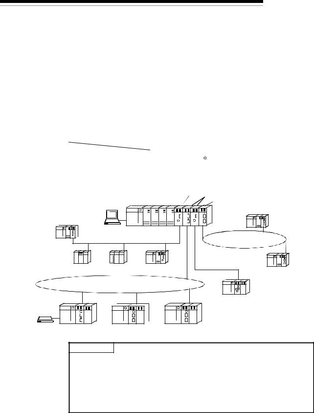
The MELSECNET/H system includes the following 2 types of networks: |
|
|||
1) |
PLC to PLC network for communications between a control station and normal |
|
|
|
|
stations |
|
|
|
2) |
Remote I/O network for communications between a remote master station and |
|
|
|
|
remote I/O stations |
|
|
|
This is the manual to read when building a remote I/O network for MELSECNET/H systems (hereinafter referred to as MELSECNET/H). For building a MELSECNET/H PLC to PLC network, please refer to the Q Corresponding MELSECNET/H Network System Reference Manual. (PLC to PLC network) (SH-080049)
POINT
The Basic model QCPU and safety CPU cannot configure a remote I/O network in a MELSECNET/H network system.
REMARKS
(1)The previous network, called MELSECNET/10H is now called MELSECNET/H.
(2)A network module installed on the remote master station is referred to as a master module.
A network module installed on a remote I/O station is referred to as a remote I/O module.
1 - 1 |
1 - 1 |
1 OVERVIEW
1.1 Overview
MELSEC-Q
1 |
|
The MELSECNET/H remote I/O network system has more functionality and capacity |
||
|
|
than the former network system, MELSECNET/10 network system (hereafter referred |
||
|
|
to as MELSECNET/10). |
|
|
|
|
As the MELSECNET/H remote I/O network adopts the same module mounting method |
||
|
|
as the usual one (mounting I/O modules and intelligent function modules onto the main |
||
|
|
and extension base units), each module mounted on the remote I/O stations can be |
||
|
|
handled in the similar way as the basic one. |
|
|
|
|
In addition, the usability of the MELSECNET/10 remote I/O network has been further |
||
|
|
enhanced so that networks can be easily configured for factory automation systems. |
||
|
|
For the optical loop system in the MELSECNET/H remote I/O network, the |
||
|
|
communication speed can be set to 25 Mbps or 10 Mbps. |
|
|
|
|
|
|
|
|
|
|
Network system |
Communication speed |
|
|
MELSECNET/H |
Optical loop 1 |
25 Mbps |
|
|
Optical loop, coaxial bus |
10 Mbps |
|
|
|
|
||
 1: QJ71LP21-25, QJ71LP21S-25, and QJ72LP25-25 only
Control station (MELSECNET/10 mode) Remote master station
GX Developer |
QCPU |
Control station (MELSECNET/H mode) |
|
|
QCPU normal station |
||
|
|
|
|
QCPU normal station |
|
|
|
MELSECNET/H (10Mbps) |
MELSECNET/H (25Mbps) |
||
|
PLC to PLC network |
||
|
PLC to PLC network |
||
|
|
|
|
|
|
|
MELSECNET/H (10Mbps) |
QnACPU |
AnUCPU |
QCPU |
remote I/O network |
normal station |
normal station |
normal station |
QCPU normal station |
MELSECNET/H (25Mbps) remote I/O network |
||
Remote I/O station |
Remote I/O station |
Remote I/O station |
Remote I/O station |
||
GX Developer 
POINT
(1)Select QCPUs for MELSECNET/H remote I/O networks.
(2)Remote I/O networks and PLC to PLC networks cannot be mixed on the same MELSECNET/H network. Always build separate networks.
(3)Only MELSECNET/H network modules can be connected to a MELSECNET/H remote I/O network. Any MELSECNET/10 network modules (AJ72LP25, A1SJ72QLP25, etc.) are not connectable.
1 - 2 |
1 - 2 |

1 OVERVIEW
MELSEC-Q
The following table shows the types of networks the CPU modules can be connected to.
|
Type of networks |
|
Network to be connected |
|
|
CPU module |
that can be used |
MELSECNET/10 |
MELSECNET/H |
||
|
with CPU |
PLC to PLC network |
Remote I/O network |
PLC to PLC network |
Remote I/O network |
|
MELSECNET/H |
|
|
|
|
QCPU |
(10 Mbps) |
(MELSECNET/10 mode) |
|
(MESLECNET/H mode, |
|
MELSECNET/H |
|
|
MELSECNET/H |
|
|
|
|
|
|
||
|
(25 Mbps) |
|
|
Extended mode) |
|
AnUCPU |
MELSECNET/10 |
|
|
|
|
QnACPU |
MELSECNET/10 |
|
|
|
|
 : Can be used
  : Cannot be used
1.2 Features
The MELSECNET/H remote I/O network has the following features.
(1)Realization of a high-speed communication system
(a)High-speed data communication at 10 Mbps/25 Mbps is possible. (25Mbps is available for only the optical loop type QJ71LP21-25, QJ71LP21S-25 and QJ72LP25-25.)
(2)Large-scale and flexible system configuration
(a)The link device has a larger capacity: 16384 points for the link relay (LB), 16384 points for the link register (LW), and 8192 points for the link inputs (LX)/link outputs (LY). (Refer to Section 2.1.3, "Available device range settings.")
(b)A maximum of 4096 I/O points can be set for each remote I/O station. The link points between a remote master station and a remote I/O station can be set up to 1600 bytes. The link points of up to 2000 bytes can be set
between a master station and a sub-master station on a multiplexed remote I/O network.
(c)Either of the following systems can be chosen: the optical loop system which allows a long station-to-station distance and total distance (up to 30 km (98430 ft.)) and is resistant to noise, or the coaxial bus system (maximum cable distance of 500 m (1640.5 ft.)) which can be wired easily. (Refer to Section 3.1, "Performance Specifications.")
1 - 3 |
1 - 3 |

1 OVERVIEW
MELSEC-Q
(d)The following functions facilitate network connection:
1)Any station to be connected in the future can be specified as a reserved station.
Specifying a station not actually connected as a reserved station prevents a communication error. (Refer to Section 5.1.3 "Common parameter.")
2)It is not necessary to connect stations in order of the station Nos. in the network. (Refer to Section 4.2.1, 4.2.2.)
(e)The parameters can be written to remote I/O modules using GX Developer in the same way as to CPU modules.
The parameters of the remote I/O module can be used to change the detailed settings (response time, error time output mode) for I/O modules on the remote I/O station, intelligent function module switch settings and I/O assignments, and remote password settings.
(Refer to Section 5.2 "Remote I/O Station Parameter Settings".)
(f)Setting up a master station (DMR) and a sub-master station (DSMR) on the multiplexed remote I/O network allows the sub-master station to take over the control of remote I/O stations (R) in case of the master station's failure. (The Process CPU should be used for the multiplexed remote master station and sub-master station.)
By making a parameter setting, the multiplexed remote sub-master station can continue the control of the remote I/O stations even if the master station has recovered to normal and rejoined to the system. (Setting for the recovered master station to control the remote I/O stations is also available.)
(Refer to Section 7.10 "Multiplex Remote Master Function (Process CPU)".)
|
Multiplexed remote |
|
|
|
|
Multiplexed remote |
||||||||||||||||||||||||||||||||||||||||||||||||||
|
master station (DMR) |
|
|
|
|
sub-master station (DSMR) |
||||||||||||||||||||||||||||||||||||||||||||||||||
|
|
|
|
|
|
|
|
|
|
|
|
|
|
|
|
|
|
|
|
|
|
|
|
|
|
|
|
|
|
|
|
|
|
|
|
|
|
|
|
|
|
|
|
|
|
|
|
|
|
|
|
|
|
|
|
|
|
|
|
|
|
|
|
|
|
|
|
|
|
|
|
|
|
|
|
|
|
|
|
|
|
|
|
|
|
|
|
|
|
|
|
|
|
|
|
|
|
|
|
|
|
|
|
|
|
|
|
|
|
|
|
|
|
|
|
|
|
|
|
|
|
|
|
|
|
|
|
|
|
|
|
|
|
|
|
|
|
|
|
|
|
|
|
|
|
|
|
|
|
|
|
|
|
|
|
|
|
|
|
|
|
|
|
|
|
|
|
|
|
|
|
|
|
|
|
|
|
|
|
|
|
|
|
|
|
|
|
|
|
|
|
|
|
|
|
|
|
|
|
|
|
|
|
|
|
|
|
|
|
|
|
|
|
|
|
|
|
|
|
|
|
|
|
|
|
|
|
|
|
|
|
|
|
|
|
|
|
|
|
|
|
|
|
|
|
|
|
|
|
|
|
|
|
|
|
|
|
|
|
|
|
|
|
|
|
|
|
|
|
|
|
|
|
|
|
|
|
|
|
|
|
|
|
|
|
|
|
|
|
|
|
|
|
|
|
|
|
|
|
|
|
|
|
|
|
|
|
|
|
|
|
|
|
|
|
|
|
|
|
|
|
|
|
|
|
|
|
|
|
|
|
|
|
|
|
|
|
|
|
|
|
Remote I/O station (R) Remote I/O station (R) Remote I/O station (R)
1 - 4 |
1 - 4 |
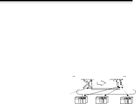
1 OVERVIEW
MELSEC-Q
(g)The redundant system uses the multiplex remote master function to control I/O modules and intelligent function modules. (The Redundant CPU should be used in the redundant system.)
If the multiplexed master station (control system) fails, the multiplex remote master function will switch the master station from "control system" to "standby system". At this time, the multiplexed remote sub-master station is switched from "standby" to "control", continuing the remote I/O control. The sub-master station (control system) that is controlling the remote I/O stations will keep its control even if the master station (standby system) has returned to normal status.
(Refer to Section 7.11 "Multiplex Remote Master Function for Redundant System (Redundant CPU)".)
Multiplexed remote master station (DMR) |
Multiplexed remote sub-master station (DSMR) |
||||||||||||||||||
Control system Standby system |
Standby system Control system |
||||||||||||||||||
|
|
|
|
|
|
|
|
|
|
|
|
|
|
|
|
|
|
|
|
|
|
|
|
|
|
|
|
|
|
|
|
|
|
|
|
|
|
|
|
|
|
|
|
|
|
|
|
|
|
|
|
|
|
|
|
|
|
|
|
|
|
|
|
|
|
|
|
|
|
|
|
|
|
|
|
|
|
|
|
|
|
|
|
|
|
|
|
|
|
|
|
|
|
|
|
|
|
|
|
|
|
|
|
|
|
|
|
|
|
|
|
|
|
|
|
|
|
|
|
|
|
|
|
|
|
|
|
|
|
|
|
|
|
|
|
|
|
|
|
|
|
|
|
|
|
|
|
|
|
|
|
|
|
|
|
|
|
|
|
Tracking cable
Remote I/O station (R) Remote I/O station (R) Remote I/O station (R)
(h)A maximum of 7 extension base units can be connected to the remote I/O module (eight base units including the main base unit), allowing the installation of up to 64 modules.
The maximum overall length of extension cables is 13.2m, ensuring a flexible layout of extension base units.
1 - 5 |
1 - 5 |
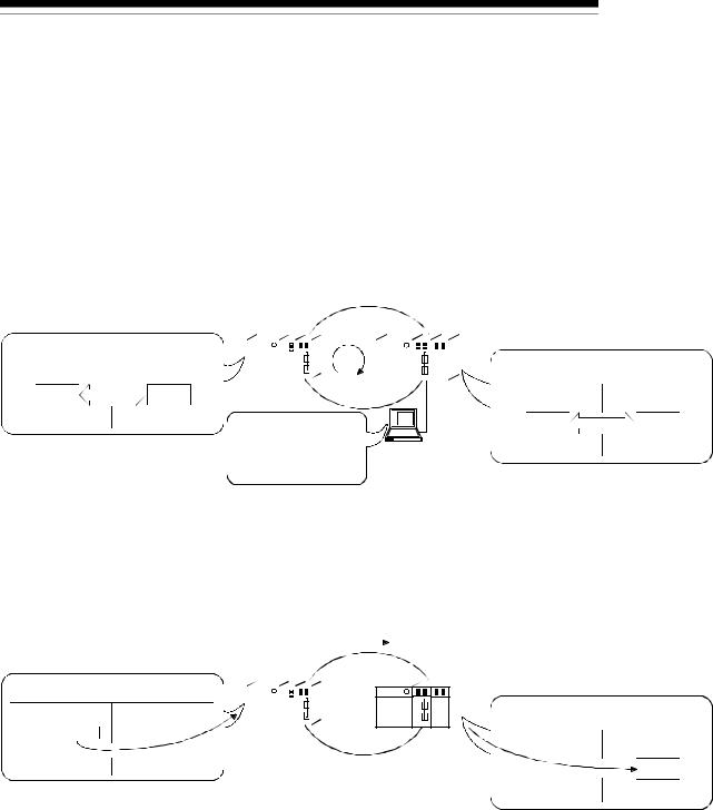
1 OVERVIEW
MELSEC-Q
(3)Providing versatile communication services
(a)Reading data from and writing data to intelligent function modules mounted on remote I/O stations are easy.
There are four methods available for reading and writing.
1)Use GX Configurator to make the initial settings and automatic refresh settings with intelligent function module parameters, and write them
into the remote I/O module in the remote I/O station.
By refreshing the intelligent function module data to the link register W of the remote I/O module based on the auto refresh settings, the remote master station can read/write refreshed data by cyclic transmission.
|
Remote master station |
|
|
|
|
|
|
Remote I/O station |
||||||||||||||
|
|
|
QCPU |
LW |
|
|
|
|
|
Intelligent function module |
||||||||||||
QCPU |
Master module |
|
|
|
|
|
|
|
|
|
|
|
|
|
|
|
|
|
|
|
|
|
|
|
|
|
|
|
|
|
|
|
|
|
|
|
|
|
|
|
|
|
|
||
|
|
|
|
|
|
|
|
|
|
|
|
|
|
|
|
|
|
|
|
|
||
Link register W |
Link register LW |
|
|
|
|
|
|
|
|
|
|
|
|
|
|
|
|
|
|
|
|
|
|
|
|
|
|
|
|
|
|
|
|
|
|
|
|
|
|
|
|
|
|
||
|
|
|
|
|
|
|
|
|
|
|
|
|
|
|
|
|
|
|
|
|
||
|
|
|
|
|
|
|
|
|
|
|
|
|
|
|
|
|
|
|
|
|
||
|
|
|
|
|
|
|
|
|
|
|
|
|
|
|
|
|
|
|
|
|
|
|
Refresh |
|
|
|
|
|
|
|
|
|
Link register W |
||||||||||||
|
|
|
|
|
|
|
|
|
|
|
|
|
|
|
|
|
|
|
|
|
|
|
Refresh
GX
Configurator
2)Link dedicated instructions can be used to directly read from or write to the buffer memory of the intelligent module.
•REMFR instruction: Reads data from the buffer memory of the remote I/O station intelligent function module.
•REMTO instruction: Writes data to the buffer memory of the remote
I/O station intelligent function module.
|
REMTO |
||
Remote master station |
|
|
Remote I/O station |
QCPU |
|
|
Intelligent function module |
QCPU |
Master module |
|
|
|
|
|
|
|
|
|
|
|
|
|
|
|
|
|
|
|
|
|
|
|
|
|
|
|
|
|
|
||
|
|
|
|
|
|
|
|
|
|
|
|
|
|
|
||
|
|
|
|
|
|
|
|
|
|
|
|
|
|
|
|
|
|
|
|
|
|
|
|
|
|
|
|
|
|
|
|
|
|
|
|
|
|
|
|
|
|
|
|
|
|
|
|
|
|
|
|
|
|
|
|
|
|
|
|
|
|
|
|
|
|
|
|

 Z.REMTO
REMTO
1 - 6 |
1 - 6 |

1 OVERVIEW
MELSEC-Q
3)By refreshing the intelligent function module data into the remote I/O module's data register D by the automatic refresh setting of the intelligent function module parameters, the remote master station can read/write data from/to the data register D with READ or WRITE
instruction.
|
WRITE |
|
Remote master station |
|
Remote I/O station |
|
||
QCPU |
|
Intelligent function module |
QCPU |
Master station |
|
|
|
|
|
|
|
|
|
||
|
|
|
|
|
|
|
|
|||||
|
|
|
|
|
|
|
|
|
|
|||
|
|
|
|
|
|
|
|
|
|
|
|
|
|
|
|
|
|
|
|
|
|
|
|
|
|
|
|
|
|
|
|
|
|
|
|
|
|
|

 JP.WRITE
WRITE
Refresh
GX
Configurator
QCPU |
Master station |
Link register W |
Link register LW |
Refresh
4)The automatic refresh setting of the intelligent function parameters enables the intelligent function module data to be refreshed into the remote I/O module's data register D. By refreshing the data register D to the link register W with the parameter of the remote I/O module, the remote master station can read/write the intelligent function module data by cyclic transmission.
This method has the advantage that the intelligent function module parameters created for a QCPU can be applied to the remote I/O module without making any modifications.
Remote master station |
|
|
|
|
|
|
|
|
|
|
Remote I/O station |
|
|
|
||||||||||||||
|
|
|
QCPU |
|
|
|
|
|
|
|
|
|
|
Intelligent function module |
|
|
|
|||||||||||
|
|
|
|
|
|
|
|
|
|
|
LW |
|
|
|
|
|
|
|
|
|
|
|
|
|
Link |
Data |
|
Buffer |
|
|
|
|
|
|
|
|
|
|
|
|
|
|
|
|
|
|
|
|
|
|
|
|
|
||||
|
|
|
|
|
|
|
|
|
|
|
|
|
|
|
|
|
|
|
|
|
|
|
|
|
|
|||
|
|
|
|
|
|
|
|
|
|
|
|
|
|
|
|
|
|
|
|
|
|
|
|
|
|
|||
|
|
|
|
|
|
|
|
|
|
|
|
|
|
|
|
|
|
|
|
|
|
|
|
|
|
|||
|
|
|
|
|
|
|
|
|
|
|
|
|
|
|
|
|
|
|
|
|
|
|
|
|
|
|||
|
|
|
|
|
|
|
|
|
|
|
|
|
|
|
|
|
|
|
|
|
|
|
|
|
|
|||
|
|
|
|
|
|
|
|
|
|
|
|
|
|
|
|
|
|
|
|
|
|
|
|
|
|
|||
|
|
|
|
|
|
|
|
|
|
|
|
|
|
|
|
|
|
|
|
|
|
|
|
|
|
|||
|
|
|
|
|
|
|
|
|
|
|
|
|
|
|
|
|
|
|
|
|
|
|
|
|
|
|||
|
|
|
|
|
|
|
|
|
|
|
|
|
|
|
|
|
|
|
|
|
|
|
|
|
register W |
register D |
|
memory |
|
|
|
|
|
|
|
|
|
|
|
|
|
|
|
|
|
|
|
|
|
|
|
|
|
Refresh |
|
Refresh |
|
|
|
|
|
|
|
|
|
|
|
|
|
|
|
|
|
|
|
|
|
|
||||||||
|
|
|
|
|
|
|
|
|
|
|
|
|
|
|
GX |
|
|
|
||||||||||
|
|
|
|
|
|
|
|
|
|
|
|
Configurator |
|
|
|
|||||||||||||
(b)The interrupt sequence program of the host's CPU module can be started up using the event issue function. This function reduces the response time of the system and enables real-time data reception.
(Refer to Section 7.7 "Interrupt Settings".)
|
|
CPU module |
|
|
|
|
Network module |
MELSECNET/H |
|
|
MAIN |
|
|
|
|
Condition check |
|
|
|
Conditions |
|
|
|
|||
|
|
Normal |
Interrupt condition |
|
||||
I50 |
|
sequence |
matched |
|
||||
Interrupt |
program |
|
|
|
parameters |
Cyclic transmission |
||
|
|
|
||||||
|
|
|
|
• |
Relay information |
|||
|
sequence |
|
|
|
|
|
||
|
program |
|
|
|
|
• |
Register data |
|
|
IRET |
|
|
|
• |
Network status |
|
|
|
|
END |
|
|
|
|
|
|
|
|
|
|
|
|
|
|
|
1 - 7 1 - 7

1 OVERVIEW
MELSEC-Q
(4)Enhanced RAS functions (Refer to Section 3.2.2 "RAS functions")
(a)When a faulty station recovers and can resume normal operation, it automatically returns to the network to resume the data communication using the automatic return function.
(b)By using the loopback function (in the optical loop system), it is possible to continue data transmission among operational stations by disconnecting faulty areas such as a part of the network where there is a cable disconnection, a faulty station, etc.
(c)By using the station detach function (in the coaxial bus system), even when some of the connected stations are down due to power off, etc., the normal communication can be continued among other operational stations.
(d)The network module can continue the transient transmission even if an error, which stops the CPU module, occurs during system operation.
(e)The time of transient error occurrence can be checked.
(f)By mounting 2 power supply modules on a remote I/O station, either of them can be replaced without powering off the station. (Redundant power supply on remote I/O station)
The redundant power supply base unit is required for mounting 2 power supply modules.
(g)When an input module, an output module or an intelligent function module mounted on a remote I/O station fails, the faulty module can be replaced without stopping the system operation. (Online module change)
Online module change is executable for the Q series I/O modules and modules of function version C and later, such as analog-to-digital converter modules, digital-to-analog converter modules, channel isolated thermocouple input modules, and temperature control modules.
REMARKS
The following faults make the RAS functions valid.
•Break in cable
•Power-off of slave station
•Network setting error
•Fault detectable by self-diagnostics of CPU module
If the network module has become faulty, the RAS functions may not be activated depending on the fault.
(5)Control of external connection to remote I/O stations (refer to
Section 7.12)
Setting a remote password for a remote I/O station restricts access from the outside via an Ethernet interface module or serial communication module. (Remote password)
1 - 8 |
1 - 8 |
Loading...