


|
|
|
|
|
|
|
|
2007 |
|
|
|
|
|
|
|
|
|
||
|
|
|
|
|
|
|
|
||
SPLIT-TYPE, AIR CONDITIONERS |
|||||||||
|
|||||||||
TECHNICAL & SERVICE MANUAL
Series PE Ceiling Concealed
Indoor unit
[Model names]
PE-8GAK(T)
PE-10GAK(T)
PE-12GAK(T)
PE-16GAK(T)
PE-20GAK(T)
CONTENTS
1.TYPES OF CONNECTED OUTDOOR UNITS ·····2
2.SAFETY FOR USE ··································3
3.PART NAMES AND FUNCTIONS ···········7
4.SPECIFICATIONS ···································9
5.DATA ······················································13
6.OUTLINES AND DIMENSIONS·············21
7.WIRING DIAGRAM································25
Indoor unit
8.REFRIGERANT SYSTEM DIAGRAM ···27
9.TROUBLESHOOTING···························28 10.FUNCTION SETTING ····························41
11.SYSTEM CONTROL······························45
12.SERVICE DATE PART NANES·············53
Remote controller
13.OPTIONAL PARTS································57
NOTE:
•This service manual describes technical data of indoor units.
•RoHS compliant products have <G> mark on the spec name plate.

1 
 TYPES OF CONNECTED OUTDOOR UNITS
Types of connected outdoor units
Indoor unit |
|
Outdoor unit |
|
Model name |
|
Service manual No. |
|
|
|
||
|
|
|
|
PE - 8GAK(T) |
PU - 8YAKD |
|
HWE07070 |
PE - 10GAK(T) |
PU - 10YAKD |
|
HWE07070 |
PE - 12GAK(T) |
PU - 12YAKD |
|
HWE07070 |
PE - 16GAK(T) |
PU - 8YAKD X 2 |
|
HWE07070 |
PE - 20GAK(T) |
PU - 10YAKD X 2 |
|
HWE07070 |
Outdoor Unit List
Specification |
|
|
|
|
High static pressure motor |
|
Standard Model |
High static pressure motor |
Steel fan |
|
|
|
|
/steel fan |
|||
Model name |
|
|
|
|
|
|
|
|
|
|
|
PE - 8GAK |
PE-8GAK.TH |
PE-8GAK.TH-SP |
PE-8GAK.TH-MF |
|
PE-8GAK.TH-SPMF |
|
|
|
|
|
|
PE - 10GAK |
PE-10GAK.TH |
PE-10GAK.TH-SP |
PE-10GAK.TH-MF |
|
PE-10GAK.TH-SPMF |
|
|
|
|
|
|
PE - 12GAK |
PE-12GAK.TH |
- |
PE-12GAK.TH-MF |
|
- |
|
|
|
|
|
|
PE - 16GAK |
PE-16GAK.TH |
- |
- |
|
- |
|
|
|
|
|
|
PE - 20GAK |
PE-20GAK.TH |
- |
- |
|
- |
|
|
|
|
|
|
|
|
|
|
|
|
Specification |
|
|
|
|
|
Model name |
Standard Model |
High static pressure motor |
|||
|
|
|
|
|
|
PE - 8GAKT |
PE-8GAKT.TH |
PE-8GAKT.TH-SP |
|||
|
|
|
|||
PE - 10GAKT |
PE-10GAKT.TH |
PE-10GAKT.TH-SP |
|||
|
|
|
|
|
|
PE - 12GAKT |
PE-12GAKT.TH |
|
- |
|
|
|
|
|
|
|
|
PE - 16GAKT |
PE-16GAKT.TH |
|
- |
|
|
|
|
|
|
|
|
PE - 20GAKT |
PE-20GAKT.TH |
|
- |
|
|
|
|
|
|
|
|
2
2 
 SAFETY FOR USE
2.1 SAFETY FOR USE
Before conducting installation work, please read this ''SAFETY FOR USE'' carefully for correct installation.
Since the caution items shown here contain important description relative to safety, please observe them without fail.
Warning |
Erroneous handling gives a high possibility to induce serious results such as |
|
death or heavy injury. |
 Caution Erroneous handling may induce serious injury depending on the situation.
After reading, please keep it with you together the Instruction Manual, and read it again at the movement of the unit.
 Warning
The unit should not be installed by the user.
If the unit is installed improperly, explosion, water leakage, electric shock or fire may be result. Consult your dealer or specialist subcontractor for repair and movement.
For installation, conduct the work correctly by following the Installation Manual.
Improper installation may cause a fire, electrical shock or water leakage.
Install the unit on a spot sufficiently durable against the unit weight.
Insufficient durability can cause an injury by the falling down of unit.
All electric work must be performed by licensed technician, according to local regulations and the instructions given in this manual.
The units should be powered by dedicated power lines. Power lines with insufficient capacity or improper electrical work may result in electric shock or fire.
Use only the specified cables for wiring. The connections must be made secured without tension the terminals.
Improper connection or fastening can cause a fire or electrical shock.
The unit should be installed according to the instructions in order to minimize the risk of damage from earthquakes, typhoons or strong winds.
Improper installation work can cause an injury by the falling down of the unit.
The outdoor unit must be installed on stable, level surface, in a place where there is no accumulation of snow , leaves or rubbish.
The outdoor unit should be installed in a location where air and noise emitted by the unit will not disturb the neighbors. The indoor unit should be securely installed.
If the unit is loosely mounted, it may fall, and cause injury.
When installing or relocating the unit, make sure that no substance other than the specified refrigerant enters the refrigerant circuit.
Any presence of foreign substance such as air can cause abnormal pressure rise or explosion.
3
Never repair the unit, remodel or transfer it to another site by yourself.
If they are performed improperly, water leakage, electric shock or fire may result. If you need to have the unit repaired or moved, consult your dealer.
Use only the specified refrigerant (R-22) to charge the refrigerant circuit.
Do not mix it with any other refrigerant and do not allow air to remain in the circuit.
Air enclosed in the circuit can cause high pressure resulting in a rupture and other hazards.
Ventilate the room if refrigerant leaks during Installation.
The refrigerant heated generates poisonous gas by decomposition which can cause poisoning.
After completing installation work, make sure that refrigerant gas has not leaked.
If refrigerant gas has leaked and exposed to fan heater, stove, oven and so on, it may generate noxious gases.
Take a proper measure to suppress the critical concentration of refrigerant if leaked when installing the unit in a small room.
The limit density is made not to be exceeded even if the refrigerant leaks by any chance.
You are necessary to ventilation measures to prevent the accident. If the refrigerant leaks, hypoxia accident may caused.
For the countermeasure to be taken, consult your dealer.
The terminal block cover of unit must be firmly attached to prevent entry of dust and moisture.
Improper mounting of the cover cause electric shock or fire.
Use only optional parts authorised by Mitsubishi Electric.
If the accessories are installed improperly, water leakage, electric shock or fire may result.
Ask your dealer or an authorised company to install them.

 Caution
Never install on the place where a combustible gas might leak.
The gas may ignite or explode when the gas leaks and collects in surrounding of the unit.
When the unit is installed at telecommunication centers or hospitals, take a proper provision against noise.
The erroneous operation of air conditioner may be induced by inverter equipment, independent power device, medical equipment or communication equipment.
While the erroneous operation of medical equipment or communication equipment may caused by the air conditioner.
For special use as for foods, animals/plants, precision equipment or art objects, the applicability should be confirmed beforehand.
As the use for the applications other than that designed originally may result in the deterioration of the quality. Consult your dealer in this regard.
Do not use the unit under a special atmosphere.
Installing the unit at the following places may cause a trouble, a place where much machine oil, salt sonnet, humidity or dust, spa district, a place full of sulfur gas, volatile gas, or corrosive gas, a place near high frequency processing machine.
Thermal insulation of the drain pipes is necessary prevent dew condensation.
If the drain pipes are not properly insulated, condensation will result and drip on ceiling, floor or other possessions.
The drain piping must process by surely,and insulate the drain piping not to be dewy.
When the room humidity exceeds 80% or when the drain pipe is clogged, water may drip from the indoor unit. The outdoor unit produces condensation during the heating operation.
Make sure to provide drainage around the outdoor unit if such condensation is likely to cause damage.
Install drain piping according to this Installation Manual to ensure proper drainage.
Place thermal insulation on the pipes to prevent condensation.
Improper drain piping may cause water leakage and damage to furniture or other possessions.
The unit must be properly earth connected.
Do not connect the earth wire to gas pipe, city water pipe, lightning rod or telephone earth wire.
Improper earth connection may cause electrical shock.
When installing at a watery place, provide an electric leak breaker.
Failure to mount the electric leak breaker may cause electrical shock.
Use breaker or fuse with proper capacity. Make sure that there is a main power switch.
Using a wire or a copper wire instead of proper capacity of fuse can cause fire or trouble.
Other appliances connected to the same line could cause an overload.
For the power lines, use standard cables of sufficient current capacity.
Otherwise, current leakage, overheating or fire may occur.
When installing the power lines, do not apply tension to the cables.
The tighten or loosen the connections may cause generate heat and cause fire.
Remote controller is not pushed with the thing sharpening ahead.
It occasionally causes the electric shock and the breakdown.
Arrange the configuration of wiring not to bring up the panel and terminal cover, and fasten the panel and terminal cover securely.
The poor mounting of the panel or terminal cover may cause the heat generation of the terminal connection, a fire or electrical shock.
Do not wash the unit with water.
If washed with water, electrical shock may be caused.
Do not handle the switch with wet hands.
Otherwise electrical shock can be resulted.
Be very careful on handling the unit.
When carrying in outdoor unit, be sure to support it at four points.
Carrying in and lifting with 3-point support may make outdoor unit unstable, resulting in a fall of it.
The unit should not be carried by only one person if it is more than 20kg.
Some units use PP bands for packing.
Do not use any PP band for delivery purpose.
Do not touch the heat exchanger fins with your bear hands.
Doing so may cut your hands.
Be sure to safely dispose the packaging materials. Packaging materials, such as catches and other metal or wooden parts, may cause stabs or other injuries. Tear off and discard plastic packing bags so that children will not play any of them.
If children play with a plastic bag which was not torn off, it may cause a risk of suffocation.
Do not leave the mounting base being damaged.
The damaged base may cause the falling down of the unit which may give injury.
Turn on the main power switch more than 6 hours before starting operation.
Do not turn the main power switch OFF during seasons of heavy use, doing so can result in failure.
Do not touch the compressor or refrigerant piping without wearing glove on your hands.
Touching directly such part can cause a burn or frostbite as it becomes high or low temperature according to the refrigerant state.
Do not touch the metal edges inside the unit without wearing glove on your hands.
Touching directly it may injure your hands.
Do not remove the panel or the fan guard from the outdoor unit when it is running.
You could be injured if you touch rotating, hot or highvoltage parts.
Do not operate the air conditioner without the air filter set place.
Dust may accumulate, and cause a failure.
At emergency (if you smell something burning), stop operation and turn the power source switch off.
Continuing the operation without eliminating the emergency state may cause a machine trouble, fire, or electrical shock.
After stopping operation, be sure to wait for five minutes before turning off the main power switch.
Otherwise, water leakage or unit failure may occur.
Remote controller is not installed for the place where direct sunshine strikes.
Do not connect the unit in the reverse phase sequence.
If connected in the reverse phase sequence, the indoor unit will not be able to provide sufficient cooling air.
The fan on the outdoor unit that is connected in the reverse phase sequence will turn in the wrong direction and makes the compressor rattle, and it will result in compressor damage.
4

2-2 SAFETY PRECAUTIONS
2-2-1 Before installation and electric work
sBefore installing the unit, make sure you read all the “Safety precautions”.
sThe “Safety precautions” provide very important points regarding safety. Make sure you follow them.
Symbols used in the text
 Warning:
Describes precautions that should be observed to prevent danger of injury or death to the user.
 Caution:
Describes precautions that should be observed to prevent damage to the unit.
Symbols used in the illustrations
: Indicates an action that must be avoided.
: Indicates that important instructions must be followed. : Indicates a part which must be grounded.
: Beware of electric shock. <Color: yellow>
 Warning:
Carefully read the labels affixed to the unit.
 Warning:
•Ask the dealer or an authorized technician to install the air conditioner.
-Improper installation by the user may result in water leakage, electric shock, or fire.
•Install the unit at a place that can withstand its weight.
-Inadequate strength may cause the unit to fall down, resulting in injuries.
•Use the specified cables for wiring. Make the connections securely so that the outside force of the cable is not applied to the terminals.
-Inadequate connection and fastening may generate heat and cause a fire.
•Prepare for strong winds and earthquakes and install the unit at the specified place.
-Improper installation may cause the unit to topple and result in injury.
•Always use an filter and other accessories specified by Mitsubishi Electric.
-Ask an authorized technician to install the accessories. Improper installation by the user may result in water leakage, electric shock, or fire.
•Never repair the unit. If the air conditioner must be repaired, consult the dealer.
-If the unit is repaired improperly, water leakage, electric shock, or fire may result.
•Do not touch the heat exchanger fins and metal edges.
-Improper handling may result in injury.
•If refrigerant gas leaks during installation work, ventilate the room.
-If the refrigerant gas comes into contact with a flame, poisonous gases will be released.
•Install the air conditioner according to this Installation Manual.
-If the unit is installed improperly, water leakage, electric shock, or fire may result.
•Have all electric work done by a licensed electrician according to “Electric Facility Engineering Standard” and “Interior Wire Regulations”and the instructions given in this manual and always use a special circuit.
-If the power source capacity is inadequate or electric work is performed improperly, electric shock and fire may result.
•Securely install the terminal cover (panel).
-If the terminal cover (panel) is not installed properly, dust or water may enter the outdoor unit and fire or electric shock may result.
•When installing and moving the air conditioner to another site, do not charge the it with a refrigerant different from the refrigerant (R22) specified on the unit.
-If a different refrigerant or air is mixed with the original refrigerant, the refrigerant cycle may malfunction and the unit may be damaged.
•If the air conditioner is installed in a small room, measures must be taken to prevent the refrigerant concentration from exceeding the safety limit even if the refrigerant should leak.
-Consult the dealer regarding the appropriate measures to prevent the safety limit from being exceeded. Should the refrigerant leak and cause the safety limit to be exceeded, hazards due to lack of oxygen in the room could result.
•When moving and reinstalling the air conditioner, consult the dealer or an authorized technician.
-If the air conditioner is installed improperly, water leakage, electric shock, or fire may result.
•After completing installation work, make sure that refrigerant gas is not leaking.
-If the refrigerant gas leaks and is exposed to a fan heater, stove, oven, or other heat source, it may generate noxious gases.
•Do not reconstruct or change the settings of the protection devices.
-If the pressure switch, thermal switch, or other protection device is shorted and operated forcibly, or parts other than those specified by Mitsubishi Electric are used, fire or explosion may result.
•To dispose of this product, consult your dealer.
•The installer and system specialist shall secure safety against leakage according to local regulation or standards.
-Following standards may be applicable if local regulation are not available.
•Pay a special attention to the place, such as a basement, etc. where refrigeration gas can stay, since refrigeration is heavier than the air.
•The appliance is not intended for use by young children or infirm persons without supervision.
•Young children should be supervised to ensure that they do not play with the appliance.
•Never operate in open phase condition. Control box may be broken.
2-2-2 Before Installation
 Caution:
•Do not install the unit where combustible gas may leak.
-If the gas leaks and accumulates around the unit, an explosion may result.
•Do not use the air conditioner where food, pets, plants, precision instruments, or artwork are kept.
-The quality of the food, etc. may deteriorate.
•Do not use the air conditioner in special environments.
-Oil, steam, sulfuric smoke, etc. can significantly reduce the performance of the air conditioner or damage its parts.
•When installing the unit in a hospital, communication station, or similar place, provide sufficient protection against noise.
-The inverter equipment, private power generator, high-frequency medical equipment, or radio communication equipment may cause the air conditioner to operate erroneously, or fail to operate. On the other hand, the air conditioner may affect such equipment by creating noise that disturbs medical treatment or image broadcasting.
•Do not install the unit on a structure that may cause leakage.
-When the room humidity exceeds 80 % or when the drain pipe is clogged, condensation may drip from the indoor unit. Perform collective drainage work together with the outdoor unit, as required.
2-2-3 Before Installation (moved) - electrical work
 Caution:
•Ground the unit.
-Do not connect the ground wire to gas or water pipes, lightning rods, or telephone ground lines. Improper grounding may result in electric shock.
•The reverse phase of L lines (L1, L2, L3) can be detected (Error cord: 4103), but the reverse phase of L lines and N line can be not be detected.
-Some electric parts should be damaged when power is supplied under the miss wiring.
•Install the power cable so that tension is not applied to the cable.
-Tension may cause the cable to break and generate heat and cause a fire.
•Install an leak circuit breaker, as required.
-If an leak circuit breaker is not installed, electric shock may result.
•Use power line cables of sufficient current carrying capacity and rating.
-Cables that are too small may leak, generate heat, and cause a fire.
•Use only a circuit breaker and fuse of the specified capacity.
-A fuse or circuit breaker of a larger capacity or a steel or copper wire may result in a general unit failure or fire.
•Do not wash the air conditioner units.
-Washing them may cause an electric shock.
•Be careful that the installation base is not damaged by long use.
-If the damage is left uncorrected, the unit may fall and cause personal injury or property damage.
•Install the drain piping according to this Installation Manual to ensure proper drainage. Wrap thermal insulation around the pipes to prevent condensation.
-Improper drain piping may cause water leakage and damage to furniture and other possessions.
5

•Be very careful about product transportation.
-Only one person should not carry the product if it weighs more than 20 kg.
-Some products use PP bands for packaging. Do not use any PP bands for a means of transportation. It is dangerous.
-Do not touch the heat exchanger fins. Doing so may cut your fingers.
-When transporting the outdoor unit, suspend it at the specified positions on the unit base. Also support the outdoor unit at four points so that it cannot slip sideways.
•Safely dispose of the packing materials.
-Packing materials, such as nails and other metal or wooden parts, may cause stabs or other injuries.
-Tear apart and throw away plastic packaging bags so that children will not play with them. If children play with a plastic bag which was not torn apart, they face the risk of suffocation.
•Remote controller is not allowed to install for the place where direct sunshine strikes.
2-2-4 Before starting the test run
 Caution:
•Turn on the power at least 12 hours before starting operation.
-Starting operation immediately after turning on the main power switch can result in severe damage to internal parts. Keep the power switch turned on during the operational season.
•Do not touch the switches with wet fingers.
-Touching a switch with wet fingers can cause electric shock.
•Do not touch the refrigerant pipes during and immediately after operation.
-During and immediately after operation, the refrigerant pipes are may be hot and may be cold, depending on the condition of the refrigerant flowing through the refrigerant piping, compressor, and other refrigerant cycle parts. Your hands may suffer burns or frostbite if you touch the refrigerant pipes.
•Do not operate the air conditioner with the panels and guards removed.
-Rotating, hot, or high-voltage parts can cause injuries.
•Do not turn off the power immediately after stopping operation.
-Always wait at least five minutes before turning off the power. Otherwise, water leakage and trouble may occur.
•Do not operate the air conditioner without the air filter set place.
-Dust may accumulate, and cause a failure.
•At emergency (if you smell something burning), stop operation and turn the power source switch off.
-Continuing the operation without eliminating the emergency state may cause a machine trouble, fire, or electric shock.
•Remote controller should be pushed with finger.
-It occasionally causes the electric shock and the breakdown.
6
3 
 PART NAMES AND FUNCTIONS
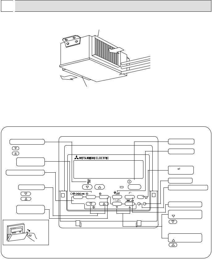
● Indoor (Main) Unit
Air intake duct flange
Air intake
(sucks the air inside the room into the unit)
Air outlet
Air outlet duct flange
● Remote controller
Once the controls are set, the same operation mode can be repeated by simply pressing the ON/OFF button.
● Operation buttons
Set Temperature buttons |
|
|
|
Down |
|
|
|
Up |
|
|
|
Timer Menu button |
|
|
|
(Monitor/Set button) |
|
|
|
Mode button (Return button) |
|
|
|
|
|
TEMP. |
|
Set Time buttons |
|
|
|
Back |
|
MENU |
ON/OFF |
Ahead |
BACK |
MONITOR/SET |
DAY |
|
|||
Timer On/Off button |
PAR-21MAA |
CLOCK |
|
(Set Day button) |
|
|
|
Opening the |
|
|
|
door. |
|
|
|
|
|
ON/OFF button |
||
|
|
Fan Speed button |
||
|
|
Filter |
button |
|
|
|
(<Enter> button) |
||
|
ON/OFF |
Test Run button |
||
|
|
|
|
|
|
|
Check button (Clear button) |
||
|
FILTER |
|
|
|
|
CHECK |
TEST |
|
|
OPERATION |
|
Airflow Up/Down button |
||
CLEAR |
|
|
|
|
|
|
Louver button |
||
|
|
( |
|
Operation button) |
|
|
|
|
To preceding operation |
|
|
|
|
number. |
|
|
Ventilation button |
||
|
|
( |
Operation button) |
|
|
|
|
|
To next operation number. |
7
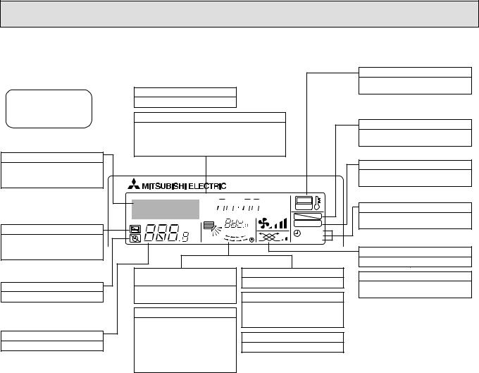
● Display
For purposes of this explanation, all parts of the display are shown as lit. During actual operation, only the relevant items will be lit.
Identifies the current operation
Shows the operating mode, etc.
*Multilanguage display is supported.
“Centrally Controlled” indicator
Indicates that operation of the remote controller has been prohibited by a master controller.
“Timer Is Off” indicator
Indicates that the timer is off.
Temperature Setting
Shows the target temperature.
Day-of-Week
Shows the current day of the week.
Time/Timer Display
Shows the current time, unless the simple or Auto Off timer is set.
If the simple or Auto Off timer is set, shows the time remaining.
TIME SUN MON TUE WED THU FRI SAT
TIMER 


 Hr ON
Hr ON
AFTER 


 AFTER OFF
ERROR CODE |
FUNCTION |
|
˚F˚C |
FILTER |
|
˚F˚C |
||
WEEKLY |
||
ONLY1Hr. |
SIMPLE |
|
AUTO OFF |
Up/Down Air Direction indicator
The indicator  shows the direction of the outcoming airflow.
“One Hour Only” indicator
Displayed if the airflow is set to weak and downward during COOL or DRY mode. (Operation varies according to model.)
The indicator goes off after one hour, at which time the airflow direction also changes.
Room Temperature display
Shows the room temperature.
Louver display
Indicates the action of the swing louver. Does not appear if the louver is stationary.
 (Power On indicator)
Indicates that the power is on.
“Sensor” indication
Displayed when the remote controller sensor is used.
“Locked” indicator
Indicates that remote controller buttons have been locked.
“Clean The Filter” indicator
Comes on when it is time to clean the filter.
Timer indicators
The indicator comes on if the corresponding timer is set.
Fan Speed indicator
Shows the selected fan speed.
Ventilation indicator
Appears when the unit is running in Ventilation mode.
Caution
●Only the Power on indicator lights when the unit is stopped and power supplied to the unit.
●If you press a button for a feature that is not installed at the indoor unit, the remote controller will display the “Not Available” message.
If you are using the remote controller to drive multiple indoor units, this message will appear only if he feature is not present at the parent unit.
●When power is turned ON for the first time, it is normal that “PLEASE WAIT” is displayed on the room temperature indication (For max. 2minutes). Please wait until this “PLEASE WAIT” indication disappear then start the operation.
8
4 |
SPECIFICATIONS |
|
|
|
|
|||
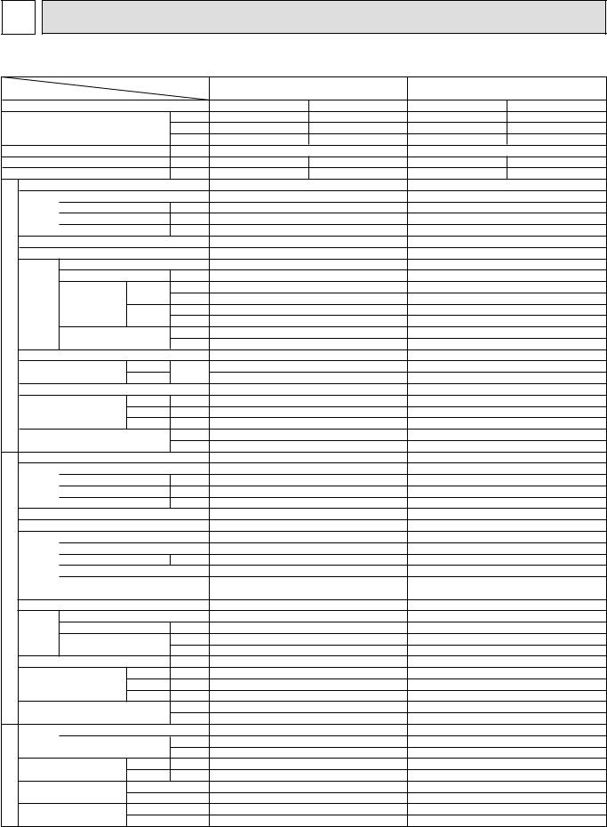
4-1 STANDARD SPECIFICATIONS |
|
|
|
|
||||
Item |
|
Model name |
PE-8GAK(T) |
|
PE-10GAK(T) |
|
||
|
|
|
|
|
||||
|
|
|
|
|
|
|
||
|
|
|
|
|
Gross |
Net |
Gross |
Net |
|
|
|
|
Btu/h |
80,000 |
76,000 |
100,000 |
96,000 |
Capacity 1 |
|
|
kW |
23.4 |
22.4 |
29.3 |
28.2 |
|
|
|
|
|
kcal/h |
20,100 |
19,200 |
25,100 |
24,200 |
Total input |
|
|
kW |
7.43 |
|
10.10 |
2.39 |
|
EER |
|
|
kcal/h.W |
2.7 |
2.58 |
2.48 |
||
COP |
|
|
W/W |
3.14 |
3.01 |
2.9 |
2.79 |
|
|
Model name |
|
|
PE-8GAK(T) |
|
PE-10GAK(T) |
|
|
|
Power supply(phase,cycle,voltage) |
|
3PH 4W 50Hz 380-415V |
3PH 4W 50Hz 380-415V |
||||
|
|
Input |
|
kW |
1.00 |
|
1.10 |
|
|
|
Running current |
|
A |
1.8 |
|
1.9 |
|
|
|
Starting current |
|
A |
5.0 |
|
5.0 |
|
|
External finish |
|
|
Galvanized steel |
|
Galvanized steel |
|
|
|
Heat exchanger |
|
|
Cross fin coil |
|
Cross fin coil |
|
|
|
|
Fan(drive) X No. |
|
Centrifugal (direct) X 2 |
Centrifugal (direct) X 2 |
|||
|
|
Fan motor output |
kW |
0.75 |
|
0.75 |
|
|
UNIT |
|
|
Hi |
CMM |
65 |
|
80 |
|
Fan |
Airflow |
L/s |
1,083 |
|
1,333 |
|
||
|
|
|
||||||
INDOOR |
|
|
Lo |
CMM |
52 |
|
64 |
|
|
|
L/s |
867 |
|
1,067 |
|
||
|
|
|
|
|
||||
|
External static |
|
Pa |
100 |
|
100 |
|
|
|
pressure |
|
mmAq |
10 |
|
10 |
|
|
|
Operation control & Thermostat |
|
Remote control & built in |
Remote control & built in |
||||
|
Noise level 2 |
Hi |
dB(A) |
49 |
|
50 |
|
|
|
Lo |
45 |
|
46 |
|
|||
|
|
|
|
|
|
|||
|
Cond. Drain connection O.D. |
|
R1 |
|
R1 |
|
||
|
|
|
H |
mm |
400 |
|
400 |
|
|
Dimensions |
W |
mm |
1400 |
|
1600 |
|
|
|
|
|
D |
mm |
634 |
|
634 |
|
|
Weight |
|
|
kg |
70 |
|
77 |
|
|
|
|
lbs |
154 |
|
169 |
|
|
|
Model name |
|
|
|
||||
|
|
|
PU-8YAKD |
|
PU-10YAKD |
|
||
|
Power supply(phase,cycle,voltage) |
|
3PH 4W 50Hz 380-415V |
3PH 4W 50Hz 380-415V |
||||
|
|
Input |
|
kW |
6.43 |
|
9.00 |
|
|
|
Running current |
|
A |
12.4 |
|
16.0 |
|
|
|
Starting current |
|
A |
95 |
|
125 |
|
|
External finish |
|
|
Munsell 3Y 7.8/1.1 |
Munsell 3Y 7.8/1.1 |
|||
|
Refrigerant control |
|
|
Capillary tube |
|
Capillary tube |
|
|
UNIT |
Compressor |
|
|
Hermetic |
|
Hermetic |
|
|
|
Model |
|
|
ZR94KC-TFD |
|
ZR125KC-TFD |
|
|
|
Motor output |
|
kW |
5.6 |
|
7.5 |
|
|
OUTDOOR |
|
Starter type |
|
|
Line start |
|
Line start |
|
|
Protection devices |
|
Thermal relay, Thermal switch |
Thermal relay, Thermal switch |
||||
|
|
HP switch, LP switch |
HP switch, LP switch |
|||||
|
|
|
|
|||||
Heat exchanger |
|
|
Cross fin coil |
|
Cross fin coil |
|
||
|
Fan(drive) X No. |
|
Propeller(direct) X 2 |
Propeller(direct) X 2 |
||||
|
|
|
||||||
|
Fan |
Fan motor output |
kW |
0.15 X 2 |
|
0.15 X 2 |
|
|
|
|
|
m3/min |
160 |
|
160 |
|
|
|
|
Airflow |
|
|
|
|||
|
|
|
L/s |
2,667 |
|
2,667 |
|
|
|
Noise level 2 |
|
|
|
||||
|
|
dB(A) |
66 |
|
66 |
|
||
|
Dimensions |
H |
mm |
1480 |
|
1480 |
|
|
|
W |
mm |
1047 |
|
1047 |
|
||
|
|
|
D |
mm |
547 |
|
547 |
|
|
Weigh |
|
|
kg |
197 |
|
206 |
|
|
|
|
lbs |
433 |
|
453 |
|
|
|
|
|
|
|
|
|||
PIPING |
Refrigerant |
|
|
R-22 |
|
R-22 |
|
|
|
Charge |
|
kg |
6.0 |
|
6.5 |
|
|
|
|
lbs |
13.2 |
|
14.3 |
|
||
|
|
|
|
|
||||
|
|
Liquid |
mm |
15.88 |
|
15.88 |
|
|
REFRIGERANT |
Pipe size O.D. |
|
|
|||||
Gas |
mm |
25.4 |
|
28.6 |
|
|||
|
|
|
|
|||||
Connection method |
Indoor side |
Blazed |
|
Blazed |
|
|||
Outdoor side |
Flared/Flanged |
|
Flared/Flanged |
|
||||
|
|
|
|
|||||
Between the indoor & |
Height difference |
Max. 30m |
|
Max. 30m |
|
|||
|
outdoor unit |
Piping length |
Max. 50m |
|
Max. 50m |
|
||
NOTE : 1 |
Rating condition |
|
Cooling : Indoor unit D.B.27°C, W.B.19°C |
|
Outdoor unit D.B.35°C |
|
Refrigerant piping length (one way) : 7.5m (in case of others) |
NOTE : 2 |
Noise level is measured in an unacoustic room based on JIS conditions. |
NOTE : 3 |
Guaranteed operating range is ; Outdoor D.B.20-52°C Indoor W.B.15-24°C |
9
, PE-10GAK(T), PE-12GAK(T), PE-16GAK(T), PE-20GAK(T) Service Manual")
Item |
|
Model name |
PE-12GAK(T) |
PE-16GAK(T) |
PE-20GAK(T) |
||||||
|
|
|
|||||||||
|
|
|
|
|
|
|
|
|
|||
|
|
|
|
|
Gross |
Net |
Gross |
Net |
Gross |
Net |
|
|
|
|
|
Btu/h |
114,500 |
110,000 |
160,000 |
154,000 |
200,000 |
190,000 |
|
Capacity |
1 |
|
kW |
33.5 |
32.3 |
46.8 |
45.3 |
58.6 |
55.8 |
||
|
|
|
|
kcal/h |
28,800 |
27,700 |
40,200 |
38,900 |
50,300 |
47,900 |
|
Total input |
|
kW |
|
11.49 |
14.41 |
|
20.84 |
|
|||
EER |
|
|
kcal/h.W |
2.50 |
2.41 |
2.78 |
2.69 |
2.41 |
2.29 |
||
COP |
|
|
W/W |
2.91 |
2.81 |
3.24 |
3.14 |
2.81 |
2.67 |
||
|
Model name |
|
|
PE-12GAK(T) |
PE-16GAK(T) |
PE-20GAK(T) |
|||||
|
Power supply(phase,cycle,voltage) |
|
3PH 4W 50Hz 380-415V |
3PH 4W 50Hz 380-415V |
3PH 4W 50Hz 380-415V |
||||||
|
|
Input |
|
kW |
|
1.17 |
1.55 |
|
2.84 |
|
|
|
|
Running current |
|
A |
|
2.2 |
3.8 |
|
5.4 |
|
|
|
|
Starting current |
|
A |
|
6.4 |
8.5 |
|
10 |
|
|
|
External finish |
|
|
Galvanized steel |
Galvanized steel |
Galvanized steel |
|||||
|
Heat exchanger |
|
|
Cross fin coil |
Cross fin coil |
Cross fin coil |
|||||
|
|
Fan(drive) X No. |
|
Centrifugal (direct) X 2 |
Centrifugal (direct) X 2 |
Centrifugal (direct) X 2 |
|||||
|
|
Fan motor output |
kW |
|
0.77 |
1.3 |
|
1.8 |
|
||
UNIT |
|
|
Hi |
CMM |
|
90 |
120 |
|
160 |
|
|
Fan |
|
L/s |
|
1,500 |
2,000 |
|
2,667 |
|
|||
Airflow |
|
|
|
|
|||||||
|
CMM |
|
72 |
- |
|
- |
|
||||
INDOOR |
|
|
Lo |
|
|
|
|||||
|
|
L/s |
|
1,200 |
- |
|
- |
|
|||
|
|
|
|
|
|
||||||
|
External static |
|
Pa |
|
100 |
150 |
|
150 |
|
||
|
pressure |
|
mmAq |
|
10 |
15 |
|
15 |
|
||
|
Operation control & Thermostat |
|
Remote control & built in |
Remote control & built in |
Remote control & built in |
||||||
|
Noise level 2 |
Hi |
dB(A) |
|
51 |
52 |
|
53 |
|
||
|
Lo |
|
48 |
- |
|
- |
|
||||
|
|
|
|
|
|
|
|||||
|
Cond. Drain connection O.D. |
|
|
R1 |
R1 |
|
R1 |
|
|||
|
|
|
H |
mm |
|
400 |
595 |
|
595 |
|
|
|
Dimensions |
W |
mm |
|
1600 |
1947 |
|
1947 |
|
||
|
|
|
D |
mm |
|
634 |
764 |
|
764 |
|
|
|
Weight |
|
|
kg |
|
77 |
130 |
|
133 |
|
|
|
|
|
lbs |
|
169 |
286 |
|
293 |
|
||
|
Model name |
|
|
|
|
||||||
|
|
|
PU-12YAKD |
PU-8YAKD X 2 |
PU-10YAKD X 2 |
||||||
|
Power supply(phase,cycle,voltage) |
|
3PH 4W 50Hz 380-415V |
3PH 4W 50Hz 380-415V |
3PH 4W 50Hz 380-415V |
||||||
|
|
Input |
|
kW |
|
10.32 |
6.43 X 2 |
|
9.00 X 2 |
|
|
|
|
Running current |
|
A |
|
17.9 |
12.4 X 2 |
|
16.0 X 2 |
|
|
|
|
Starting current |
|
A |
|
118 |
107.4 |
|
141 |
|
|
|
External finish |
|
|
Munsell 3Y 7.8/1.1 |
Munsell 3Y 7.8/1.1 |
Munsell 3Y 7.8/1.1 |
|||||
|
Refrigerant control |
|
|
Capillary tube |
Capillary tube |
Capillary tube |
|||||
UNIT |
Compressor |
|
|
Hermetic |
Hermetic |
|
Hermetic |
|
|||
|
Model |
|
|
ZR144KC-TFD |
ZR94KC-TFD X 2 |
ZR125KC-TFD X 2 |
|||||
|
Motor output |
|
kW |
|
8.6 |
5.6 X 2 |
|
7.5 X 2 |
|
||
OUTDOOR |
|
Starter type |
|
|
Line start |
Line start |
|
Line start |
|
||
|
Protection devices |
|
Thermal relay, Thermal switch |
Thermal relay, Thermal switch |
Thermal relay, Thermal switch |
||||||
|
|
HP switch, LP switch |
HP switch, LP switch |
HP switch, LP switch |
|||||||
|
|
|
|
||||||||
Heat exchanger |
|
|
Cross fin coil |
Cross fin coil |
Cross fin coil |
||||||
|
Fan(drive) X No. |
|
Propeller(direct) X 2 |
Propeller(direct) X 2 |
Propeller(direct) X 2 |
||||||
|
|
|
|||||||||
|
Fan |
Fan motor output |
kW |
0.15 X 2 |
(0.15 X 2) X 2 |
(0.15 X 2) X 2 |
|||||
|
|
|
m3/min |
|
160 |
160 / unit |
|
160 / unit |
|
||
|
|
Airflow |
|
|
|
|
|||||
|
|
|
L/s |
|
2,667 |
2,667 / unit |
2,667 / unit |
||||
|
|
|
|
|
|||||||
|
Noise level 2 |
|
dB(A) |
|
66 |
66 / unit |
|
66 / unit |
|
||
|
Dimensions |
H |
mm |
|
1480 |
1480 / unit |
1480 / unit |
||||
|
W |
mm |
|
1047 |
1047 / unit |
1047 / unit |
|||||
|
|
|
D |
mm |
|
547 |
547 / unit |
|
547 / unit |
|
|
|
Weigh |
|
|
kg |
|
208 |
197 / unit |
|
206 / unit |
|
|
|
|
|
lbs |
|
458 |
433 / unit |
|
453 / unit |
|
||
|
|
|
|
|
|
|
|||||
PIPING |
Refrigerant |
|
|
|
R-22 |
R-22 |
|
R-22 |
|
||
|
Charge |
|
kg |
|
7.0 |
6.0 / unit |
|
6.5 / unit |
|
||
|
|
lbs |
|
15.4 |
13.2 / unit |
14.3 / unit |
|||||
|
|
|
|
||||||||
|
|
Liquid |
mm |
|
15.88 |
15.88 |
|
15.88 |
|
||
REFRIGERANT |
Pipe size O.D. |
|
|
|
|||||||
Gas |
mm |
|
28.6 |
25.4 |
|
28.6 |
|
||||
|
|
|
|
|
|||||||
Connection method |
Indoor side |
|
Blazed |
Blazed |
|
Blazed |
|
||||
Outdoor side |
Flared/Flanged |
Flared/Flanged |
Flared/Flanged |
||||||||
|
|
||||||||||
Between the indoor & |
Height difference |
Max. 30m |
Max. 30m |
Max. 30m |
|||||||
|
outdoor unit |
Piping length |
Max. 50m |
Max. 50m |
Max. 50m |
||||||
NOTE : 1 |
Rating condition |
|
Cooling : Indoor unit D.B.27°C, W.B.19°C |
|
Outdoor unit D.B.35°C |
|
Refrigerant piping length (one way) : 7.5m (in case of others) |
NOTE : 2 |
Noise level is measured in an unacoustic room based on JIS conditions. |
NOTE : 3 |
Guaranteed operating range is ; Outdoor D.B.20-52°C Indoor W.B.15-24°C |
10
|
|
|
Model name |
PE-8GAK(T) |
|
PE-10GAK(T) |
|
|
Item |
|
|
|
(With a high static pressure motor) |
(With a high static pressure motor) |
|||
|
|
|
|
|
Gross |
Net |
Gross |
Net |
|
|
|
|
Btu/h |
80,000 |
76,000 |
100,000 |
96,000 |
Capacity 1 |
|
kW |
23.4 |
22.4 |
29.3 |
28.2 |
||
|
|
|
|
kcal/h |
20,100 |
19,200 |
25,100 |
24,200 |
Total input |
|
|
kW |
7.43 |
|
10.10 |
|
|
EER |
|
|
kcal/h.W |
2.7 |
2.58 |
2.48 |
2.39 |
|
COP |
|
|
W/W |
3.14 |
3.01 |
2.9 |
2.79 |
|
|
Model name |
|
|
PE-8GA(T) |
|
PE-10GA(T) |
|
|
|
Power supply(phase,cycle,voltage) |
|
3PH 4W 50Hz 380-415V |
3PH 4W 50Hz 380-415V |
||||
|
|
Input |
|
kW |
1.00 |
|
1.10 |
|
|
|
Running current |
|
A |
1.8 |
|
2.1 |
|
|
|
Starting current |
|
A |
6.4 |
|
6.4 |
|
|
External finish |
|
|
Galvanized steel |
|
Galvanized steel |
|
|
|
Heat exchanger |
|
|
Cross fin coil |
|
Cross fin coil |
|
|
|
|
Fan(drive) X No. |
|
Centrifugal (direct) X 2 |
Centrifugal (direct) X 2 |
|||
|
|
Fan motor output |
kW |
0.77 |
|
0.77 |
|
|
UNIT |
|
|
Hi |
CMM |
65 |
|
80 |
|
Fan |
|
L/s |
1,083 |
|
1,333 |
|
||
Airflow |
|
|
|
|||||
INDOOR |
|
|
Lo |
CMM |
52 |
|
64 |
|
|
|
L/s |
867 |
|
1,067 |
|
||
|
|
|
|
|
||||
|
External static |
|
Pa |
150 |
|
150 |
|
|
|
pressure |
|
mmAq |
15 |
|
15 |
|
|
|
Operation control & Thermostat |
|
Remote control & built in |
Remote control & built in |
||||
|
Noise level 2 |
Hi |
dB(A) |
51 |
|
52 |
|
|
|
Lo |
48 |
|
49 |
|
|||
|
|
|
|
|
|
|||
|
Cond. Drain connection O.D. |
|
R1 |
|
R1 |
|
||
|
|
|
H |
mm |
400 |
|
400 |
|
|
Dimensions |
W |
mm |
1400 |
|
1600 |
|
|
|
|
|
D |
mm |
634 |
|
634 |
|
|
Weight |
|
|
kg |
70 |
|
77 |
|
|
|
|
lbs |
154 |
|
169 |
|
|
|
Model name |
|
|
|
||||
|
|
|
PU-8YAKD |
|
PU-10YAKD |
|
||
|
Power supply(phase,cycle,voltage) |
|
3PH 4W 50Hz 380-415V |
3PH 4W 50Hz 380-415V |
||||
|
|
Input |
|
kW |
6.43 |
|
9.00 |
|
|
|
Running current |
|
A |
12.4 |
|
16.0 |
|
|
|
Starting current |
|
A |
95 |
|
125 |
|
|
External finish |
|
|
Munsell 3Y 7.8/1.1 |
Munsell 3Y 7.8/1.1 |
|||
|
Refrigerant control |
|
|
Capillary tube |
|
Capillary tube |
|
|
UNIT |
Compressor |
|
|
Hermetic |
|
Hermetic |
|
|
|
Model |
|
|
ZR94KC-TFD |
|
ZR125KC-TFD |
|
|
|
Motor output |
|
kW |
5.6 |
|
7.5 |
|
|
OUTDOOR |
|
Starter type |
|
|
Line start |
|
Line start |
|
|
Protection devices |
|
Thermal relay, Thermal switch |
Thermal relay, Thermal switch |
||||
|
|
HP switch, LP switch |
HP switch, LP switch |
|||||
Heat exchanger |
|
|
||||||
|
|
Cross fin coil |
|
Cross fin coil |
|
|||
|
Fan(drive) X No. |
|
Propeller(direct) X 2 |
Propeller(direct) X 2 |
||||
|
|
|
||||||
|
Fan |
Fan motor output |
kW |
0.15 X 2 |
|
0.15 X 2 |
|
|
|
|
|
m3/min |
160 |
|
160 |
|
|
|
|
Airflow |
|
|
|
|||
|
|
|
L/s |
2,667 |
|
2,667 |
|
|
|
Noise level 2 |
|
|
|
||||
|
|
dB(A) |
66 |
|
66 |
|
||
|
Dimensions |
H |
mm |
1480 |
|
1480 |
|
|
|
W |
mm |
1047 |
|
1047 |
|
||
|
|
|
D |
mm |
547 |
|
547 |
|
|
Weigh |
|
|
kg |
197 |
|
206 |
|
|
|
|
lbs |
433 |
|
453 |
|
|
|
|
|
|
|
|
|||
PIPING |
Refrigerant |
|
|
R-22 |
|
R-22 |
|
|
|
Charge |
|
kg |
6.0 |
|
6.5 |
|
|
|
|
lbs |
13.2 |
|
14.3 |
|
||
|
|
|
|
|
||||
REFRIGERANT |
Pipe size O.D. |
Liquid |
mm |
15.88 |
|
15.88 |
|
|
Gas |
mm |
25.4 |
|
28.6 |
|
|||
|
|
|
|
|||||
Connection method |
Indoor side |
Blazed |
|
Blazed |
|
|||
Outdoor side |
Flared/Flanged |
|
Flared/Flanged |
|
||||
|
|
|
|
|||||
Between the indoor & |
Height difference |
Max. 30m |
|
Max. 30m |
|
|||
|
outdoor unit |
Piping length |
Max. 50m |
|
Max. 50m |
|
||
NOTE : 1 |
Rating condition |
|
Cooling : Indoor unit D.B.27°C, W.B.19°C |
|
Outdoor unit D.B.35°C |
|
Refrigerant piping length (one way) : 7.5m (in case of others) |
NOTE : 2 |
Noise level is measured in an unacoustic room based on JIS conditions. |
NOTE : 3 |
Guaranteed operating range is ; Outdoor D.B.20-52°C Indoor W.B.15-24°C |
11

4-2. ELECTRICAL SPECIFICATIONS
Rating conditions — |
JIS B 8616 |
|
Indoor : D.B. 27°C (80°F), W.B. 19°C (66°F) |
|
||||||||
|
Outdoor : D.B. 35°C (95°F), W.B. 24°C (75°F) |
|
||||||||||
|
|
|
|
|
|
|||||||
|
|
|
|
|
|
|
|
|
|
|
|
|
Indoor unit |
|
|
PE-8GAK(T) |
|
PE-10GAK(T) |
|
PE-12GAK(T) |
|
PE-16GAK(T) |
|
PE-20GAK(T) |
|
|
|
|
|
|
|
|
|
|
|
|
|
|
Input |
kW |
|
1.00 |
|
1.10 |
|
1.17 |
|
1.55 |
|
2.84 |
|
|
|
|
|
|
|
|
|
|
|
|
|
|
Current |
A |
|
1.8 |
|
1.9 |
|
2.2 |
|
3.8 |
|
5.4 |
|
|
|
|
|
|
|
|
|
|
|
|
|
|
Starting current |
A |
|
5.0 |
|
5.0 |
|
6.4 |
|
8.5 |
|
10.0 |
|
|
|
|
|
|
|
|
|
|
|
|
|
|
Outdoor unit |
|
|
PU-8YAKD |
|
PU-10YAKD |
|
PU-12YAKD |
|
PU-8YAKD X 2 |
|
PU-10YAKD X 2 |
|
|
|
|
|
|
|
|
|
|
|
|
|
|
|
|
|
|
|
|
|
|
|
|
|||
Indoor unit |
|
|
|
PE-8GAK(T) |
|
|
|
PE-10GAK(T) |
|
|||
|
|
|
|
|
|
|
|
|
|
|
|
|
|
|
|
(With a high static pressure motor) |
|
|
(With a high static pressure motor) |
||||||
|
|
|
|
|
|
|
|
|
|
|
|
|
Input |
kW |
|
|
1.00 |
|
|
|
1.10 |
|
|
||
|
|
|
|
|
|
|
|
|
|
|
||
Current |
A |
|
|
1.8 |
|
|
|
2.1 |
|
|
||
|
|
|
|
|
|
|
|
|
|
|
||
Starting current |
A |
|
|
6.4 |
|
|
|
6.4 |
|
|
||
|
|
|
|
|
|
|
|
|
|
|
|
|
Outdoor unit |
|
|
|
PU-8YAKD |
|
|
|
PU-10YAKD |
|
|||
|
|
|
|
|
|
|
|
|
|
|
|
|
12

5 
 DATA
DATA
5-1. PERFORMANCE DATA
Cooling capacity
|
Indoor |
|
|
|
|
Outdoor intake air D.B.°C |
|
|
|
|
|||
Model name |
Intake |
|
|
|
|
|
|
|
|
|
|
|
|
|
20 |
25 |
|
30 |
|
|
35 |
||||||
|
air W.B.°C |
|
|
|
|
|
|
|
|
|
|
|
|
|
CA |
|
P.C. |
CA |
|
P.C. |
CA |
|
P.C. |
CA |
|
P.C. |
|
|
|
|
|
|
|
|
|
|
|
|
|
|
|
|
16 |
23,480 |
|
5.93 |
22,921 |
|
6.27 |
22,042 |
|
6.68 |
21,004 |
|
7.16 |
|
|
|
|
|
|
|
|
|
|
|
|
|
|
PE-8GAK |
18 |
24,917 |
|
6.13 |
24,358 |
|
6.41 |
23,400 |
|
6.82 |
22,442 |
|
7.29 |
20 |
26,834 |
|
6.27 |
26,275 |
|
6.54 |
25,237 |
|
7.09 |
24,358 |
|
7.57 |
|
|
|
|
|
|
|||||||||
|
22 |
28,431 |
|
6.41 |
27,872 |
|
6.68 |
27,074 |
|
7.16 |
26,275 |
|
8.11 |
|
16 |
29,400 |
|
8.06 |
28,700 |
|
8.52 |
27,600 |
|
9.08 |
26,300 |
|
9.73 |
PE-10GAK |
18 |
31,200 |
|
8.34 |
30,500 |
|
8.71 |
29,300 |
|
9.27 |
28,100 |
|
9.91 |
|
|
|
|
|
|
|
|
|
|
|
|
|
|
20 |
33,600 |
|
8.52 |
32,900 |
|
8.89 |
31,600 |
|
9.64 |
30,500 |
|
10.29 |
|
|
|
|
|
|
|||||||||
|
|
|
|
|
|
|
|
|
|
|
|
|
|
|
22 |
35,600 |
|
8.71 |
34,900 |
|
9.08 |
33,900 |
|
9.73 |
32,900 |
|
11.03 |
|
|
|
|
|
|
|
|
|
|
|
|
|
|
|
16 |
33,614 |
|
9.17 |
32,814 |
|
9.70 |
31,556 |
|
10.33 |
30,070 |
|
11.07 |
|
|
|
|
|
|
|
|
|
|
|
|
|
|
PE-12GAK |
18 |
35,672 |
|
9.49 |
34,872 |
|
9.91 |
33,500 |
|
10.54 |
32,128 |
|
11.28 |
|
|
|
|
|
|
|
|
|
|
|
|
|
|
20 |
38,416 |
|
9.70 |
37,616 |
|
10.12 |
36,130 |
|
10.96 |
34,872 |
|
11.70 |
|
|
|
|
|
|
|||||||||
|
|
|
|
|
|
|
|
|
|
|
|
|
|
|
22 |
40,703 |
|
9.91 |
39,903 |
|
10.33 |
38,759 |
|
11.07 |
37,616 |
|
12.55 |
|
16 |
46,960 |
|
11.50 |
45,842 |
|
12.16 |
44,085 |
|
12.95 |
42,008 |
|
13.88 |
PE-16GAK |
18 |
49,835 |
|
11.90 |
48,717 |
|
12.42 |
46,800 |
|
13.22 |
44,883 |
|
14.15 |
20 |
53,668 |
|
12.16 |
52,550 |
|
12.69 |
50,474 |
|
13.75 |
48,717 |
|
14.67 |
|
|
|
|
|
|
|||||||||
|
|
|
|
|
|
|
|
|
|
|
|
|
|
|
22 |
56,863 |
|
12.42 |
55,745 |
|
12.95 |
54,147 |
|
13.88 |
52,550 |
|
15.73 |
|
|
|
|
|
|
|
|
|
|
|
|
|
|
|
16 |
58,800 |
|
16.63 |
57,400 |
|
17.59 |
55,200 |
|
18.73 |
52,600 |
|
20.07 |
|
|
|
|
|
|
|
|
|
|
|
|
|
|
PE-20GAK |
18 |
62,400 |
|
17.20 |
61,000 |
|
17.97 |
58,600 |
|
19.12 |
56,200 |
|
20.46 |
|
|
|
|
|
|
|
|
|
|
|
|
|
|
20 |
67,200 |
|
17.59 |
65,800 |
|
18.35 |
63,200 |
|
19.88 |
61,000 |
|
21.22 |
|
|
|
|
|
|
|||||||||
|
|
|
|
|
|
|
|
|
|
|
|
|
|
|
22 |
71,200 |
|
17.97 |
69,800 |
|
18.73 |
67,800 |
|
20.07 |
65,800 |
|
22.75 |
|
|
|
|
|
|
|
|
|
|
|
|||
|
Indoor |
|
|
|
|
Outdoor intake air D.B.°C |
|
|
|
|
|||
Model name |
Intake |
|
|
|
|
|
|
|
|
||||
|
40 |
45 |
|
50 |
|
|
52 |
||||||
|
air W.B.°C |
|
|
|
|
|
|
|
|
|
|
||
|
CA |
|
P.C. |
CA |
|
P.C. |
CA |
|
P.C. |
CA |
|
P.C. |
|
|
|
|
|
|
|
|
|
|
|
|
|
|
|
|
16 |
19,886 |
|
7.77 |
18,528 |
|
8.39 |
17,236 |
|
9.06 |
15,522 |
|
9.35 |
|
|
|
|
|
|
|
|
|
|
|
|
|
|
PE-8GAK |
18 |
21,483 |
|
7.91 |
20,126 |
|
8.59 |
18,722 |
|
9.29 |
16,860 |
|
9.58 |
|
|
|
|
|
|
|
|
|
|
|
|
|
|
20 |
23,320 |
|
8.11 |
22,042 |
|
8.73 |
20,505 |
|
9.43 |
18,466 |
|
9.73 |
|
|
|
|
|
|
|||||||||
|
|
|
|
|
|
|
|
|
|
|
|
|
|
|
22 |
25,157 |
|
8.25 |
23,879 |
|
8.93 |
22,213 |
|
9.65 |
20,005 |
|
9.96 |
|
|
|
|
|
|
|
|
|
|
|
|
|
|
|
16 |
24,900 |
|
10.56 |
23,200 |
|
11.40 |
21,581 |
|
12.32 |
19,436 |
|
12.72 |
|
|
|
|
|
|
|
|
|
|
|
|
|
|
PE-10GAK |
18 |
26,900 |
|
10.75 |
25,200 |
|
11.68 |
23,442 |
|
12.62 |
21,111 |
|
13.03 |
|
|
|
|
|
|
|
|
|
|
|
|
|
|
20 |
29,200 |
|
11.03 |
27,600 |
|
11.86 |
25,674 |
|
12.82 |
23,122 |
|
13.23 |
|
|
|
|
|
|
|||||||||
|
|
|
|
|
|
|
|
|
|
|
|
|
|
|
22 |
31,500 |
|
11.21 |
29,900 |
|
12.14 |
27,814 |
|
13.12 |
25,049 |
|
13.54 |
|
|
|
|
|
|
|
|
|
|
|
|
|
|
|
16 |
28,469 |
|
12.02 |
26,526 |
|
12.97 |
24,675 |
|
14.02 |
22,222 |
|
14.47 |
|
|
|
|
|
|
|
|
|
|
|
|
|
|
PE-12GAK |
18 |
30,756 |
|
12.23 |
28,812 |
|
13.28 |
26,802 |
|
14.36 |
24,138 |
|
14.82 |
|
|
|
|
|
|
|
|
|
|
|
|
|
|
20 |
33,386 |
|
12.55 |
31,556 |
|
13.49 |
29,355 |
|
14.59 |
26,437 |
|
15.05 |
|
|
|
|
|
|
|||||||||
|
|
|
|
|
|
|
|
|
|
|
|
|
|
|
22 |
36,015 |
|
12.76 |
34,186 |
|
13.81 |
31,801 |
|
14.93 |
28,640 |
|
15.41 |
|
|
|
|
|
|
|
|
|
|
|
|
|
|
|
16 |
39,772 |
|
15.07 |
37,057 |
|
16.26 |
34,471 |
|
17.58 |
31,044 |
|
18.14 |
|
|
|
|
|
|
|
|
|
|
|
|
|
|
PE-16GAK |
18 |
42,967 |
|
15.34 |
40,251 |
|
16.66 |
37,443 |
|
18.01 |
33,721 |
|
18.58 |
|
|
|
|
|
|
|
|
|
|
|
|
|
|
20 |
46,640 |
|
15.73 |
44,085 |
|
16.92 |
41,009 |
|
18.29 |
36,932 |
|
18.88 |
|
|
|
|
|
|
|||||||||
|
|
|
|
|
|
|
|
|
|
|
|
|
|
|
22 |
50,314 |
|
16.00 |
47,758 |
|
17.32 |
44,427 |
|
18.72 |
40,010 |
|
19.32 |
|
|
|
|
|
|
|
|
|
|
|
|
|
|
|
16 |
49,800 |
|
21.80 |
46,400 |
|
23.52 |
43,163 |
|
25.42 |
38,872 |
|
26.24 |
|
|
|
|
|
|
|
|
|
|
|
|
|
|
PE-20GAK |
18 |
53,800 |
|
22.18 |
50,400 |
|
24.09 |
46,884 |
|
26.04 |
42,223 |
|
26.88 |
|
|
|
|
|
|
|
|
|
|
|
|
|
|
20 |
58,400 |
|
22.75 |
55,200 |
|
24.48 |
51,349 |
|
26.46 |
46,244 |
|
27.30 |
|
|
|
|
|
|
|||||||||
|
|
|
|
|
|
|
|
|
|
|
|
|
|
|
22 |
63,000 |
|
23.14 |
59,800 |
|
25.05 |
55,628 |
|
27.08 |
50,098 |
|
27.94 |
|
|
|
|
|
|
|
|
|
|
|
|
|
|
13

Cooling capacity correction factors
Model |
|
|
|
Refrigerant piping length (one way) |
|
|
|
|||
|
|
|
|
|
|
|
|
|
|
|
|
7.5m |
10m |
15m |
20m |
25m |
30m |
35m |
40m |
45m |
50m |
PE-8 |
1.000 |
0.993 |
0.978 |
0.964 |
0.949 |
0.935 |
0.920 |
0.906 |
0.891 |
0.877 |
|
|
|
|
|
|
|
|
|
|
|
PE-10 |
1.000 |
0.995 |
0.985 |
0.974 |
0.964 |
0.953 |
0.943 |
0.932 |
0.922 |
0.911 |
|
|
|
|
|
|
|
|
|
|
|
PE-12 |
1.000 |
0.993 |
0.978 |
0.964 |
0.949 |
0.935 |
0.920 |
0.906 |
0.891 |
0.877 |
|
|
|
|
|
|
|
|
|
|
|
PE-16 |
1.000 |
0.993 |
0.978 |
0.964 |
0.949 |
0.935 |
0.920 |
0.906 |
0.891 |
0.877 |
|
|
|
|
|
|
|
|
|
|
|
PE-20 |
1.000 |
0.995 |
0.985 |
0.974 |
0.964 |
0.953 |
0.943 |
0.932 |
0.922 |
0.911 |
|
|
|
|
|
|
|
|
|
|
|
14

5-2. STANDARD OPERATION DATA
|
Model name |
|
PE-8GAK(T) |
PE-10GAK(T) |
PE-12GAK(T) |
||
|
|
|
|
|
|
||
Mode |
|
|
Cooling |
Cooling |
Cooling |
||
|
|
|
|
|
|
||
|
Capacity (GROSS) |
kW |
23.4 |
29.3 |
33.5 |
||
Total |
|
|
|
|
|
|
|
Capacity (NET) |
kW |
22.4 |
28.4 |
32.3 |
|||
|
|
|
|
|
|
|
|
|
Input |
|
kW |
7.43 |
10.10 |
11.49 |
|
|
|
|
|
|
|
|
|
|
Indoor unit |
|
|
PE-8GAK(T) |
PE-10GAK(T) |
PE-12GAK(T) |
|
|
|
|
|
|
|
|
|
circuit |
Phase, Hz |
|
|
3, 50 |
3, 50 |
3, 50 |
|
|
|
|
|
|
|
|
|
Volts |
|
V |
380/400/415 |
380/400/415 |
380/400/415 |
||
Electrical |
|
||||||
|
|
|
|
|
|||
Outdoor unit |
|
PU-8YAKD |
PU-10YAKD |
PU-12YAKD |
|||
|
Amperes |
|
A |
1.8 |
1.9 |
2.2 |
|
|
|
|
|
|
|
|
|
|
Phase, Hz |
|
|
3, 50 |
3, 50 |
3, 50 |
|
|
|
|
|
|
|
|
|
|
Volts |
|
V |
380/400/415 |
380/400/415 |
380/400/415 |
|
|
|
|
|
|
|
|
|
|
Amperes |
|
A |
12.4 |
16.0 |
17.9 |
|
|
|
|
|
|
|
|
|
|
Discharge |
|
MPa |
1.84 |
2.03 |
2.04 |
|
|
|
|
|
|
|
||
|
Pressure. |
|
kgf/F |
18.8 |
20.7 |
20.8 |
|
circuit |
|
|
|
||||
|
|
|
|
|
|
|
|
Suction |
|
MPa |
0.45 |
0.43 |
0.41 |
||
Refrigerant |
|
|
|
|
|
||
pressure. |
|
kgf/F |
4.6 |
4.4 |
4.2 |
||
|
|
|
|
||||
|
|
|
|
|
|
||
|
Discharge temp. |
: |
79 |
89 |
97 |
||
|
|
|
|
|
|
|
|
|
Suction temp. |
|
: |
5 |
3 |
12 |
|
|
|
|
|
|
|
||
|
Ref. pipe length |
m |
7.5 |
7.5 |
7.5 |
||
|
|
|
|
|
|
|
|
Indoor intake |
|
D.B. |
: |
27 |
27 |
27 |
|
air temp. |
|
|
|
|
|
|
|
|
W.B. |
: |
19 |
19 |
19 |
||
|
|
|
|
|
|
||
Outdoor intake |
D.B. |
: |
35 |
35 |
35 |
||
air temp. |
|
W.B. |
: |
24 |
24 |
24 |
|
|
|
|
|
|
|
|
|
|
SHF |
|
|
0.74 |
0.75 |
0.74 |
|
|
|
|
|
|
|
|
|
|
BF |
|
|
0.18 |
0.15 |
0.16 |
|
|
|
|
|
|
|
|
|
15
|
|
|
|
|
|
|
|
|
|
|
|
|
|
|
|
|
|
|
|
|
|
|
|
|
Model name |
|
PE-16GAK(T) |
PE-20GAK(T) |
|
||||||
|
|
|
|
|
|
|
|
|
|
||
Mode |
|
|
Cooling |
|
|
Cooling |
|
||||
|
|
|
|
|
|
|
|
|
|
||
Total |
Capacity (GROSS) |
kW |
46.8 |
|
|
58.6 |
|
||||
|
|
|
|
|
|
|
|
|
|||
Capacity (NET) |
kW |
45.3 |
|
|
55.8 |
|
|||||
|
|
|
|
|
|
|
|
|
|
|
|
|
|
|
|
|
|
|
|
|
|
|
|
|
Input |
|
kW |
14.41 |
|
|
20.84 |
|
|||
|
|
|
|
|
|
|
|
|
|||
|
Indoor unit |
|
|
PE-16GAK(T) |
PE-20GAK(T) |
|
|||||
|
|
|
|
|
|
|
|
|
|
|
|
circuit |
Phase, Hz |
|
|
3, 50 |
|
|
3, 50 |
|
|||
|
|
|
|
|
|
|
|
|
|
|
|
Volts |
|
V |
380/400/415 |
380/400/415 |
|
||||||
Electrical |
|
|
|||||||||
|
|
|
|
|
|
|
|
|
|
||
Amperes |
|
A |
3.8 |
|
|
5.4 |
|
||||
|
|
|
|
|
|
|
|
||||
Outdoor unit |
|
PU-8YAKD |
|
PU-10YAKD |
|
||||||
|
|
|
|
|
|
|
|
|
|
|
|
|
Phase, Hz |
|
|
3, 50 |
|
3, 50 |
3, 50 |
|
3, 50 |
|
|
|
|
|
|
|
|
|
|
|
|
|
|
|
Volts |
|
V |
380/400/415 |
|
380/400/415 |
380/400/415 |
|
380/400/415 |
|
|
|
|
|
|
|
|
|
|
|
|
|
|
|
Amperes |
|
A |
12.4 |
|
12.4 |
16.0 |
|
16.0 |
|
|
|
|
|
|
|
|
|
|
|
|
|
|
|
Discharge |
|
MPa |
1.84 |
|
1.84 |
2.03 |
|
2.03 |
|
|
|
|
|
|
|
|
|
|
|
|
||
circuit |
Pressure. |
|
kgf/F |
18.8 |
|
18.8 |
20.7 |
|
20.7 |
|
|
|
|
|
|
|
|
||||||
|
|
|
|
|
|
|
|
|
|
|
|
Suction |
|
MPa |
0.45 |
|
0.45 |
0.43 |
|
0.43 |
|
||
Refrigerant |
|
|
|
|
|
|
|
|
|
||
pressure. |
|
kgf/F |
4.6 |
|
4.6 |
4.4 |
|
4.4 |
|
||
|
|
|
|
|
|
||||||
|
|
|
|
|
|
|
|
|
|||
Discharge temp. |
: |
79 |
|
79 |
89 |
|
89 |
|
|||
|
|
|
|
|
|
|
|
|
|
|
|
Suction temp. |
|
: |
5 |
|
5 |
3 |
|
3 |
|
||
|
|
|
|
|
|||||||
|
|
|
|
|
|
|
|
|
|
||
|
Ref. pipe length |
m |
7.5 |
|
7.5 |
7.5 |
|
7.5 |
|
||
|
|
|
|
|
|
|
|
|
|
|
|
Indoor intake |
|
D.B. |
: |
27 |
|
|
27 |
|
|||
air temp. |
|
|
|
|
|
|
|
|
|
|
|
|
W.B. |
: |
19 |
|
|
19 |
|
||||
|
|
|
|
|
|
|
|
|
|
|
|
Outdoor intake |
|
D.B. |
: |
35 |
|
35 |
35 |
|
35 |
|
|
air temp. |
|
W.B. |
: |
24 |
|
24 |
24 |
|
24 |
|
|
|
|
|
|
|
|
|
|
|
|
|
|
|
SHF |
|
|
0.69 |
|
|
0.69 |
|
|||
|
|
|
|
|
|
|
|
|
|
|
|
|
BF |
|
|
0.24 |
|
|
0.30 |
|
|||
|
|
|
|
|
|
|
|
|
|
|
|
16
|
|
|
|
|
|
Model name |
|
PE-8GAK(T) |
PE-10GAK(T) |
|
|
|
|
|
|
|
|
(With a high static pressure motor) |
(With a high static pressure motor) |
|
|
|
|
|
Mode |
|
Cooling |
Cooling |
|
|
|
|
|
|
|
Capacity (GROSS) |
kW |
23.4 |
29.3 |
Total |
|
|
|
|
Capacity (NET) |
kW |
22.4 |
28.2 |
|
|
|
|
|
|
|
|
|
|
|
|
Input |
kW |
7.43 |
10.10 |
|
|
|
|
|
|
Indoor unit |
|
|
PE-8GAK(T) |
PE-10GAK(T) |
|
|
|
|
|
|
||
|
|
|
|
|
(With a high static pressure motor) |
(With a high static pressure motor) |
|
|
|
|
|
|
|
circuit |
Phase, Hz |
|
|
3, 50 |
3, 50 |
|
|
|
|
|
|
|
|
Volts |
|
V |
380/400/415 |
380/400/415 |
||
Electrical |
|
|||||
|
|
|
|
|
||
Amperes |
|
A |
1.8 |
2.1 |
||
|
|
|
|
|
|
|
Outdoor unit |
|
PU-8YAKD |
PU-10YAKD |
|||
|
|
|||||
|
|
|
|
|
|
|
|
Phase, Hz |
|
|
3, 50 |
3, 50 |
|
|
|
|
|
|
|
|
|
Volts |
|
V |
380/400/415 |
380/400/415 |
|
|
|
|
|
|
|
|
|
Amperes |
|
A |
12.4 |
16.0 |
|
|
|
|
|
|
|
|
|
Discharge |
|
MPa |
1.84 |
2.03 |
|
|
|
|
|
|
||
|
Pressure. |
|
kgf/F |
18.8 |
20.7 |
|
circuit |
|
|
|
|||
|
|
|
|
|
|
|
Suction |
|
MPa |
0.45 |
0.43 |
||
|
|
|
|
|||
Refrigerant |
|
|
|
|
||
pressure. |
|
kgf/F |
4.6 |
4.4 |
||
|
|
|
||||
|
|
|
|
|||
Discharge temp. |
: |
79 |
89 |
|||
|
|
|
|
|
|
|
Suction temp. |
|
: |
5 |
3 |
||
|
|
|||||
|
|
|
|
|
||
|
Ref. pipe length |
m |
7.5 |
7.5 |
||
|
|
|
|
|
||
Indoor intake |
|
D.B. |
: |
27 |
27 |
|
air temp. |
|
|
|
|
|
|
|
W.B. |
: |
19 |
19 |
||
|
|
|
|
|
||
Outdoor intake |
D.B. |
: |
35 |
35 |
||
air temp. |
|
W.B. |
: |
24 |
24 |
|
|
|
|
|
|
|
|
|
SHF |
|
|
0.74 |
0.75 |
|
|
|
|
|
|
|
|
|
BF |
|
|
0.18 |
0.15 |
|
17
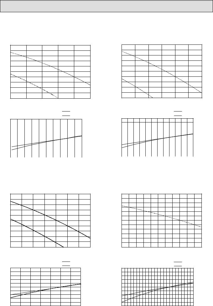
5-3. FAN PERFORMANCE AND CORRECTED AIRFLOW
PE-8GAK(T) |
PE-10GAK(T) |
Fan Performance |
Fan Performance |
|
(Pa) |
|
|
|
(Pa) |
|
|
|
|
250 |
|
|
|
250 |
|
|
|
pressure |
200 |
|
|
pressure |
200 |
|
|
|
150 |
|
|
150 |
|
|
|
||
static |
|
|
static |
|
Hi |
|
||
|
|
Hi |
|
|
|
|||
External |
|
|
External |
|
|
|
||
100 |
|
|
100 |
|
|
|
||
|
|
|
|
|
|
|
||
|
Lo |
|
|
|
|
|
|
|
|
50 |
|
|
|
50 |
Lo |
|
|
|
0 |
|
|
|
0 |
|
|
|
|
50.0 |
60.0 |
70.0 (CMM) |
|
60.0 |
70.0 |
80.0 |
90.0 (CMM) |
|
|
Airflow |
|
|
|
|
Airflow |
|
|
Corrected Airflow |
|
Capacity |
|
Corrected Airflow |
|
Capacity |
|
|
|
Input |
|
|
Input |
|||
|
1.1 |
|
|
|
1.1 |
|
|
|
|
|
|
|
|
|
|
|
|
/input factor |
|
|
|
|
|
|
/input factor |
1.0 |
|
|
|
|
|
|
|
|
|
|
|
|
|
|
|
|
|
|
|
|
|
|
|
||||
|
|
|
|
|
|
|
|
|
|
|
|
|
|
||||
|
|
|
|
|
|
|
|
|
|
|
|
|
|
||||
|
|
|
|
|
|
|
|
|
|
|
|
|
|
||||
|
|
|
|
|
|
|
|
|
|
|
|
|
|
||||
|
|
|
|
|
|
|
|
|
|
|
|
|
|
||||
1.0 |
|
|
|
|
|
|
|
|
|
|
|
|
|
|
|
|
|
Capacity |
|
|
|
|
|
|
Capacity |
0.9 |
|
|
|
|
|
|
|
|
|
|
|
|
|
|
|
|
|
|
|
|
|
|
|
||||
|
|
|
|
|
|
|
|
|
|
|
|
|
|
||||
|
|
|
|
|
|
|
|
|
|
|
|
|
|
||||
|
|
|
|
|
|
|
|
|
|
|
|
|
|
||||
|
|
|
|
|
|
|
|
|
|
|
|
|
|
||||
|
|
|
|
|
|
|
|
|
|
|
|
|
|
||||
0.9 |
|
|
|
|
|
|
|
|
|
|
|
|
|
|
|
||
|
|
|
|
|
|
|
|
|
|
|
|
|
|
|
|||
|
|
|
|
|
|
|
|
|
|
|
|
|
|
|
|||
|
|
|
|
|
|
|
|
|
|
|
|
|
90 (CMM) |
||||
|
|
|
|
|
|
|
|
|
|
|
|
|
|||||
|
|
|
|
|
|
|
60 |
65 |
70 |
75 |
80 |
85 |
|||||
45 |
50 |
55 |
60 |
65 |
70 (CMM) |
||||||||||||
|
|
|
|
|
|
|
|
|
|||||||||
|
|
|
|
Airflow |
|
|
|
|
|
|
|
Airflow |
|
|
|
|
|
|
PE-12GAK(T) |
|
PE-16GAK(T) |
|
Fan Performance |
|
Fan Performance |
|
|
|
(Pa) |
|
250 |
|
300 |
pressure |
200 |
pressure |
250 |
|
|||
150 |
200 |
||
|
|
|
|
static |
Hi |
static |
150 |
External |
100 |
External |
|
|
|
|
|
|
|
|
100 |
|
Lo |
|
|
|
50 |
|
|
|
|
|
|
|
|
|
|
|
|
50 |
|
|
|
|
|
|
|
|
|
|
|
|
|
|
0 |
|
|
|
|
|
|
|
100.0 (CMM) |
0 |
|
|
|
|
|
|
|
|
|
|
|
|
|
|
65.0 |
70.0 |
75.0 |
|
80.0 |
85.0 |
90.0 |
95.0 |
80.0 |
|
90.0 |
|
100.0 |
|
110.0 |
120.0 |
|
130.0 |
(CMM) |
||||
|
|
|
|
|
Airflow |
|
|
|
|
|
|
|
|
|
|
Airflow |
|
|
|
|
|
|
|
|
Corrected Airflow |
|
|
|
Capacity |
|
Corrected Airflow |
|
|
|
|
|
Capacity |
|
|||||||||
|
|
|
|
Input |
|
|
|
|
|
|
Input |
|
|
||||||||||
|
1.1 |
|
|
|
|
|
|
1.1 |
|
|
|
|
|
|
|
|
|
|
|
||||
|
|
|
|
|
|
|
|
|
|
|
|
|
|
|
|
|
|
|
|
|
|
||
coefficient |
1.0 |
|
|
|
|
|
|
|
/ input factor |
1.0 |
|
|
|
|
|
|
|
|
|
|
|
|
|
Correction |
|
|
|
|
|
|
|
|
Capacity |
|
|
|
|
|
|
|
|
|
|
|
|
|
|
|
0.9 |
|
|
|
|
|
|
|
|
0.9 |
85 |
90 |
95 |
100 |
105 |
110 |
115 |
120 |
125 |
130 |
135 |
140 (CMM) |
|
|
65 |
70 |
75 |
80 |
85 |
90 |
95 |
100 |
(CMM) |
80 |
|||||||||||||
|
|
|
|
|
|
|
|
|
|
|
|
|
|
|
|||||||||
|
|
|
|
Airflow |
|
|
|
|
|
|
|
|
|
Airflow |
|
|
|
|
|
|
|||
|
|
|
|
|
|
|
|
|
18 |
|
|
|
|
|
|
|
|
|
|
|
|
|
|
 Loading...