

Page 1
Service Bulletin List
No. Subject Date
MSB-97E26-001 CHANGE OF FRONT ROTOR FOR ABS
EQUIPPED VEHICLES (REVICED)
MSB-97E37-003 CHANGE IN TIE ROD NUT TIGHTENING TORQUE
VALUES
MSB-97E52-001 ADDITION OF SRS AIR BAG MAINTENANCE
PROCEDURE
MSB-98E00-011 CHANGE IN YEAR MODEL FOR ´99 PAJERO 1998-10-15
MSB-98E27-001 CHANGE OF ABS REAR ROTOR 1998-06-15
MSB-98E37-002 NEW SERVICE PROCEDURE FOR POWER
STEERING GEARBOX
MSB-98E42-502 CORRECTING MINIMUM ENTRAPMENT AMOUNT
FOR POWER WINDOW WITH SAFETY
MECHANISM
MSB-98E54-002 CORRECTION TO ELC 4-SPEED AUTOMATIC
TRANSMISSION CIRCUIT
MSB-99E11-502 CORRECTION OF 4M40 ENGINE IDLE UP SPEED
(FOR ANTI-SKID BRAKE)
MSB-99E16-001 CHANGE OF GLOW PLUG 2000-04-15
MSB-00E31-001 WHEEL BALANCE ADJUSTMENT PROCEDURE 2000-07-15
MSB-00E35-001 CHANGE TO ERASING OF ABS DIAGNOSTIC
CODES
MSB-00E37-501 ADDITION OF STEERING ANGLE ADJUSTMENT
PROCEDURE
1997-12-05
1998-01-16
1997-04-30
1999-08-15
1998-11-30
1998-11-30
1999-11-15
2000-05-30
2000-12-30
Page 2
SERVICE BULLETIN
OVERSEAS SERVICE DEPT. MITSUBISHI MOTORS CORPORATION
SERVICE BULLETIN
Subject:
WHEEL BALANCE ADJUSTMENT PROCEDURE ALL MODELS 00-00
MSB-00E31-001
No.:
:
2000-07-15
Date
QUALITY INFORMATION ANALYSIS
<Model> <M/Y>
Group:
INFORMATION/
CORRECTION
1. Description:
There have been cases where the troubles failed to be removed completely because of incorrect
balancer machine handling or use of an inaccurately calibrated balancer machine. This Service
Bulletin informs you of the cautions to be taken when handling a balancer machine and the
balance check procedures to prevent such a case from recurring in a dealer.
2. Details:
To solve the problems caused by steering or body vibrations, it is essential to balance the wheels
and tires accurately. For this, the wheel and tire must be accurately centered with respect to the
balancer shaft, and the balancer must also be calibrated accurately.
WHEEL & TIRES
INTERNATIONAL
CAR
ADMINISTRATIO
OFFICE
Draft No.:
T.NITTA - PROJECT LEADER
AFTER SALES SERVICE & CS PROMOTION
99AL121708
Page 3
Procedures
1. Check to ensure that the balancer cone and the cone-contacting portion of the wheel are free from any
dirt, corrosion and damage.
Remove all balance weights attached, stones caught in the tire grooves and mud adhered from th
2.
wheel and tire.
Install the wheel and tire to the balancer in the following procedure:
3.
Caution:
The socket diameter of a Mitsubishi genuine wheel is
•
and
107.5 mm (4.23 in) the other types of vehicle. Be sure to use the balancer cone
ɸɸɸɸ
matching the socket diameter.
Use the black-mounted cone to secure the wheel to the balancer if possible. If installable i
•
this method, go to Step 4.
If the socket diameter of the wheel is too large to secure it with the back-mounted cone,
•
secure the wheel to the balancer with the front mounting cone. If the wheel is to be secured in
this way, go to Step 6.
Do not use the log nut hole mounting method because it does not allow the accurat
•
centering of the wheel.
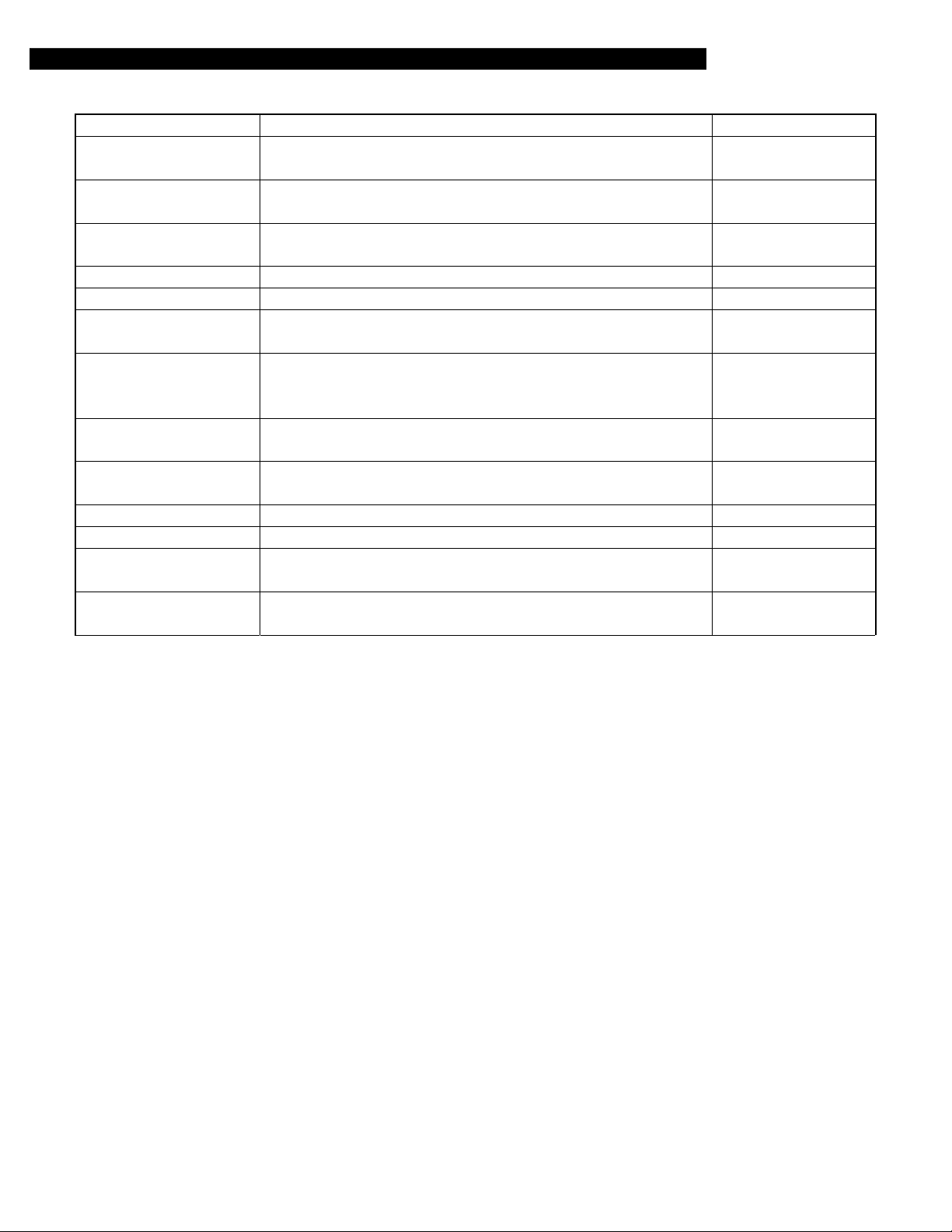
4. When securing with back-mounted cone:
Operate the balancer to measure the imbalance, an attach weight in accordance with the
measurements.
Caution: Be sure to drive the weight straight in the wheel.
67.0 mm (2.64 in) for passenger cars
ɸɸɸɸ
HUB/SHAFT
ASSEMBLY
SPRING PLATE
WHEEL
MOUNTING
CONE
CLAMPING CUP
STANDARD WHEEL
RIM
WING NUT
X0043BY
5. Loosen the wing nut, rotate the wheel half a turn (180°) and tighten the nut again. Then, perform the
measurement again to confirm that the wheel is in balance. If not in balance, check if the balancer is
correctly calibrated. Go to Step 11.
2
Page 4
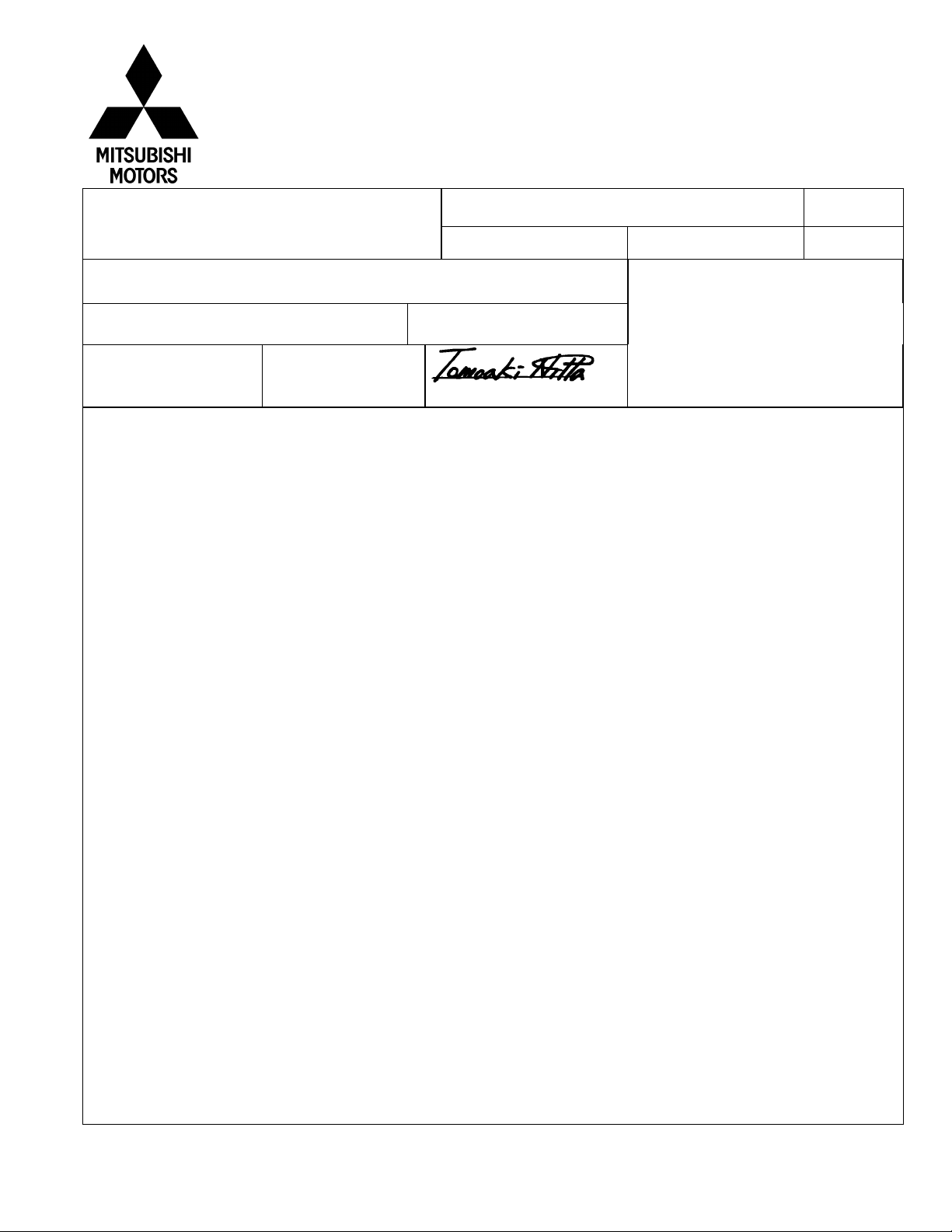
6. When securing with front-mounted cone:
Caution:
When pressing in the cone by tightening the wing nut slowly, hold the tire by hand such that
•
the wheel may contact the spring plate of the balancer evenly.
If this work is not performed with care, the wheel would fail to be centered correctly.
•
Futhermore, the cone-contacting area of the wheel would deform, preventing subsequent
wheel balancing from being performed accurately.
Operate the balancer to measure the imbalance. Mark the point attributable to the imbalance with a
piece of chalk.
(Do not attach any balance weight.)
PRESSURE
RING
WING NUT
HUB/SHAFT-ASSEMBLY
SPRING PLATE
LIGHT TRUCK
MOUNTING CONE
LIGHT TRUCK RIM
X0044BY
7. Loosen the wing nut, rotate the wheel half a turn (180°) and tighten the wing nut carefully again. Then,
perform the measurement again.
8. Repeat the measurement three times in the same manner, and take either of the following measures
according to the measurement again.
Caution: Be sure to drive the weight straight in the wheel.
If the results are the same in all measurements, attach a weight according to the indication on th
a.
machine.
b. If the weight difference among the three measurements is less than 0.5 oz and the thre indicated
points are all within a range of less than 8 inch (30°), attach a weight having the average weight at
the mean position.
c. If the weight difference among the three measurements is 0.5 oz or more or if the indicate
positions are not within a range of less than 8 inch (30°), check if th balancer is correctly calibrated.
Go to step 11.
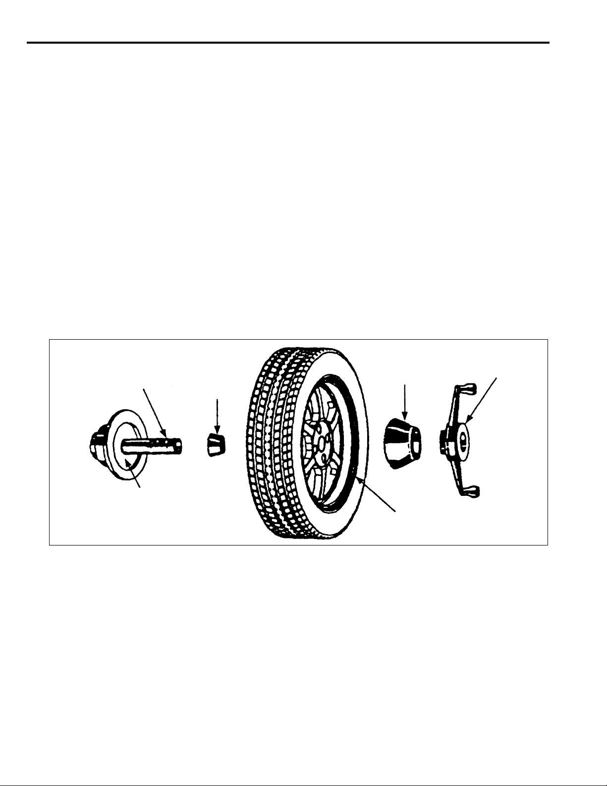
9. Reinstall the tire to the vehicle, and perform a driving
WHEEL
test. If the tire still generates vibration, perform the Ste
10.
10. Attach the adapter (MB991820) on the back side of th
MB991820
wheel, and install the wheel onto the machine using the
back-mounted cone. Then, perform the balance
adjustment again. For the procedure, refer to Steps 4
and 5
Caution Check to ensure that the contactin
portions of the adapter, wheel and
balancer are free from any dirt, corrosion
and damage.
WHEEL
MOUNTING
CONE
CLAMPING
CUP
HUB/SHAFT
ASSEMBLY
X0045BY
3
Page 5

11. Checking for calibration.
Check your balancer’s calibration approximately every 100 balances. Your whee balancer’s instruction
manual should include calibration procedures. If the calibration procedures specifically for your balancer
are missing, use following steps for zero calibration, static balance, and dynamic balance checks. Th
wheel balancer calibration checks are also described in the flowchart on next page.
a. Mount an undamaged original-equipment alloy rim and tire assembly (wheel) onto your off-the-car
wheel balancer. Balance the wheel.
b.
Zero Calibration Check.
Loosen the balancer wing nut, rotate the wheel a half-turn (180°), and
retighten the nut. Recheck the balance.
i)
If the imbalance is 5 grams or less, the zero calibration is OK. Rebalance the wheel, then g
to Step d to check the static balance.
ii)
If the imbalance is more than 5 grams, go to Step c.
c. Loosen th balancer wing nut, rotate the wheel ¼ turn (90°), and retighten the nut. Recheck th
wheel balance
i)
If the imbalance is 5 grams or less, the wheel may not be centered on th balancer, or the
balancing cones, the cup, and/or wing nut are damaged, dirty, or inappropriate for the wheel.
You may need to refer to th balancer manufacturer’s instructions to verify the correct
attachments. After making the necessary correction, recheck the wheel balance. If OK, then
go to Step d.
ii)
If the imbalance is more than 5 grams, th balancer requires calibration, Contact th balancer
manufacturer for calibration by their repair representative.
d.
Static Balance Check.
Attach a 5-gram weight to the outer rim. Recheck the balancer. The
balancer should detect 5±2 grams of imbalance 170° to190° away from the 5-gram weight.
i)
If the imbalance is within specification, the static balance calibration is correct, Go to Step e
to check the dynamic balance.
ii)
If the imbalance is out of specification, th balancer requires calibration. Contact th balancer
manufacturer for calibration by their repair representative.
e.
Dynamic Balance Check.
Attach a 5-gram weight to the inner rim at 180° opposite the 5-gram
weight that was added in Step d. Recheck the balance. Th balancer should detect 5±2 grams of
imbalance 170° to 190° away from both the inner and outer 5-gram weights.
i)
If the imbalance is within specification, the dynamic balance calibration is correct. Th
balancer calibration checks are complete.
ii)
If the imbalance is out of specification, th balancer requires calibration. Contact th balancer
manufacturer for calibration by their repair representative.
4
Page 6
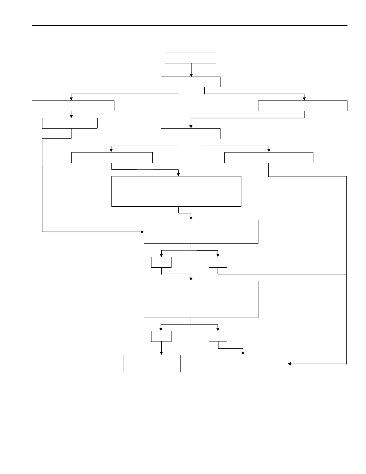
WHEEL BALANCER CALIBRATION CHECKS
Balance Wheel
Rotate wheel ½ turn
Imbalance is 5 grams or less Imbalance = more than 5 grams
Rebalance wheel
Rotate wheel ¼ turn
Imbalance = 5 grams or less Imbalance = more than 5 grams
Verify wheel is properly centered. Verify
cones, cup & wing nut are clean, undamaged &
appropriate for wheel. Make necessary
corrections, then recheck wheel balance
Attach a 5-gram weight to the rim.
Is the imbalance 5 ± 2 grams at 170-190
degrees away from the 5-gram weight?
(Zero Calibration Check)
(static balance Check)
YES NO
Attach a 5 gram weight to the inner rim
180 degrees opposite the weight on the
outer rim. Is the imbalance 5± 2 grams at
170-190 degrees away from both 5-gram
weights?
YES NO
Balancer does not
require calibration.
(Dynamic Balance Check)
Balancer requires calibration.
Contact balancer manufacturer.
5
Page 7
SERVICE BULLETIN
QUALITY INFORMATION ANALYSIS
OVERSEAS SERVICE DEPT. MITSUBISHI MOTORS CORPORATION
MSB-00E35-001
SERVICE BULLETIN
Subject:
Group:
INFORMATION/
CORRECTION
1. Description:
This Service Bulletin informs you of erasing of the diagnostic codes for the cars mentioned below
that are equipped with the ABS-ECU
2. Applicable Manuals:
CHANGE TO ERASING OF ABS DIAGNOSTIC
CODES
SERVICE BRAKE
INTERNATIONAL
CAR
ADMINISTRATIO
OFFICE
No.:
:
2000-05-30
Date
Draft No.:
T.NITTA - PROJECT LEADER
AFTER SALES SERVICE & CS PROMOTION
99AL122308
<Model>
(EC)COLT/LANCER
(CKOA,CJOA)
(EC)PAJERO
(V10, 20, 30,40)
(EC)L400
(PA0 to PD0)
(EC)PAJERO
SPORT/MONTERO
SPORT
(K80W, K90W)
(EC)L200 (K60, k70)
<M/Y>
96-10
95-10
95-10
99-10
97-10
Manual Pub. No. Language Page(s)
’96 COLT/LANCER PWME9511 (English) 35-6
Workshop Manual Chassis PWMS9512 (Spanish)
PWMF9513 (French)
PWMG9514 (German)
PWMD9515 (Dutch)
PWMW9516 (Swedish)
’95 PAJERO PWJE9086-F (English) 35-36-4
Workshop Manual Chassis Supplement PWJF9088-F (French)
PWJG9089-F (German)
PWJD9090-F (Dutch)
PWJW9091-F (Swedish)
’95 MONTERO
PWJS9087-F (Spanish) 35-36
Workshop Manual Chassis Supplement
’95 L400 PWWE9410 (English) 35B-7
Workshop Manual Chassis PWWS9411 (Spanish)
PWWF9412 (French)
PWWG9413 (German)
PWWD9414 (Dutch)
PWWW9415 (Swedish)
’99 PAJERO SPORT PWJE9812 (English) 35B-4,5
Workshop Manual Chassis PWJF9814 (French)
PWJG9815 (German)
’99 MONTERO SPORT
PWJS9813 (Spanish) 35B-4,5
Workshop Manual Chassis
Page 8
Manual Pub. No. Language Page(s)
’97 L200 PWTE96E1 (English) 35b-5
Workshop Manual Chassis PWTS96E1 (Spanish)
PWTF96E1 (French)
PWTG96E1 (German)
2000 L200 PWTE96E2 (English) 35b-5
Workshop Manual Chassis PWTS96E2 (Spanish)
PWTF96E2 (French)
PWTG96E2 (German)
3. Effective date:
Model Effective Date ABS-ECU part No.
COLT/LANCER From March 1998 MR445910
PAJERO/MONTERO From September 1998 MR400413
L400 From September 1998 MR400415
PAJERO SPORT/
MONTERO SPORT
From the first production car MR235362*, MR307755*,
MR334886*
L200 From September 1998 MR400416, MR400417,
MR4469642*
* Integral Hydraulic unit. These part numbers are for the hydraulic unit.
4. Details:
’96 COLT/LANCER Workshop Manual Chassis (page 3.)
’95 PAJERO Workshop Manual Chassis Supplement (page 5.)
’95 L400 Workshop Manual Chassis (page 7.)
’99 PAJERO SPORT Workshop Manual Chassis (page 9.)
’97 L200 Workshop Manual (page 11.)
’00 L200 Workshop Manual (page 13.)
2
Page 9
SERVICEBRAKES –
ABS Troubleshooting <Vehicles built from June,1994
4. Remedy the malfunctions indicated by th
diagnosis codes, disconnect the diagnosis code
check harness, and then install the valve relay.
Then turn the ignition switch to ON again t
check the ABS warning lamp. (Refer to P.35-36-
16.) If the lamp indicates a malfunction, th
valve relay system may be detective. (Refer to
P.35-36-14.)
ERASING DIAGNOSIS CODES
<Old>
With the MUT-II
Connect the MUT-II to the diagnosis connector (16pin), and then erase the diagnosis codes.
>
35-36-4
Without the MUT-II
Remove the battery cable from the battery (-)
terminal for 10 seconds or more, and the
reconnect the cable.
<New> See next page.
5
Page 10
<New>
With the MUT-II
Connect the MUT-II to the diagnosis connector (16-pin), then erase the diagnosis codes.
Caution
Turn the ignition switch off before connecting or disconnecting the MUT-II.
When diagnostic trouble codes (Nos. 21 to 24) (for vehicle wheel speed sensor system failures) occur,
normal MUT-II operation may not erase those codes. In that case, erase the diagnostic trouble codes
using the following procedures.
1. Perform erasing of the diagnostic trouble codes by special operation of the brake pedal. (See erasing
procedure for the diagnostic trouble codes without use of the MUT-II.)
2. Turn the ignition switch OFF.
3. Perform erasing of the diagnostic trouble codes by use of the MUT-II.
Without the MUT-II
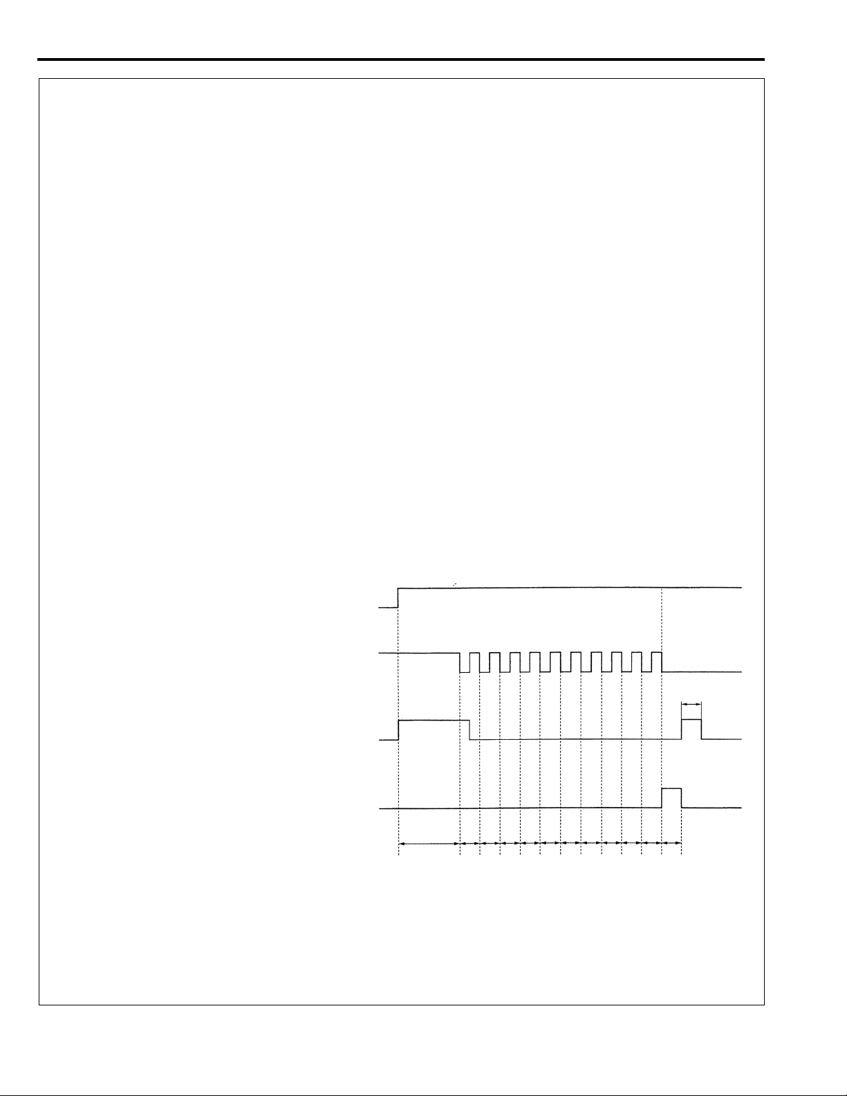
1. Stop the car.
2. Place the stop lamp switch to ON (with brake pedal depressed).
3. Under the condition of 1 and 2 above, turn the ignition switch ON. After that, place the stop lamp
switch to OFF (with brake pedal released) within 3 seconds, and cycle the stop lamp switch ON and
OFF ten times consecutively.
NOTE:
When ABS-ECU stops functioning through the fail-safe mechanism, erasing of the diagnostic troubl
codes cannot be performed.
Ignition switch
ON
OFF
Stop lamp switch
ON
OFF
1s
ABS warning lamp
ON
OFF
Diagnostic trouble code memory
Within 3
seconds
Within 1s
1st
Within 1s
2nd
Within 1s
3rd
Within 1s
4th
Within 1s
5th
Within 1s
6th
Within 1s
7th
Within 1s
8th
Within 1s
9th
Within 1s
10th
Erasing completed
AW0558AS
4. Ensure that the diagnostic trouble codes have been erased. When diagnostic trouble codes (Nos. 21
to 24) (for vehicle wheel speed sensor system failures) occur, the above procedures may not eras
those codes. In that case, turn the ignition switch OFF, then repeat steps 1 to 3 above.
6
Page 11
SERVICE BULLETIN
QUALITY INFORMATION ANALYSIS
OVERSEAS SERVICE DEPT. MITSUBISHI MOTORS CORPORATION
SERVICE BULLETIN
Subject:
Group:
INFORMATION/
CORRECTION
1. Description:
This Service Bulletin informs you that a cautionary description has been added on Steering Angle
Check.
2. Applicable Manuals:
PAJERO
Workshop Manual Chassis
MONTERO
Workshop Manual Chassis
PAJERO
Workshop Manual Chassis
’99 PAJERO SPORT
Workshop Manual Chassis
’99 MONTERO SPORT
Workshop Manual Chassis
Workshop Manual Chassis
’97 L200
Workshop Manual Chassis
’93 L200
Workshop Manual Chassis’97
ADDITION OF STEERING ANGLE
ADJUSTMENT PROCEDURE
STEERING
INTERNATIONAL
CAR
ADMINISTRATION
OFFICE
Manual Pub. No. Language Page(s)
Draft No.: 00SY040517
No.: MSB-00E37-501
Date: 2000-12-30 <Model> <M/Y>
(EC)PAJERO/
MONTERO
(V10, 20, 30, 40)
(EC)PAJERO
SPORT/MONTERO
SPORT
T.NITTA - PROJECT LEADER
AFTER SALES SERVICE & CS PROMOTION
PWJE9086 (English)
PWJS9087 (Spanish)
PWJF9088 (French)
PWJG9089 (German)
PWJD9090 (Dutch)
PWJW9091 (Swedish)
PWJE9812 (English)
PWJS9813 (Spanish)
PWJF9814 (French)’99 PAJERO SPORT
PWJG9815 (German)
PWTE96E1 (English) 37A-7
PWTS96E1 (Spanish)
PWTF96E1 (French)
PWTG96E1 (German)
PWTE9319 (English) 37-14
(K80W, K90W)
(EC)L200(K60, K70)
37-8
37A-7
00-10
99-10
93-10
3. Details:
Pajero Workshop Manual (PWJE 9086) (Page 2)
’99 PAJERO SPORT Workshop Manual Chassis (Page 3)
’93 L200 Workshop Manual Chassis (Page 4 to 5)
’97 L200 Workshop Manual Chassis (Page 6 to 7)
Page 12
37-8
STEERING – Service Adjustment Procedures
Pitman arm
80Nm
8kgm
58 ft.lbs.
Stopper
bolt
80Nm
8kgm
58 ft.lbs.
Stopper bolt
Idler arm
13AO295
13E005213E0053
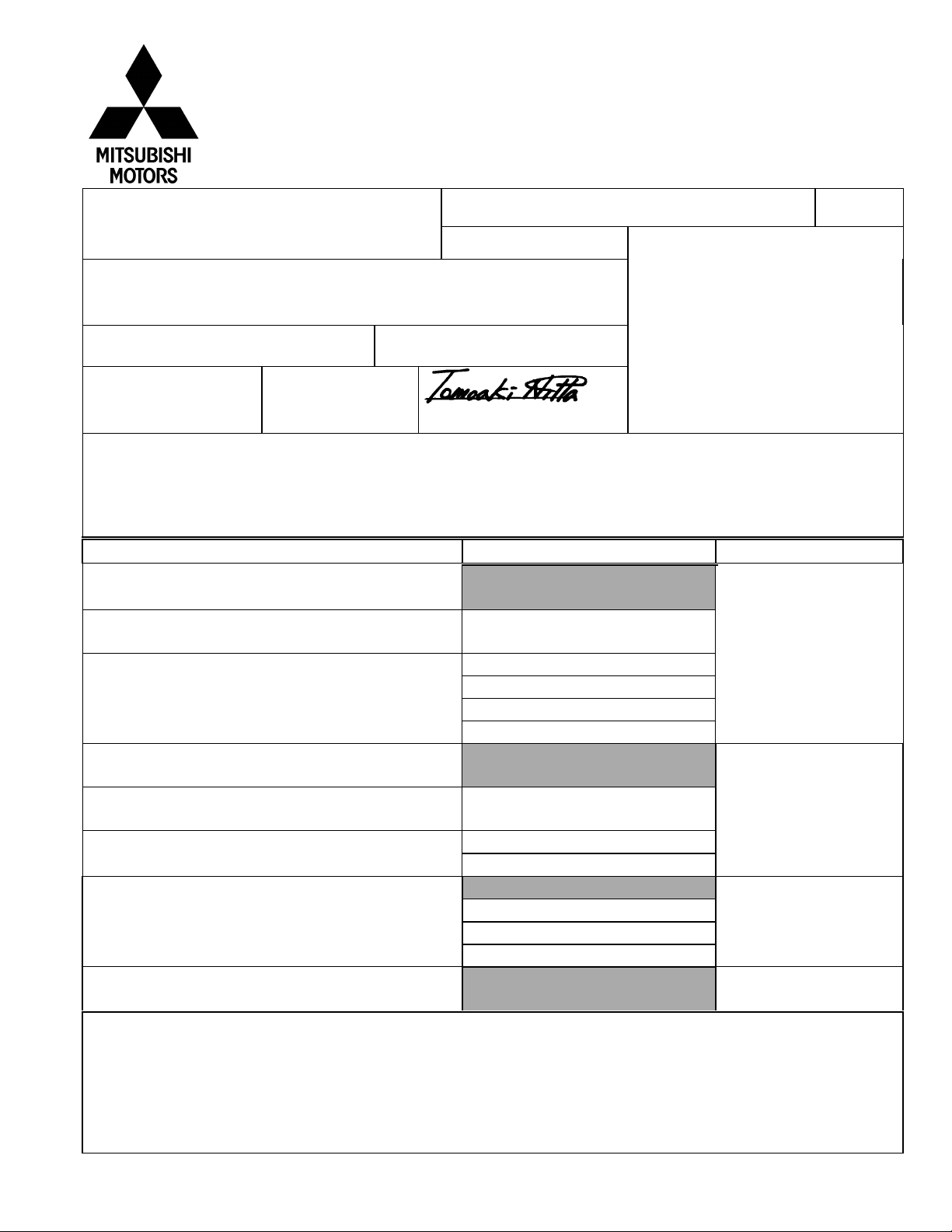
STEERING ANGLE CHECK
E37FDAH
1. Place the front whe el on a turn ing radius gauge and meas ure
the steering angle
Standard value: Inner wheel 32° 40’
0
-3°
Outer wheel 29° 45’
2. If the steering angle is outside the standard value, after
checking the toe-in, (Refer to GROUP 33-Service Adjustment
Procedures), adjust the steering angle with the stopper bolt.
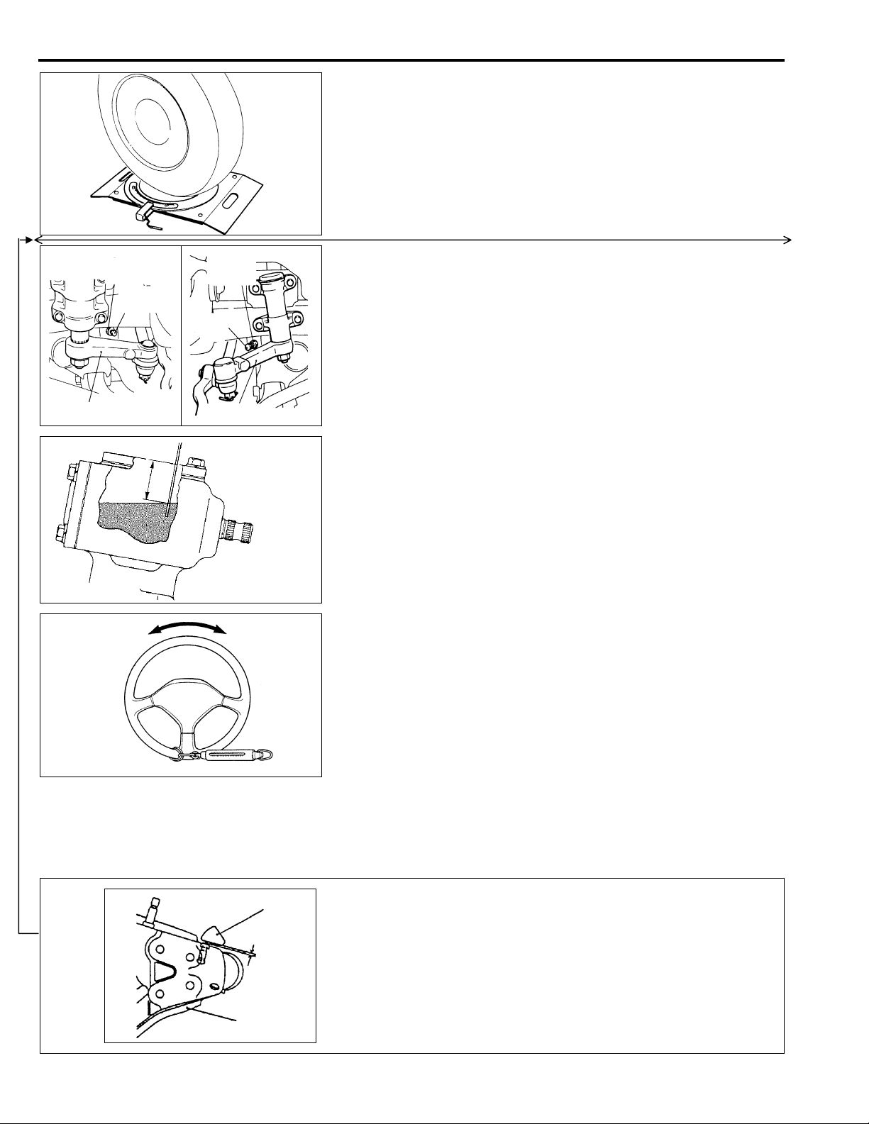
STEERING GEAR OIL LEVEL CHECK
(MANUAL STEERING)
Remove the breather plug and check the oi l level in the stee r ing
gear box by using a s pecial gauge or a thin screwdriver.
Standard value: 25 mm (0.98 in.)
E37FEAAa
<Added>
13W002
13E0035
Knuckle
1 mm or more
STATIONARY STEERING EFFORT CHECK
(POWER STEERING)
1. Place the vehicle on a level surface and place the steering
wheel in the straight-ahead position.
2. Set the engine spee d to 1,000 r/min.
Caution
After checking the engine r/min., there must be a return to
the standard idling r/min.
3. Measure the tangential force with a spri ng bal ance by turn ing
the steering wheel clockwise and counter clock wise one and a
half turns.
Standard value: 37N (3.7kg, 8.21 Ibs) or less
4. If the stationary steering effort exceeds the standard value,
check for belt slackness, damage, insufficient oil, air mixed into
oil, collapsed or twisted hoses, etc., and repair if found.
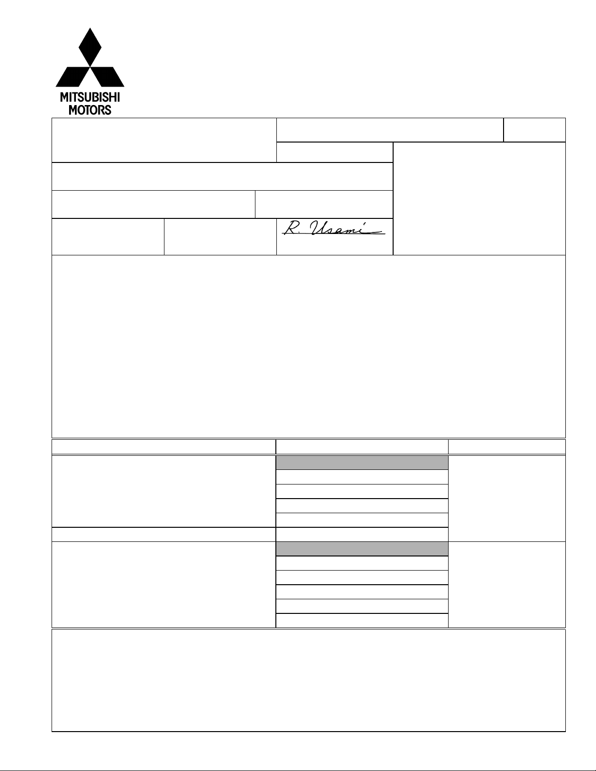
Caution
When the steering wheel is turned to lock, check
that the clearance between the knuckle and the
stopper is 1 mm or more.
E37FFAG
Lower arm
X0520AA
2
Page 13
SERVICE BULLETIN
QUALITY INFORMATION ANALYSIS
OVERSEAS SERVICE DEPT. MITSUBISHI MOTORS CORPORATION
MSB-97E26-001 REV
SERVICE BULLETIN
Subject:
Group:
INFORMATION
1. Description:
On the ABS equipped vehicles, the front rotor and the brake disc have been changed as follows:
(1) The front rotor has been changed to that made of sheet metal. Accordingly, bearing surface
has been added to the brake disc.
(2) The number of bolts used for mounting the front rotor has been changed form 2 to 4.
Accordingly, the bolt holes have been added to the bearing surface of the brake disc.
CHANGE OF FRONT ROTOR FOR ABS
EQUIPPED VEHICLES (REVICED)
FRONT AXLE
OVERSEAS
SERVICE
DEPT
No.:
:
1997-12-05
Date
Draftno:
96-SY-18
R. USAMI - MANAGER
QUALITY INFORMATION ANALYSIS
<Model> <M/Y>
(EC,EXP) L400
(PA0V)
(EC,EXP) PAJERO
(V10,V20,V30,V40)
97-10
97-10
2. Effective Date:
PAJERO/MONTERO
L400
3. Applicable Manuals:
Manual Pub. No. Language Page(s)
PAJERO Workshop Manual Chassis PWJE9086-F (English) 26-17
MONTERO Workshop Manual Chassis PWJS9087-F (Spanish)
’95 L400 Workshop Manual Chassis PWWE9410 (English) 26-18
Note:
This Service Bulletin makes correction of errors in and addition of interchangeability to the
previously published Service Bulletin MSB-97E26-001 (1997-02-28). The previous Service
Bulletin should be discarded.
From November 1996
From 1997 model year
PWJF9088-F (French)
PWJG9089-F (German)
PWJD9090-F (Dutch)
PWJW9091-F (Swedish)
PWWS9411 (Spanish)
PWWF9412 (French)
PWWG9513 (German)
PWWD9514 (Dutch)
PWWW9515 (Swedish)
4. Details:
PAJERO/MONTERO Workshop Manual, Page 2
’95 L400 Workshop Manual chassis, Page 3
Page 14
FRONT AXLE - Axle Hub
26-17
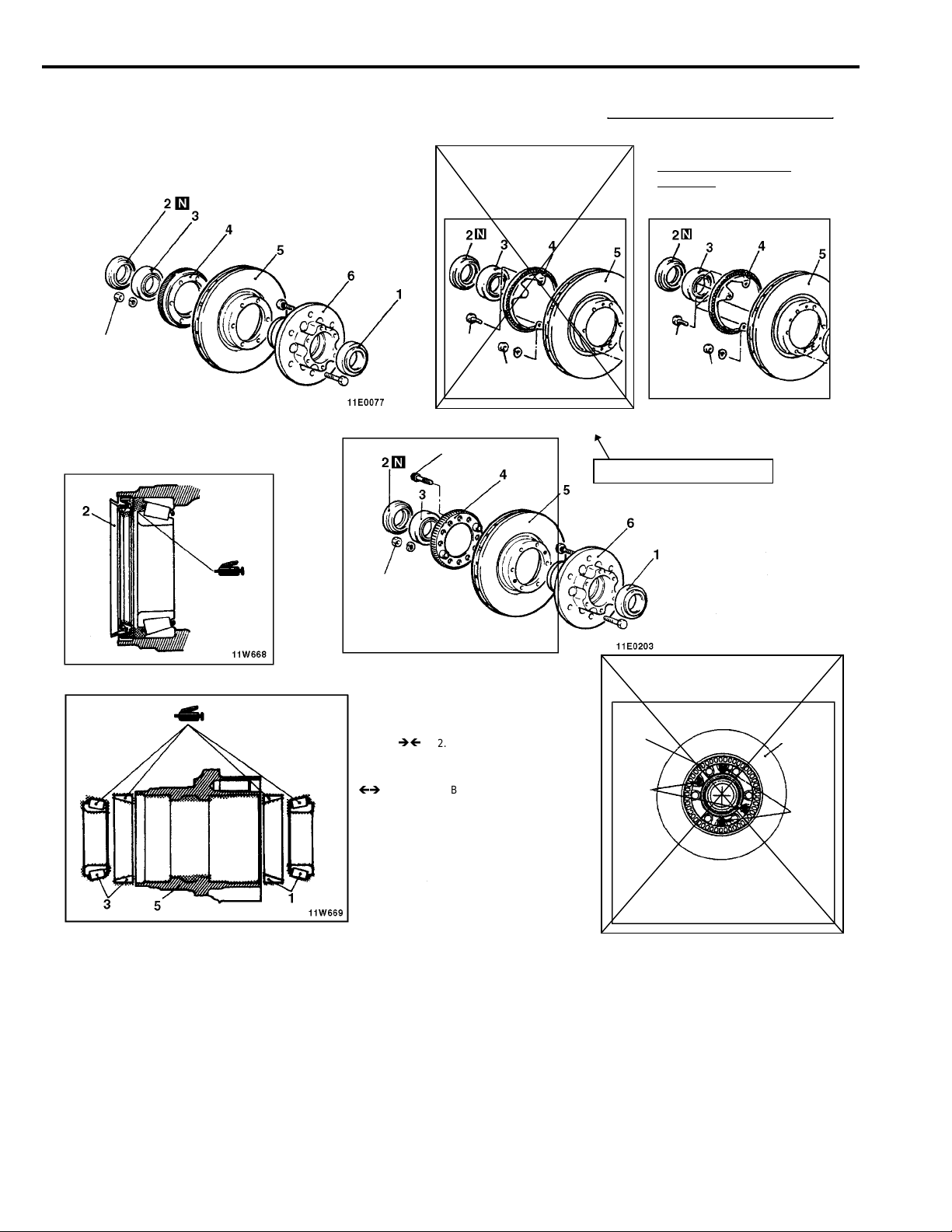
DISASSEMBLY AND REASSEMBLY (Front Axle Hub)
<New>
<Vehicles built up to May, 1994>
50-60 Nm
5.0-6.0 kgm
36-43 ft.lbs.
<Vehicles built from June, 1994>
Changed to be made of
sheet metal
<From November 1996>
22 Nm
2.2 kgm
16 ft.lbs.
50-60 Nm
5.0-6.0 kgm
36-43 ft.lbs.
13 Nm
1.3 kgm
9 ft.lbs.
<Deleted>
Up to October 1996
<New>
Two bolts changed to
<Deleted>
four bolts
<From November 1996>
22 Nm
2.2 kgm
16 ft.lbs.
50-60 Nm
5.0-6.0 kgm
36-43 ft.lbs.
<Added>
E26ll--
50-60 Nm
5.0-6.0 kgm
36-43 ft.lbs.
Disassembly steps
1. Outer bearing
2. Oil seal
3. Inner bearing
4. Rotor <Vehicles with ABS>
5. Brake disc
6. Front hub
<Deleted>
<Added>
<From November 1996>
Rotor
Tightening
by bolts
Note
When the rotor (2) is installed in the brake
disc (1), make sure that the rotor is aligned
with the bearing surface of the brake disc,
as shown.
Brake disc
Not
used
2
Page 15
SERVICE BULLETIN
OVERSEAS SERVICE DEPT. MITSUBISHI MOTORS CORPORATION
SERVICE BULLETIN
Subject:
CHANGE IN TIE ROD NUT TIGHTENING
TORQUE VALUES
MSB-97E37-003
No.:
:
1998-01-16
Date
QUALITY INFORMATION ANALYSIS
<Model> <M/Y>
(EC,EXP) PAJERO
(V10,V20,V30,V40)
93-10
Group:
INFORMATION
1. Description:
This Service Bulletin informs you that the tie rod nut tightening torque values have been changed.
2. Effective Date:
From July 1996
3. Applicable Manuals:
1983 PAJERO Workshop Manual PWJE8240 (English) 13A-3, 13A-20
1986 PAJERO Workshop Manual PWJE8508 (English) 37-5, 37-51
1986 MONTERO Workshop Manual PWJS8509 (Spanish) 37-5, 37-52
1986 PAJERO Workshop Manual PWJF8510 (French) 37-5, 37-52
1986 PAJERO Workshop Manual PWJG8511 (German) 37-5, 37-50
1986 PAJERO Workshop Manual PWJD8512 (Dutch) 37-5, 37-48
1986 PAJERO Workshop Manual PWJW8513 (Swedish) 37-5, 37-49
PAJERO Workshop Manual (Looseleaf edition) PWJE8817-D (English) 37-6, 37-45
PAJERO Workshop Manual (Looseleaf edition) PWJE9086-G (English) 37-42
MOTERO Workshop Manual (Looseleaf edition) PWJS9087-G (Spanish) 37-42
PAJERO Workshop Manual (Looseleaf edition) PWJF9088-G (French) 37-42
PAJERO Workshop Manual (Looseleaf edition) PWJG9089-G (German) 37-42
PAJERO Workshop Manual (Looseleaf edition) PWJD9090-G (Dutch) 37-42
PAJERO Workshop Manual (Looseleaf edition) PWJW9091-G (Swedish) 37-42
4. Details:
STEERING
OVERSEAS
SERVICE
DEPT
Manual Pub. No. Language Page(s)
Draftno:
96-SY-044
R. USAMI - MANAGER
QUALITY INFORMATION ANALYSIS
1983 PAJERO Workshop Manual, Page 2, 3
1986 PAJERO Workshop Manual, Page 4, 5
PAJERO Workshop Manual (Looseleaf edition), Page 6, 7
PAJERO Workshop Manual (Looseleaf edition), Page 8
Page 16
37-42
STEERING - Specifications
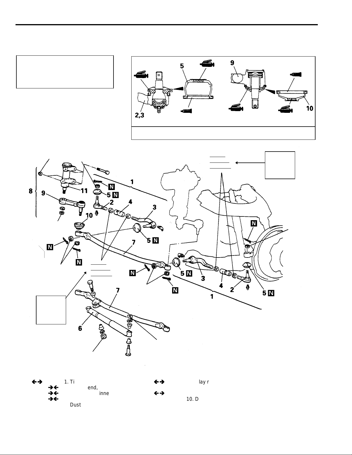
STEERING LINKAGE
REMOVAL AND INSTALLATION
Post-installation Operation
Adjustment of the Front Wheel
•
Alignment (Toe-in)
(Refer to GROUP 33 - Service
Adjustment Procedures.)
55 - 65 Nm
5.5 - 6.5 kgm
40 - 47 ft.lbs.
45 Nm
4.5 kgm
33 ft.lbs.
13E0006
Sealant: 3M ATD Part No. 8661 or equivalent
<Old>
73 Nm
7.3 kgm
53 ft.lbs.
E37VA..
13E0005
<New>
95 Nm
9.5 kgm
69 ft.lbs.
140 Nm
14 kgm
101 ft.lbs.
45 Nm
4.5 kgm
33 ft.lbs.
<New>
95 Nm
9.5 kgm
69 ft.lbs.
73 Nm
7.3 kgm
53 ft.lbs.
35 Nm
3.5 kgm
25 ft.lbs
Removal steps
1. Tie rod assembly
2. Tie rod end, outer 8. Idler arm (complete)
3. Tie rod end, inner
4. Pipe 10. Dust cover
5. Dust cover 11. Idler arm support
6. Damper
<Old>
45 Nm
4.5 kgm
33 ft.lbs.
35 Nm
3.5 kgm
25 ft.lbs
7. Relay rod
9. Idler arm
45 Nm
4.5 kgm
33 ft.lbs.
13E0073
8
Page 17
SERVICE BULLETIN
OVERSEAS SERVICE DEPT. MITSUBISHI MOTORS CORPORATION
SERVICE BULLETIN
Subject:
Group:
ADDITION OF SRS AIR BAG MAINTENANCE
PROCEDURE
INTERIOR
No.:
Date
Draftno:
QUALITY INFORMATION ANALYSIS
MSB-97E52-001
:
1997-04-30
96-AL-022
<Model> <M/Y>
ALL MODELS 91-10
INFORMATION
1. Description:
In the SRS air bag troubleshooting, items of cause of trouble in the inspection procedure for each
diagnostic trouble code, have been added.
2. Applicable Vehicles:
• ‘91~’10 SIGMA
• ‘92~’10 3000GT
• ’91~’10 COLT/LANCER
• ‘93~’10 GALANT
• ‘92~’10 SPACE RUNNER/SPACE WAGON
• ‘95~’10 L400
• ‘91~’10 PAJERO/MONTERO
• ‘97~’10 L200
3. Applicable Manuals:
SIGMA Workshop Manual chassis PWGE9004-G (English) 52B-14
3000GT Workshop Manual chassis PWUE9119-D (English) 52B-12
’97 3000GT Workshop Manual chassis
Supplement
COLT/LANCER Workshop Manual chassis PWME9117-D (English) 52B-12
OVERSEAS
SERVICE
DEPT
Manual Pub. No. Language Page(s)
QUALITY INFORMATION ANALYSIS
PWGS9005-F (Spanish)
PWGF9006-F (French)
PWGG9007-F (German)
PWGD9008-F (Dutch)
PWGW900-F (Swedish)
PWUE9119-F (English) 52B-6
PWMS9118-D (Spanish)
PWMF9119-D (French)
PWMG9120-D (German)
PWMD9121-D (Dutch)
PWMW9122-D (Swedish)
R. USAMI - MANAGER
Page 18
Manual Pub. No. Language Page(s)
95’COLT/LANCER Workshop Manual PWME9117-E (English) 52B-7
chassis Supplement PWMS9118-E (Spanish)
PWMF9119-E (French)
PWMG9120-E (German)
PWMD9121-E (Dutch)
PWMW9122-E (Swedish)
’97 COLT/LANCER Workshop Manual PWME9117-F (English) 52B-5
chassis Supplement PWMS9118-F (Spanish)
PWMF9119-F (French)
PWMG9120-F (German)
PWMD9121-F (Dutch)
PWMW9122-F (Swedish)
’96 COLT/LANCER Workshop Manual PWME9511 (English) 52B-8
chassis PWMS9512 (Spanish)
PWMF9513 (French)
PWMG9514 (German)
PWMD9515 (Dutch)
PWMW9516 (Swedish)
GALANT Workshop Manual chassis PWDE9211-B (English) 52B-13
PWDS9212-B (Spanish)
PWDF9213-B (French)
PWDG9214-B (German) 52B-11
PWDD9215-B (Dutch) 52B-13
PWDW9216-B (Swedish)
’96 GALANT Workshop Manual PWDE9211-D (English) 52B-7
chassis Supplement PWDS9212-D (Spanish)
PWDF9213-D (French)
PWDG9214-D (German)
PWDD9215-D (Dutch)
PWDW9216-D (Swedish)
SPACE RUNNER/SPACE WAGON PWDE9104-D (English) 52B-9
Workshop Manual chassis PWDS9105-D (Spanish)
PWDF9106-D (French)
PWDG9107-D (German)
PWDD9108-D (Dutch)
PWDW9109-D (Swedish)
’95 SPACE RUNNER/SPACE WAGON PWDE9104-E (English) 52B-8
Workshop Manual chassis Supplement PWDS9105-E (Spanish)
PWDF9106-E (French)
PWDG9107-E (German)
PWDD9108-E (Dutch)
PWDW9109-E (Swedish)
Page 19

Manual Pub.No. Language Page(s)
’97 SPACE RUNNER/SPACE WAGON PWDE9104-G (English) 52B-6
Workshop Manual chassis Supplement PWDS9105-G (Spanish)
PWDF9106-G (French)
PWDG9107-G (German)
PWDD9108-G (Dutch)
PWDW9109-G (Swedish)
’95 L400 Workshop Manual chassis PWWE9410 (English) 52B-9
PWWS9411 (Spanish)
PWWG9412 (French)
PWWG9413 (German)
PWWD9415 (Dutch)
PWWW9416 (Swedish)
’97 L400 Workshop Manual PWWE9410-B (English) 52B-5
chassis Supplement PWWS9411-B (Spanish)
PWWG9412-B (French)
PWWG9413-B (German)
PWWD9415-B (Dutch)
PWWW9416-B (Swedish)
PAJERO Workshop Manual chassis PWJE9086-F (English) 52B-10
MONTERO Workshop Manual chassis PWJS9087-F (Spanish)
PAJERO Workshop Manual chassis PWJF9088-F (French)
PWJG9089-F (German)
PWJD9090-F (Dutch)
PWJW9091-F (Swedish)
’96 PAJERO Workshop Manual
chassis Supplement
’96 MONTERO Workshop Manual
chassis Supplement
’96 PAJERO Workshop Manual PWJF9088-G (French)
chassis Supplement PWJG9089-G (German)
’97PAJERO Workshop Manual
chassis Supplement
’97 MONTERO Workshop Manual
chassis Supplement
’97 PAJERO Workshop Manual
chassis Supplement
’97 L200 Workshop Manual chassis PWTE96E1 (English) 52B-8
PWJE9086-G (English) 52B-10
PWJS9087-G (Spanish)
PWJD9090-G (Dutch)
PWJW9091-G (Swedish)
PWJE9086-H (English) 52B-6, 52B-7
PWJS9087-H (Spanish)
PWJF9088-H (French)
PWJG9089-H (German)
PWJD9090-H (Dutch) 52B-7
PWJW9091-H (Swedish) 52B-6, 52B-7
Page 20

SRS - Troubleshooting
52B-10
Code No.
21 or 22
(Comment)
(1) These diagnosis codes are output if there is abnormal resistance between the input
terminals of the air bag module (squib).
The trouble causes for each code No. are as follow
Code No. Trouble Symptom
21
22
(2) Diagnosis codes 21 and 22 are sometimes generated in combination with malfunction
codes relating to the front impact sensor (code Nor. 11, 12 and 13), but sometimes only
one should also be inspected at the same time.
The relationships between the codes are as follows.
Air bag module Short 11 or 21 12 or 21 13 or 21
(squib) Open circuit 11 or 22 12 or 22 13 or 22
Air bag module (squib) system Probable cause
Short in air bag module (squib) or harness short
•
Short in clock spring
•
Short in air bag module (squib) or front impact sensor harnesses
•
leading to the power supply
Open circuit in air bag module (driver’s side squib) or open harness
•
Open circuit in clock spring
•
Disconnected connector in the driver’s side air bag module (squib)
•
Open-circuit in clock spring due to inappropriate neutral position
•
Malfunction of connector contact
•
Short in air bag module (squib) or front impact sensor harnesses
•
leading to the power supply
Front impact sensor
Short Open circuit
(1 sensor)
Open circuit
(2 sensors)
Malfunction of clock spring
•
Open circuit in clock spring due to
•
inappropriate neutral position
Malfunction of harness or con-
•
nectors
Malfunction of air bag module
•
(squib)
Malfunction of SDU
•
<Added>
SDU
Battery
Insulating tape
Lock lever
Lock spring
Battery (-) cable
19E0164
Screwdriver
19X0353
1. Turn the ignition key to the “LOCK” position, disconnect the negative
battery cable and tape the terminal.
Caution
Wait at least 60 seconds after disconnecting the battery cable
before doing any further work. (Refer to P. 52B-4)
2. Remove the floor console assembly. (Refer to GROUP 52A - Floor
Console.)
3. Place a flat-tipped (-) screwdriver against the lock spring (metal portion)
of the SDU connector lock lever, and push the spring horizontally toward
the inside of the unit.
Caution
1. Do not use excessive force to raise the lock lever (green)
2. do not insert the screwdriver into the gap between the lock lever
(green) and the lock spring (metal portion).
4. Disconnect the red 14-pin connector from the SDU.
19
Page 21

52B-10
g
SRS - Troubleshooting
Code No. 21 or 22 Driver’s air bag module (squib) system Probable cause
•
(1) These diagnosis codes are output if there is abnormal resistance between the
input terminals of the driver’s air bag module (squib) .
Refer to table 1 for the conditions for output of each diagnosis code.
(2) Diagnosis codes 21 and 22 are sometimes generated in combination with
diagnosis codes relating to the front impact sensor (code Nos. 11, 12 and 13), but
sometimes only one may be output instead of both being memorised. Because of
this, the front impact sensor should also be inspected al the same time.
Refer to table 2 for the failure mode combinations.
malfunction of clock spring
•
Open-circuit in clock spring due to inappropriate
neutral position
•
Malfunction of harnesses or connectors
•
Malfunction of air bag module (driver’s side squid)
•
Malfunction of SDU
TABLE 1: CONDITIONS FOR OUTPUT OF EACH DIAGNOSIS CODE
Code No. Trouble symptoms
•
21
22
Short in air bag module (driver’s side squib) or harness short
•
Short in clock spring
•
Short in driver’s side air bag module (squib) or front impact sensor harnesses leading
to the power supply
•
Open circuit in air bag module (driver’s side squib) or open harness
•
Open circuit in clock spring
•
Disconnected connector in the driver’s side air bag module (squib).
•
Open circuit in clock spring due to inappropriate neutral position.
•
Malfunction of connector contact
•
Short in driver’s air bag module (squib) or front impact sensor harnesses leading to the
power supply
<Added>
<Added>
<Vehicles without front
passenger’s air bag>
Resistor (3Ω)
C-56
connector
Clock sprin
<Vehicles with front
passenger’s air bag>
C-56
connector
SRS check harness
(MB991530)
Clock spring
Resistor
(3Ω)
SRS check harness
(MB991349)
To next page
MUT-II SELF DIAG. CODE
Disconnect clock spring
•
connector C-56
Connect SRS-check
•
harness connector (1).
Erase diagnosis code
•
memory.
Are code Nos. 21 or 22
output?
19X0604
19X0604
Yes
NG
Clock spring inspection
OK
Check the following
connectors:
C-49 and C-56
OK
Check trouble symptoms.
NG
Replace the air bag module (driver’s side squib)
NG
NG
Repair
Repair
20
Page 22

SRS - Troubleshooting
INSPECTION PROCEDURE CLASSIFIED BY DIAGNOSTIC TROUBLE
Code No. 14 Analog G-sensor system in the SRS-ECU Probable cause
The SRS-ECU monitors the output of the analog G-sensor inside the SRS-ECU. It
outputs this code when any of the following are detected
•
When the analog-G sensor is not operating
•
When the characteristics of the analog-G sensor are abnormal
•
When the output from the analog G-sensor is abnormal
Replace the SRS-ECU
Code No.15 or 16 Safing G-sensor system in the SRS-ECU Probable cause
This code is output if there is a short or open circuit between the terminals of the
safing G-sensor inside the SRS-ECU.
The trouble causes for each diagnosis code No. Are as follows
Code No. Trouble Symptom
15 Short circuit in the safing G-sensor
16 Open circuit in the safing G-sensor
Replace the SRS-ECU
•
Malfunction of SRS-ECU
•
Malfunction of SRS-ECU
52B-6
Code No. 21, 22 or 61 Air bag module (driver’s side squib)
system
These diagnosis codes are output if there is abnormal resistance between the input
terminals of the air bag module (driver’s side squib).
The trouble causes for each code No. are as follows
<Added>
Probable cause
•
Malfunction of clock spring
•
Open-circuit in clock spring due to inappropriate neutral
position
•
Malfunction of harnesses or connectors
•
Malfunction of air bag module (driver’s side squib)
•
Malfunction of SRS-ECU
21
Page 23

52B-7
SRS - Troubleshooting
Code No. Trouble symptoms
21
22
61
Check the clock spring Repair
•
Short in air bag module (driver’s side squib) or harness short
•
Short in clock spring
•
Open circuit in air bag module (driver’s side squib) or open harness
•
Open circuit in clock spring
•
Disconnected connector in the driver’s side air bag module (squib).
•
Open circuit in clock spring due to inappropriate neutral position.
•
Malfunction of connector contact
•
Short in air bag module (driver’s side squib) harness leading to the power supply
NG
OK
<Added>
SRS check harness (MB991613)
19U0039
Dash wiring
harness
Clock spring
Check the following connectors: C-56, C-128
Check trouble symptom.
MUT-II SELF DIAG. CODE
Disconnect clock spring
•
connector C-56.
Connect SRS check harness
•
connector (1).
Connect negative battery
•
cable.
Erase diagnosis code
•
memory.
Are code Nos.21, 22 or 61
output?
19X0604
Yes
OK
NG
No
Check the following
connector:
bag module connector
Check trouble symptom.
Replace the driver’s air bag
module
C-56 and Air
OK
NG
NG
Repair
SRS check harness (MB991613)
19U0039
22
Check the harness between the
SRS-ECU and clock spring.
Disconnect clock spring
•
connector C-56.
Connect SRS check harness
•
connector (1).
Disconnect SRS-ECU
•
connector C-128.
Connector SRS check
•
harness connector (3)
Resistance between terminals
•
(5) - (6)
OK: Approx. 3
19L0567
NG
OK
Ω
Repair
Replace the SRS-ECU.
Page 24

SERVICE BULLETIN
OVERSEAS SERVICE DEPT. MITSUBISHI MOTORS CORPORATION
SERVICE BULLETIN
No.:
MSB-98E00-011
QUALITY INFORMATION ANALYSIS
Date
:
1998-10-15
Subject:
Group:
INFORMATION
1. Description:
This Service Bulletin informs you of change in year model for the 1999 Pajero.
2. Applicable Manuals:
’98 PAJERO PWJE9086-I (English)
Workshop Manual Chassis PWJS9087-I (Spanish)
3. Details:
CHANGE IN YEAR MODEL FOR ’99 PAJERO (EC,EXP)PAJERO
GENERAL
OVERSEAS
SERVICE
DEPT
Manual Pub. No. Language Page(s)
Draftno:
98SY020216
T.NITTA - VICE GENERAL MANAGER
QUALITY INFORMATION ANAL YSIS
PWJF9088-I (French)
PWJG9089-I (German)
PWJD9090-I (Dutch)
PWJW9091I
(Swedish)
<Model> <M/Y>
V10,V20,V30,V40
99-10
Page 25

General ..................................................
00
WORKSHOP MANUAL
SUPPLEMENT
FOREWORD
This manual outlines changes in servicing procedures
related to the chassis including vehicle inspections,
adjustments and improvements in the newly equipped
models.
Use the following manuals in combination with this
manual as required
TECHNICAL INFORMATION MANUAL
PYJE9002
WORKSHOP MANUAL
ENGINE GROUP PWEE
(Looseleaf edition)
CHASSIS GROUP PWJE9086
(Looseleaf edition)
PWJE9086-G
(Supplement)
PWJE9086-H
(Supplement)
PWJE9086-I
(Supplement)
ELECTRICAL WIRING PWJE9026
(Looseleaf edition)
PWJE9026-D
(Supplement)
PWJE9026-E
(Supplement)
PWJE9026-F
(Supplement)
PWJE9026-G
(Supplement)
PWJE9026-H
(Supplement)
PARTS CATALOGUE B6035609A
!!!!
!
Fuel ........................................................
Engine Electrical...................................
Service Brakes .....................................
Body.......................................................
13
16
35
42
All information, illustrations and product descriptions
contained in this manual are current as at the time of
publication. We however, reserve the right to make
changes at any time without prior notice or obligation.
© Mitsubishi Motors Corporation April 1998
3
Page 26

00-1
GENERAL - Vehicle Identification
GROUP 00
GENERAL
VEHICLE IDENTIFICATION
MODELS
<2-DOOR MODELS>
Model code Body style Engine model Transmission model Fuel supply
system
V24C NSGL6* Canvas top
V23C
V24W NDGL6*
V24WG NXGL6/R6* Wagon with
V26W NDGL6* Wagon
V26WG NXGL6/R6* Wagon with
V23W NHVL6 Wagon
V23WG NXVL6/R6
V25WG NXVL6/R6 V5M31 (5M/T)
NOTE
*:Indicates change.
GNHVL6/R6
GRHVL6/R6
NHGL/R6*
RXVL6/R6
RXVL6/R6
Canvas top with
blistered fender
Wagon
blistered fender
blistered fender
Wagon with
blistered fender
Wagon with
blistered fender
4D56 [2,477 m!]
with
turbocharger
and inter-cooler
6G72 [2,972 m!]
4D56 [2,477 m!]
with turbocharger and
inter-cooler
4M40 [2.835 m!]
with
turbocharger and
inter-cooler
6G72 [2,972 m!]
6G72 [3,497 m!]
V5MT1 (5M/T)
V4AW3 (4A/T)
V5MT1 (5M/T)
V5MT31 (5M/T)
V5MT31 (5M/T)
V4AW3 (4A/T)
V4AW3 (4A/T)
Injection
MPI
Injection
MPI
4
Page 27

GENERAL - Vehicle Identification
<4-DOOR MODELS>
Model code Body style Engine model Transmission model Fuel supply
system
V44W
V44WG NXGL6/R6* Wagon with
V46W NDGL6* Wagon
V46WG NXGL6*/R6* V5M31 (5M/T)
V43W NHVL6/R6 V5MT1 (5M/T)
V43WG NXVL6/R6 V5MT1 (5M/T)
V45WG NXVL6/R6 V5MT31 (5M/T)
NOTE
*:Indicates change
NDGL6* Wagon
NDGCL6* Wagon without 3rd
seat row
NHGL6* Wagon
blistered fender
NDGCL6* Wagon without 3rd
seat row
NHGL6/R6*
RHGR6*
RXGL6*/R6*
RHVL6/R6
RXVL6/R6
RXVL6/R6
Wagon
Wagon with
blistered fender
Wagon
Wagon with
blistered fender
4D56 [2,477 m!]
with turbocharger and
inter-cooler
4M40 [2,835 m!]
with turbocharger and
inter-cooler
6G72 [2,972 m!]
6G74 [3,497 m!]
V5MT1 (5M/T)
V5M31 (5M/T)
V4AW3 (4A/T)
V4AW3 (4A/T)
V4AW3 (4A/T)
V4AW3 (4A/T)
V4AW3 (4A/T)
Injection
MPI
00-2
5
Page 28

00-3
GENERAL - Vehicle Identification
CHASSIS NUMBER
The chassis number is stamped on the side wall of the frame near
the right rear wheel.
Z00E0022
1. Asia 7. Body style
0: Frame
2. Japan 8. Model year
X: 1999*
3. MITSUBISHI
A: Right hand drive for Europe
B: Left hand drive for Europe
4. Sorts
0: 4 or 2-door with tailgate (backdoor)
A: 2-door semi-open (canvas top)
5. Transmission
N: 5 x 2-speed manual transmission
R: 4 x 2-speed automatic transmission
6. Development order
V23: 2,972 m
Petrol engine <2-door models>
V24: 2,477 m
Diesel engine <2-door models>
V25: 3,497 m
Petrol engine <2-door models>
V26: 2,835 m
Diesel engine <2-door models>
V43: 2,972 m
Petrol engine <4-door models>
V44: 2,477 m
Diesel engine <4-door models>
V45: 3,497 m
Petrol engine <4-door models>
V46: 2,835 m
Diesel engine <4-door models>
!
!
!
!
!
!
!
!
9. Plant
J, P, Y: Oye Plant of NAGOYA Motor Vehicle Works
10. Serial number
000001 -
NOTE
*: Indicates change
6
Page 29

FUEL SYSTEM - General / ENGINE ELECTRICAL - General/
Starting System / SERVICE BRAKES - General / BODY - General
13-1, 16-1
35-1, 42-1
GROUP 13
FUEL SYSTEM
GENERAL
OUTLINE OF CHANGE
The idle-up mechanism in vehicles mounted with the anti-skid brake (ABS) system was
•
eliminated. <Diesel-powered vehicles>
GROUP 16
ENGINE ELECTRICAL
GENERAL
OUTLINE OF CHANGE
The general specifications were set as follows due to changes in the 4D56 engine’s starter motor.
•
STARTING SYSTEM
GENERAL SPECIFICATIONS
STARTER MOTOR
Items Specifications
Type Planetary gear reduction drive
Rated output kW/V 2.2/12
No. Of teeth 12
GROUP 35
SERVICE BRAKES
GENERAL
OUTLINE OF CHANGE
The idle-up solenoid valve in vehicles mounted with the anti-skid brake (ABS) system was eliminated.
•
<Diesel-powered vehicles>.
Intercooler
ABS idle-up solenoid
valve <eliminated>
A14E0221
GROUP 42
BODY
GENERAL
OUTLINE OF CHANGE
The clutch slip force inspection was eliminated due to the elimination of the sunroof wrench in the tools
•
provided with the vehicle.
7
Page 30

SERVICE BULLETIN
OVERSEAS SERVICE DEPT. MITSUBISHI MOTORS CORPORATION
SERVICE BULLETIN
No.:
MSB-98E27-001
QUALITY INFORMATION ANALYSIS
Date
:
1998-06-15
Subject:
Group:
INFORMATION
1. Description:
The rear rotor for the anti-lock brake system (ABS) equipped car has been changed to a sheet
metal one. Accordingly, the applicable service procedures have been changed as described on
the following pages.
2. Applicable Manuals:
’96 PAJERO PWJE9086-G (English) 27-2, 3, 6, 11
Workshop Manual Chassis PWJF9088-G (French)
SUPPLEMENT PWJG9089-G (German)
’96 MONTERO
Workshop Manual Chassis
SUPPLEMENT
‘95 L400 PWWE9410 (English) 27-5, 20, 24, 27, 30
Workshop Manual Chassis PWWS9411 (Spanish)
‘95 L300 PWWE9404 (English) 27-3, 5, 14, 18
Workshop Manual Chassis PWWG9405 (German)
3. Effective Date:
CHANGE OF ABS REAR ROTOR (EC,EXP)L300(P5T)
(EC,EXP)L400(PA0V)
REAR AXLE
OVERSEAS
SERVICE
DEPT
Manual Pub. No. Language Page(s)
Draftno:
R. USAMI - MANAGER
QUALITY INFORMATION ANALYSIS
PWJD9090-G (Dutch)
PWJW9091-G (Swedish)
PWJS9087-G (Spanish)
PWWF9412 (French)
PWWG9413 (German)
PWWD9414 (Dutch)
PWWW9415 (Swedish)
97-SY-001
(EC,EXP)PAJERO
(V10,V20,V30,V40)
<Model> <M/Y>
95-10
95-10
96-10
From June 2, 1997
4. Interchangeability:
Not interchangeable
Page 31

27-2
REAR AXLE - General/Specifications
GENERAL
OUTLINE OF CHANGES
•
The dust cover of the rear axle shaft and the ABS wheel-sped sensor rotor have been redesigned.
With this change, the service procedure for the axle shaft has been added.
•
Vehicles with 3500 petrol engine and 2800D Diesel engine has used a hybrid type LSD.
With this change, the service procedure has been added.
SPECIFICATIONS
GENERAL SPECIFICATION
Items Standard wheelbase 2800D, 3500 Long wheelbase 2800D
Differential
Differential size No. 7.5 No. 7.5
Reduction gear type Hypoid gear
(fine pitch type)
Reduction ratio 4.636 4.900
LSD type Hybrid type
(Helical gear + VCU*)
NOTE
* : Viscous Coupling Unit
Hypoid gear
(fine pitch type)
Hybrid type
(Helical gear + VCU*)
SERVICES SPECIFICATION
Items Specifications
Standard value
Press-fitting force of retainer N
Initial press-fitting force 49,000
Final press-fitting force 98,000-108,00
Clearance of snap ring and retainer mm 0-0,166
Final drive gear backlash mm 0.13-0.18
Drive pinion turning torque
Without oil seal Nm
With anti-rust agent (new) 0.6-0.9
With gear oil applied (new or used) 0.4-0.5
Without oil seal Nm
With anti-rust agent (new) 0.85-1.15
With gear oil applied (new or used) 0.65-0.75
Limit
Drive gear runout mm 0.05
<Added>
Distance between bearing case and rotor mm 19.4-20.0
2
Page 32

REAR AXLE - Specifications/Special Tools
LUBRICANTS
Items Specified lubricant Quantity
Rear axle gear oil
Hybrid type LSD Hypoid gear oil
API classification GL-5 or higher
SAE viscosity No. 90, 80 W
SEALANT AND ADHESIVES
Items Specified lubricant Quantity
Bearing case
Differential carrier mounting
surface of axle housing
Drive gear threaded hole 3M Stud Locking 4170 or equivalent Anaerobic sealant
SPECIAL TOOLS
Tool Number Name Use
MB990211
MB990212
MB990590 Sliding hammer Removal of axle shaft
MB990241 Rear axle shaft puller Removal of axle shaft
3M ATD Part No. 8663 or equivalent Semi-drying sealant
3.2
(Use together with MB990241)
Removal of axle housing oil seal
(Use together with MB990590)
27-3
<Added>
MB990787
MB991552 Axle shaft bearing and case
remover
MB991601 Extension bar
MB990560 Axle shaft bearing remover Removal of the axle shaft bearing
MB990799 Bearing inner race installer Press-fitting of the axle shaft
MB990787 Axle shaft bearing remover Installation of rotor
Removal of the axle shaft bearing
and bearing case
inner case
bearing inner race
Press-fitting of the axle shaft
retainer
3
Page 33

27-6
AXLE SHAFT
REMOVAL AND INSTALLATION
<Old>
REAR AXLE - Axle Shaft
Post-installati on Operation
•
Ai r Bleeding from Brake Lines
•
Parking Brake Lever Stroke Adjustment
<New>
<Added>
7-1. Rotor
Removal steps Installation steps
1. Brake tube connection
2. Rear brake assembly 19. O-ring
3. Brake disc 18. Bearing case
4. Parking brake assembly
5. Parking brake cable attaching bolt 16. Backing plate
6. Parking brake cable end 15. Axle shaft
A
B
C
D
E
F
7. Axle shaft assembly 14. Dust cover
8. Snap ring 12. Bearing inner race (outer)
9. Retainer
10. Axle shaft sub assembly
(Parts from step12 to step 15)
11. Bearing inner race (inner)
12. Bearing inner race (outer) 7. Axle shaft assembly
13. Oil seal 6. Parking brake cable end
14. Dust cover 5. Parking brake cable attaching bolt
15. Axle shaft 4. Parking brake assembly
16. Backing plate 3. Brake disc
17. Bearing outer race 2. Rear brake assembly
18. Bearing case 1. Brake tube connection
19. O-ring
20. Oil seal
<Deleted>
<Added>
G
7-1. Rotor
20. Oil seal
A
17. Bearing outer race
B
13. Oil seal
C
11. Bearing inner race (inner)
D
E
F
9. Retainer
8. Snap ring
11E021a
NOTE
<Deleted>
4
* :For vehicles with ABS, the sensor rotor has been integrated.
Page 34

(1)
)
(2)
g
REAR AXLE - Axle Shaft
27-11
MB990787
Snap ring
Retainer
Rotor
11E0174
F
G
SNAP RING INSTALLATION
After installing the snap ring, measure the clearance (A
between the snap ring and the retainer with a thickness gauge,
and check that it is within the standard values.
Standard value (A): 0-0.166 mm
If the c learance exceeds the standard value, change the snap
ring so that the clearance is at the standard value.
Thickness of snap ring mm Identification colour
2.17
2.01 Yellow
1.85 Blue
1.69 Purple
1.53 Red
ROTOR INSTALLATION
Usin
the special tool, install the rotor until the standard
dimension between the rotor and the bearing case is obtained.
Standard value (A): 19.4-20.0 mm
T0808AA
<Added>
5
Page 35

SERVICE BULLETIN
OVERSEAS SERVICE DEPT. MITSUBISHI MOTORS CORPORATION
SERVICE BULLETIN
No.:
MSB-98E37-002
QUALITY INFORMATION ANALYSIS
Date
:
1999-08-15
Subject:
Group:
INFORMATION
1. Description:
The mainshaft valve assembly in the power steering gearbox is now available only as an
assembly (supply of individual components and parts discontinued). Accordingly, the service
procedure for the power steering gearbox is also changed as shown in the attached sheets.
2. Applicable Manuals:
’97 L200 PWTE96E1 (English) 37A-3-~6, 28-34
Workshop Manual CHASSIS PWTS96E1 (Spanish)
’95 PAJERO PWJE9086-F (English) 37-3, 4, 6, 25-32
Workshop Manual CHASSIS PWJF9088-F (French)
’95 MONTERO
Workshop Manual CHASSIS
3. Interchangeability:
NEW SERVICE PROCEDURE FOR POWER
STEERING GEARBOX
STEERING
OVERSEAS
SERVICE
DEPT
Manual Pub. No. Language Page(s)
Draft No.:
T.NITTA - VICE GENERAL MANAGER
QUALITY INFORMATION ANAL YSIS
PWTF96E1 (French)
PWTG96E1 (German)
PWJG9089-F (German)
PWJD9090-F (Dutch)
PWJW9091-F (Swedish)
PWJS9087-F (Spanish)
98SY100912 (EC,EXP) PAJERO
<Model> <M/Y>
(EC,EXP) L200
(K00)
(V10,V20,V30,V40)
97-10
95-10
Not interchangeable
4. Effective Date:
From when the part stock has been exhausted
Page 36

STEERING – Specifications
Items Specifications
Pressure switch activation oil pressure
Mpa (kg/cm2, psi)
OFF → ON
ON→ OFF
Mainshaft starting torque (Manual steering)
<Deleted>
Mainshaft axial play (Power steering) mm (in.) 0.03 – (0.0012) or less
Cross-shaft axial play mm (in.)
Manual steering’ 0.05 (0.0020)
Power steering 0.05 (0.0020)
Mainshaft total starting torque Nm (kgcm, in.lbs.)
Manual steering 0.65 – 0.85 (6.5 – 8.5, 5.7 – 7.3)
Power steering 0.45 – 1.25 (4.5 – 12, 5, 4 – 11)
Ball joint starting torque Nm (kgcm, in.lbs.)
Tie rod end 1 – 3 (10 – 30, 8.9 – 26)
Idler arm 0.5 – 2.0 (5 – 520, 4 – 17)
Idler arm turning torque Nm (kgcm, in.lbs.) 0.3 – 2.0 (3 – 20, 3 – 17)
Spring balance reading N (kg,lbs) 2.3 – 15.4 (0.23 – 1.54, 0.5 – 33.9)
Limit
Steering wheel free play mm (in.)
Manual steering 50 (1.97)
Power steering 50 (1.97)
Steering gear backlash mm (in.) 0.5 (0.020)
Ball joint axia play mm (in.) 1.5 (0.059)
Backlash between ball groove of rack piston
And balls mm (in.) 0.05 (0.0020)
Gap between vane and rotor groove mm (in.) 0.06 (0.0024)
Clearance between oil pump drive shaft
And pump body mm (in.) 0.1 (0.004)
Nm (kgcm, in.lbs.) 0.35 – 0.55 (3.5 – 5.5, 3 – 5)
1.5 – 2.0 (15 – 20, 21-284)
0.7 – 1.2 (7.2 – 12, 100-171)
37-3
13
Page 37

37-4
STEERING – Specifications
LUBRICANTS
Items Specified lubricant Quantity
Manual steering gear oil Hypoid gear oil API
GL-4 or higher SAE 80
Power steering fluid
L.H. drive vehicles
<2800D> 11.1 dm3 (1.17 U.S.qts.,
<Except 2800D> 1.06 dm3 (1.12 U.S.qts.,
R.H. drive vehicels Automatic transmission fluid
<2800D> 1.02 dm3 (1,08 U.S.qts.,
<Except 2800D> 0.97 dm3 (1.02 U.S. qts.,
Power steering gear box
Bearing, O-ring and oil seal
<Deleted>
Oil pump
Flow control valve and O-ring
Friction surface of rotor, vane, cam ring
and pump cover
DEXRON or DEXRON II
Automatic transmission fluid
DEXRON or DEXRON II
Automatic transmission fluid
DEXRON or DEXRON II
210 cm3 (12.81 cu.in.)
0.98 lmp.qts.)
0.93 lmp.qts.)
0.90 lmp.qts.)
0.85 lmp.qts.)
As required
As required
E37CD--
SEALANTS AND ADHESIVES
Items Specified sealant and adhesive Remarks
Steering column cover assembly
installation hole
Dash panel cover installed surface
Manual steering gear box top cover
packing
Manual steering gear box cross-shaft
adjusting and lock nut
Manual steering gear box top cover bolt
Manual steering gear box adjusting shim
Tie-rod end dust cover installed surface
Inside of steering column lower pipe
bearing
Connection of steering column upper and
steering column lower (Nut side)
Steering column upper bearing 3M ATD Part No. 8001 or equivalent Semi-drying sealant
3M ATD Part No. 861 or equivalent Semi-drying sealant
3M Stud Locking Part No. 4170 or
equivalent
Semi-drying sealant
E37CE--
14
Page 38

37-6
Tool Number Name Use
STEERING – Special Tools/Service Adjustment Procedure
MB990925 Bearing and oil seal
installer set
MB991151
MB990685
Torque wrench Measurement of the mainshaft starting
Installation of the oil seal and the ball
bearing
(Refer to GROUP 26.)
MB990938, MB99028,MB990926,
MB991203
torque
<Deleted>
MB991006 or
MB990228
Preload socket Measurement of the mainshaft total
starting torque
<Deleted>
MB991367 Special spanner
MB991394 Pin set
MB990326 Preload socket Measurement of the ball joint starting
MB990778 Ball joint remover Disconnection of idler arm from relay
Removal and installation of the lock nut
torque
rod
13E0034
SERVICE ADJUSTMENT PROCEDURES
STEERING WHEEL FREE PLAY CHECK
MANUAL STEERING
Standard value:
Limit:
If the measured value exceeds the repair limit, check the
steering gear backlash and ball joint axial play.
26.6 mm (1.05 in.) or less
50 mm (1.97 in.)
E37FAAF
15
Page 39

STEERING – Specifications
37-25
DISASSEMBLY
E37NF--
<New>
<Old>
!"
!"
!"
!"
!"
16
13W703
Disassembly steps
01. Jam nut 17. Circulator
02. Pitman arm 18. Ball
03. Dust cover
04. Side cover and cross-shaft assembly
05. Adjusting bolt lock nut
06. Cross-shaft
07. Adjusting bolt
08. Adjusting plate 24. Seal ring
09. O-ring 25. Bearing race
10. Y-packing 26. O-ring
11. Side cover
12. Main shaft and valve assembly
13. Rack piston 29. Valve housing
14. Seal ring 30. Oil seal
15. O-ring 31. Y-packing
16. Circulation holder 32. Gear box housing
<Deleted>
!"
!"
!"
!"
!"
!"
!"
19. Lock nut
20. Main shaft
21. Bearing race
22. Cage
23. Ball
27. Bearing
28. Oil seal
<Deleted>
Page 40

37-26
STEERING – Power Steering Gear Box
13V018
13W056
SERVICE POINTS OF DISASSEMBLY
E37NGAE
2. REMOVAL OF PITMAN ARM
4. REMOVAL OF SIDE COVER AND CROSS-SHAFT ASSEMBLY
With the mainshaft and cross-shaft placed in the straight ahead
position, tap the bottom of the cross-shaft with a plastic hammer to
take out the cross-shaft together with the side cover.
10. REMOVAL OF Y-PACKING
Do not remove the Y-packing at the rear of the needle bearing
unless there is fluid leakage from the threads of the adjusting bolt.
If there is leakage, replace the Y-pacing with a new one.
<Deleted>
13. REMOVAL OF RACK PISTON
Remove the rack piston form the mainshaft by turning it
counterclockwise.
Caution
Be careful not to lose the 26 balls inside the rack piston.
Main shaft
13W094
13W719
Bearing race
13W091
REMOVAL OF LOCK NUT
19.
20. REMOVAL OF MAIN SHAFT/21. BEARING RACE/22. CAGE/23.
BALL
When removing the main shaft, remove it while pressing the
bearing race so that the balls do not come out.
17
Page 41

<Deleted>
STEERING – Power Steering Gear Box
27. REMOVAL OF BEARING/28. OIL SEAL
Using a socket, remove the oil seal and the bearing from the valve
housing simultaneously.
Socket
13W087
37-27
C13156
13W0049
INSPECTION
BACKLASH BETWEEN BALL GROOVE OF RACK PISTON AND
BALLS
Set the rack piston to the position shown in the figure, and then
measure the backlash by using a dial gauge.
Limit: 0.05 mm (0.0020 in.)
PITMAN ARM BALL JOINT STARTING TORQUE
Standard value: 1-3 Nm (10-30 kgcm, 9-26 in.lbs.)
E37NHAD
18
Page 42

37-28
STEERING – Power Steering Gear Box
REASSEMBLY
50Nm
5 kgm
36 ft.lbs.
<New>
38 Nm
3.8 kgm
27 ft.lbs.
<Old>
E37NI--
<Old>
50Nm
5 kgm
36 ft.lbs.
3.5 Nm
0.35 kgm
2.5 ft.lbs.
13W699
Gear box seal kit
<New>
50Nm
5 kgm
36 ft.lbs.
150-170 Nm
15-17 kgm
108-123 ft.lbs.
Reassembly steps
13W111
Cross-shaft
plate set
<Deleted>
13B0093
Cross-shaft
seal kit
01. Gear box housing 18. Circulator
"!
02. Y-packing 19. Circulator holder
"!
03. Oil seal
"!
04. Oil seal 21. Mainshaft and valve assembly
"!
05. Bearing 22. Y-packing
"!
20. Valve housing
06. Bearing case 23. O-ring
07. O-ring
"!
08. Seal ring
"!
09. Cage
"!
10. Ball
"!
11. Bearing race 28. Side cover
"!
12. Mainshaft
"!
13. Lock nut
"! •
Adjustment of main shaft axial play torque
"!
24. Adjusting plate
"!
25. Adjusting bolt
"!
26. Cross-shaft
"!
27. Adjusting bolt lock nut
"!
29. Side cover and cross-shaft assembly
"! •
Adjustment of main shaft total staring
14. O-ring 30. Dust cover
15. Seal ring
"!
16. Rack piston 32. Jam nut
"!
31. Pitman arm
17. Ball
13W703
A13V0108
<Deleted>
19
Page 43

STEERING – Power Steering Gear Box
A
37-29
LUBRICATION AND SEALING POINTS
Automatic transmission fluid
DEXRON or DEXRON II
<Old>
13W706
Automatic
transmission
fluid DEXRON
or DEXRON II
13W707
13W701
<Deleted>
13W705
utomatic transmission
fluid DEXRON or DEXRON II
<New>
13W703
13E0003
13W698
13W005
Oil seal
Y-Packing
13w0061
Automatic transmission fluid
DEXRON or DEXRON II
Sealant: 3M ART Part
13E0004
No. 8661 or
equivalent
SERVICE POINTS OF REASSEMBLY
2. INSTALLATION OF Y-PACKING/3. OIL SEAL
(1) Install the Y-packing facing the direction shown in the
illustration.
(2) Use the special tool to press-fit the oil seal to the
gearbox housing so that it faces in the direction shown
in the illustration.
INSTALLATION OF OIL SEAL
4.
Apply a coating of the specified fluid to the outside of the oil
seal. Using the special tools, press the oil seal into the valve
housing.
Specified fluid: Automatic transmission fluid DEXRON
or DEXRON II
E37NJAE
<Deleted>
13w0071
20
Page 44

37-30
<Deleted>
STEERING – Power Steering Gear Box
INSTALLATION OF BEARING
5.
Apply a coating of the specified fluid to the outside of the
bearing. Using the special tools, press the oil seal into the
valve housing.
Specified fluid: Automatic transmission fluid DEXRON
or DEXRON II
13W070
Seal ring
Vinyl tape
13W704
13W705
8. INSTALLATION OF SEAL RING
When installing seal ring, press firmly into valve groove.
INSTALLATION OF CAGE/10. BALL/11. BEARING
9.
RACE/12. MAIN SHAFT
(1) Apply specified fluid to valve body.
Specified fluid: Automatic transmission fluid
DEXRON or DEXRON II
(2) Wrap vinyl tape around the serrated part so that the oil
seal won’t be damaged when the valve body is installed
tot he valve housing.
(3) Mount the valve body to the valve housing
(4) Align the cage’s hole and the channel in the main shaft,
and insert two or three balls.
(5) Insert the remainder of the balls into the cage’s hole
while pressing the ball with the bearing race.
13W058
13W089
(6) When installing the main shaft, connect it to the valve
housing while pressing the bearing race so that the balls
do not come out.
21
Page 45

<Deleted>
STEERING – Power Steering Gear Box
INSTALLATION OF LOCK NUT
13.
Using the special tool,tighten carefully until the lock nut
contacts the bearing race.
13W719
ADJUSTMENT OF MAIN SHAFT AXIAL PLAY
•
(1) Adjust the play by tightening the lock nut gradually so
that the mainshaft axial play will meet the range of
standard value.
37-31
Dial gauge
13W700
13E0077
13W063
Standard value: 0.03 mm (0.0012 in.) or less
(2) Use a punch to crimp the circumference of the lock nut
so as to secure the lock nut.
(3) Check to be sure that the mainshaft rotates smoothly.
INSTALLATION OF RACK PISTON
16.
(1) Install the rack piston until it comes in contact with the
edge of the main shaft.
(2) Rotate the main shaft to align the ball raceway with the
19-ball insertion hole.
NOTE
The balls must be inserted so that there is no clearance
between the balls.
(3) Set the remaining seven balls in the circulator, and
install the circulator to the rack piston.
22
13W093
Page 46

37-32
Adjusting
bolt
Adjusting
plate
13C592
STEERING – Power Steering Gear Box
INSTALLATION OF VALVE HOUSING
<Deleted>
13Y553
20.
(1) Apply specified automatic transmission fluid to the seal
ring of the rack piston.
Specified fluid: Automatic transmission fluid
(2) Insert the valve housing.
(3) Rotate the main shaft until the rack piston moves to the
neutral position (center).
INSTALLATION OF ADJUSTING PLATE/25. ADJUSTING
24.
BOLT
(1) Install the adjusting plate so that the beveled part is
facing downward.
(2) Using a thickness gauge, measure the clearance
between the adjusting bolt and cross-shaft.
Standard value: 0 - 0.05 mm (0 – 0.002 in.)
(3) If the clearance is exceeded the standard value, replace
with a suitable adjusting plate.
INSTALLATION OF CROSS-SHAFT/27. ADJUSTING
26.
BOLT LOCK NUT
Install the cross-shaft to the side cover, and then temporarily
tighten the adjusting bolt lock nut.
DEXRON or DEXRON II
Y-packing
Oil seal
13W059
13W698
INSTALLATION OF SIDE COVER AND CROSS-SHAFT
29.
ASSEMBLY
Install the side cover assembly (with the corss-shaft) to the
gear box.
NOTE
Apply specified automatic transmission fluid to the teeth and
shaft areas of the rack piston, and apply multipurpose
grease to the oil seal lip.
Specified fluid: Automatic transmission fluid DEXRON
or DEXRON II
Caution
Do not rotate the side cover during installation. Take
care not to damage the cross-shaft oil seal.
23
Page 47

SERVICE BULLETIN
OVERSEAS SERVICE DEPT. MITSUBISHI MOTORS CORPORATION
SERVICE BULLETIN
No.:
MSB-98E42-502
QUALITY INFORMATION ANALYSIS
Date
:
1999-06-30
Subject:
Group:
CORRECTION
1. Description:
Minimum entrapment amount detected for the power window with safety mechanism, has been
corrected.
2. Applicable Manuals:
’98 PAJERO PWJE9086-I (English) 42-6
Workshop Manual chassis PWJS9087-I (Spanish)
3. Details:
CORRECTING MINIMUM ENTRAPMENT
AMOUNT FOR POWER WINDOW WITH SAFETY
MECHANISM
BODY
OVERSEAS
SERVICE
DEPT
Manual Pub. No. Language Page(s)
Draft No.:
T.NITTA - VICE GENERAL MANAGER
QUALITY INFORMATION ANAL YSIS
PWJF9088-I (French)
PWJG9089-I (German)
PWJD9090-I (Dutch)
PWJW9091-I (Swedish)
98SY012115
<Model> <M/Y>
(EC,EXP)PAJERO
(V10,V20,V30,V40)
98-10
Page 48

42-6
BODY - Door
Inspection Procedure 6
The glass is not lowered when something is jammed in the
window
The cause may be a malfunction of the revolution detection sensor in the power
window motor-ECU.
Replace the power window motor-ECU.
Probable cause
•
Malfunction of the power window motor-ECU
Inspection Procedure 7
10 mm
<Corrected>
When the glass is fully raised, it then lowers automatically.
When the window is within 15 mm of being fully closed, the limit switch turns off to
prevent the window from being lowered. However, the above problem can occur if
there is a malfunction of the limit switch in the power window motor-ECU.
Limit switch operation position adjustment (Refer to P.42-13.)
Check trouble symptoms.
NG
Replace the power window motor-ECU
Probable cause
•
Malfunction of the power window motor-ECU
2
Page 49

SERVICE BULLETIN
OVERSEAS SERVICE DEPT. MITSUBISHI MOTORS CORPORATION
SERVICE BULLETIN
No.:
MSB-98E54-002
QUALITY INFORMATION ANALYSIS
Date
:
1998-11-30
Subject:
Group:
INFORMATION
1. Description:
This Service Bulletin informs you as to rectification of omission of the A/T-ECU (16-pin) connector
and correction of pin numbers, in the Wiring Harness Configuration Diagrams and in the ELC-4speed Automatic Transmission Circuit Diagram.
2. Applicable Manuals:
’98 PAJERO PWJE9086-I (English) 23-1, 3
Workshop Manual PHJS9087-G (Spanish) 23-1, 3
Supplement PHJF9088-G (French)
’98 PAJERO
Electrical Wiring
Supplement
3. Details:
CORRECTION TO ELC 4-SPEED AUTOMATIC
TRANSMISSION CIRCUIT
CHASSIS
ELECTRICAL
OVERSEAS
SERVICE
DEPT
Manual Pub. No. Language Page(s)
Draft No.:
T.NITTA - VICE GENERAL MANAGER
QUALITY INFORMATION ANAL YSIS
PHJG9089-G (German)
PHJD9090-G (Dutch)
PHJW9091-G (Swedish)
PHJE9026-G (English) 2-28, 29, 32, 33,
PHJS9027-G (Spanish) 2-16, 17
PHJF9028-G (French) 4-54, 55, 56, 57, 59,
PHJG9029-G (German) 60
PHJD9030-G (Dutch)
PHJW9031-G (Swedish)
98SY042011
<Model> <M/Y>
(EC,EXP) PAJERO
(V10,V20,V30,V40)
4-96, 97, 98, 99,
101, 102
98-10
Page 50

AUTOMATIC TRANSMISSION - General/Specifications/Lubricants
23 -1
GROUP 23
AUTOMATIC TRANSMISSION
GENERAL
OUTLINE OF CHANGES
•
A 6G74-SOHC 24-valve engine has been added to correspond to this, the maintenance service procedures which
are different from the previous V4AW3-7-type automatic transmission are given below.
•
The shift pattern for V4AW3-type automatic transmission for vehicles with 6G72-SOHC 24-valve engine has been
changed. To correspond to this, the maintenance service procedures which are different from the previous V4AW3type automatic transmission are given below.
•
A/T-ECU connectors have been changed.
SPECIFICATIONS
TRANSMISSION MODEL TABLE
<Added>
Transmission model Speedometer gear ratio Vehicle model Engine model (Engine displacement)
V4AW3-B-LIA 29/9 V43W 6G72-SOHC 24 Valve (3,000)
V4AW3-7-LILA 29/9 V43W 6G72-SOHC 24 Valve (3,000)
V4AW3-B-LHA 28/9 V23C, V23W 6G72-SOHC 24 Valve (3,000)
V4AW3-B-LHLA 28/9 V23C, V23W 6G72-SOHC 24 Valve (3,000)
V4AW3-B-MFA 26/9 V25W, V45W 6G74-SOHC 24 Valve (3,500)
V4AW3-B-MFLA 26/9 V25W, V45W 6G74-SOHC 24 Valve (3,500)
SERVICE SPECIFICATIONS
Item 6G72-SOHC 24 Valve 6G74-SOHC 24 Valve
Stall speed r/min 2,000 - 2,500 2,200 - 2,700
Dimensions of inner cable stopper and
outer cable end mm
34 - 35 34 - 35
LUBRICANTS
Item Specified lubricants Quantity
Automatic transmission fluid DIA QUEN ATF-SP, ATF DEXRON II or equivalent Approx. 9.8
l
Page 51

AUTOMATIC TRANSMISSION - Troubleshooting
<6G74-SOHC 24 Valve Engine>
Normal pattern
Throttle opening (%)
Output shaft speed r/min
Output shaft speed r/min
23-3
Power pattern
Throttle opening (%)
Output shaft speed r/min
3
Page 52

SERVICE BULLETIN
OVERSEAS SERVICE DEPT. MITSUBISHI MOTORS CORPORATION
SERVICE BULLETIN
No.:
MSB-99E11-502
QUALITY INFORMATION ANALYSIS
Date
:
1999-11-15
Subject:
Group:
INFORMATION
1. Description:
This service bulletin informs you of correction of 4M40 Engine Idle up speed (For Anti-Skid brake).
2. Applicable Manuals:
’97 PAJERO PWJE9086-H (English)
Workshop Manual PWJS9087-H (Spanish)
SUPPLEMENT PWJF9088-H (French)
CORRECTION OF 4M40 ENGINE IDLE UP
SPEED (FOR ANTI-SKID BRAKE)
ENGINE
INTERNATIONAL
CAR
ADMINISTR ATION
OFFICE
Manual Pub. No. Language Page(s)
Draft No.:
98-SY-610211
T.NITTA - PROJECT LEADER
AFTER SALES SERVICE & CS PROMOTION
PWJG9089-H (German)
PWJD9090-H (Dutch)
PWJW9091-H (Swedish)
<Model> <M/Y>
(EC) PAJERO
(V10,V20,V30,V40)
97-10
3. Effective Date:
’97, ’98 model year
4. Details:
Refer to the attached sheets.
Page 53

ENGINE
GENERAL
OUTLINE OF CHANGES
Idle up speed (For Anti-Skid Brake) of 4M40 engine was changed.
SPECIFICATIONS
SERVICE SPECIFICATIONS
Items Standard value
Idle up speed (for anti-skid brake) r/min. 1500 ± 50 (’97, ’98 Model Year)
ENGINE <4M40>
SERVICE ADJUSTMEN PROCEDURE
THROTTLE OPENER INSPECTION AND ADJUSTMENT FOR ABS
Inspection and adjustment service points are the same as before.
Only the standard value has changed.
Standard value: 1200 ± 50 r/min (~’96 model year)
Standard value: 1500 ± 50 r/min (~ ’97, ’98 model year)
2
Page 54

SERVICE BULLETIN
QUALITY INFORMATION ANALYSIS
OVERSEAS SERVICE DEPT. MITSUBISHI MOTORS CORPORATION
SERVICE BULLETIN
Subject:
Group:
INFORMATION
1. Description:
On the 4D56 engine, the ceramic type glow plug has been changed to a new metal type glow
plug.
2. Interchangeability:
Interchangeable if replaced as a set for four cylinders. (the old and new glow plugs cannot be
intermixed with each other.)
3. Effective Date:
From February 1998 (except L200)
CHANGE OF GLOW PLUG (EC)L200(K60,K70)
ENGINE ELECTRICAL
INTERNATIONAL
CAR
ADMINISTRATION
OFFICE
No.: MSB-99E16-001
Date: 2000-04-15 <Model> <M/Y>
(EC)L300(P00)
Draft No.: 99SY531611
T.NITTA - PROJECT LEADER
AFTER SALES SERVICE & CS PROMOTION
(EC)L300(P5T)
(EC)L400(PA0V)
(EC)PAJERO
(V10,V20,V30,V40)
98-10
98-10
98-10
98-10
98-10
Page 55

4. Details:
Since glow control is the same as that of the ceramic type glow (the glow control unit remains
unchanged), the service procedures for the new metal type glow are the same as those for the
ceramic type, except the glow plug resistance values. The new metal type glow plug. Therefore,
check procedures for the glow system, including all the glow plugs, have been established as
below (inspection of the glow relay and the engine coolant temperature sensor is not included)
• Change details
New Old Reference
Type New metal type Ceramic type Conventional metal type
Part. No MD344469 MD197511 MD301950 or
MD354500
Overall length mm 84.5 84.5 88.0
Diameter of heating element mm 5 (4.5 at top end) 3.5 5
Length of heating element mm 18 9 20
Identification painting None Blue painting
on tightend
hexagonal
part
Resistance value (Ω)
(at 20°C)
Single glow plug 0.6-1.0 0.4-0.6 0.9-1.1
4 glow plugs in
parallel
0.15-0.25 0.10-0.15 0.20-0.30
None
2
Page 56

ENGINE ELECTRICAL – Glow System
SERVICE SPECIFICATIONS
Item Standard value
Resistance between glow plug plate and glow plug
body (parallel resistance for 4 glow plugs) (at 20°C) Ω
Voltage between glow
plug plate and glow
body V
Immediately after ignition
switch is turned to ON
(without starting the
0.10-0.15
<Incorrect>
9-11
(Drops to 0 V after 4-8 seconds
engine)
While engine is cranking 6 or more
While engine is warming
up
12-15
(Drops to 0 V when the engine coolant temperature
increases to 60° or more or if 180 seconds
passed since the engine was started)
Glow plug resistance (at 20°C) Ω
0.4-0.6
<Incorrect>
<Ceramic type> 0.10-0.15
<New metal type> 0.15-0.25
<Conventional metal type> 0.20-0.30
<Incorrect>
<Correct>
have passed)
SEALANT
Item Specified sealant Remark
Engine coolant temperature sensor
3M Nut Locking Part No. 4171
or equivalent
Drying sealant
120001413
have
<Incorrect>
120001414
<Deleted>
<Correct>
<Ceramic type> 0.4-0.6
<New metal type> 0.6-1.0
<Conventional metal type> 0.9-1.1
<Correct>
<Ceramic and new metal types> 180 seconds
<Conventional metal type> 30 seconds
<Correct>
<Ceramic and new metal types> 4-8 seconds
<Conventional metal type> 6-12 seconds
3
Page 57

ENGINE ELECTRICAL – Glow System
ON-VEHICULE SERVICE
<Correct>
CHECK
<Correct>
(+)
(-)
DEL0600
<Correct>
<Ceramic and new metal type > 4-8 seconds
<Conventional metal type> 6-12 seconds
SERVICE AJUSTMENT PROCEDURES
<Incorrect>
120001415
SELF-REGULATING GLOW SYSTEM
INSPECTION
1. Check that the battery voltage is 11 –13 V.
2. Check that the engine coolant temperature is 40°C or less.
NOTE
If the engine coolant temperature is too high, disconnect
the engine coolant temperature sensor connector.
<Correct>
<Ceramic type> 0.10-0.15 Ω (at 20°C)
<New metal type> 0.15-0.25 Ω (at 20°C)
<Conventional metal type> 0.20-0.30 Ω (at 20°C)
3. Measure the resistance between the glow plug plate and
the glow plug (earth)
0.10 – 0.15
Standard value:
NOTE
The resistance value is the parallel resistance value for the
four glow plugs.
4. Connect a voltmeter between the glow plug plate and the
glow plug body (earth).
5. Measure the voltage immediately after the ignition switch
is turned to ON (without starting the engine)
Standard value: 9-11 V (Drops to 0 V after 4-8
In addition, check to be sure that the glow indicator lamp
(red) illuminates immediately after the ignition switch is
turned to ON.
NOTE
The time during which the voltage appears (energizing
time) will depend on the engine coolant temperature.
have passed)
<Incorrect>
ΩΩΩΩ
(at 20°C)
<Incorrect>
<Incorrect>
seconds
<Correct>
<Ceramic and new metal type > 180 seconds
<Conventional metal type> 30 seconds
4
6. Measure the voltage while the engine is cranking.
Standard value: 6 V or more
7. Start the engine and measure the voltage while the engine
is warming up.
<Incorrect>
However, if the engine coolant temperature rises above
60°C or when 180 seconds
have passed since the engine
was started, the voltage will always return to
0 V. (Refer to the Glow Plug Energization Timing Chart.)
Standard value: 12-15 V
Page 58

ENGINE ELECTRICAL – Glow System
<Reference>
Glow Plug Energization Timing Chart
Ignition
switch
Glow
indicator lamp
Glow plug
relay
Alternator L
terminal
START
ON
OFF
ON
OFF
ON
OFF
H
L
T1: Glow indicator lamp
T
: Glow plug relay drive time after ignition switch is turned ON
2
: Glow plug relay drive time after engine starts (afterglow)
T
3
NOTE
After glow time T3 becomes longer as the engine coolant temperature drops.
GLOW CONTROL UNIT INSPECTION CHECK
<Incorrect>
<Correct>
Vehicles with EGR Vehicles without EGR
DEN0063
120002539
Glow control
unit
16W0293
DEN0821
0003260
5
Page 59

ENGINE ELECTRICAL – Glow System
1. Measure the voltage at the control unit terminals.
NOTE
1. Inspect with the control unit connector connected
2. When measuring the voltage, connect the control unit terminal (26) (terminal (10) for vehicles without
EGR) to the earth.
Terminal Voltage Reference Table
<Correct>
<Ceramic and new metal types> 8 sec.
<Conventional metal type> 12 sec.
Inspection
Inspection item Inspection condition Standard value
terminal
5
13*
Engine coolant
temperature sensor
(Engine coolant
temperature
detection)
12
2*
14
7*
17
Ignition switch
(power supply)
Glow plug relay
(glow time control)
Glow indicator lamp
3*
23
*6
26
Alternator charging
signal (“L” terminal)
Earth _ _
10*
*: indicates vehicles without EGR
Ignition switch “ON”
→ OFF
Engine coolant
temperature: -20°C
Engine coolant
4.3-4.5 V
3.7-3.9 V
temperature: 0°C
Engine coolant
2.8-3.0 V
temperature: 20°C
Engine coolant
1.9-2.1 V
temperature: 40°C
Engine coolant
0.5-0.7 V
temperature: 80°C
Ignition switch “ON” → OFF
Ignition switch “OFF” → ON
Engine coolant temperature: 40°C (104°F) or
less (Pre-glow function inspection)
8 V or more
9-12 V
0-0.5 V after approx.
. (when engine
8 sec
coolant temperature is
20° C)
Ignition switch “OFF” → ON
Engine coolant temperature: 40°C (104°F) or
less.
0-1 V after approx.
(when engine
1 sec.
coolant temperature is
20° C)
Ignition switch “OFF” → ON
1-4 V
Engine is idling 11V or more
<Ceramic and new metal types> 1 sec.
<Correct>
<Conventional metal type> 4 sec.
Glow control unit harness-side connector as
seen from the terminal side
Vehicles with EGR
Vehicles without EGR
6
DEN0822
2. Remove the control unit connector and check the continuity
between the harness-side connector terminals.
Inspection terminal Inspection item Continuity (resistance
value)
14-26
7-10*
Glow plug relay Continuity (approx. 3 Ω)
*: indicates vehicles without EGR
Page 60

<Deleted>
ENGINE ELECTRICAL – Glow System
GLOW PLUG RELAY INSPECTION
1. Check to be sure that there is continuity (approx. 3 Ω)
between glow plug relay terminal (1) and the bracket
(earth).
2. Use jumper cables to connect terminal (1) of the glow plug
relay to the battery (+) terminal and the bracket to the
battery (-) terminal.
120002540
Battery
Glow plug relay
Glow plug relay
01W0008
Bracket
(earth)
01W0007
00001461
Caution
(1) Always be sure to disconnect the harnesses
connected to glow plug relay terminals (2) and (3)
before using the jumper cables.
(2) The terminal of the disconnected harnesses must
not be shorted to earth.
(3) When connecting the jumper cables, be very
careful not to make a mistake in connecting the
terminals, as this will cause damage to the relay.
3. Check the continuity between glow plug relay terminals (2)
and (3) while disconnecting and connecting the jumper
cable at the battery (+) terminal.
Jumper cable at battery (+)
terminal
Connected
Disconnected
Continuity between terminals
(2) – (3)
Continuity (0.01 Ω or less)
No continuity (∞ Ω)
(+)
(-)
DEL0603
GLOW PLUG RELAY INSPECTION
120001418
1. Remove the glow plug plate.
2. Measure the resistance between the glow plug terminals
and the body.
Standard value: 0.4-0.6
ΩΩΩΩ
(at 20°C)
<Incorrect>
<Correct>
<Ceramic type> 0.4-0.6 Ω (at 20°C)
<New metal type>0.6-1.0 Ω (at 20°C)
<Conventional metal type> 0.9-1.1Ω (at 20°C)
7
 Loading...