

Page 1
Zone Remote Controller
PAC-ZC40L/40H/80L/80H-E
Instruction Book
Prior to use, thoroughly read the instructions in this manual to use the product correctly.
Retain this manual for future reference.
Make sure that the Installation Manual, and Instruction Manual are passed on to any future users.
To ensure safety and proper operation of the remote controller, the remote controller should only be
installed by qualified personnel.
Page 2
2
Product features
Zone Remote Controller is a remote controller designed to control Mitsubishi Electric’s air
conditioning units and zone controller.
Zone Remote Controller features such basic functions as operations and monitoring of air
conditioning units, zones, schedule-control functions and is equipped with three built-in sensors
(temperature, occupancy, brightness).
When the built-in occupancy sensor detects vacancy in a specific zone, the controller uses its
internal function to reduce energy-consumption.
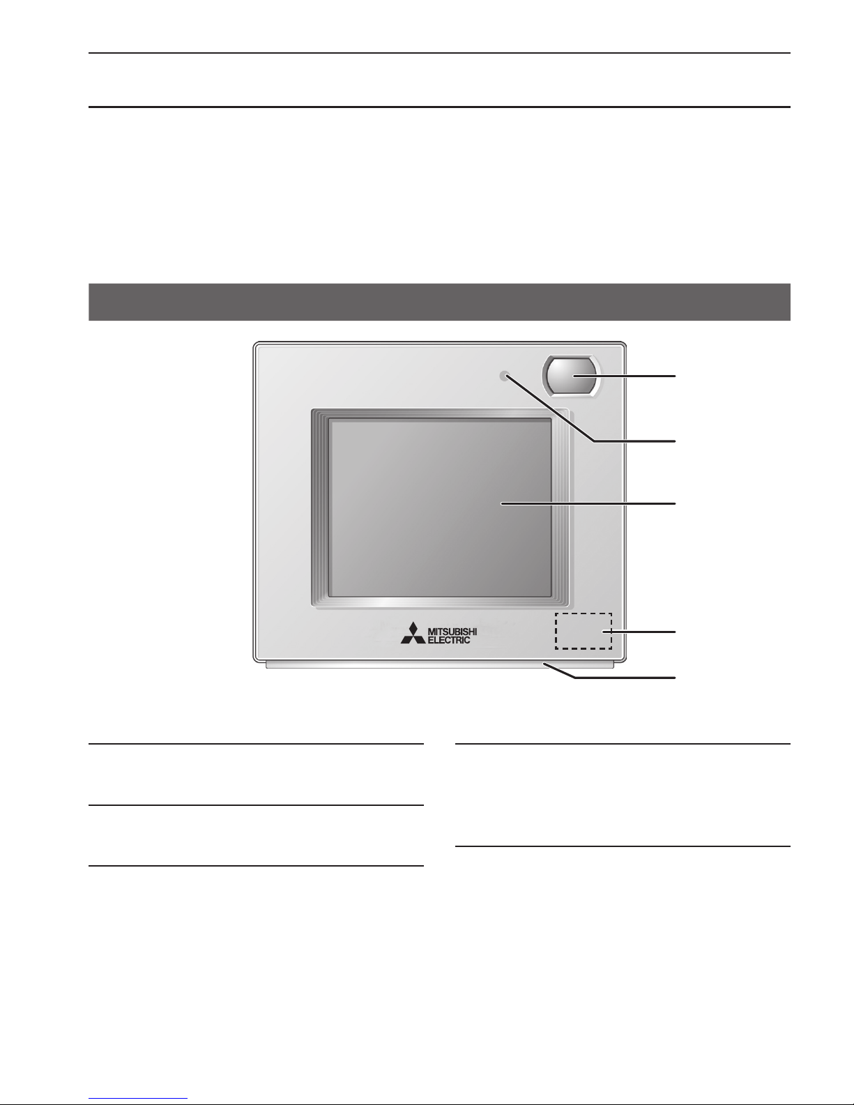
Controller interface
▌
1 Occupancy Sensor
The occupancy sensor detects vacancy for energy-save
control.
▌
2 Brightness Sensor
The brightness sensor detects the brightness of the room
for energy-save control.
▌
3 Temperature Sensor
The sensor detects the room temperature.
▌
4 LED Indicator
The LED indicator indicates the operation status in different
colors.
The LED indicator lights up during normal operation, lights
off when units are stopped, and blinks when an error
occurs.
▌
5 Touch panel & Backlit LCD
The touch panel shows the operation settings screen.
When the backlight is off, touching the panel turns the
backlight on, and it will stay lit for a predetermined period
of time.
1
2
5
3
4
Page 3
3
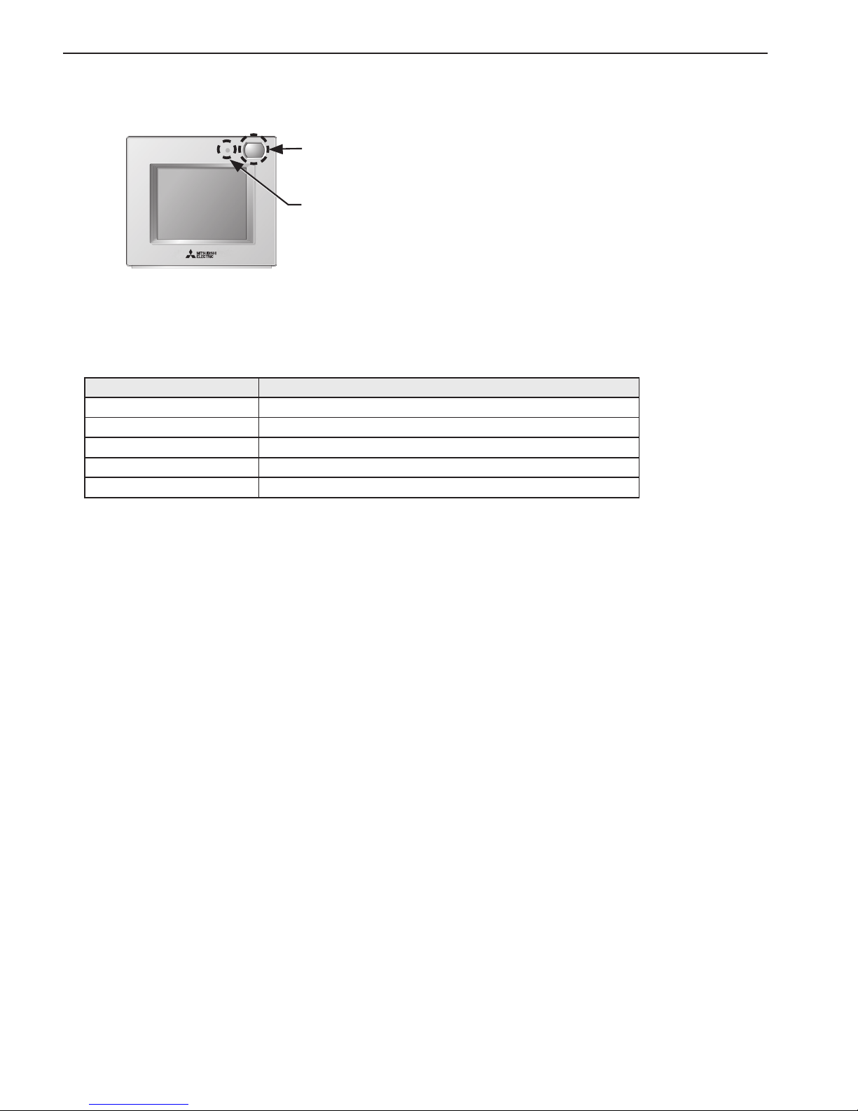
▌
Energy-save control with the use of the built-in occupancy sensor
Occupancy sensor
Brightness sensor
• Energy-save control will be performed when the occupancy sensor detects vacancy.
• When the occupancy sensor detects no human movement for a certain period of time, this will be
regarded as the vacancy.
• Only one of the following energy-save controls can be used at a time.
Energy-save control mode Control when vacancy is detected
Non-use –
ON/OFF The unit will be turned off.
Set temperature offset The set temperature will be offset.
Fan speed down The fan speed will be set to “Low.”
Zones-off The zones will be off.
• Energy-save control can be stopped according to the brightness level detected by the brightness
sensor. (Example: While the occupants are sleeping at night)
Page 4
4
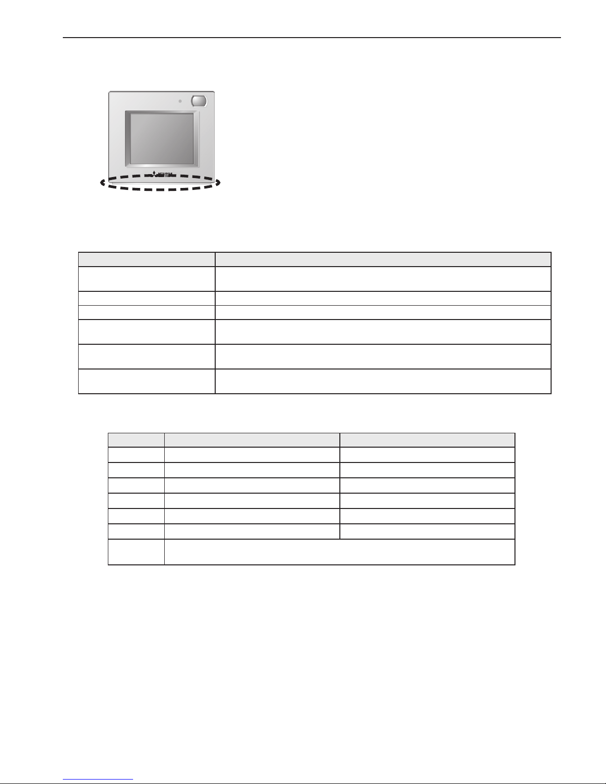
▌
LED Indicator
LED Indicator
• The LED indicator indicates the operation status by lighting and blinking with different colors and
brightness (High/Low), or by turning off.
• Indicator colors: Blue, Light blue, Purple, Red, Pink, Orange, Yellow, Green, Lime, and White
Operation status LED indicator
The unit is in operation.
Lights up in different colors according to the operation mode or the room
temperature (three different levels).
*1
The unit is stopped. Turns off.
An error is occurring. Blinks in the color it is illuminated in at the time.
Energy-save control is being
performed.
Lights up in the predetermined color.
*1
The occupancy sensor has
sensed an occupant.
Inverts the brightness (High/Low) twice.
*1
A button is touched on the
Home screen.
Inverts the brightness (High/Low).
*1
*1 The settings can be made on the LED Indicator setting screen.
Default color setting
Color Operation mode setting (default) Room temperature
Blue Cool (Auto_Cool) 0ºC–21ºC (32ºF–69ºF)
Light blue Dry Not used
Yellow Fan 21.5ºC–26ºC (70ºF–79ºF)
White Auto Not used
Red Heat (Auto_Heat) 26.5ºC–40ºC (80ºF–104ºF)
Green Night setback Not used
Lime
Energy-save control is in effect that has been performed when the occupancy
sensor detected vacancy.
* Purple, pink, and orange are not used by default.
Page 5

5
Contents
Product features ··························································· 2
Controller interface ············································································ 2
Safety precautions ························································ 6
Screen display ····························································· 8
Screen configuration ·········································································· 8
Display ···························································································· 9
Menu structure ················································································12
Icon explanations ·············································································14
Basic operations ························································· 15
Power ON/OFF ···············································································15
Operation mode, Set temperature and Fan speed settings ·······················16
Zone ON/OFF ·················································································20
Navigating through the Menu ········································ 21
Menu list ························································································21
About passwords ·············································································22
Navigating through the Menu ······························································23
Function settings ························································ 27
Date and time ··················································································27
Schedule ························································································30
Timer ·····························································································33
Night setback ··················································································38
Display format ·················································································40
Sound and contrast ··········································································41
Energy saving (Assist function) ···························································42
LED Indicator ··················································································48
Touch panel calibration ······································································51
Lock operations ···············································································52
Sensor threshold setting ····································································54
Set temperature range limit ································································59
Auto return ······················································································62
Maintenance ······························································ 65
Screen cleaning ···············································································65
Filter information ··············································································66
Troubleshooting ························································· 68
Error information ··············································································68
Specifications ···························································· 69
Controller specifications·····································································69
List of functions that can/cannot be used in combination ··························70
Page 6
6
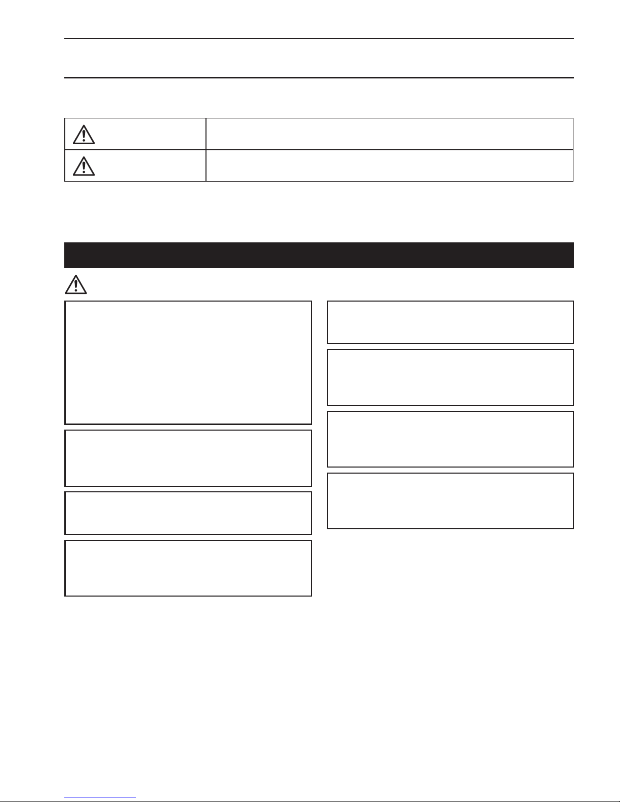
Safety precautions
• Thoroughly read the following safety precautions before using the unit.
• Observe these precautions carefully to ensure safety.
WARNING
Indicates a risk of death or serious injury.
CAUTION
Indicates a risk of serious injury or structural damage.
• After reading this manual, pass it on to the end user to retain for future reference.
• Keep this manual for future reference and refer to it as necessary. This manual should be made available
to those who repair or relocate the controller. Make sure that the manual is passed on to any future users.
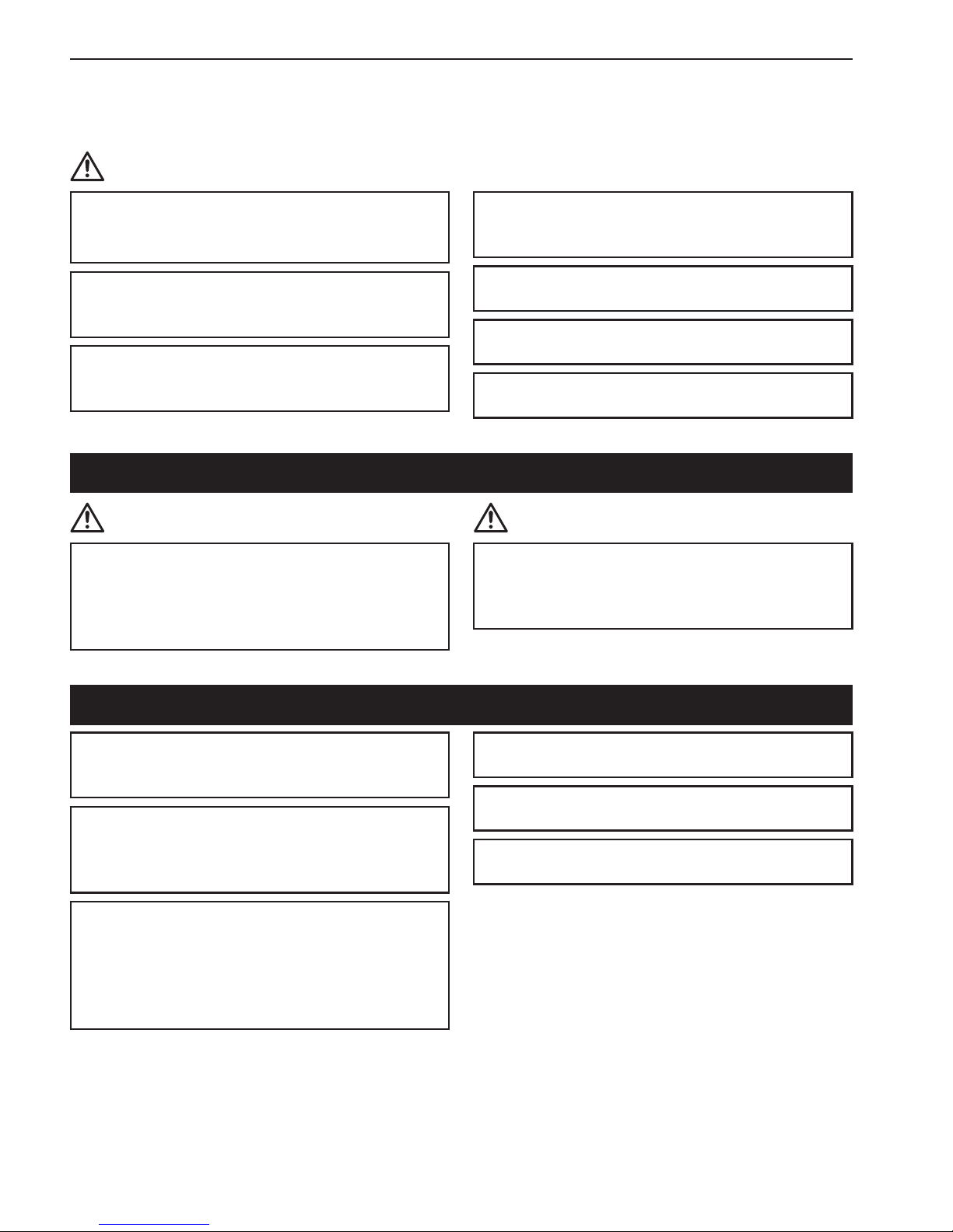
General precautions
WARNING
Do not install the unit in a place where large
amounts of oil, steam, organic solvents, or
corrosive gases, such as sulfuric gas, are present
or where acidic/alkaline solutions or sprays
are used frequently. These substances can
compromise the performance of the unit or cause
certain components of the unit to corrode, which
can result in electric shock, malfunctions, smoke,
or fire.
To reduce the risk of shorting, current leakage,
electric shock, malfunctions, smoke, or fire, do
not wash the controller with water or any other
liquid.
To reduce the risk of electric shock, malfunctions,
smoke or fire, do not operate the touch panel or
touch other electrical parts with wet hands.
When disinfecting the unit using alcohol, ventilate
the room adequately. The fumes of the alcohol
around the unit may cause a fire or explosion
when the unit is turned on.
To reduce the risk of injury or electric shock,
before spraying a chemical around the controller,
stop the operation and cover the controller.
To reduce the risk of injury or electric shock, stop
the operation and switch off the power supply
before cleaning, maintaining, or inspecting the
controller.
If any abnormality (e.g., burning smell) is noticed,
stop the operation, turn off the power switch, and
consult your dealer. Continued use of the product
may result in electric shock, malfunctions, or fire.
Properly install all required covers to keep
moisture and dust out of the controller. Dust
accumulation and water can cause electric shock,
smoke, or fire.
Page 7
7
Safety precautions
CAUTION
To reduce the risk of fire or explosion, do not
place flammable materials or use flammable
sprays around the controller.
To reduce the risk of damage to the controller, do
not directly spray insecticide or other flammable
sprays on the controller.
To reduce the risk of environmental pollution,
consult an authorized agency for proper disposal
of remote controller.
To reduce the risk of electric shock or
malfunctions, do not touch the touch panel with a
pointy or sharp object.
To reduce the risk of injury and electric shock,
avoid contact with sharp edges of certain parts.
To avoid injury from broken glass, do not apply
excessive force on the glass parts.
To reduce the risk of injury, wear protective gear
when working on the controller.
Relocation and repairs
WARNING CAUTION
The controller should be repaired or moved only
by qualified personnel. Do not disassemble or
modify the controller.
Improper installation or repair may cause injury,
electric shock, or fire.
To reduce the risk of shorting, electric shock, fire,
or malfunction, do not touch the circuit board with
tools or with your hands, and do not allow dust to
accumulate on the circuit board.
Additional precautions
To avoid damage to the controller, use
appropriate tools to install, inspect, or repair the
controller.
This controller is designed for exclusive use with
the Zone controller by Mitsubishi Electric. The
use of this controller for with other systems or for
other purposes may cause malfunctions.
To avoid discoloration, do not use benzene,
thinner, or chemical rag to clean the controller.
To clean the controller, wipe with a soft cloth
soaked in water with mild detergent, wipe off the
detergent with a wet cloth, and wipe off water with
a dry cloth.
To avoid damage to the controller, provide
protection against static electricity.
Properly dispose of the packing materials. Plastic
bags pose suffocation hazard to children.
To avoid damage to the controller, do not
overtighten the screws.
Page 8
8
Screen display
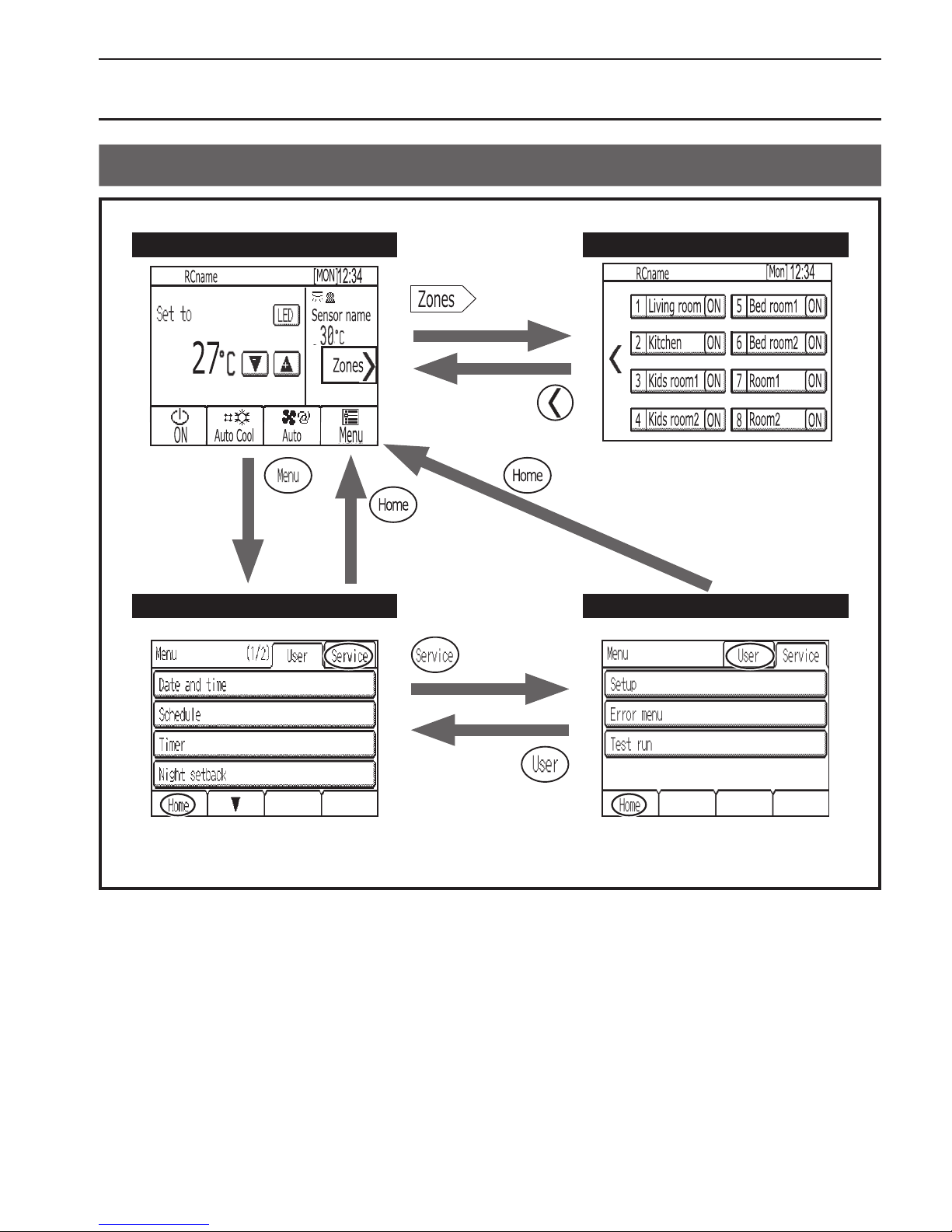
Screen configuration
Home screen Zone operation screen
Menu (User) screen Menu (Service) screen
A password is required to access the
Menu (Service) screen.
Zones will appear that are setting in
the zone setting screen.
Page 9
9
Screen display
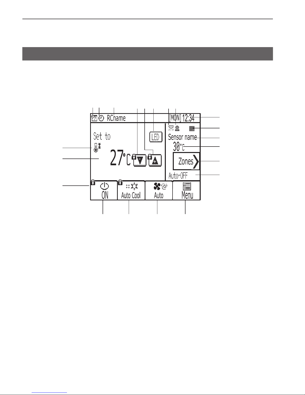
Display
▌
Home screen
* All icons are displayed for explanation.
1 2 3 4
5 5 66
93 4
7
8
)
0
2
7
8
1
!
9
Page 10
10
Screen display
▌
1 [ON/OFF] button
Touch to turn ON/OFF the indoor unit.
▌
2 [Operation mode] button
Touch to change the operation mode.
▌
3
[Fan] button
Touch to change the fan speed.
▌
4 [Menu] button
Touch to bring up the Menu screen.
▌
5 LED Indicator ON/OFF button
Touch to turn ON/OFF the LED indicator.
▌
6
Touch to decrease the set temperature.
▌
7
Touch to increase the set temperature.
▌
8
Touch to go to the zone operation screen.
▌
9 Remote controller name
Remote controller name appears here.
▌
0 Room temperature for control
Current room temperature for control appears here.
▌
1 Set temperature
The set temperature appears here.
The display varies with the selected operation mode.
▌
2 Day and time
Current day and time appear here.
▌
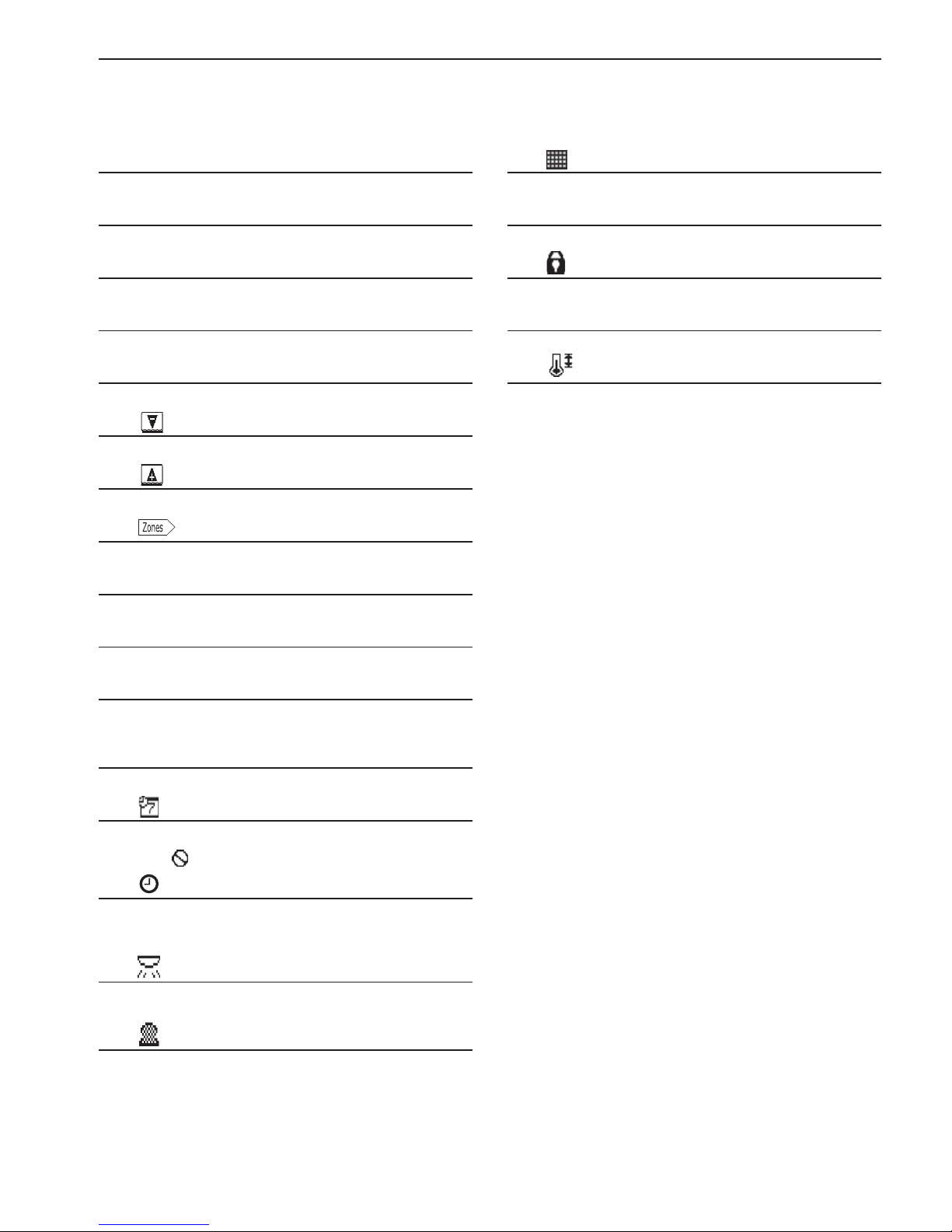
3
Appears when the scheduled operation is being performed.
The icon
appears when the timer operation is prohibited.
▌
4
Appears when the ON/OFF timer is activated or when the
Zone ON/OFF timer is activated or when the Night setback
function is enabled.
▌
5
Appears when the brightness sensor detects light brighter
than a predetermined level.
▌
6
Appears when the occupancy sensor senses an occupant.
▌
7
Appears when the filter needs maintenance.
▌
8 Sensor name for control
Current sensor name for control appears heare.
▌
9
Appears when the operation is locked.
▌
) Auto-OFF display
Appears when the Auto-OFF timer is activated.
▌
!
Appears when the set temperature range is restricted.
Page 11
11
Screen display
▌
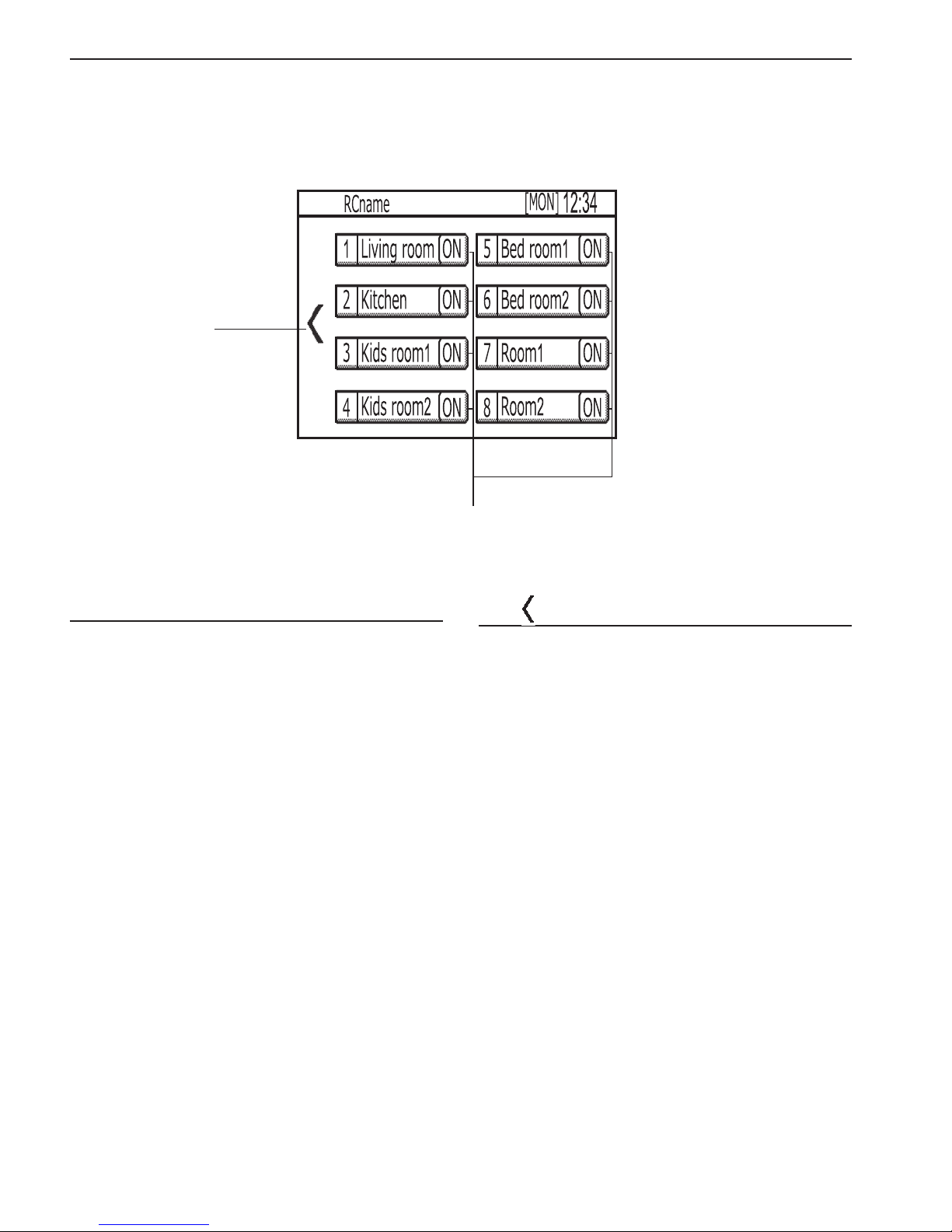
Zone operation screen
#
@
▌
@ [Zones ON/OFF] button
Touch to turn ON/OFF the zones.
▌
#
Touch to return to the Home screen.
Page 12
12
Screen display
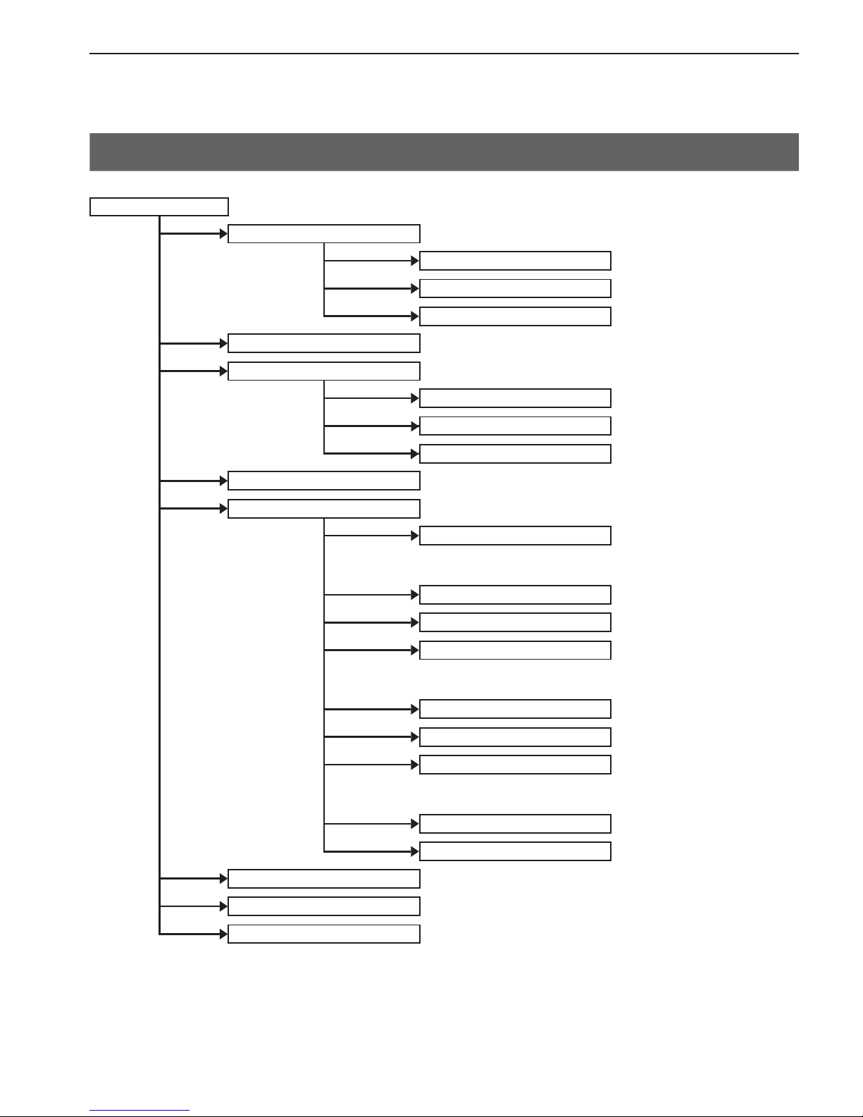
Menu structure
Menu (User)
Date and time
··· Page 27
Enter date and time
··· Page 27
Date and time format
··· Page 28
Daylight saving time
··· Page 29
Schedule
··· Page 30
Timer
··· Page 33
Unit ON/OFF timer
··· Page 33
Unit Auto-OFF timer
··· Page 35
Zone ON/OFF timer
··· Page 36
Night setback
··· Page 38
Settings
Display format
··· Page 40
— Room temperature display
— Backlight timeout
Sound and contrast
··· Page 41
Energy saving
··· Page 42
LED Indicator
··· Page 48
— LED Indicator setting
— With Brightness sensor
Touch panel calibration
··· Page 51
Lock operations
··· Page 52
Sensor threshold setting
··· Page 54
— Occupancy sensor
— Brightness sensor
Set temp. range limit
··· Page 59
Auto return
··· Page 62
Screen cleaning
··· Page 65
Filter information
··· Page 66
Error information
··· Page 68
Page 13
13
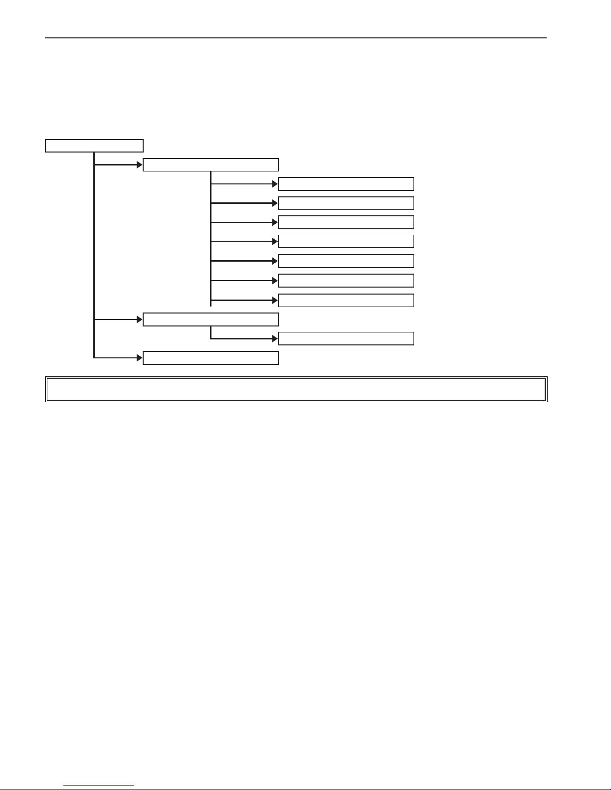
Screen display
Menu (Service)
··· Refer to the Installation Manual for details.
Setup
IC Function settings
Zones setting
Name setting
Cool/Heat display
Telephone number
LED color adjustment
Reset RC
Error menu
Self check
Test run
Not all functions are available on all models of indoor units.
Page 14
14
Screen display
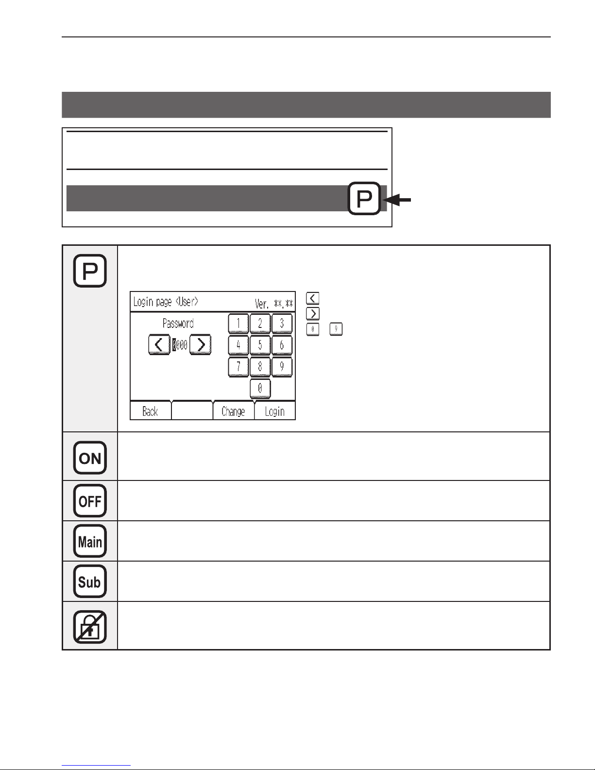
Icon explanations
Function settings
Timer
The table below
summarizes the square
icons used in this manual.
The user password must be entered on the [Login page] to change settings.
There is no settings that can skip this process.
: Touch to move the cursor left.
: Touch to move the cursor right.
- : Touch to input the number.
* Changes cannot be made unless the correct
password is entered.
Indicates settings that can be changed only while the unit is in operation.
Indicates setting that can be changes only while the unit is not in operation
Indicates setting that can operate only Main remote controller
Indicates setting that can operate only Sub remote controller
Indicates functions that are not available when the buttons are locked.
Page 15
15
Basic operations
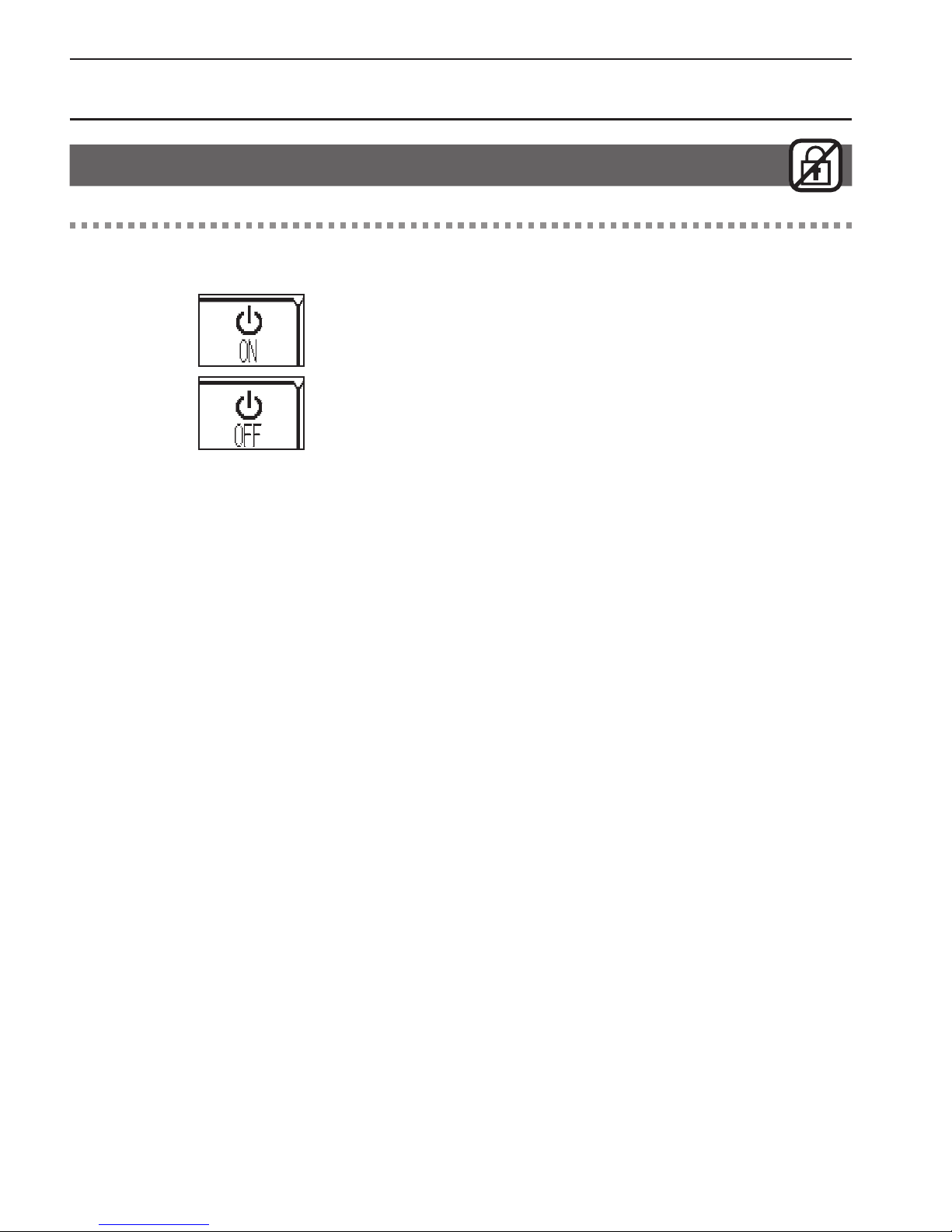
Power ON/OFF
Button operation
ON/OFF
Touch the [ON/OFF] button to turn on or off the
indoor unit.
* The LED indicator will light up when the indoor unit is
turned on.
* The LED indicator display depends on the settings for the
function settings.
* The unit will operate with the previously-set operation
mode, set temperature, and fan speed.
Page 16
16
Basic operations
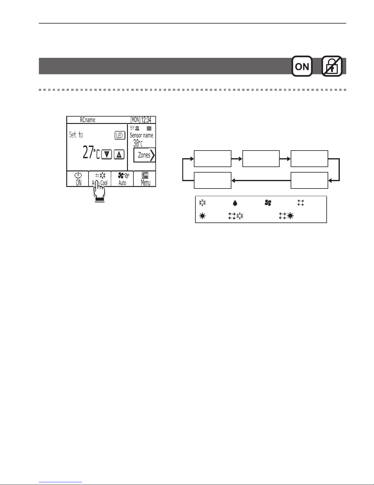
Operation mode, Set temperature and Fan speed settings
Button operation
Operation mode
Touch the [Operation mode] button to go through
the operation modes in the following order.
Select the desired operation mode.
Cool
Dry
*1
Fan
Heat
*1
Auto
*1
Cool Dry Fan Auto
Heat Auto_Cool Auto_Heat
*1 Operation modes that are not available for the
connected indoor unit will not appear on the display.
* LED indicator color changes according to the operation
mode and the settings for the function settings.
Page 17
17
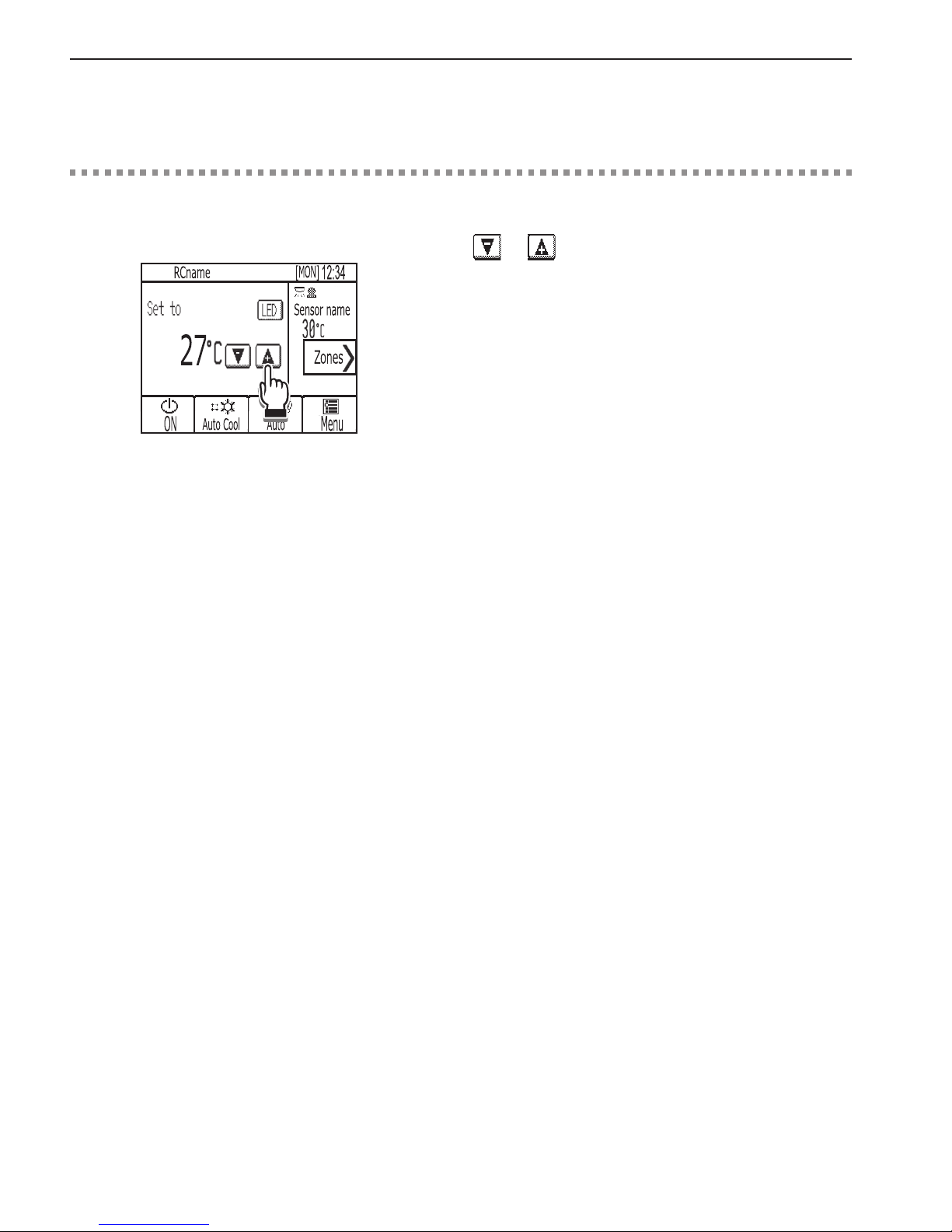
Basic operations
Button operation
Set temperature
Cool, Heat, or Auto mode
Touch or to decrease or increase the set
temperature.
• Refer to the table on page 18 for the settable
temperature range for different operation modes.
• Set temperature cannot be set for the Fan mode.
Page 18
18
Basic operations
▌
Set temperature range
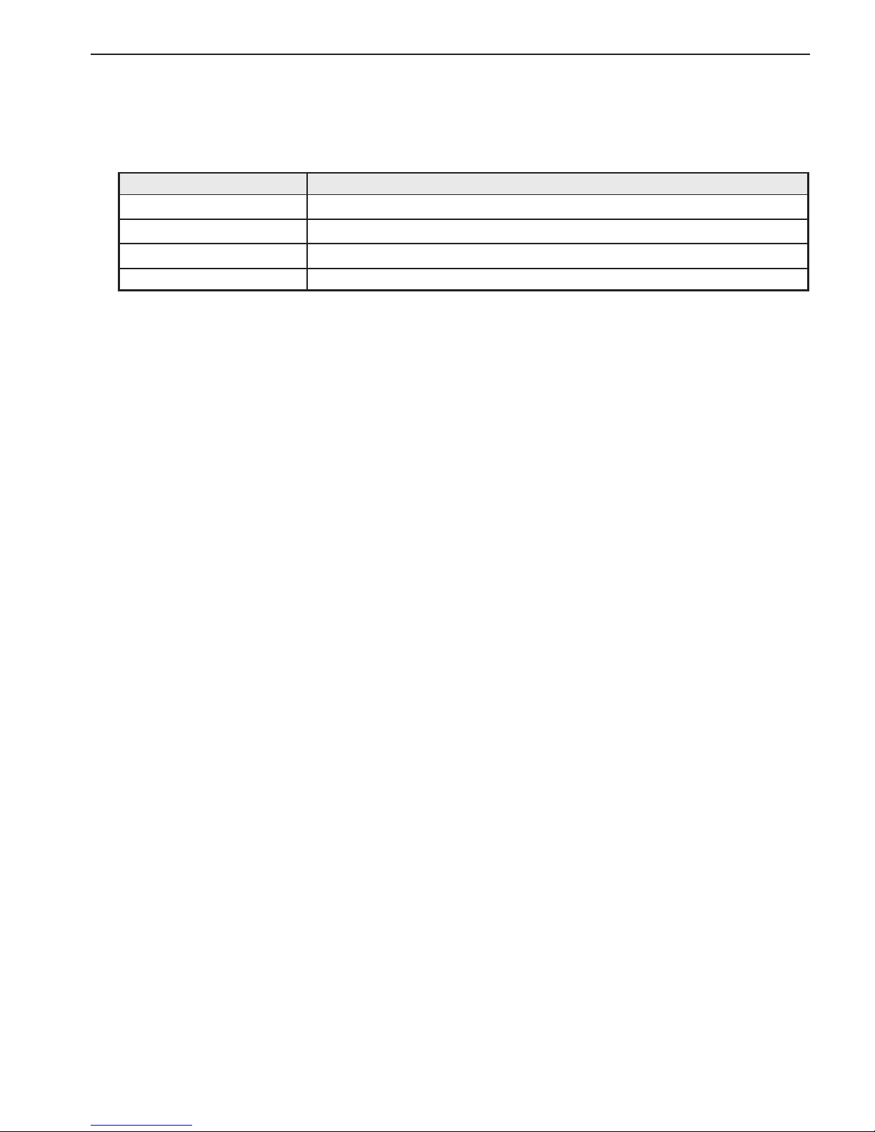
Operation mode Set temperature range
Cool/Dry
19–30ºC (67–87ºF)
*1*2
Heat
17–28ºC (63–83ºF)
*1*2
Auto
19–28ºC (67–83ºF)
*1*2
Fan Not settable
*1 The settable temperature ranges vary, depending on the indoor unit model.
*2 Restrictions for the set temperature range will apply, if any. If the setting value is outside of the range, a message
“Temp. range locked” will appear.
Page 19
19
Basic operations
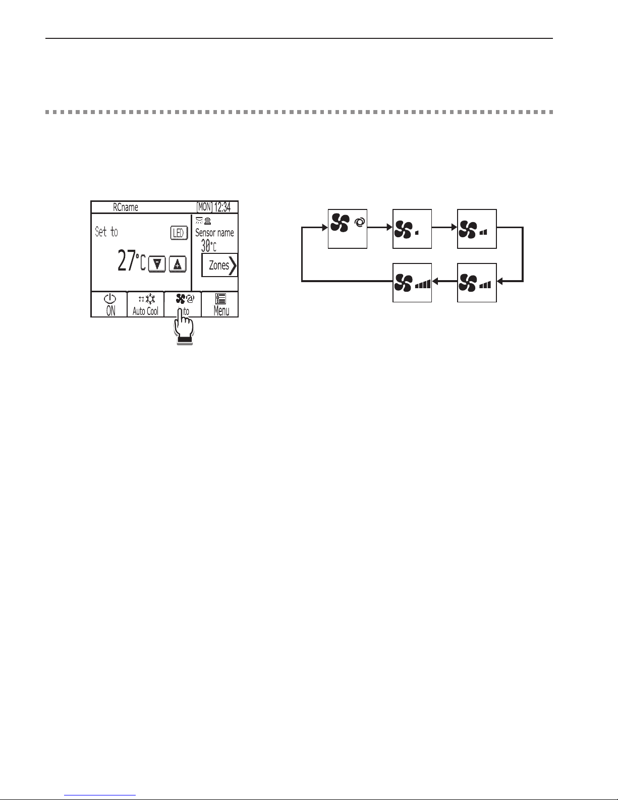
Button operation
Fan speed
Touch the [Fan speed] button to go through the fan
speeds in the following order.
Select the desired setting.
Auto
• The number of available fan speeds depends on the
indoor unit model.
<Note>
The actual fan speed will differ from the fan speed
displayed on the LCD when one of the following conditions
is met.
• While “Standby” or “Defrost” is displayed
• When the room temperature is higher than the set
temperature during the heating mode
• Immediately after the heating operation (during stand by
for switching the operation mode)
• During the Dry mode
Page 20
20
Basic operations
Zone ON/OFF
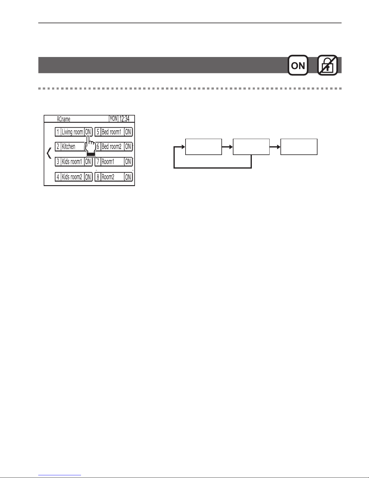
Button operation
Zone ON/OFF
Touch the [ON/OFF] button to turn on or off the each
zones.
OFF ON SPL*1
*1 When all zones are fully closed, a zone which is set to
as spill zone will open automatically.
Page 21
21
Navigating through the Menu
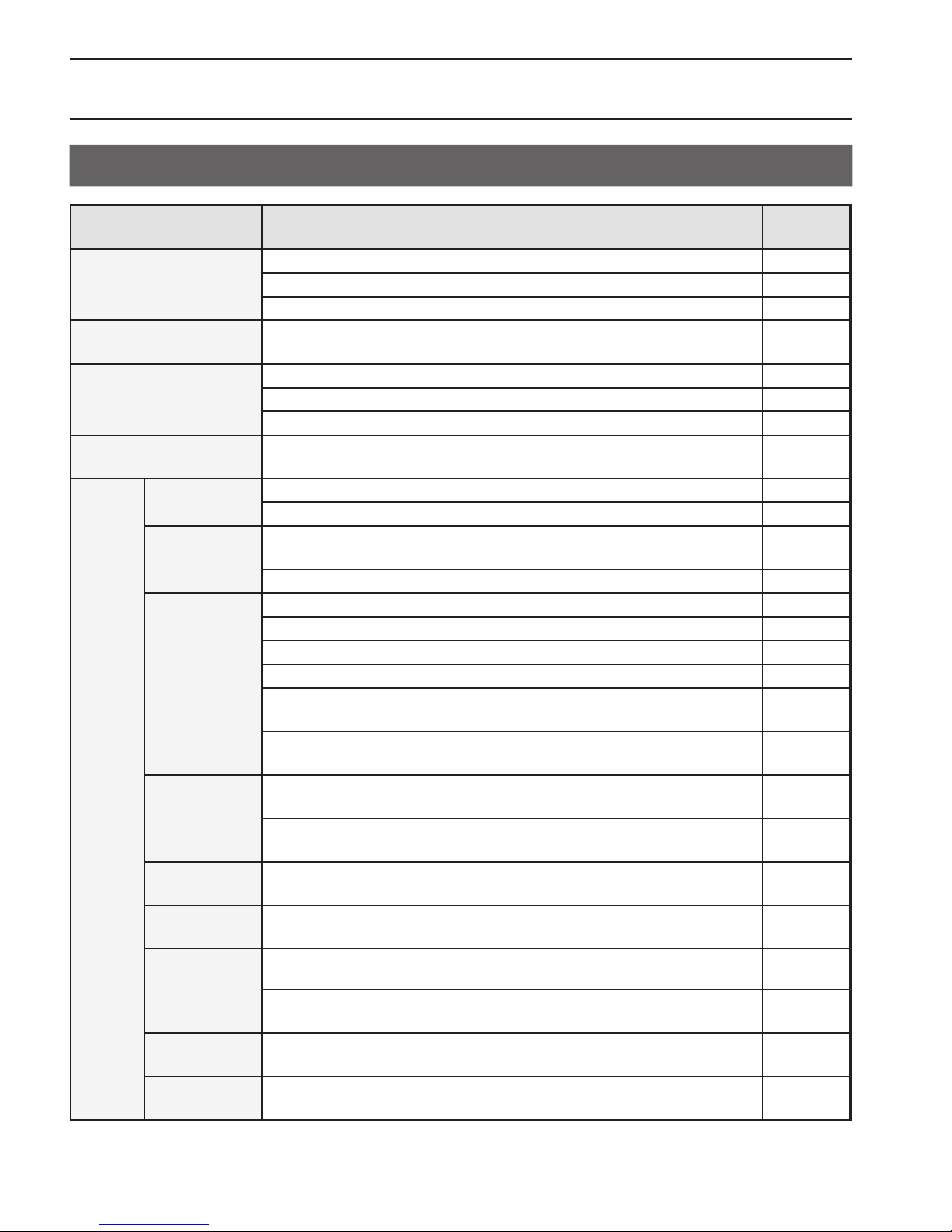
Menu list
Menu items Setting items and details
Reference
page
Date and time
Sets the current date and time. 27
Selects the date and time format. 28
Sets the daylight saving time. 29
Schedule
Schedules the operation ON/OFF times, operation modes, set
temperatures and zones ON/OFF for a week.
30
Timer
Sets the Unit ON/OFF timer. 33
Sets the Unit Auto-OFF timer. 35
Sets the Zone ON/OFF timer. 36
Night setback
Sets the temperature range and start/stop times for the Night
setback function.
38
Settings
Display format
Show/Hide room temperature setting. 40
Backlight timeout setting. 40
Sound and
contrast
Sets the volume of the buzzer that sounds when the screen is
touched.
41
Sets the screen contrast. 41
Energy saving
Turns off the unit for the energy-save control. 42
Offsets the set temperature for the energy-save control. 42
Sets the fan speed to “Low” for the energy-save control. 42
Turns off the zones for the energy - save control. 42
Specifies the days and the time periods when the energy-save
control will be deactivated.
45
Sets the brightness sensor condition to deactivate the energy-save
control.
45
LED Indicator
Sets the operation mode display setting.
Sets the room temperature display setting.
48
Selects the use or non-use of brightness sensor to switch LED
indicator brightness.
48
Touch panel
calibration
Sets the calibration settings for the touch panel. 51
Lock
operations
Locks the Unit ON/OFF, Operation mode, Set temperature, and
Zones ON/OFF.
52
Sensor
threshold
setting
Sets the detection sensitivity level for the occupancy sensor. 54
Sets the brightness/darkness detection thresholds for the
brightness sensor.
57
Set temp.
range limit
Limits the settable temperature ranges for the Cool, Heat, and
Auto modes.
59
Auto return
Operates the unit at the specified temperature after the specified
period of time.
62
Page 22
22
Navigating through the Menu
Menu items Setting items and details
Reference
page
Screen cleaning
Temporarily makes the touch panel unresponsive to touch to allow
for cleaning.
65
Filter information Displays and resets the filter signs on the indoor unit. 66
Error information Displays the error status when an error occurs. 68
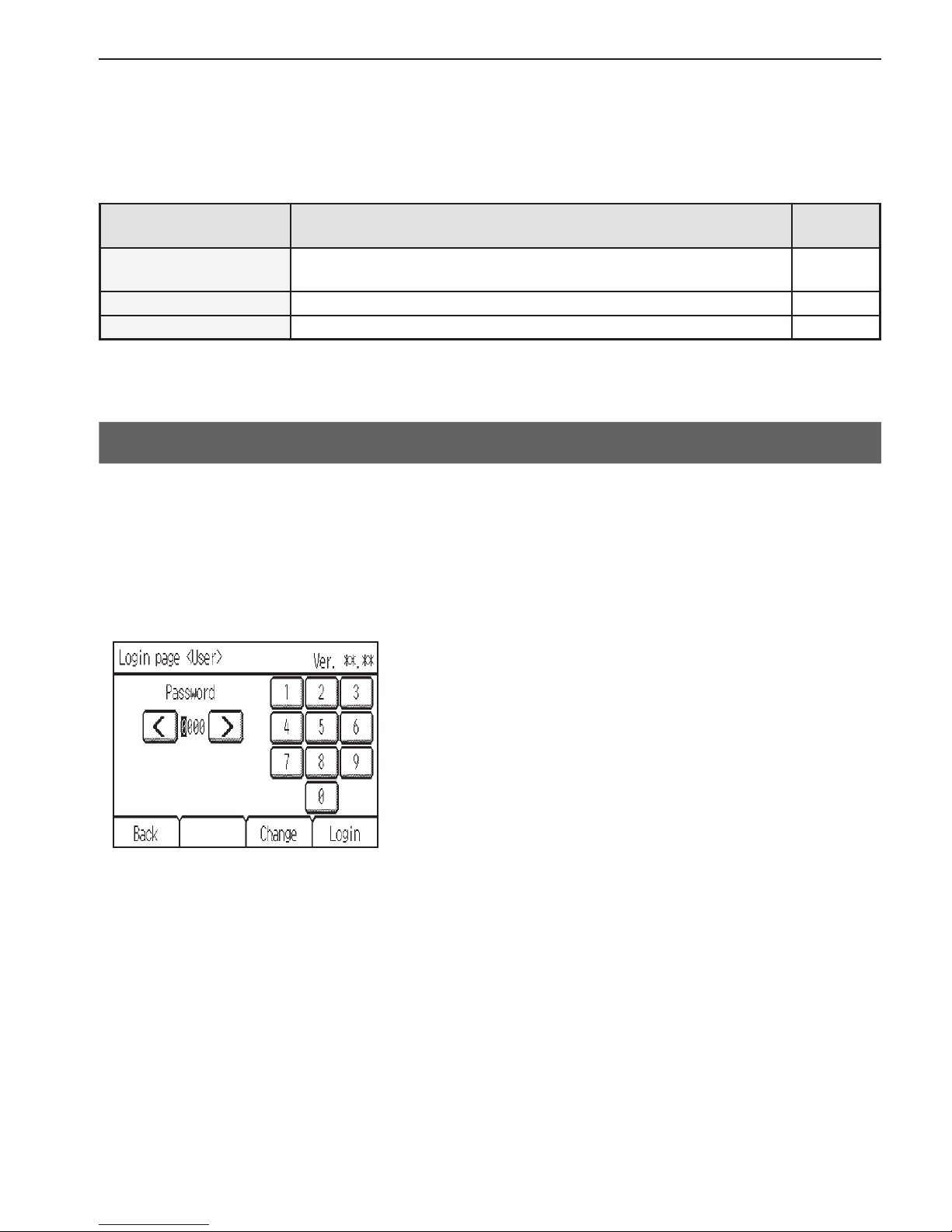
About passwords
A password is required to access certain windows.
Two types of passwords are used as follows.
• Password that is used on the Menu (User)
• Password that is used on the Menu (Service)
Example enter-password screen
* Refer to section 2 “Service Menu” in Chapter 2 “Initial Setting” in the Installation Manual for details about
passwords.
Page 23

23
Navigating through the Menu
Navigating through the Menu
Button operation
Accessing the Menu
Touch the [Menu] button.
The Menu screen will appear.
Page 24

24
Navigating through the Menu
Button operation
Navigating through the pages
Touch or to switch between the pages.
To access the Menu (Service) screen, touch the
[Service] tab.
A maintenance access password will be required to
access the Menu (Service) screen.
Page 25

25
Navigating through the Menu
Button operation
Item selection
Touch the desired item on the Menu screen.
When an attempt is made to access a passwordprotected screen, a [Login page] will appear.
Enter a user password (default: 0000).
The settings screen for the selected item will appear.
Navigating through the screens
• To return to the Menu screen: [Menu] button
• To return to the previous screen: [Back] button
Page 26

26
Navigating through the Menu
Button operation
Exiting the Menu screen
Touch the [Home] button to exit the Menu screen and
return to the Home screen.
If no buttons are touched for 10 minutes, the screen will automatically return to the Home
screen. Any settings that have not been saved will be lost.
Page 27

27
Function settings
Function settings
Date and time
▌
Enter date and time
Button operation
1
Select [Date and time] from the Menu.
Then, touch [Enter date and time] in the list.
Date and time setting is required before making
the following settings.
• Schedule
• Unit ON/OFF timer
• Zone ON/OFF timer
• Night setback
• Energy saving
• Daylight saving time
2
Touch or to set the current date, month,
year, and time.
Touch [Done] to save the settings.
Navigating through the screens
• To return to the Menu screen: [Menu] button
• To return to the previous screen: [Back] button
Page 28

28
▌
Date and time format
Button operation
1
Select [Date and time] from the Menu.
Then, touch [Date and time format] in the list.
2
Touch the buttons to select date and time display
formats.
Touch [Done] to save the settings.
Navigating through the screens
• To return to the Menu screen: [Menu] button
• To return to the previous screen: [Back] button
Page 29

29
Function settings
▌
Daylight saving time
Button operation
1
Select [Date and time] from the Menu.
Then, touch [Daylight saving time] in the list.
2
The default setting is “Disabled.”
To activate the daylight saving time, touch the
[Disabled] button to change it to [Enabled].
Set the following items with the
buttons.
• Date/Month <Start>
• Start time
• Forward to
* Set the time when the clock is to be set forward to at
the Start time above.
• Date/Month <End> (2nd page)
• End time (2nd page)
• Backward to (2nd page)
* Set the time when the clock is to be set backward to
at the End time above.
Touch [Done] to save the settings.
Navigating through the screens
• To return to the Menu screen: [Menu] button
• To return to the previous screen: [Back] button
Page 30

30
Function settings
Schedule
Operation Unit ON/OFF times, operation modes, set temperatures and zones ON/OFF for a
week can be scheduled. Up to eight operation patterns can be scheduled for each day.
<Setting the schedules>
1
Select [Schedule] from the Menu.
The Schedule function will not work in the
following cases: when the Unit ON/OFF timer
is enabled, the Zone ON/OFF timer is enabled,
during an error, during test run, when the clock is
not set.
2
The default setting is “Disabled.”
To activate the Schedule function, touch the
[Disabled] button to change it to [Enabled].
Touch [Done] to access the settings screen.
3
The current settings will appear.
Touch the day of the week button to see the
schedule settings for the day.
Up to eight operation patterns can be scheduled
for each day. Touch to see patterns 4 through 8.
Touch the row of the pattern you want to edit.
Page 31

31
Function settings
4
The current settings for the selected day will
appear.
5
Set the following items.
• Time
* The time is settable in 5-minute increments.
* Touch and hold
or to rapidly advance the
numbers.
• ON/OFF
• Mode
• Temperature
* The settable operation modes and temperature
ranges vary, depending on the indoor unit model.
To continue setting schedules for other time
periods, touch
to access the settings screen.
When done making the settings, touch [Zones].
Zones schedule setting screen will appear.
6
Set the Zones ON/OFF.
To continue setting schedules for other time
periods, touch
to access the setting screen.
When done making the setting, touch [Done].
A confirmation screen will appear.
Touch [OK] to save the settings.
Navigating through the screens
• To return to the Menu screen: [Menu] button
• To return to the previous screen: [Back] button
Page 32

32
Function settings
<Copying a schedule>
1
To copy the schedule settings of a day to the
schedule settings for another day of the week,
touch [Copy].
2
Touch the day whose schedule settings are to
be copied and the day(s) to which the copied
schedule settings are to be pasted.
When done making the settings, touch [Done].
A confirmation screen will appear.
Touch [OK] to save the settings.
Navigating through the screens
• To return to the Menu screen: [Menu] button
• To return to the previous screen: [Back] button
will appear on the Home screen when the
schedule setting for the current day exists.
The icon will not appear while the Unit ON/OFF
timer or Zone ON/OFF timer is enabled. In these
cases, scheduled events will not be executed.
Page 33

33
Function settings
Timer
▌
Unit ON/OFF timer
Unit ON/OFF timer allows the user to set a timer to turn on or off the indoor unit at the
specified times.
Button operation
1
Select [Timer] from the Menu.
Then, touch [Unit ON/OFF timer] in the list.
The Unit ON/OFF timer will not work in the
following cases: when Unit ON/OFF timer is
disabled, during an error, during test run, when the
clock is not set.
2
To activate the Unit ON/OFF timer, touch the
[Disabled] button to change it to [Enabled].
Specify the [ON]-time and [OFF]-time with the
buttons.
* The time is settable in 5-minute increments.
* Touch and hold
or to rapidly advance the
numbers.
To set the ON/OFF timer to repeat daily, set the
[Repeat] setting to [Enabled].
Touch [Done] to save the settings.
Navigating through the screens
• To return to the Menu screen: [Menu] button
• To return to the previous screen: [Back] button
Page 34

34
Function settings
will appear on the Home screen when the ON/
OFF timer is enabled.
Page 35

35
Function settings
▌
Unit Auto-OFF timer
Unit Auto-OFF timer allows the user to set a timer to turn off the indoor unit after the
specified time has elapsed.
Button operation
1
Select [Timer] from the Menu.
Then, touch [Unit Auto-OFF timer] in the list.
The Unit Auto-OFF timer will not work in the
following cases: when Unit Auto-OFF timer is
disabled, during an error, during test run.
2
To activate the Auto-OFF timer, touch the
[Disabled] button to change it to [Enabled].
Specify the [Stop in]-time with the buttons.
* Specify the time to elapse before the indoor unit is
automatically turned off. The settable range is 0.5 to
24 hours in 0.5 hours increments.
* Touch and hold
or to rapidly advance the
numbers.
Touch [Done] to save the settings.
Navigating through the screens
• To return to the Menu screen: [Menu] button
• To return to the previous screen: [Back] button
“Auto-OFF” will appear on the Home screen when
the Unit Auto-OFF timer is enabled.
Page 36

36
Function settings
▌
Zone ON/OFF timer
Zone ON/OFF timer allows the user to set a timer to turn on or off the zone at the specified
times.
Button operation
1
Select [Timer] from the Menu.
Then, touch [Zone ON/OFF timer] in the list.
The Zone ON/OFF timer will not work in the
following cases: when Zone ON/OFF timer is
disabled, during an error, during test run, when the
clock is not set.
2
To activate the Zone ON/OFF timer, touch the [No]
button to change it to [Yes].
Page 37

37
Function settings
3
To activate the Zone ON/OFF timer, touch the
[Disabled] button to change it to [Enabled].
Specify the [ON]-time and [OFF]-time with the
buttons.
* The time is settable in 5-minute increments.
* Touch and hold
or to rapidly advance the
numbers.
To set the ON/OFF timer to repeat daily, set the
[Repeat] setting to [Enabled].
Touch [Done] to save the settings.
Navigating through the screens
• To return to the Menu screen: [Menu] button
• To return to the previous screen: [Back] button
will appear on the Home screen when the Zone
ON/OFF timer is enabled.
Page 38

38
Function settings
Night setback
The Night setback function starts heating operation when a given group is stopped and
the room temperature drops below the specified lower limit temperature. Also, this function
starts cooling operation when a given group is stopped and the room temperature rises
above the specified upper limit temperature.
* If the room temperature is measured by the return air temperature sensor on the air conditioning unit,
the measured value may not be an accurate representation of the temperature in the room, especially
when the air conditioning unit is stopped and the room air is stagnant. When this is the case, use
optional sensor or remote controller sensor to measure the room temperature.
Button operation
1
Select [Night setback] from the Menu.
The Night setback function will not work in the
following cases: when the unit is in operation,
when the Night setback function is disabled,
during an error, during test run, when the clock is
not set.
The Night setback function will be cancelled when
the Unit ON/OFF operation, operation mode
setting, or set temperature setting is made from
the remote controller while the Night setback
function is executed.
2
The default setting is “Disabled.”
To activate the Night setback function, touch the
[Disabled] button to change it to [Enabled].
To continue making detailed settings, touch
to
access the settings screen.
Page 39

39
Function settings
3
The current settings will appear.
Set the following items.
• Temperature range
* Set the upper limit temperature for cooling operation
and the lower limit temperature for heating operation.
* The difference between the lower and upper limit
temperatures must be 4ºC (8ºF) or more.
* The settable temperature range varies depending on
the connected indoor unit model.
• Start/Stop times
* The time is settable in 5-minute increments.
* Touch and hold
or to rapidly advance the
numbers.
Touch to access the previous screen.
Touch [Done] to save the settings.
Navigating through the screens
• To return to the Menu screen: [Menu] button
• To return to the previous screen: [Back] button
Page 40

40
Function settings
Display format
▌
Room temperature for control display
▌
Backlight timeout
Button operation
1
Touch [Settings] from the Menu.
Then, touch [Display format] in the list.
2
Room temperature for control display
Touch the button to select the desired room
temperature for control display option to be used
on the Home screen.
• Show: Room temperature for control appears on
the Home screen.
• Hide: Room temperature for controldoes not
appear on the Home screen.
Backlight timeout
Touch the button to select the desired timeout of
the backlight from 5, 10, 20, 30, and 60 seconds.
Touch [Done] to save the settings.
Navigating through the screens
• To return to the Menu screen: [Menu] button
• To return to the previous screen: [Back] button
Page 41

41
Function settings
Sound and contrast
▌
Sound level
▌
Contrast
Button operation
1
Touch [Settings] from the Menu.
Then, touch [Sound and contrast] in the list.
2
Sound level
Set the volume of the buzzer that sounds when the
screen is touched.
• Level 0–3 (Level 0: No sound)
Contrast
Set the display contrast between -10 and +10.
The greater the value, the higher the contrast.
Touch [Done] to save the settings.
Navigating through the screens
• To return to the Menu screen: [Menu] button
• To return to the previous screen: [Back] button
Page 42

42
Function settings
Energy saving (Assist function)
The energy-save control assist function can be set to activate when vacancy is detected
while the air conditioning units are operated. (The default setting for this function is set to
deactivate.)
▌
Selecting an energy-save control mode
Button operation
1
Touch [Settings] from the Menu.
Then, touch [Energy saving] in the list.
Page 43

43
Function settings
2
Touch the [Mode] button to select one of the
following energy-save control modes that reduces
energy-consumption during vacancy.
The default setting is “Non-use.”
• Non-use: Deactivates the energy-save control
assist function.
• Set temperature offset
*1
: Offsets the set
temperature.
• Fan speed down
*2
: Sets the fan speed to “Low.”
• ON/OFF: Turns off the unit.
• Zone control: Turns off the zones.
*1 When the units are operated in the Fan mode, the set
temperature will not be offset.
*2 If the connected indoor unit does not support the
fan speed adjustment function, this item will not be
displayed.
When the occupancy sensor detects occupancy
during the energy-save control, the original
operating status will be restored.
However, when the operating status is changed
by other controllers or by the scheduled or timercontrolled events, the current operating status will
be retained even if the occupancy sensor detects
occupancy.
<Note>
• To use the energy-save control assist function in a
system with both main and sub remote controllers,
activate the function only on the remote controller
whose coverage area is the largest.
Page 44

44
Function settings
3
Set the following items with the buttons.
• Offset value (Effective only when “Set
temperature offset” mode is selected)
* Set the temperature value to be offset by from the set
temperature during vacancy. The settable value range
is between 1ºC (2ºF) and 4ºC (8ºF).
• Auto-away time (Effective when any mode is
selected)
* When no human movement is detected for the period
of the time specified here, the energy-save control will
be performed. However, if the user perform a manual
operation, the timer will be restarted.The settable time
range is between 0:00 and 24:00.
• Detection level (Effective when any mode is
selected)
* Adjust the detection sensitivity level according to the
surrounding environment. (Recommended setting
for ordinary use: Level 0) The greater the value, the
higher the sensitivity. The settable levels are -2, -1, 0,
1, and 2.
* A higher detection level can lead to false detection
because the sensor tends to detect more noise.
When the [Mode] button is Zone control, [Next]
button will appear.
As zones setting, the energy-save control zones
can be set to active.
As option settings, the energy-save control assist
function can be set to deactivate during vacancy
at the specified time periods on the specified days
or when the brightness sensor detects “Light” or
“Dark.” (See page 45 for details.)
When done making the settings and if no settings
need to be made for the option settings, touch
[Done] to save the settings.
To make option settings, touch [Option].
Page 45

45
Function settings
▌
Invalid item setting (option settings)
Button operation
1
The energy-save control assist function can be
set to deactivate during vacancy at the specified
time periods on the specified days or when the
brightness sensor detects “Light” or “Dark.”
To specify time periods and days, touch [Day and
time] from the list. (See step 2 below.)
To set the detection conditions for the brightness
sensor, touch [With Brightness sensor] from the
list. (See step 3 below.)
These two different types of settings can be made
in combination. The energy-save control assist
function will be deactivated when one of the
conditions for the above items is met.
Page 46

46
Function settings
2
Day and time
Specify the days and the time periods when
the energy-save control assist function will be
deactivated.
The settings of a day can be copied to the settings
for another day of the week.
The setting details are the same as those for the
schedule settings. Refer to page 30 for details.
* To deactivate the function for an entire day, set the
setting to “0:00→0:00.”
3
With Brightness sensor
To use the brightness sensor for the energy-save
control, touch the [Disabled] button to change it to
[Enabled].
Touch the [Occupancy sensor invalid condition]
button to select [Light] or [Dark].
• Light: When the brightness sensor detects “Light”
during vacancy, the energy-save control
assist function will be deactivated.
• Dark: When the brightness sensor detects “Dark”
during vacancy, the energy-save control
assist function will be deactivated.
Touch [Done] to save the settings.
Navigating through the screens
• To return to the Menu screen: [Menu] button
• To return to the previous screen: [Back] button
Page 47

47
Function settings
Example of the energy-save control assist function settings
Setting item Setting example
Invalid item setting
(option settings)
Day and time
1 7:00 → 17:00
With Brightness sensor
2 Light
Energy-save control mode
3 Set temperature offset
(Offset value: 2ºC)
Auto-away time
4 0:10 (10 minutes)
7:00 17:00
Normal control Normal control
Because the settings for the items under [Invalid item setting] are
made, the energy-save control will not be performed at these times even
when the occupancy sensor detects vacancy.
Period during which energy-save control can not be performed even
when vacancy is detected
Period during which energy-save control can be performed when vacancy
is detected
Energy-
save
control
Energy-
save
control
4 Auto-away
time
(10 min.)
Light
Occupied
21ºC
1 Time
(1 + 2)
3 Set temp.
(Heat)
Dark
Vacant
19ºC
Auto-away time
count restarts.
Auto-away time
count restarts.
2
Page 48

48
Function settings
LED Indicator
Button operation
1
Touch [Settings] from the Menu.
Then, touch [LED Indicator] in the list.
2
Touch [LED Indicator setting] in the list.
Page 49

49
Function settings
3
The default setting for [Basic display mode] is
“Mode.”
Touch the button to select the Basic display mode
from “Mode,” “Room temp.,” or “Non-use.”
Setting items common to “Mode” and “Room
temp.”
• Brightness
* Select “High” or “Low.”
* This setting is effective only when the “With
Brightness Sensor” setting (explained on the next
page) is disabled.
• Color during energy saving (2nd page)
* Select the desired color to be used during energy-
save control.
• Occupancy detection indicator (2nd page)
* Select “Enabled” or “Disabled.”
When “Enabled” is selected, the LED indicator blinks
once every 30 seconds when the occupancy sensor
detects occupancy.
Setting item specific to “Mode”
• Mode color (3rd and 4th pages)
* Select the desired LED color for each operation
mode.
Setting item specific to “Room temp.”
• Room temp. for control range and LED color (3rd
page)
* Set the desired temperature ranges and the LED
colors for low, medium, and high temperature range
groups.
Touch [Done] to save the settings.
Navigating through the screens
• To return to the Menu screen: [Menu] button
• To return to the previous screen: [Back] button
Page 50

50
Function settings
4
To select the brightness level of the LED indicator
to be used when the brightness sensor detects
“Light” or “Dark,” touch the [With Brightness
sensor] in the list.
5
To use the brightness sensor for switching
the brightness of the LED indicator, touch the
[Disabled] button to change it to [Enabled].
Set the following items.
• Detection: Light
* Select the brightness level of the LED indicator to be
used when the brightness sensor detects “Light.”
Select “Brighten,” “Darken,” or “OFF”
• Detection: Dark
* Select the brightness level of the LED indicator to be
used when the brightness sensor detects “Dark.”
Select “Brighten,” “Darken,” or “OFF”
Touch [Done] to save the settings.
Navigating through the screens
• To return to the Menu screen: [Menu] button
• To return to the previous screen: [Back] button
Page 51

51
Function settings
Touch panel calibration
Button operation
1
Touch [Settings] from the Menu.
Then, touch [Touch panel calibration] in the list.
A confirmation screen will appear.
Touch [OK].
2
Touch the black dots in the order they appear,
starting from the top left corner.
After all nine squares are touched, the screen will
return to the previous screen.
• If each square is not touched within one minute after the last square is touched, calibration
will be canceled and the screen will return to the previous screen.
• To calibrate the screen properly, use a pointy, but not sharp object to touch the black dots.
* Sharp objects may scratch the touch panel.
Page 52

52
Function settings
Lock operations
Button operation
1
Touch [Settings] from the Menu.
Then, touch [Lock operations] in the list.
2
To lock the following operation items, touch the
[Unlocked] button to change it to [Locked].
• ON/OFF
• Operation mode
• Set temperature
• Zones
Touch [Done] to save the settings.
Navigating through the screens
• To return to the Menu screen: [Menu] button
• To return to the previous screen: [Back] button
Page 53

53
Function settings
Button operation
will appear on the Home screen when the
unit ON/OFF operation, operation mode, set
temperature are locked.
will appear on the Zone operation screen when
the One ON/OFF operation is locked.
Page 54

54
Function settings
Sensor threshold setting
▌
Occupancy sensor
Button operation
1
Touch [Settings] from the Menu.
Then, touch [Sensor threshold setting] in the list.
2
To set the detection sensitivity level of the
occupancy sensor, touch [Occupancy sensor] in
the list.
Page 55

55
Function settings
3
Set the detection sensitivity level with the
buttons.
• Level: -2, -1, 0 (default), 1, 2
* The detection level setting made here will also be
reflected on the detection level setting on the “Energy
saving” screen.
The larger the value, the more sensitive the sensor
will be to light.
Use the default conditions under normal conditions.
If the sensor is oversensitive or undersensitive,
adjust the detection sensitivity level.
Use the following tests to adjust the detection
sensitivity to the appropriate level: A vacancy test
(Test 1) and an occupancy test (Test 2).
A higher detection sensitivity level can lead to false
detection because the sensor tends to detect more
noise.
Touch [Done] to save the settings.
Navigating through the screens
• To return to the Menu screen: [Menu] button
• To return to the previous screen: [Back] button
Page 56

56
Function settings
Performing sensor detection sensitivity tests
Test 1: Vacancy test Test 2: Occupancy test
To start Test 1, touch [Test 1].
Ten seconds later, the vacancy detection
test will automatically begin.
This test will test for the presence of
noise that leads to false detection.
Leave the room within 10 seconds after
touching the button, and leave the room
unoccupied for 1 minute until the test is
completed.
When the test is complete, the result
will be displayed in color on the LED
indicator.
• Blue: Normal (The sensor correctly
detected vacancy without being
interfered with by noise.)
• Red: Error (The sensor falsely detected
occupancy due to noise.)
If the sensor failed to correctly detect
vacancy, lower the detection sensitivity
level and try again.
To start Test 2, touch [Test 2].
When movements are detected, the LED
indicator will light up in blue.
Walk away from the remote controller,
and walk around in areas where you
want the sensor to detect motions to see
if it will respond correctly.
If the sensor does not respond, raise the
detection sensitivity level and try again.
The sensor detection area is as follows: 110° to either side, 10 meters (32 feet).
Some conditions will render the sensor susceptible to false detection.
Refer to “How To Install” in chapter 1 in the Installation Manual.
Page 57

57
Function settings
▌
Brightness sensor
Button operation
1
Touch [Settings] from the Menu.
Then, touch [Sensor threshold setting] in the list.
2
To set the threshold value of the brightness sensor,
touch [Brightness sensor] in the list.
3
The lux values to be used to determine the "Dark"
state and "Light" state can be set.
These statuses are used as parameters for
energy-save control and LED indicator control.
Set the lux values to an appropriate values suitable
for a given environment.
Try changing the brightness in a given space (e.g.,
by drawing curtains) while adjusting the lux levels.
Set the values and touch [Done].
Navigating through the screens
• To return to the Menu screen: [Menu] button
• To return to the previous screen: [Back] button
Page 58

58
Function settings
Performing a test
When [Test] is touched, the current lux level in a given space will appear next to
“Monitor” on the screen.
The LED indicator will indicate the brightness status of a given space in colors.
Red
Light
Green
Dark
Blue
Page 59

59
Function settings
Set temperature range limit
Button operation
1
Touch [Settings] from the Menu.
Then, touch [Set temp. range limit] in the list.
Page 60

60
Function settings
2
The default setting is “Disabled.”
To limit the settable temperature ranges for the
Auto, Cool (Dry), and Heat modes, touch the
[Disabled] button to change it to [Enabled].
Set the upper and lower limit temperatures for
the following operation modes in the table below
with the
buttons. (The temperatures will
decrease or increase by 1ºC or 1ºF increments.)
• If the connected indoor unit does not feature the Auto
mode, the items related to the Auto mode will not be
displayed.
Settable upper and lower limit temperatures
Operation mode Lower limit Upper limit
Auto
19°C–28°C
(67°F–83°F)
28°C–19°C
(83°F–67°F)
Cool/Dry
19°C–30°C
(67°F–87°F)
30°C–19°C
(87°F–67°F)
Heat
17°C–28°C
(63°F–83°F)
28°C–17°C
(83°F–63°F)
* The settable operation modes and temperature ranges
vary, depending on the indoor unit model.
* The cooling and heating temperature ranges can be set
under the following conditions.
- The difference between the cooling and heating
upper limit temperatures is equal or greater than the
minimum temperature difference that varies with the
indoor unit model.
- The difference between the cooling and heating
lower limit temperatures is equal or greater than the
minimum temperature difference that varies with the
indoor unit model.
Page 61

61
Function settings
When done making the settings, touch [Done] to
save the settings.
Navigating through the screens
• To return to the Menu screen: [Menu] button
• To return to the previous screen: [Back] button
will appear on the Home screen when the
temperature range is limited.
Page 62

62
Function settings
Auto return
The Auto-return function allows the user to operate the unit at the specified temperature
after the specified period of time.
Button operation
1
Touch [Settings] from the Menu.
Then, touch [Auto return] in the list.
Page 63

63
Function settings
2
The default setting is “Disabled.”
To activate the Auto-return function, touch the
[Disabled] button to change it to [Enabled].
Set the following items with the
buttons.
The temperatures will decrease or increase by 1ºC
or 1ºF increments.
• Cool
* Specify the time to elapse before the set temperature
automatically changes to the set temperature
specified below during cooling operation. The
settable time range is 10 to 120 minutes in 10-minute
increments.
* Specify the set temperature to be used after
the period of time specified above. The settable
temperature range is 19ºC to 30ºC (67ºF to 87ºF)
(depending on the indoor unit model).
* “Cool” includes the “Dry” and “Auto_Cool” modes.
• Heat
* Specify the time to elapse before the set temperature
automatically changes to the set temperature
specified below during heating operation. The
settable time range is 10 to 120 minutes in 10-minute
increments.
* Specify the set temperature to be used after
the period of time specified above. The settable
temperature range is 17ºC to 28ºC (63ºF to 83ºF)
(depending on the indoor unit model).
* “Heat” includes the “Auto_Heat” modes.
When done making the settings, touch [Done] to
save the settings.
Navigating through the screens
• To return to the Menu screen: [Menu] button
• To return to the previous screen: [Back] button
The Auto-return function settings will not be effective when the set temperature range is restricted.
Page 64

64
Function settings
<Sample screens when the Auto-return function is enabled>
Example: Lower the set temperature to 24ºC (75ºF). Sixty minutes later, the set
temperature will automatically change to 28ºC (83ºF).
60 minutes
later
The set temperature is
manually changed from 28ºC
(83ºF) to 24ºC (75ºF).
Sixty minutes later, the set
temperature automatically
changes to 28ºC (83ºF).
Page 65

65
Maintenance
Screen cleaning
Button operation
1
Touch [Screen cleaning] from the Menu.
A confirmation screen will appear.
Touch [OK].
2
Clean the touch panel within 30 seconds. The
touch panel is deactivated for 30 seconds and then
returns to the Menu screen.
* The buzzer will sound while the touch panel is being
touched.
Wipe with a soft dry cloth, a cloth soaked in water with mild detergent, or a cloth dampened
with ethanol. Do not use acidic, alkaline, or organic solvents.
Page 66

66
Maintenance
Filter information
will appear on the Home screen when it is time
to clean the filters.
Wash, clean, or replace the filters when this sign
appears.
Refer to the indoor unit Instructions Manual for
how to clean the filters.
Button operation
1
Touch [Filter information] from the Menu.
2
Touch [Reset] to reset the filter sign.
A confirmation screen will appear.
Touch [OK].
Page 67

67
Maintenance
3
A message indicating that the filter information has
been reset will appear.
Navigating through the screens
• To return to the Menu screen: [Menu] button
• To return to the previous screen: [Back] button
will appear when the filter on one of the units is due for cleaning.
When the filter sign is reset, the cumulative operation time of all units will be reset.
is scheduled to appear after a certain duration of operation, based on the premise that the indoor
units are installed in a space with ordinary air quality. Depending on the air quality, the filter may require
more frequent cleaning.
The cumulative time at which filter needs cleaning depends on the model.
Page 68

68
Troubleshooting
Error information
When an error occurs, the [Error information] screen will appear.
Check the error status, stop the operation, and consult your dealer.
Button operation
1
Error code, error unit, and address will appear.
Dealer’s phone number will appear if the
information has been registered in the settings
screen under the Menu (Service).
* The LED indicator will blink at 1-second intervals while
the error is occurring.
Touch [Reset] to reset the error that is occurring.
A confirmation screen will appear.
Touch [OK].
2
A message indicating that the error information has
been reset will appear.
Navigating through the screens
• To return to the Menu screen: [Menu] button
• To return to the previous screen: [Back] button
Page 69

69
Specifications
Controller specifications
Specifications
Power Source
17–32 VDC
*1
(for connection to M-NET only)
Receives power from zone control
interface via the M-NET transmission
cable.
Operating
conditions
Temperature
Operating temperature range 0ºC – +40ºC (+32ºF – +104ºF)
Storage temperature range -20ºC – +60ºC (-4ºF – +140ºF)
Humidity 20%–90% RH (Non-condensing)
Weight
0.3 kg (11/16 lbs)
External dimensions
(W x H x D)
140 x 120 (123) x 25 (28.8) mm
5-17/32 x 4-3/4 (4-27/32) x 1 (1-5/32) in
* The numbers in the parenthesis indicate the dimensions including the protruding
parts.
*1 Not for use with a generic DC power supply device.
Page 70

70
Specifications
List of functions that can/cannot be used in combination
Schedule
Unit or Zone
ON/OFF timer
Unit Auto-OFF timer
Auto return
Set temp. range limit
Lock operations
Night setback
Energy saving
(Assist function)
Schedule
1 4
Unit or Zone
ON/OFF timer
1 2
Unit Auto-OFF timer
3
Auto return
2 6 1
Set temp. range limit
2 5
Lock operations
Night setback
4 2 3 6 5 7
Energy saving
(Assist function)
1 7
: The functions can be used in combination. : Restricted : The functions cannot be used in combination.
1 : The “Schedule” setting is not effective because “ON/OFF timer” has the higher priority.
2 : The “Auto return” function cannot be used because the “Set temp. range limit” setting has the
higher priority.
1 : The “Auto return” function will not be executed when the units are operated in the “Set
temperature offset” mode.
2 : The “Night setback” function will not be executed when the unit has been turned on by “Unit ON/
OFF timer.”
When Zone ON/OFF timer is set, both of the functions will remain effective.
3 : The “Unit Auto-OFF timer” function will not be executed while the “Night setback” function is
executed.
4 : The “Night setback” function will not be executed when the unit has been turned on by “Schedule”
settings.
5 : The “Set temp. range limit” settings will not be effective while the “Night setback” function is
executed.
6 : The “Auto return” function will not be executed while the “Night setback” function is executed.
7 : The “Energy saving” function will not be executed while the “Night setback” function is executed.
Page 71

71
Note:
This equipment has been tested and found to comply with the limits for a Class B digital device, pursuant
to Part 15 of the FCC Rules. These limits are designed to provide reasonable protection against harmful
interference in a residential installation. This equipment generates, uses and can radiate radio frequency
energy and, if not installed and used in accordance with the instructions, may cause harmful interference to
radio communications.
However, there is no guarantee that interference will not occur in a particular installation.
If this equipment does cause harmful interference to radio or television reception, which can be determined by
turning the equipment off and on, the user is encouraged to try to correct the interference by one or more of the
following measures:
- Reorient or relocate the receiving antenna.
- Increase the separation between the equipment and receiver.
- Connect the equipment into an outlet on a circuit different from that to which the receiver is connected.
- Consult the dealer or an experienced radio/TV technician for help.
Page 72

HEAD OFFICE: TOKYO BLDG. , 2-7-3, MARUNOUCHI, CHIYODA-KU, TOKYO 100-8310, JAPAN
Authorized representative in EU: MITSUBISHI ELECTRIC EUROPE B.V.
HARMAN HOUSE, 1 GEORGE STREET, UXBRIDGE, MIDDLESEX UB8 1QQ, U.K.
BH79D481H01 Printed in Japan
 Loading...