

Page 1

DP-8800Plus/DP-8600/
DP-9900/DP-9900Plus/DP-9600
Digital Ultrasonic Diagnostic
Imaging System
Installation Manual
Page 2

© 2007 Shenzhen Mindray Bio-medical Electronics Co., Ltd. All rights Reserved.
Intellectual Property Statement
SHENZHEN MINDRAY BIO-MEDICAL ELECTRONICS CO., LTD. (hereinafter called
Mindray) owns the intellectual property rights to this Mindray product and this manual. This
manual may refer to information protected by copyrights or patents and does not convey any
license under the patent rights of Mindray, nor the rights of others. Mindray does not assume
any liability arising out of any infringements of patents or other rights of third parties.
Mindray intends to maintain the contents of this manual as confidential information.
Disclosure of the information in this manual in any manner whatsoever without the written
permission of Mindray is strictly forbidden.
Release, amendment, reproduction, distribution, rent, adaptation and translation of this
manual in any manner whatsoever without the written permission of Mindray is strictly
forbidden.
, , , , are the registered trademarks or
trademarks owned by Mindray in China and other countries. All other trademarks that
appear in this manual are used only for editorial purposes without the intention of improperly
using them. They are the property of their respective owners.
Responsibility on the Manufacturer Party
Contents of this manual are subject to changes without prior notice.
All information contained in this manual is believed to be correct. Mindray shall not be liable
for errors contained herein nor for incidental or consequential damages in connection with
the furnishing, performance, or use of this manual.
Mindray is responsible for safety, reliability and performance of this product only in the
condition that:
•
all installation operations, expansions, changes, modifications and repairs of this product
are conducted by Mindray authorized personnel;
•
the electrical installation of the relevant room complies with the applicable national and
local requirements;
•
the product is used in accordance with the instructions for use.
I-1
Page 3

WARNING:
It is important for the hospital or organization that employs this
equipment to carry out a reasonable service/maintenance plan.
Neglect of this may result in machine breakdown or injury of
human health.
Warranty
THIS WARRANTY IS EXCLUSIVE AND IS IN LIEU OF ALL OTHER WARRANTIES,
EXPRESSED OR IMPLIED, INCLUDING WARRANTIES OF MERCHANTABILITY OR
FITNESS FOR ANY PARTICULAR PURPOSE.
Exemptions
Mindray's obligation or liability under this warranty does not include any transportation or
other charges or liability for direct, indirect or consequential damages or delay resulting from
the improper use or application of the product or the use of parts or accessories not
approved by Mindray or repairs by people other than Mindray authorized personnel.
This warranty shall not extend to:
any Mindray product which has been subjected to misuse, negligence or accident;
any Mindray product from which Mindray's original serial number tag or product
identification markings have been altered or removed;
any product of any other manufacturer.
Return Policy
Return Procedure
In the event that it becomes necessary to return this product or part of this product to
Mindray, the following procedure should be followed:
1. Obtain return authorization: Contact the Mindray Service Department and obtain a
Customer Service Authorization (Mindray) number. The Mindray number must appear
on the outside of the shipping container. Returned shipments will not be accepted if the
Mindray number is not clearly visible. Please provide the model number, serial number,
and a brief description of the reason for return.
2. Freight policy: The customer is responsible for freight charges when this product is
shipped to Mindray for service (this includes customs charges).
I-2
Page 4

3. Return address: Please send the part(s) or equipment to the address offered by
Customer Service department
Company Contact
Manufacturer: Shenzhen Mindray Bio-Medical Electronics Co., Ltd.
Address: Mindray Building, Keji 12th Road South, Hi-tech Industrial
Park, Nanshan, ShenzhenShenZhen518057, P.R.China,518057
Tel: +86 755 26582479 26582888
Fax: +86 755 26582934 26582500
I-3
Page 5
Safety Precautions
1. Meaning of Signal Words
In this operation manual, the signal words
CAUTION
signal words and their meanings are defined as follows. Please understand their meanings
clearly before reading this manual.
Signal word Meaning
DANGER
WARNING
CAUTION
NOTE
and NOTE are used regarding safety and other important instructions. The
Indicates an imminently hazardous situation which, if not avoided,
will result in death or serious injury.
Indicates a potentially hazardous situation which, if not avoided,
could result in death or serious injury.
Indicates a potentially hazardous situation which, if not avoided,
may result in minor or moderate injury.
Indicates a potentially hazardous situation which, if not avoided, may
result in property damage.
DANGER, WARNING
2. Meaning of Safety Symbols
,
Symbol Description
Type-BF applied part
All ultrasound transducers can be connected to this system are
Type-BF applied parts.
"Attention" indicates the points requiring attention. Be sure to read the
operation manual concerning these points before using the equipment.
S-1
Page 6
3. Safety Precautions
Please observe the following precautions to ensure patient and operator safety when using
this system.
DANGER:
WARNING:
1. Do connect the plugs of this equipment and its peripherals to the
Do not use flammable gasses such as anesthetic gas, oxygen or
hydrogen, or flammable liquids such as ethanol, near this product,
because there is danger of explosion.
wall receptacles meeting the ratings indicated on the rating
nameplate. Using an adapter or multi-functional receptacle may
affect the system’s grounding performance and thus cause leakage
current exceeding safety requirement.
The video printer must be connected to the designated auxiliary
power outlet, and the equipment-provided cable for the printer must
be used to connect the printer. Otherwise, other cables may cause
electric shock.
CAUTION:
1.Precautions concerning clinical examination techniques
(1) This system must be used only by medical personnel fully
trained in clinical examination techniques.
(2) This operation manual does not describe clinical
examination techniques. Selection of the proper clinical
examination technique must be based on specialized
training and clinical experience.
NOTE: 1. Do not use the machine in the vicinity of strong electromagnetic field (such
as the transformer), which may affect the performance of the monitor.
S-2
Page 7

CONTENTS
1 Introduction...........................................................................................1-1
1.1 Overview................................................................................................................. 1-1
1.2 Front View .............................................................................................................. 1-1
1.3 Left View................................................................................................................. 1-2
1.4 Rear View............................................................................................................... 1-3
2 Installation Requirements ....................................................................2-1
2.1 Power Requirements.............................................................................................. 2-1
2.2 Installation Conditions ............................................................................................ 2-1
2.3 Installation Space ................................................................................................... 2-1
2.4 Environmental Conditions ...................................................................................... 2-1
2.5 Ground Requirement.............................................................................................. 2-2
2.6 Storage and Transport Requirements .................................................................... 2-2
2.7 Symbol Description ................................................................................................ 2-2
3 Unpacking Checks................................................................................3-1
3.1 Packing List of the DP-8800 Plus/DP-8600 Systems ............................................ 3-1
3.2 Peripherals of the DP-8800 Plus/DP-8600 systems .............................................. 3-1
3.3 Packing List of the DP-9900 Plus/DP-9600/DP-9900 Systems ............................. 3-1
3.4 Peripherals of the DP-9900 Plus/DP-9600/DP-9900 Systems .............................. 3-2
4 Tools and Time Required .....................................................................4-1
4.1 Tools Requirement ................................................................................................. 4-1
4.2 Time and Manpower Requirement......................................................................... 4-1
5 Installation of DP-8800plus/DP-8600 Systems....................................5-1
5.1 Installation of Push Handle..................................................................................... 5-1
5.2 Installation of Monitor ............................................................................................. 5-1
5.3 Installation of Transducer Cable Hook ................................................................... 5-3
5.4 Installation of Transducer ....................................................................................... 5-4
5.5 Installation of Peripherals ....................................................................................... 5-5
6 Installation of DP-9900PLUS/DP-9900/DP-9600 Systems..................6-1
6.1 Installation of Push Handle..................................................................................... 6-1
6.2 Installation of Monitor ............................................................................................. 6-1
6.3 Installation of Transducer Cable Hook ................................................................... 6-3
6.4 Installation of Transducer ....................................................................................... 6-3
C-1
Page 8

6.5 Installation of Peripherals ....................................................................................... 6-4
7 Installation Quality Checks..................................................................7-1
Items Checked after the Completion of Installation .......................................................... 7-1
C-2
Page 9
1
1.1
The DP-8800Plus/DP-8600 and DP-9900/DP-9900Plus/DP-9600 diagnostic ultrasound
systems are intended for clinical ultrasound examinations.
1.2
Overview
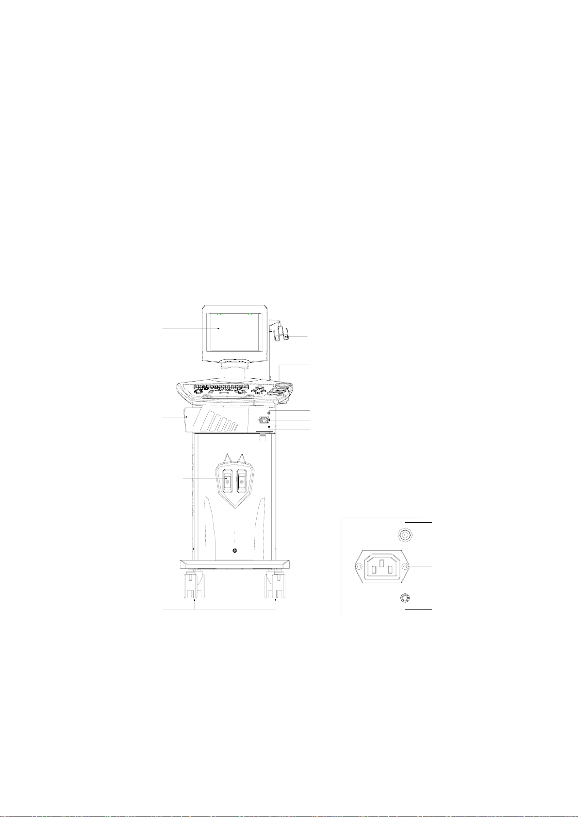
Front View
Introduction
<1>
<4>
<2>
<3>
<5>
<6>
<7>
<8>
<9>
<10>
1. Monitor 2. Transducer cable hook 3. Transducer holder 4. Printer compartment 5.Video
outlet 6. Auxiliary power outlet 7. Port for video printer 8. Transducer socket 9. Footswitch
port 10. Caster
Front view for the DP-8800plus/DP-8600 systems
<5>
<7>
<6
>
1-1
Page 10
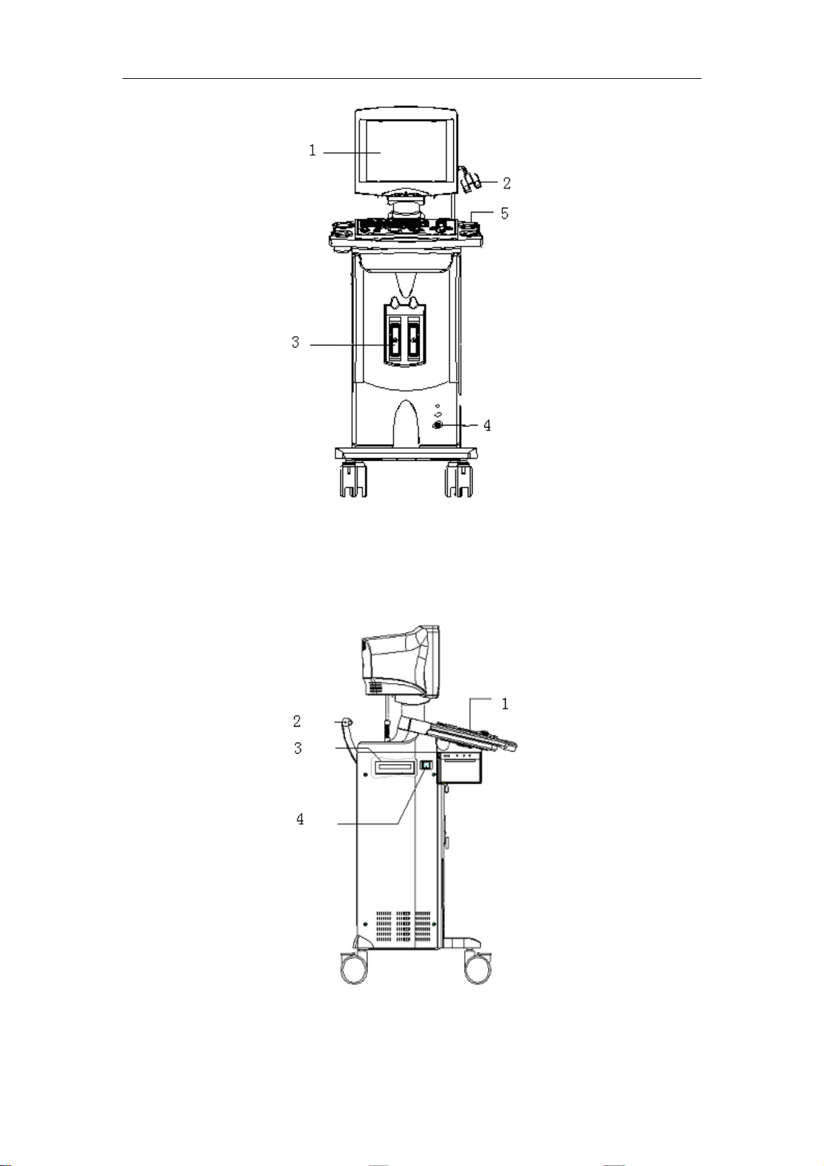
Introduction
1. Monitor 2. Transducer cable hook 3. Transducer socket 4. Footswitch port
Front view for the DP-9900plus/DP-9600/DP-9900 systems
1.3
Left View
1. Control panel 2. Push handle 3. CD driver 4. Power switch
Left view for the DP-8800plus/DP-8600 systems
1-2
Page 11

Introduction
1. Control panel 2. Top plate 3. Push handle 4. CD writer 5. Power switch
Left view for the DP-9900plus/DP-9600/DP-9900 systems
1.4
Rear View
Figure for IO ports
Note: 1. VIDEO 2. Parallel port 3. SVIDEO 4. RS232 5. VGA 6. USB 7. NET 8.
Power inlet 9. Ground terminal
Rear view for the DP-8800plus/DP-8600 systems
1-3
Page 12

Introduction
Figure for IO ports
Note: 1. VGA 2. SIVIDEO 3. VIDEO 4. VIDEO 5. REMOTE 6. Parallel port 7. RS232 8. USB
9. NET 10. Power outlet 11. Power inlet
Rear view for the DP-9900plus/DP-9900/DP-9600 systems
1-4
Page 13

2
2.1
1. Voltage: 100-240V~.
2. Frequency: 50/60Hz.
3. Power: 400 VA.
It is recommended to apply a
than1000VA.
2.2
Do not install the equipment in the environment such as:
1. heat sources
2. high humidity site
Power Requirements
Installation Conditions
Installation Requirements
UPS (uninterruptable power system)
with power greater
3. flammable gases site
4. intense magnetic fields (e.g. nearby a transformer)
5. high-frequency radio waves
2.3
Place the system with necessary accessories in a proper position so as to facilitate operation.
There shall be space of 15cm around the system.
Note: The system shall be kept at least 10cm away from other objects in order to
2.4
1. Ambient temperature: 0℃~40℃;
2. Relative humidity: 25%~90% (no condensation);
3. Atmospheric pressure: 550hPa~1060hPa.
Installation Space
ensure good ventilation.
Environmental Conditions
2-1
Page 14

Installation Requirements
2.5
The ground wire of the three-wire power cable is used for the system grounding.
The system shall be grounded according to regulations for the medical electric devices.
2.6
1. Ambient temperature: -40℃~60℃;
2. Relative humidity: 10% ~ 95% (no condensation);
3. Atmospheric pressure: 500hPa~1060hPa.
2.7
The following symbols are used for the system and described in the table below.
!
Ground Requirement
Storage and Transport Requirements
Symbol Description
Table 2-1 Symbol description
The operation shall be performed according to the operation manual
Dangerous voltage
~
A
B
Alternate current
Equipotential
Power off
Power on
Footswitch
USB port
Transducer socket A
Transducer socket B
Controlling the video printer
Video output
Product serial number
2-2
Page 15

Installation Requirements
Product manufacture date
The system complies with the requirements of EU MDD 93/42/EEC. The
code 0123 followed the CE marking represents the code of the EU
notified body.
2-3
Page 16

3
3.1
Packing List of the DP-8800 Plus/DP-8600
Unpacking Checks
Systems
After the DP-8800 Plus/DP-8600 systems are unpacked, confirm the objects as follows:
1. Main unit
2. Monitor assembly
3. Accessories: 1 set
Check the objects according to the packing list.
3.2
The peripherals of the DP-8800 Plus/DP-8600 systems do not belong to standard
configurations.
Peripherals of the DP-8800 Plus/DP-8600 systems
1. video printer
SONY UP-895MD
SONY UP-897MD
MITSUBISHI P93W
2. graph/text printer
HP DeskJet 5652/5650/3820 (parallel port/USB port)
Business Inkjet 1200 (parallel port/USB port)
HP LaserJet2420d (parallel port/USB port)
HP DeskJet6548 (USB port)
3.3
Packing List of the DP-9900
Plus/DP-9600/DP-9900 Systems
After the DP-9900 Plus/DP-9600/DP-9900 systems are unpacked, confirm the objects as
follows:
1. Main unit
3-1
Page 17

2. Accessories: 1 set
Transducer bracket
Manuals
Check the objects according to the packing list.
Unpacking Checks
3.4
Peripherals of the DP-9900 Plus/DP-9600/DP-9900
Systems
The peripherals of the DP-9900 Plus/DP-9600/DP-9900 systems do not belong to standard
configurations.
1. video printer
SONY UP-895MD
SONY UP-897MD
MITSUBISHI P93W
2. graph/text printer
HP DeskJet 5652/5650/3820 (parallel port/USB port)
Business Inkjet 1200 (parallel port/USB port)
LaserJet2420 (parallel port/USB port)
HP DeskJet6548 (USB port)
3-2
Page 18

4
4.1
1. Tool: Philips screwdrivers (big and small).
2. Hexagon wrenches (M5 and M6).
4.2
Time and manpower required: one person and one hour.
Tools Requirement
Time and Manpower Requirement
Tools and Time Required
4-1
Page 19

5
Installation of
DP-8800Plus/DP-8600 Systems
5.1
1. Lock the four casters.
2. Take out the push handle and three sets of M5x35 hexagon socket screws and washers,
and use the hexagon wrench to fix the push handle on the system.
Installation of Push Handle
Push handle
M5x35 hexagon
socket screws
and washers
Figure 5-1 Installation of push handle
5.2
1. Press down the buckle to remove the neck cover and place it on the rear cover of the
keyboard.
2. Remove the two screws from the bottom of the rear cover of the monitor.
3. Stand behind the monitor, hold the two sides of the rear cover of the monitor, push down
the front edge of the rear cover and pull it backward to remove the rear cover.
Installation of Monitor
5-1
Page 20

Installation of DP-8800Plus/DP-8600 Systems
Monitor
Rear cover of
monitor
M4x8 screw
Neck cover
Figure 5-2 Installation of monitor (1)
4. Thread the power cable and signal cable of the monitor through the installation hole.
5. Place the support of the monitor into the sleeve on the keyboard.
Monitor
Neck cover
Figure 5-3 Installation of monitor (2)
Power cable and
signal cable
6. Connect the power cable and signal cable to the corresponding ports at the back of the
monitor, and tighten them by nuts.
7. Install the rear cover of the monitor and fit it with the front cover, and then tighten two
M4x8 screws at the bottom of the rear cover.
8. Install the neck cover at the bottom of the front cover, and buckle it into the rear cover of
the monitor.
5-2
Page 21

Installation of DP-8800Plus/DP-8600 Systems
f
M4x8 screw
Rear cover of
monitor
Neck cover
Figure 5-4 Installation of monitor (3)
9. Tighten the M5x16 screw at the tail of the rear cover of the keyboard.
M5x16 screw
Rear cover o
keyboard
Figure 5-5 Installation of monitor (4)
5.3
1. Insert the transducer cable hook assembly into the installation hole in the top plate, hold
the plastic sleeve, and rotate it counterclockwise until it is stopped.
Installation of Transducer Cable Hook
5-3
Page 22

Installation of DP-8800Plus/DP-8600 Systems
Transducer
Figure 5-6 Installation of transducer cable hook
cable hook
Top plate
5.4
1. Turn the lever of the transducer counterclockwise 90° to unlock the transducer. See the
figure below.
2. Insert the connector of the transducer into the socket, and turn the lever clockwise 90°
to lock the transducer.
Installation of Transducer
Figure 5-7 Installation of transducer (1)
5-4
Page 23

Installation of DP-8800Plus/DP-8600 Systems
f
Figure 5-8 Installation of transducer (2)
5.5
Installation of the video printer is described as follows:
1. Remove the knurled screw under the printer compartment, and move the rear cover of
the printer upwards to remove it.
2. Place the video printer in the compartment and connect the cables.
3. Reinstall the rear cover of the printer and knurled screw.
Different screws are needed depending upon the types of video printers.
SONY UP-895MD: M3x12 screw;
SONY UP-897MD and MITSUBISHI P93W: M3X6 screw.
Installation of Peripherals
Rear cover o
printer
Cables
Printer
Figure 5-9 Installation of video printer
5-5
Knurled screw
Page 24

t
6
Installation of
DP-9900Plus/DP-9900/DP-9600
Systems
6.1
1. Lock the four casters.
2. Take out the push handle and three sets of M5x35 hexagon socket screws and washers,
and use the hexagon wrench to fix the push handle on the system.
Installation of Push Handle
M5x35
hexagon socke
screws
Figure 6-1 Installation of push handle
6.2
1. Press down the buckle to remove the neck cover and place it on the rear cover of the
keyboard.
Installation of Monitor
Monitor
Figure 6-2 Installation of monitor (1)
M4X8 pan head screw
Rear cover
6-1
Page 25

Installation of DP-9900Plus/DP-9900/DP-9600 Systems
f
2. Remove the two screws from the bottom of the rear cover of the monitor.
3. Stand behind the monitor, hold the two sides of the rear cover of the monitor, push down
the front edge of the rear cover and pull it backward to remove the rear cover.
Monitor
Rear cover o
monitor
M4x8 screw
Neck cover
Figure 6-3 Installation of monitor (2)
4. Thread the power cable and signal cable of the monitor through the installation hole.
5. Place the support of the monitor into the sleeve on the keyboard.
Monitor
Power cable port
Data cable
port
Data cable
Swing bearing
Power cable
M5X16 hexagon socket
screw
Figure 6-4 Installation of monitor (3)
6. Connect the power cable and signal cable to the corresponding ports at the back of the
monitor, and tighten them by nuts.
7. Install the rear cover of the monitor and fit it with the front cover, and then tighten two
M4x8 screws at the bottom of the rear cover.
8. Install the neck cover at the bottom of the front cover, and buckle it into the rear cover of
6-2
Page 26

Installation of DP-9900Plus/DP-9900/DP-9600 Systems
the monitor.
9. Tighten the M5x16 screw at the tail of the rear cover of the keyboard.
6.3
1. Insert the transducer cable hook assembly into the installation hole in the top plate, hold
the plastic sleeve, and rotate it counterclockwise until it is stopped.
M4X12 cross pan head
Installation of Transducer Cable Hook
Hook
Drawer
Figure 6-5 Installation of transducer cable hook
6.4
1. Turn the lever of the transducer counterclockwise 90° to unlock the transducer. See the
figure below.
2. Insert the connector of the transducer into the socket, and turn the lever clockwise 90°
to lock the transducer.
Installation of Transducer
Figure 6-6 Connection of transducer
6-3
Page 27

Installation of DP-9900Plus/DP-9900/DP-9600 Systems
6.5
1. Installation of video printer
Place the video printer on the system, and connect the printer to the main unit via power
cable, VIDEO signal cable and remote control cable.
2. Installation of standard printer
Connect the cable of the printer to the parallel port on the system. The printer is
powered by the standard power supply.
Installation of Peripherals
6-4
Page 28

7
Installation Quality Checks
Items Checked after the Completion of Installation
1. Performance and function
Table 7-1 Installation Quality Check Sheet 1
Result
No. Item (method) Standard
Configuration No lack of, erroneous or
1
Appearance No scratch or damage on
2
Installation environment
a) Line voltage
damaged parts
the shell
When the power supply
unit works, its output of
single-phase AC voltage
[working
status]
[ ]
[ ]
[ ]
[ ]
[ ]
[ ]
Checking
method
Packing list
Installation
Manual
3
b) Grounding wire
connection
Functions
Functions of the control
4
panel
a) Image display
b) Function of position
expansion
c) Function of
measurement
d) Body mark display
e) Keyboard input
shall be stable.
The protective grounding
terminals shall be
correctly grounded.
Images can be normally
displayed.
Images can be normally
moved.
Distance can be normally
measured.
Body marks can be
normally displayed.
Characters can be
normally inputted by the
keyboard.
[ ]
[ ]
[ ]
[ ]
[ ]
[ ]
[ ]
[ ]
[ ]
[ ]
[ ]
[ ]
7-1
Page 29

Installation Quality Checks
f) initial setup press
g) print
Performance
Image display
a) Place a screwdriver on
the surface of the
transducer, move it
5
from left to right, and
observe the displayed
image.
b) Noise in the operation
status
The system setup shall
be initial status.
The printer can print the
displayed images.
The complete ultrasound
image can be displayed.
There shall be no noise
on the specific images.
[ ]
[ ]
[ ]
[ ]
[ ]
[ ]
[ ]
[ ]
2. Moving the machine in the hospital
Table 7-2 Installation Quality Check Sheet 2
Note: avoid moving the machine on a slope with a great fall or
on the surface of carpet with long fiber.
3. Peripherals
Table 7-3 Installation Quality Check Sheet 3
1) Record the model numbers and serial numbers of the
peripheral devices.
2) Attach the actual data of peripheral devices
[ ]
4. Individual setup conditions
Table 7-4 Installation Quality Check Sheet 4
In terms of the individual printing data setups in the Operation
Manual, record and attach these settings.
7-2
[ ]
Page 30

Installation Quality Checks
5. Electric safety test
Confirm whether the safety tests are required.
The safety tests shall be performed if required by legal regulations or customers.
□ Required by legal regulations
□ Required by customers
□ Not required
A. Protective grounding impedance
Turn off the power of the main unit when performing measurements.
Table 7-5 Installation Quality Check Sheet 5
No Item (method) Standard Result
[working status]
1 From the equipotential
terminal to the bigger
fixing screw of the
transducer hanger.
2 From the bigger fixing
screw of the transducer
hanger to the grounding
terminal of three-wire
power cable socket.
refer to IEC 60601; less than
0.1 Ω
refer to local regulations; less
than
Ώ
refer to IEC 60601; less than
0.1 Ω
refer to local regulations; less
than
Ώ
[ ] Ω
[ ] Ω
B. Ground leakage current
Turn on the power of the main unit when performing measurements.
Table 7-6 Installation Quality Check Sheet 6
No Item (method) Standard Result
[working status]
1 Insert the three-wire
power cable into the
normal status
0.5mA or less
power outlet of the
safety tester.
C. Enclosure leakage current
Turn on the power of the main unit when performing measurements.
7-3
normal status
[ ] mA
Page 31

Installation Quality Checks
Table 7-7 Installation Quality Check Sheet 7
No Item (method) Standard Result
[working status]
1 Use the test pen of the safety
tester to connect the bigger
normal status
0.1mA or less
normal status
[ ] mA
fixing screw of the transducer
hanger to the testing device,
and insert the three-wire power
cable into the power outlet of
the safety tester.
D. Patient leakage current I
Turn on the power of the main unit when performing measurements.
Table 7-8 Installation Quality Check Sheet 8
No Item (method) Standard Result
[working status]
1 Wrap the transducer with
aluminum foil and put it
into a vessel filled with
physiological saline water.
Connect the aluminum foil
refer to IEC 60601; AC less than
0.1 mA, DC less than 0.01 mA.
refer to local regulations; AC less
than___
mA, DC less
than___ mA.
normal status
AC [ ] mA
DC [ ]
mA
to the A point of the tested
device, and insert the
three-wire power cable
into the power outlet of the
safety tester.
6. Under the condition of normal power input polarity A (normal condition A), measure the
ground leakage current, enclosure leakage current and patient leakage current. After
cutting off the system power, under the condition of reversed power input polarity
(normal condition B), measure the ground leakage current, enclosure leakage current
and patient leakage current.
7-4
Page 32

P/N: 9906-20-71456 (V1.0)
 Loading...