

Page 1
Installation instructions
Oven
H 399 B
To avoid the risk of accidents
or damage to the appliance
it is essential to read these
instructions before it is installed
or used for the first time.
GiZr
M.-Nr. 05 741 720
Page 2

Contents
General notes . . . . . . . . . . . . . . . . . . . . . . . . . . . . . . . . . . . . . . . . . . . . . . . . . . . . . 3
H 399 B . . . . . . . . . . . . . . . . . . . . . . . . . . . . . . . . . . . . . . . . . . . . . . . . . . . . . . . . . . 4
Appliance and building-in dimensions . . . . . . . . . . . . . . . . . . . . . . . . . . . . . . . . . . 4
Building in and connecting to services . . . . . . . . . . . . . . . . . . . . . . . . . . . . . . . . . . 5
Securing the oven . . . . . . . . . . . . . . . . . . . . . . . . . . . . . . . . . . . . . . . . . . . . . . . . . . 6
Electrical connection. . . . . . . . . . . . . . . . . . . . . . . . . . . . . . . . . . . . . . . . . . . . . . . 7
Connection diagram . . . . . . . . . . . . . . . . . . . . . . . . . . . . . . . . . . . . . . . . . . . . . . . . 9
2
Page 3

General notes
Installation
This equipment is not designed for
maritime use or for use in mobile
installations such as caravans, aircraft
etc. However it may be suitable for
such usage subject to a risk assess
ment of the installation being carried
out by a suitably qualified engineer.
Important:
Do not fit insulation material inside
the housing unit. This would hinder the
intake of air to cool the appliance.
-
Keep these instructions in a safe place
and pass them on to any future owner
of the appliance.
All dimensions in this instruction booklet
are given in mm.
3
Page 4
H 399 B
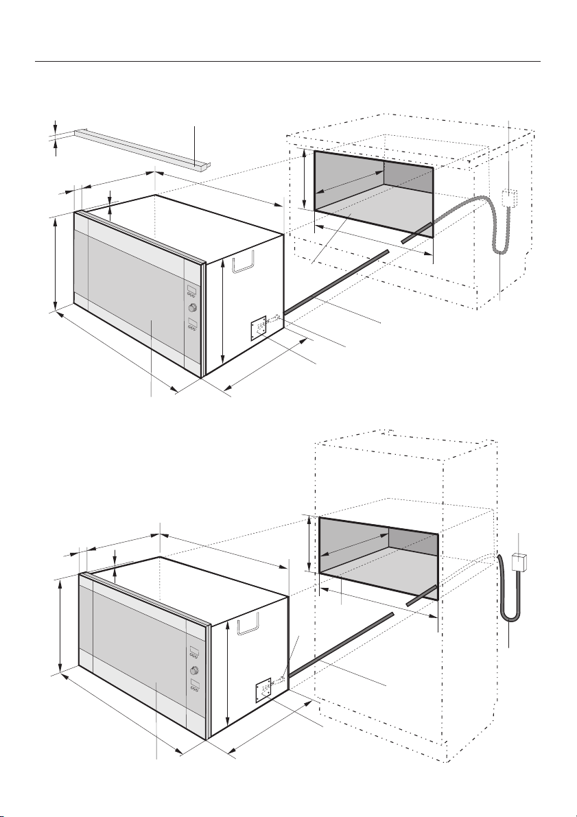
Appliance and building-in dimensions
30
478
20
540
5
895
a
h
845
473
560
516
b
d
550
860
f
e
c
g
20
540
5
845
475
550
860
e
c
478
d
g
473
895
560
h
f
b
4
Page 5

H 399 B
Building in and connecting to
services
a Oven
b Building-in recess with full depth
floor panel
c Inlet for mains connection cable to
the appliance
d Isolator switch position. This should
preferably be located in the housing
unit to the right of the appliance. (Do
not locate the isolator switch behind
the appliance).
e Mains connection cable
f Mains connection cable loop
g Cover panel, behind which the termi-
nals in the appliance are located.
h Filler strip HAL 90
Filler strip h is only required when
fitting an H 399 B into a base unit. It
is available to order through the
Spare Parts Dept.
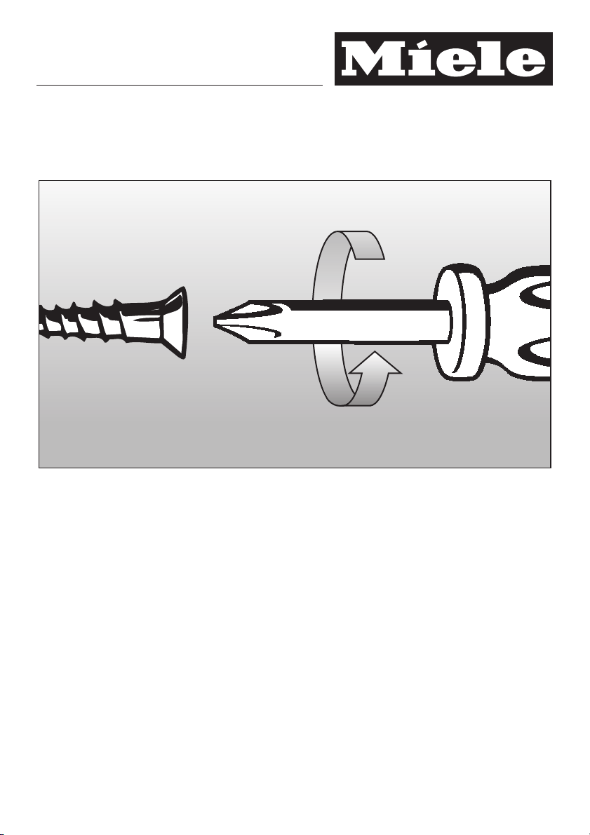
The filler strip is secured, as illus
^
trated, to the underside of the
worktop inside the building-in recess.
Turn off the power supply at the isola
^
tor switch. See "Electrical connec
tion".
Open cover panel g and connect
^
mains connection cable e to the iso
lator switch d, and then to the termi
nal block in the oven a.
See "Electrical connection" for connec
tion diagram.
-
-
-
-
-
-
30
44
478
h
478
473
516
5
Page 6

H 399 B
Securing the oven
i
i
^ Taking care not to trap or damage the
connection cable push the oven into
the recess up to the wooden trans
port protection i.
-
After it has been aligned the oven must
be secured in the housing unit.
j
j
Fit the fixing screws j (supplied) into
^
the vertical strip on the left hand side
of the appliance as shown in the illus
tration.
^ Reconnect the mains electricity sup-
ply to the isolator switch. See "Electrical connection" for further details.
^ Check all the appliance functions us-
ing the Operating Instructions supplied.
-
^
Remove the transport protection i
(see illustration), push the oven com
pletely into the recess and align it.
6
-
Page 7

Electrical connection
Electrical connection UK/ZA
All electrical work should be under
taken by a suitably qualified and
competent person in strict accor
dance with national and local safety
regulations.
Installation, repairs and other work
by unqualified persons could be
dangerous. The manufacturer can
not be held responsible for un
authorised work.
Ensure power is not supplied to the
appliance while installation or repair
work is being carried out.
The appliance must only be operated when built-in. This is to ensure
that all electrical parts are shielded.
Live parts must not be exposed.
The voltage, rated load and fusing are
given on the data plate, visible inside
the side compartment. Ensure that
these match the household mains sup
ply. Please quote these data, and the
model and serial number when contact
ing the Service dept.
-
-
-
-
Connection of this appliance should be
made via a suitable isolator which com
plies with national and local regulations
and the on/off switch should be easily
accessible after the appliance has
been built in.
If the socket is not accessible after in
stallation (depending on country) an
additional means of disconnection must
be provided for all poles.
For extra safety it is advisable to install
a residual current device with a trip cur
rent of 30 mA (in accordance with DIN
VDE 0664, VDE 0100 Section 739).
When switched off there must be an
all-pole contact gap of 3 mm in the isolator switch (including switch, fuses and
relays according to EN 60 335).
-
-
-
-
-
7
Page 8

Electrical connection
Important U.K.
This appliance is designed for connec
tion to a single phase 230-240 V 50 Hz
supply using a suitable 3-core cable.
The wires in the mains lead are col
oured in accordance with the following
code:
Green/yellow = earth
Blue = neutral
Brown = live
In other countries check these details
with your supplier.
WARNING
THIS APPLIANCE MUST BE
EARTHED
-
-
8
Page 9

Connection diagram
Important
The electrical safety of this appliance
can only be guaranteed when continu
ity is complete between the appliance
and an effective earthing system, which
complies with local and national regulations. It is most important that this basic
safety requirement is tested by a qualified electrician. The manufacturer cannot be held responsible for the consequences of an inadequate earthing system such as an electric shock.
-
Electrical connection
The manufacturer can assume no responsibility for damage which is the direct or indirect result of incorrect instal
lation or connenction.
-
91011
Page 10

Page 11

Page 12

Alteration rights reserved /
M.-Nr. 05 741 720 / V03
This paper consists of cellulose which has been bleached without the use of chlorine.
 Loading...