

Page 1

TECHNICAL INFORMATION
Master Chef (30”) Ovens
Includes: H394B, H395B, H395BP, H396B, H396BP,
H397B2, H397BP2, H398B2 & H398BP2
© 2004 Miele
Page 2

Page 3
Master Chef Ovens – Table of Contents
1.0 CONSTRUCTION & DESIGN
1.1 Summary of Model Numbers 1
1.2 Appliance Overview 3
1.2.1 Appliance Overview – Single Oven 3
1.2.2 Appliance Overview – Double Oven 4
1.3 Overview of User Controls 5
1,3,1 Overview of Controls – Single Oven 5
1.3.2 Overview of Controls – Double Oven 6
1.4 Dimensions 6
1.4.4 Dimensions – Single Oven 7
1.4.2 Dimensions – Double Oven 8
1.5 Component Overview 9
1,5,1 Component Overview – Single Oven w/o Master Chef Menu 9
1.5.2 Component Overview – Single oven w/ Master Chef Menu 10
1.5.3 Component Overview – Double Oven – w/o Self Clean 11
1.5.4 Component Overview – Double Oven w/ Self Clean 13
2.0 INSTALLATION
2.1 Electrical Connection 16
2.1.2 Electrical Connection – Operational 16
2.1.2 Electrical Connection – Demo / Showrooms 16
2.2 Installation Guide 17
3.0 COMMISSION and OPERATION
3.1 General Operation 19
3.2 Turning off the oven 19
3.3 Power Failures 19
3.4 Special Features 20
3.4.1 Self Clean (Self Clean Models Only) 20
3.4.2 Door Lock (Self Clean Models Only) 20
3.4.3 Master Chef (all models except H394) 20
2.4.4 Child Safety Lock (all models) 21
Page 4

4.0 DESCRIPTION of FUNCTION
4.1 Cooling Fan - Specifications 24
4.2 Cooling Air Intake 24
4.3 Vapor Intake 24
4.4 Cooling Air Path 24
4.5 Cooling Air Exit 24
4.6 Door Contact Switch (1S24 & 2S24) 24
4.7 Heating Elements 25
4.7.1 Heating Element Activation 25
4.8 Automatic / Safety Shutdown 26
4.9 Cavity Temperature Sensor (1R30 & 4R30) 26
4.10 Roast Probe (2R30 & 5R30) 27
4.11 Self Clean Temperature Sensor (3R30 & 6R30) 27
4,12 Thermal Cut-Outs (1F1 & 3F1) 28
4.12.1 Thermal Cut-Outs (2F1 & 4F1) (Self Clean Models Only) 28
4.13 Convection Fan 28
4.14 Rotisserie Motors (1M15 & 2M15) (all models except H394) 28
4.15 Oven Cavity Lights 28
4.16 Automatic Door Lock (Self Clean Models Only) 29
5.0 SERVICE and MAINTENANCE
5.1 Cleaning & Care Information 31
5.1.1 Perfect Clean 31
5.1.2 Manually Cleaning the Oven Cavity 31
5.2 Front Door – Removal 32
5.3 Runners – Removal 33
5.4 Halogen Light Bulb – Replacement 33
5.5 Removing the Appliance for Service 35
5.6 Control Panel – Removal 35
5.7 Safety Cover - Removal 35
5.8 Top Cover – Removal 37
5.9 Upper Back Panel (Double Ovens) – Removal 37
5.10 Lower (or Single Oven) Back Panel – Removal 37
5.11 Upper (Double Oven) Side Covers - Removal 37
5.12 Lower (or Single Oven) Side Covers – Removal 38
Page 5
5.0 SERVICE and MAINTENANCE (Continued)
5.13 Air Shield (Double Ovens) - Removal 38
5.14 Upper (or Single Oven) Cooling Fan - Removal 39
5.15 Lower Oven (Double Oven) Cooling Fan – Removal 40
5.16 Door Latch – Manual Release (Self Clean Models) 41
5.17 Upper Door Latch Drive Motor & Switch (Double Oven w/ Self Clean) - Removal 42
5.18 Lower Door Latch Drive Motor & Switch (Double Oven w/ Self Clean) - Removal 43
5.19 Upper (or Single Oven) Door Latch & Switch, Door Close Switch – Access 44
5.20 Lower (Double Oven) Door Latch & Switch, Door Close Switch – Access 46
5.21 Oven Cavity Back Panel – Removal 47
5.22 Top Heater / Broiler Heating Element – Removal 48
5.23 Convection Heating Element – Removal 49
5.24 Convection Fan – Removal 50
5.25 Operational Temperature Sensor – Removal 51
5.26 Self Clean Temperature Sensor – Removal 51
5.27 Self Clean Temperature Sensor Resistance Value Test 52
5.28 Rotisserie Motor(s) – Removal 52
5.29 Catalyst Insert (Self Clean Models Only) – Removal 53
5.30 Front Door, Outer Glass Pane – Removal 54
5.31 Front Door , Middle Glass Pane – Removal 55
5.32 Front Door, Interior Glass Pane – Removal 56
5.33 Door Hinge(s) – Removal 57
6.0 FAULT DIAGNOSIS
6.1 Service Mode 59
6.2 Programming Mode 62
6.3 Fault Code Summary 65
6.4 Electronic Boards – Layout 66
6.4.1 Main Electronic 66
6.4.2 Display Electronic 66
Page 6
Master Chef Ovens - List of Figures
1-1 Overview of Single Oven 3
1-2 Overview of Double Oven 4
1-3 Single Oven Controls 5
1-4 Overview of Double Oven Controls 6
1-5 Dimensions of Single Ovens 7
1-6 Dimensions of Double Oven 8
1-7 Component Overview – Single Oven w/o Master Chef Menu 9
1-8 Component Overview – Single Oven w/ Master Chef and Self Clean 10
1-9 Component Overview – Double Oven w/o Self Clean 11
1-10 Component Overview – Double Oven w/ Self Clean 13
2-1 Miele Installation Manual (Cover) 15
2-2 Electrical Connection – Operational 16
2-3 Electrical Connection – Demo / Showrooms 16
2-4 Installation Guide (overview sheet) 17
3-1 Power Failure Message Displayed 19
4-1 Airflow Paths 23
4-2 Upper Heater Element Cavity Temperature Sensor 26
4-3 Roast Probe 27
4-4 Self Clean Temperature Sensor & Catalyst Vapor Outlet 27
4-5 Convection Airflow 28
4-6 Door Locking Components (Self Clean Models Only) 29
5-1 Door Hinge Locking Tabs 32
5-2 Removing the Runners From the Oven Cavity 33
5-3 Prying the Light Cover Off 33
5-4 Sliding the Light Cover from the Clamps 34
5-5 Control Panel, Safety Panel & Top Cover Retaining Screws 36
5-6 Air Shield Panel 38
5-7 Upper (or Single Oven) Cooling Fan 39
5-8 Lower Oven Cooling Fan 40
5-9 Manual Release of the Door Latch (Self Clean Models Only) 41
5-10 Door Latch Drive Motor Assembly (Self Clean Models Only) 42
5-11 Door Latch and Cable (Self Clean Models Only) 43
5-12 Upper (or Single) Housing Retaining Screws 44
5-13 Door Latch Assembly 45
Page 7
Master Chef Ovens - List of Figures (Continued)
5-14 Lifting / Separating the Housing (Double Ovens) 46
5-15 Removing the Oven Cavity Back Pane 47
5-16 Top Heating Element 48
5-17 Convection Fan and Heater Element 49
5-18 Convection Fan Motor and Retaining Screws 50
5-19 Self Clean Temperature Sensor Removal 51
5-20 Rotisserie Motor and Retaining Screws 52
5-21 Catalyst Insert – Removal 53
5-22 Front Door, Outer Glass Removal Position 54
5-23 Front Door, Middle Glass Pane Removal 55
5-24 Front Door, Interior Glass Pane Removal 56
5-25 Door Hinge Removal 57
6-1 Main Electronic Layout 66
6-2 Display Electronic Layout 66
Master Chef Ovens - List of Tables
2-1 Summary of Model Numbers 1
4-1 Cooling Fan Specifications 24
4-2 Heater Element Specifications 25
4-3 Heater Element Operation 25
4-4 Automatic Safety Shutdown Durations 26
5-1 Self Clean Temperature Sensor Resistance Values 52
6-1 Service Mode Navigation (1 of 2) 60
6-2 Service Mode Navigation (2 of 2) 61
6-3 Programming Mode Navigation 63
6-4 Summary of Fault Codes 65
Page 8

This page intentionally left blank.
Page 9
Master Chef Ovens
1.0 Construction and Design
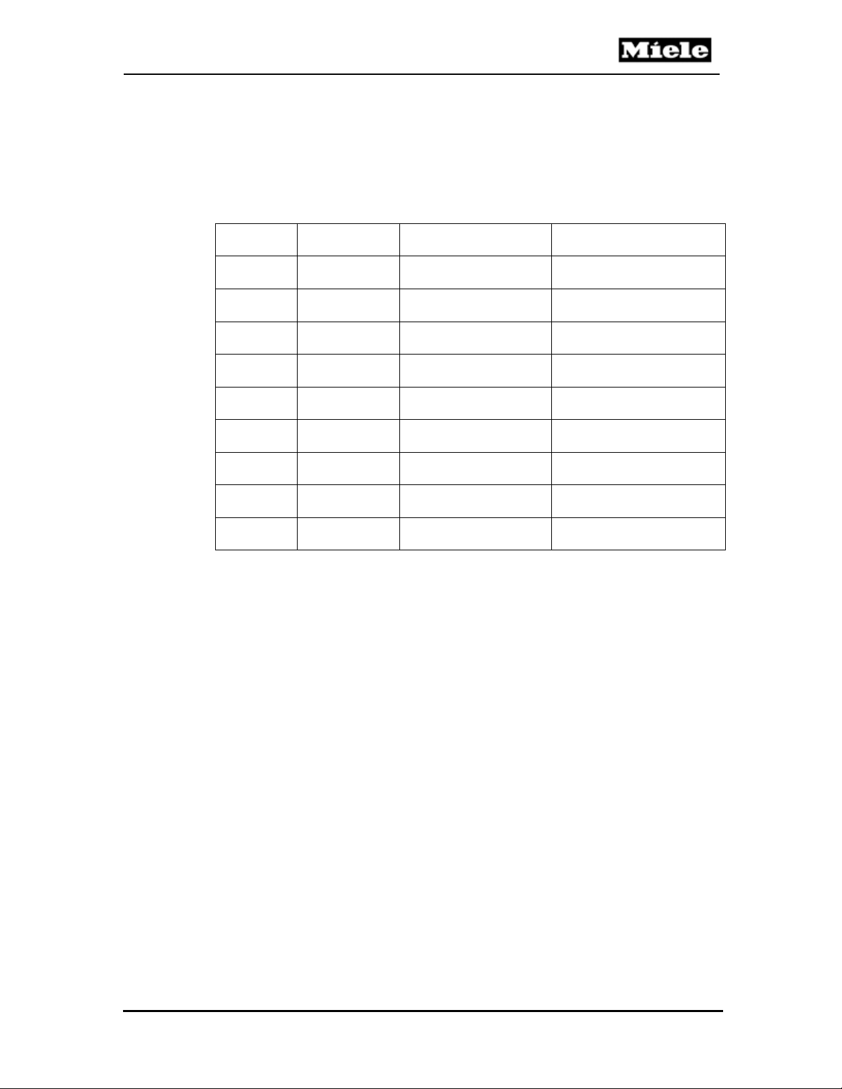
1.1 Summary of Model Numbers
Model
Number
Oven Type Self Clean Mode
Technical Information
Master Chef
Menu System
H394B
H395B
H395BP
H396B
H396BP
H397B2
H397BP2
H398B2
H398BP2
Table 1-1: Summary of Model Numbers
Single - -
Single - Yes
Single Yes Yes
Single - Yes
Single Yes Yes
Double - Yes
Double Yes Yes
Double - Yes
Double Yes Yes
1
Page 10

Technical Information
This page intentionally left blank.
Master Chef Ovens
2
Page 11
Master Chef Ovens
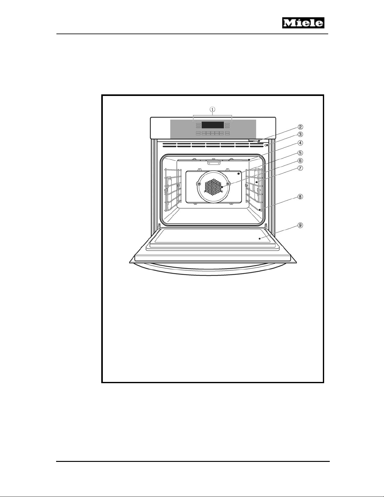
1.2 Appliance Overview
1.2.1 Appliance Overview - Single Ovens (Typical)
1. Control panel
2. Child safety lock
3. Door contact switch
4. Upper heating element
5. Catalytic liner
6. Convection fan
7. Light
8. Non-tip, six lev el runners
9. Oven door
Figure 1-1: Overview of Single Oven
Technical Information
3
Page 12
Technical Information
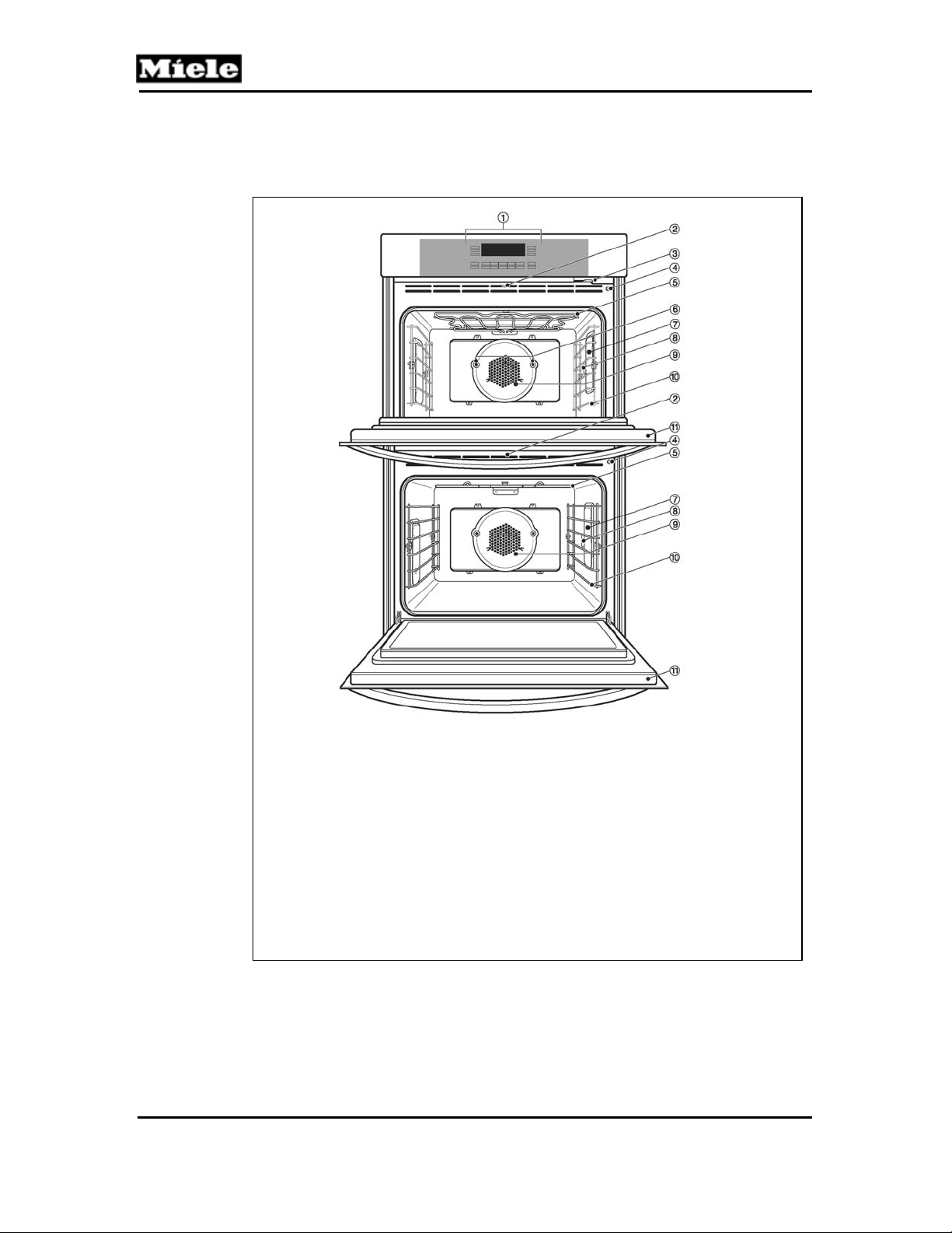
1.1.2 Appliance Overview – Double Oven (Typical)
1. Control Panel
2. Door Lock
3. Child Safety Lock
4. Door Contact Switch
5. Upper Heating Element
6. Rotisserie Motors
7. Light
8. Roast Probe Socket
9. Convection Fan
10. Six-level runners
11. Oven Door
Figure 1-2: Overview of Double Oven
Master Chef Ovens
4
Page 13
Master Chef Ovens
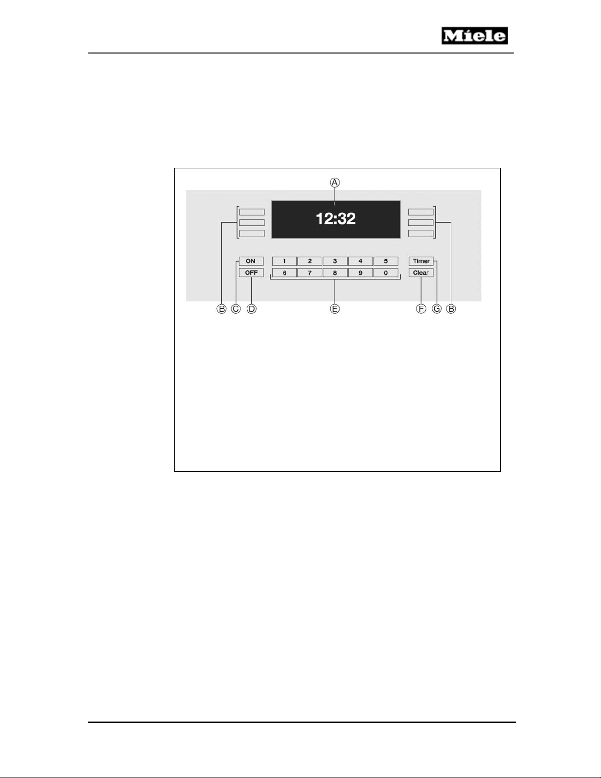
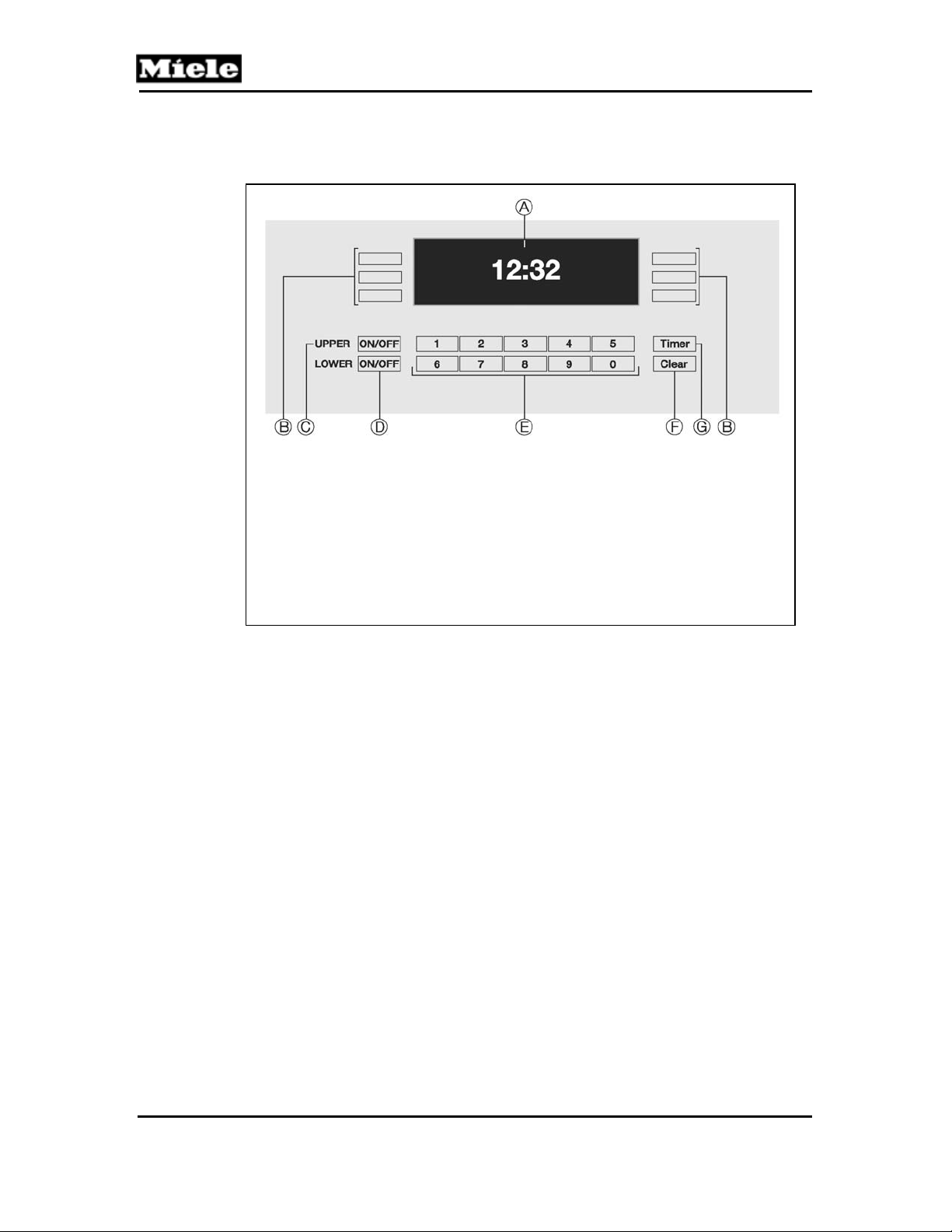
1.3 Overview of User Controls
1.3.1 Single Oven Controls
A. Display: shows the time or the functions.
B. Touch controls: to select or set a function.
C. ON: to turn the oven on.
D. OFF: to turn the oven off.
E. Keypad: to enter times or temperatures.
F. Clear: to delete the last entry or to clear menu items.
G. Timer: to set a timer independent of an oven function.
Figure 1-3: Overview of Single Ov en Controls
Technical Information
5
Page 14
Technical Information
1.3.2 Double Oven Controls
A. Display: shows the time, oven status, or menu options.
B. Touch controls: used to select an option
C. ON/OFF: turns the upper oven on/off.
D. ON/OFF: turns the lower oven on/off.
E. Keypad: used to enter times or temperatures.
F. Clear: deletes the last entry or clears the menu.
G. Timer: used to set up to 2 independent cooking timers.
Figure 1-4: Overview of Double Oven Controls
Master Chef Ovens
6
Page 15
Master Chef Ovens
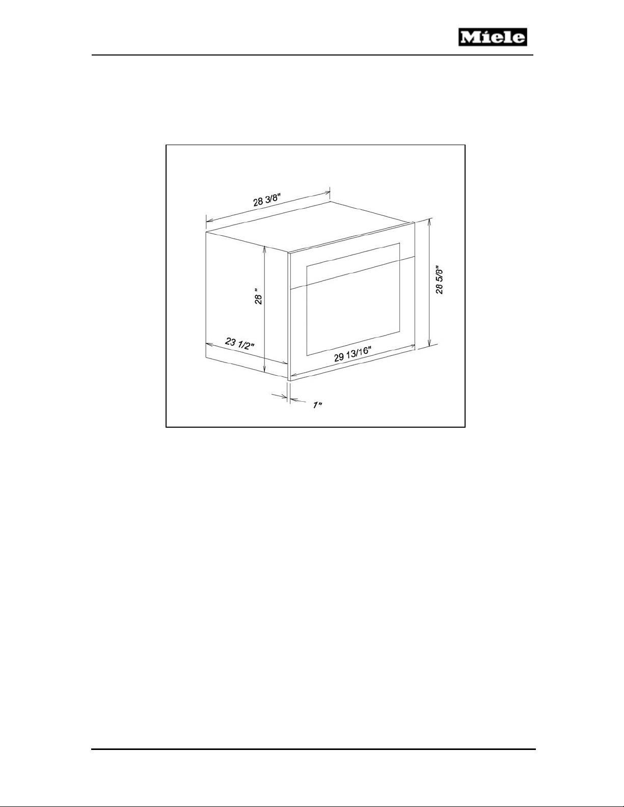
1.4 Dimensions
1.4.1 Dimensions – Single Oven
Figure 1-5: Dimensions – Single Oven
Technical Information
7
Page 16
Technical Information
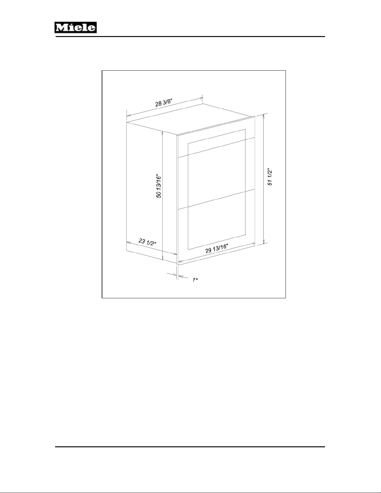
1.4.2 Dimensions – Double Oven
Figure 1-6: Dimensions – Double Oven
Master Chef Ovens
8
Page 17
Master Chef Ovens
Technical Information
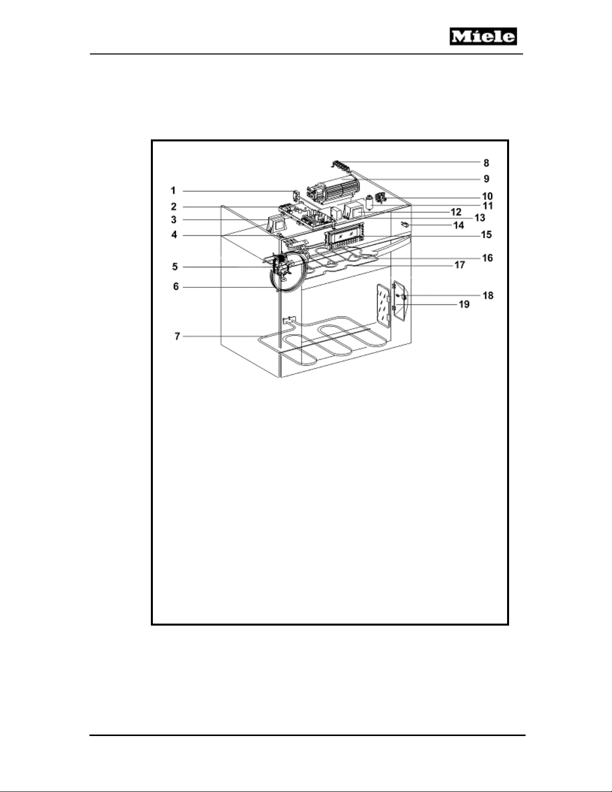
1.5 Components Overview
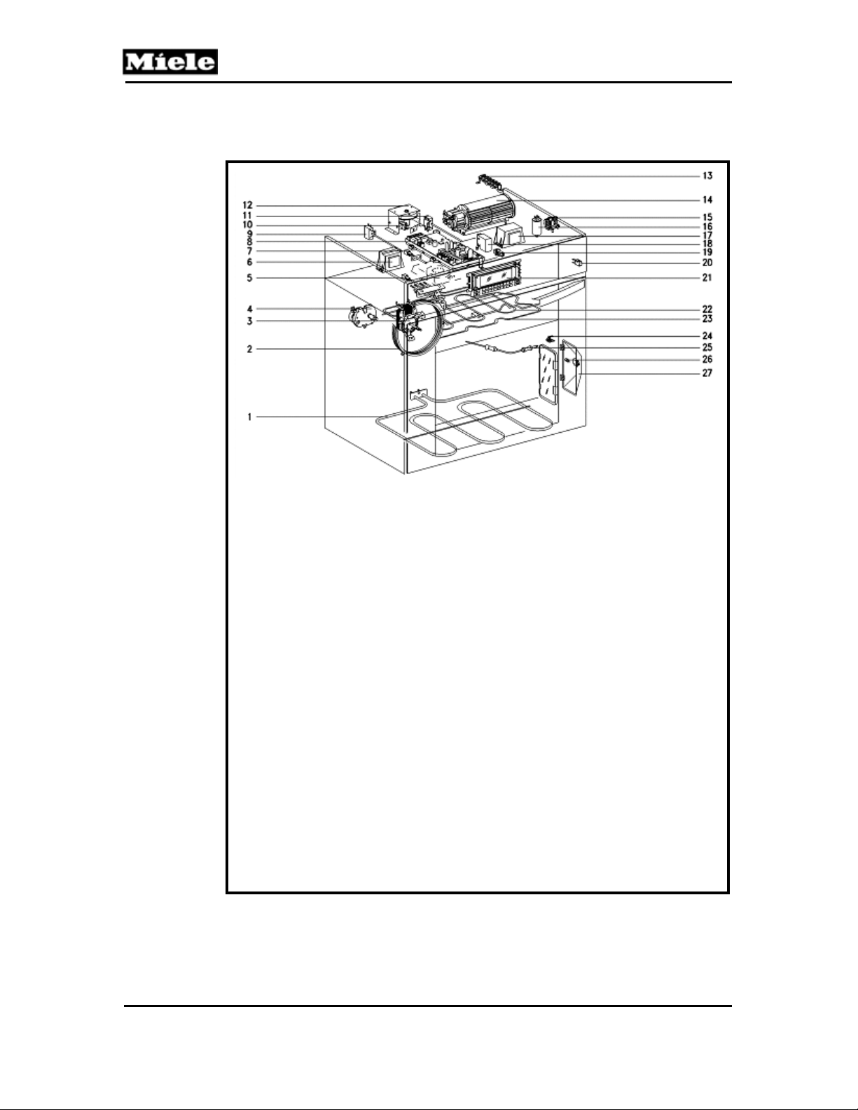
1.5.1 Component Overview – Single Oven, w/o Master Chef Menu
1 (1F1) Hi-Limit Cutoff
2 (1N1) Electronic Unit
3 (2T1) Light Transformer
4 (1R30) Upper Oven Temperature Sensor
5 (1M2) Convection Fan
6 (R14) Convection Heating Element
7 (R12) Lower Heating Element
8 (X3/1) Terminal Block
9 (1M/1) Oven Cooling Fan
10 (S1) Child Safety Switch
11 (Z2) Interference Suppression Capacitor
12 (1T1) Transformer
13 (1K1) Oven Relay
14 (S24) Door Switch
15 (1A1, 2A1) Display Electronic
16 (R15) Broiler Element
17 (R13) Upper Heating Element
18 Halogen Bulb
19 (1H3/1 & 2H3/1) Light Assembly (1 per side)
Figure 1-7: Component Ov erview – Single Oven without Master Chef Menu
9
Page 18
Master Chef Ovens
Technical Information
1.5.2 Component Overview – Single Oven, with Master Chef Menu
1 (R12) Lower Heating Element
2 (R14) Convection Heating Element
3 (1M2) Convection Fan
4 (1M15, 2M15) Rotisserie Motors
5 (1R30) Oven Temperature Sensor
6 (2T1) Light Transformer
7 (3R30) Pyrolytic PTC Sensor (P series only)
8 (1N1) Electronic Unit
9 (1F1) Hi-Limit Cutoff
10 (1S60) Interlock Switch
11 (1F1) Hi-Limit Cutoff
12 (1M23) Door Lock Motor (P series only)
13 (X3/1) Terminal Block
14 (1M/1) Oven Cooling Fan
15 (S1) Child Safety Switch
16 (Z2) Interference Suppression Capacitor
17 (1T1) Transformer
18 (1K1) Oven Relay
19 (2S60) Interlock Switch
20 (S24) Door Switch
21 (1A1, 2A1) Display Electronic
22 (R15) Broiler Element
23 (R13) Upper Heating Element
24 (1X5/8) Connector - Temperature Probe
25 (2R30) Temperature Probe
26 Halogen Bulb
27 (1H3/1 & 2H3/1) Light Assembly
Figure 1-8: Component Overview – Single Oven with Master Chef Menu
(Self Clean (P) Model Shown.
10
Page 19
Master Chef Ovens
Technical Information
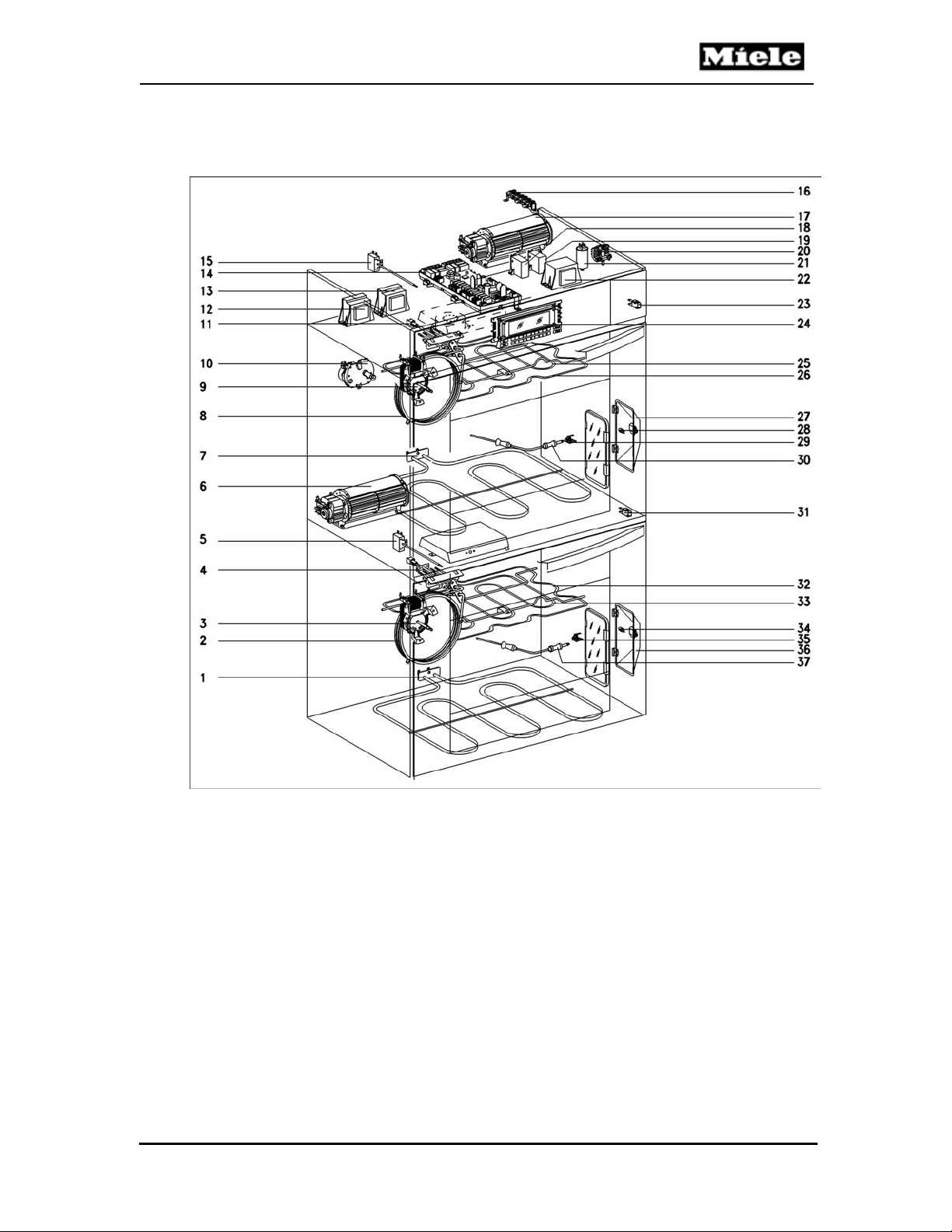
1.5.3 Component Overview – Double Oven, without Self Clean
Figure 1–9: Component Overview – Double Oven, without Self Clean
11
Page 20

Technical Information
Component Overview – Double Oven, without Self Clean
1 (2R12) Lower Oven - Lower Heating Element
2 (2R14) Lower Oven - Convection Heating Element
3 (2M2/2) Lower Oven - Convection Fan
4 (4R30) Lower Oven - Cavity Temperature Sensor
5 (3F1) Lower Oven - Hi-Limit Cutoff
6 (2M2/1) Lower Oven - Cooling Fan
7 (1R12) Upper Oven - Lower Heating Element
8 (1R14) Upper Oven - Convection Heating Element
9 (1M2/2) Upper Oven - Convection Fan
10 (1M15, 2M15) Rotisserie Motors
11 (1R30) Upper Oven - Cavity Temperature Sensor
12 (2T1) Upper Oven - Light Transformer
13 (3T1) Lower Oven - Light Transformer
14 (1N1) Main Electronic Unit
15 (1F1) Upper Oven - Hi-Limit Cutoff
16 (X3/1) Terminal Block
17 (1M2/1) Upper Oven - Cooling Fan
18 (1K1) Upper Oven - Relay
19 (2K1) Lower Oven - Relay
20 (S1) Child Safety Switch
21 (Z2) Interference Suppression Capacitor
22 (1T1) Transformer
23 (1S24) Upper Oven - Door Switch
24 (1A1, 2A1) Display Electronic
25 (1R15) Upper Oven - Broiler Heating Element
26 (1R13) Upper Oven - Upper Heating Element
27 (1H3/1, 2H3/1) Upper Oven - Light Assembly
28 Upper Oven - Halogen Bulb
29 (1X5/8) Upper Oven - Roast Probe Connection
30 (2R30) Upper Oven - Roast Probe
31 (2S24) Lower Oven - Door Switch
32 (2R13) Lower Oven - Upper Heating Element
33 (2R15) Lower Oven - Broiler Heating Element
34 Lower Oven - Halogen Bulb
35 (2X5/8) Lower Oven - Roast Probe Connection
36 (3H3/1, 4H3/1) Lower Oven - Light Assembly
37 (5R30) Lower Oven - Roast Probe
Master Chef Ovens
12
Page 21
Master Chef Ovens
Technical Information
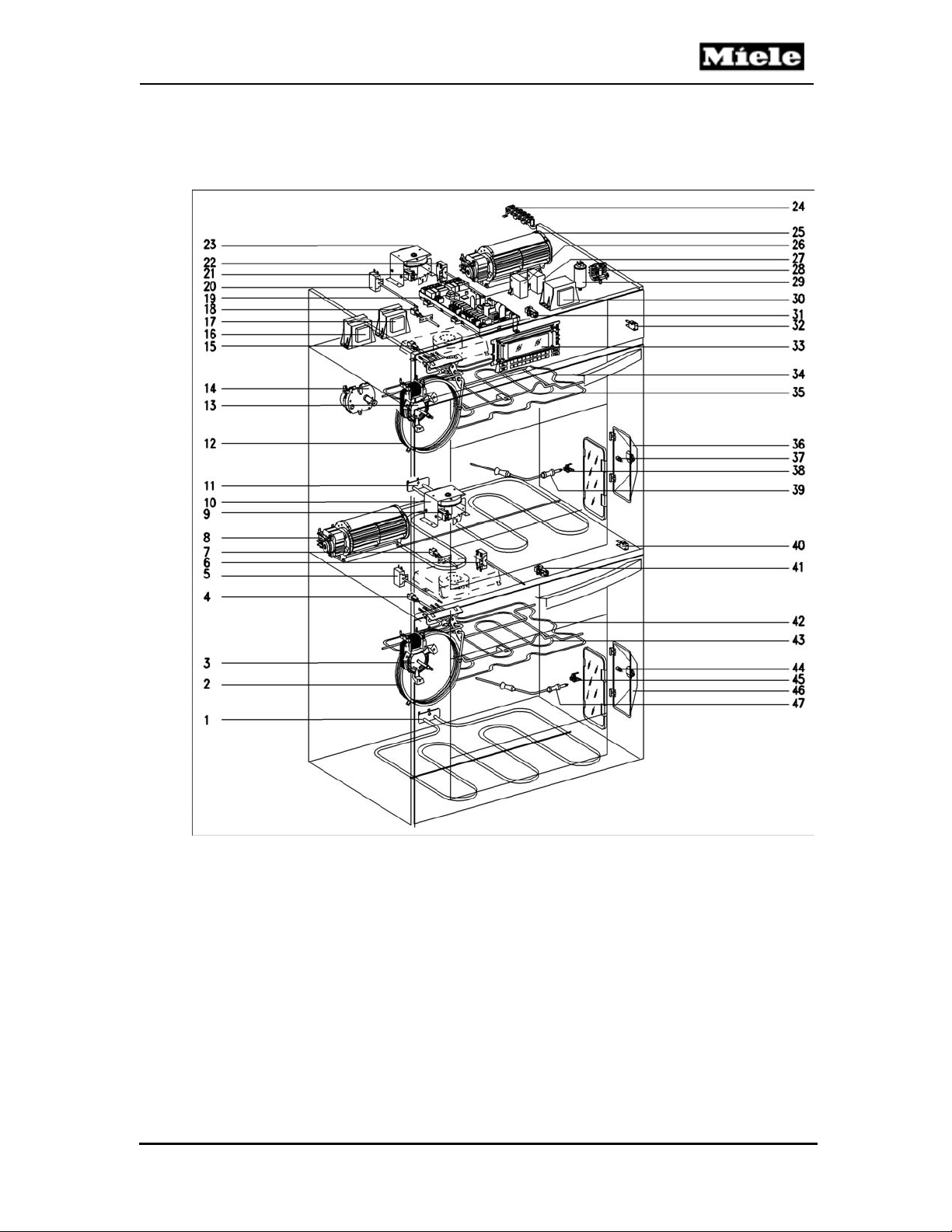
1.5.4 Component Overview – Double Oven, with Self Clean
Figure 1-10: Component Overview – Double Oven, with Self Clean
13
Page 22
Technical Information
Component Overview – Double Oven, with Self Clean
1 (2R12) Lower Oven Lower Heating Element
2 (2R14) Lower Oven Convection Heating Element
3 (2M2/2) Lower Oven Convection Fan
4 (4R30) Lower Oven Cavity Temperature Sensor
5 (3F1) Lower Oven Hi-Limit Cutoff
6 (4F1) Lower Oven Hi-Limit Cutoff (Self Clean)
7 (6R30) Lower Oven Catalyst Temperature Sensor
8 (2M2/1) Lower Oven Cooling Fan
9 (3S60) Lower Oven Interlock Switch
10 (2M23) Lower Oven Door Lock Motor
11 (1R12) Upper Oven Lower Heating Element
12 (1R14) Upper Oven Convection Heating Element
13 (1M2/2) Upper Oven Convection Fan
14 (1M15, 2M15) Upper Oven Rotisserie Motors (2)
15 (1R30) Upper Oven Cavity Temperature
16 (2T1) Upper Oven Light Transformer
17 (3T1) Lower Oven Light Transformer
18 (3R30) Upper Oven Catalyst Temperature Sensor
19 (1N1) Main Electronic
20 (1F1) Upper Oven Hi-Limit Cutoff
21 (1S60) Upper Oven Interlock Switch
22 (2F1) Upper Oven Hi-Limit Cutoff (Self Clean)
23 (1M23) Upper Oven Door Lock Motor
24 (X3/1) Main Terminal Block
25 (1M2/1) Upper Oven Cooling Fan
26 (1K1) Upper Oven Relay
27 (2K1) Lower Oven Relay
28 (S1) Main Child Safety Switch
29 (Z2) Main Interference Capacitor
30 (1T1) Transformer
31 (2S60) Upper Oven Interlock Switch
32 (1S24) Upper Oven Door Switch
33 (1A1, 2A1) Display Electronics
34 (1R13) Upper Oven Upper Heating Element
35 (1R15) Upper Oven Broiler Heating Element
36 (1H3/1, 2H3/1) Upper Oven Light Assembly
37 Upper Oven Halogen Bulb
38 (1X5/8) Connector Upper Oven Temperature Sensor Probe
39 (2R30) Upper Oven Temperature Sensor Probe
40 (2S24) Lower Oven Door Switch
41 (4S60) Lower Oven Interlock Switch
42 (2R13) Lower Oven Upper Heating Element
43 (2R15) Lower Oven Broiler Heating Element
44 Lower Oven Halogen Bulb
45 (2X5/8) Connector Lower Oven Temperature Sensor Probe
46 (3H3/1, 4H3/1) Lower Oven Light Assembly
47 (5R30) Lower Oven Temperature Sensor Probe
Master Chef Ovens
14
Page 23
Master Chef Ovens
2.0 Installation
This section only covers partial installation information.
For complete installation procedures refer to the Miele Installation
Instructions Manual, or model specific Operating Manual.
Figure 2-1: Miele Installation Instructions Manual
Technical Information
15
Page 24
Technical Information
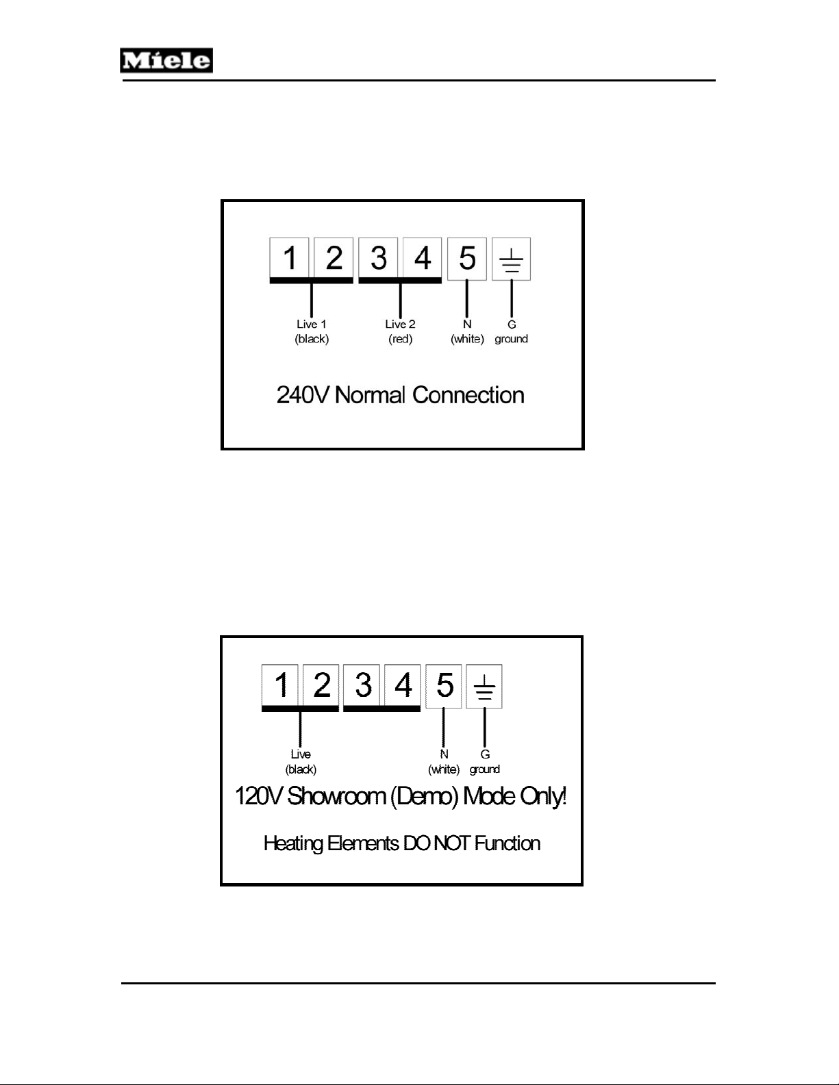
2.1 Electrical Connection
2.1.1 Electrical Connection – Operational
Figure 2-2: Electrical Connection – Operation
2.1.2 Electrical Connection – Demo / Showrooms
For demonstration purposes the oven can be connected to 120 VAC.
With this connection the appliance appears to operate, however heating
is not activated. This allows features such as Master Chef to be
demonstrated to customers.
Master Chef Ovens
Figure 2-3: Electrical Connection – Demo / Showroom
16
Page 25

Master Chef Ovens
Technical Information
2.2 Installation Guide
A single page Installation Guide is included with each oven.
Figure 2-4: Installation Guide (included with each oven)
17
Page 26

Technical Information
Master Chef Ovens
This page intentionally left blank.
18
Page 27

Master Chef Ovens
3.0 Commission and Operation
3.1 General Operation
To select a program:
1. Touch the “ON” (“ON/OFF” on double ovens) control.
2. Select the desired function (example: BAKE)
3. Select the desired specific operation from the sub-menu (example:
CONVECTION BAKE)
4. Select the temperature (example: 425
3.2 Turning off the oven
To turn off the oven, touch the "OFF" (“ON/OFF” on double ovens)
control. The oven will turn off and the time of day will appear in the
display.
3.3 Power Failures
In the event the oven loses power during operation a “Power Failure”
message is displayed as shown in 3-1.
Figure 3-1: ”Power Failure” message displayed
This message is displayed to advise that the incoming power was
disrupted (power failure, etc.). It does not require any type of technical
service.
The ”Power Failure” message can be cleared by performing the following:
1. Turn the oven on by touching the ON/OFF (“ON/OFF” on double
ovens) control.
2. Turn the oven off by touching the ON/OFF (“ON/OFF” on double
ovens) control.
The message is clears.
11:23 PM
Power Failure
o
)
Technical Information
19
Page 28

Master Chef Ovens
Technical Information
3.4 Special Features
3.4.1 Self Clean Function (P / Self Clean Models Only)
When the Self Clean function is selected, the oven is heated to very high
temperatures to burn off any residue inside the oven cavity.
The duration of the Self Clean function is not a timed function and is
based on the amount of soiling inside the oven cavity. Total time will vary
depending on the condition of the oven interior.
Once the Self Clean Program completes and the oven cools, wipe the
interior clean with a damp cloth to remove any remaining residue.
3.4.2 Door Lock (P / Self Clean Models Only)
The door lock is operated via a motorized control. During the Self Clean
function the door automatically locks after one (1) minute. The door
remains locked until the Self Clean process has completed and the oven
temperature has dropped below 392° F (200° C).
If the Self Clean function is accidentally started, shut off the oven and wait
for the oven temperature to drop and for the door lock to release. This
may take several minutes.
The door lock can be activated while in the Service Mode. See section 6,
Fault Diagnosis.
3.4.3 Master Chef (all Models except H394)
The “Master Chef” menu feature is designed to ease operation and
improve cooking results. This feature uses a list of selectable preset
functions for commonly cooked foods. Users can select the type of food
from a menu and simply reply to a few basic inputs (i.e. weight, etc.) The
oven performs the necessary functions automatically to ensure a perfectly
cooked meal.
20
Page 29

Master Chef Ovens
3.4.4 Child Safety Lock (All Models)
The child safety lock is used to prevent children from operating the oven
or to conserve standby power when the oven will not be used for an
extended period of time.
To activate the child safety lock:
1. Slide the lock to position “O”.
2. The oven cannot be operated & the clock will not be displayed.
To deactivate the child safety lock:
1. Slide the lock to position “I”.
2. The oven can then be operated & the clock will be displayed.
Warning
Using the Child Safety Switch does NOT disconnect all sources of power
within the oven. To safely disconnect power during service shut off the
main supply via the circuit breaker.
Note
For further detailed appliance operation, refer to the Operating Manual for
that model.
21
Technical Information
Page 30

Technical Information
Master Chef Ovens
This page intentionally left blank.
22
Page 31

Master Chef Ovens
4.0 Description of Function
1. Opening between Housing and Upper Holding Plate Insulation Mat
2. Opening between Outer and Interior Glass Pane
3. Opening below the Door
4. Opening between Vent Strip and Bottom Plate
5. Opening between Bottom Plate and Lower Insulation Mat
6. Convection Fan
7. Air Duct
8. Vapor Outlet (H398BP2 Only)
9. Cooling Fan
10. Exhaust Duct
Figure 4-1: Airflow Paths (Double Oven Shown)
23
Technical Information
Page 32

Technical Information
4.1 Cooling Fan – Specifications
Power Requirement
Wattage – Normal Speed
Wattage – High Speed (Self Cleaning)
Table 4-1: Cooling Fan Specifications
4.2 Cooling Air Intake
The Cooling Fan (Figure 4-1, Item 9) takes in the air through the opening
below the Door. The air flows between the Outer and Interior Glass
Panes and into the area between the Housing and Upper Holding Plate
Insulation Mat.
4.3 Vapor Intake
The Cooling Fan takes in the vapor through the Vapor Outlet (Figure 4-1,
Item 8) and the Exhaust Duct (Figure 4-1, Item 10).
4.4 Cooling Air Path
The Cooling Fan moves the air and vapor into the air vents (Figure 4-1,
Item 7) and through the opening between the Bottom Plate and the Lower
Insulation Mat (Figure 4-1, Item 5).
4.5 Cooling Air Exit
The cooling air exits via the opening between the vent strip and bottom
plate (Figure 4-1, Item 4).
4.6 Door Contact Switch (1S24 & 2S24)
The Door switch monitors the opening and closing of the door.
If the door is opened during cooking, the Convection Fan and Heating
Elements for the respective oven are turned off.
Master Chef Ovens
120V / 60 Hz
23 W
65W
24
Page 33

Master Chef Ovens
4.7 Heating Elements
Each oven cavity is equipped with 4 heating elements:
R12 – Lower Element 240V 1851W
R13 – Upper Element 240V 1960W
R14 – Convection 240V 2722W
R15 – Broil Element 240V 2178W
Table 4-2: Heating Element Specifications
4.7.1 Heating Element - Activation
Elements are activated based on the program mode selected.
Program Mode Bottom Top Convection Broil
Convection
Top / Bottom
Browning
Heater Voltage Wattage
Bake
Bake
Heat
X X
X X
X X X X
X X
Technical Information
Rapid
Heat
Intensive
Auto Roast
Convection
Roast
Top / Bottom
Roast
Broil
Maxi Broil
Rotisserie
Convection
Broil
Dehydration
Proof
Defrost
Self Clean
Sabbath
Baking
Table 4-3: Heater Element Operation
X X X
X X
X X
X X X X
X
X X
X X
X
X
X
X
X X X X
25
Page 34

Technical Information
4.8 Automatic / Safety Shutdown
Each program has a maximum operation time. When the maximum
operation time is reached, the oven turns itself off.
Bake 12
Convection Bake 12
Top / Bottom Heat 12
Browning 12
Intensive 6
Auto Roast 12
Convection Roast 12
Top / Bottom Roast 12
Broil 6
Maxi Broil 6
Rotisserie 6
Convection Broil 6
Dehydration 24
Proof 24
Defrost 24
Self Clean N/A
Sabbath Baking 72
Table 4-4: Automatic Safety Shutdown durations
Program Time-Out (in hours)
Master Chef Ovens
4.9 Cavity Temperature Sensor (1R30 & 4R30)
The Oven Cavity Temperature Sensor is located in the guide tube of the
Upper Heating Elements (Figure 4-2, Item 1). The Sensor sends a signal
back to the Main Electronic. The oven cavity temperature is calculated
and displayed via the Display Electronic.
Figure 4-2: Upper Heater Element Cavity
Temperature Sensor
26
Page 35

Master Chef Ovens
Technical Information
4.10 Roast Probe (2R30 & 5R30) (All Models Except H394)
The Roast Probe can be used to monitor the core temperature of meat
and poultry. The long pointed end of the probe is inserted into the thickest
portion of the meat. The short end of the probe is inserted into the roast
probe socket located on the right side of the oven cavity. For optimum
cooking results ensure the probe does not contact any bones within the
meat or poultry.
Figure 4-3: Roast Probe
4.11 Self Clean Temperature Sensor (3R30 & 6R30) (P /
Self Clean Models Only)
The Self Clean Temperature Sensor is located in the Vapor Outlet
(above the Catalyst) and monitors the oven temperature during the Self
Clean Mode. Refer to Figure 4-4.
1. Self Clean Temperature Sensor
2. Catalyst Vapor Outlet
Figure 4-4: Self Clean Temperature Sensor and Catalyst Vapor Outlet
27
Page 36

Technical Information
Master Chef Ovens
4.12 Thermal Cut-Outs (1F1 & 3F1)
Each separate oven cavity is equipped with a High Temperature Thermal
Cut-Out. The cut out is designed to interrupt the power in should the
temperature exceed 680
o
F (360oC) during operation modes.
4.12.1 Thermal Cut-Outs (2F1 & 4F1) (P / Self Clean Models
Only)
Each separate oven cavity is equipped with a High Temperature Thermal
Cut-Out designed to interrupt the power should the temperature exceeds
o
968
F (520oC) during the Self Clean mode.
4.13 Convection Fan (1M2/1 & 2M2/1)
The Convection Fan is mounted to the rear wall of the oven. It
pressurizes a large volume of air in the small cavity located in the rear
wall of the oven to produce true convection.
Figure 4-5: Convection Airflow
4.14 Rotisserie Motors (1M15 & 2M15)
Two 120 VAC Rotisserie Motor are mounted to the rear wall of the oven.
These motors provide drive for the Rotisserie Shafts.
4.15 Oven Cavity Lights
There are two Oven Cavity Lights in each oven. Two Transformers
mounted in the top of the oven power the lights.
Lamp Voltage 12V
Lamp Output 10W
28
Page 37

Master Chef Ovens
Technical Information
4.16 Automatic Door Lock (Self Clean Models Only)
When the Self-Cleaning program begins, the Door Lock Motor activates
and locks the door. The door cannot be opened until the temperature
drops below 398
1. Door Lock Motor (M23) 120V/5W
2. Interlock Switch (1S60)
3. Cable Assembly
4. Door Latch
5. Interlock Switch (2S60)
Figure 4-6: Door Locking Components (Self Clean Models Only)
0
F (2000 C).
29
Page 38

Technical Information
Master Chef Ovens
This page intentionally left blank.
30
Page 39

Master Chef Ovens
5.0 Service and Maintenance
5.1 Cleaning & Care Information
5.1.1 PerfectClean
PerfectClean® is a smooth, nonstick surface that cleans up easily with a
sponge. The following items are coated with the exclusive Miele
"PerfectClean®" finish:
Oven Walls
Roasting Pans
Anti-Splash Tray
Oven Runners
Do not clean PerfectClean items in a dishwasher. Some detergents
contain compounds that could damage the finish.
To properly clean the surfaces, use a sponge and a solution of hot water
and liquid dish soap for cleaning. Do not use abrasive cleaners, ceramic
cleaners, metal scourers, or oven cleaners.
After cleaning, rinse thoroughly with water. The water should run off the
surface easily. Any residue will hinder this effect. Stubborn baked on
grease may need to be soaked first to loosen deposits.
Clean up all spills as soon as possible to prevent stains. Spilled fruit
juices can permanently discolor surfaces; however the discoloration does
not hinder the efficiency of the finish.
5.1.2 Manually Cleaning the Oven Cavity
Danger
Allow the oven to cool before cleaning.
To make cleaning easier
Remove the oven door
Remove the runners
Lower the upper heating element
Clean the oven surfaces with a solution of hot water and liquid dish
soap and a sponge.
Do not use abrasive cleaning agents, hard brushes, metal scouring
pads, steel wool, knives or other abrasive materials.
Do not use oven sprays on any part of this oven.
Dry surfaces before reassembly.
Technical Information
31
Page 40

Technical Information
5.2 Front Door – Removal
Important
DO NOT hold the door by the handle. When handling the door it should
be gripped firmly on the sides (glass and frame).
1. Open the door fully.
2. Flip up the locking clamps on each door hinge.
3. Slowly shut the door until the protruding clamps stop the
movement. Pull the door upward to remove.
Figure 5-1: Door Hinge – Locking Tabs
Master Chef Ovens
32
Page 41

Master Chef Ovens
5.3 Runners – Removal
Figure 5-2: Removing The Runners From The Oven Cavity.
1. Turn the two thumbscrews, (Figure 5-2) counterclockwise and
remove.
2. Pull the runners away from the oven wall to remove.
(Figure 5-2)
5.4 Halogen Light Bulb - Replacement
1. Remove the runners.
2. Spread a dishtowel on the oven floor to protect the enamel, in
case the light cover falls.
3. Insert the supplied lid opener between the light cover and the
metal frame of the light along the edge closest to the oven door.
Figure5-3: Prying The Light Cover Off
Technical Information
33
Page 42

Master Chef Ovens
Technical Information
5.4 Halogen Light Bulb – Replacement (Continued)
4. Carefully pry the light cover out of the metal frame
(Figure 5-3).
5. Slide the light cover out.
Figure 5-4: Sliding light cover from the clamps
Note
Do not bend the metal clamps. Bending the clamps could
damage the clamps and reflector.
6. Replace the halogen bulb.
Note
Only use a 12 V, 10 W, 572°F (300°C) heat resistant,
Osram, type w818 bulb.
Do not touch the new light bulb with your fingers; touching
the bulb will reduce its life.
Put the light cover back in place with the notch to the rear of the
7.
metal clamps.
8. Press the light cover in to the metal frame.
9. Re-Install the runners.
34
Page 43

Master Chef Ovens
5.5 Removing the Appliance for Service
1. Turn off power to the oven via the circuit breaker.
2. Remove Front Door(s) from the oven (Section 5.2)
3. Remove the Installation Screws.
4. Carefully slide the oven out from the cabinets.
5. Lift the oven to remove from the cabinets.
6. Disconnect the electrical connection.
Caution
Use adequate manpower to remove the oven. Ovens can weigh more
than expected.
Note
Ensure the entire bottom of the oven is evenly supported; or the
bottom of the oven can be damaged
5.6 Control Panel - Removal
1. Refer to Figure 5-5.
2. Remove the Front Doors from the oven. (Section 5.2)
3. Remove the Installation Screws.
4. Carefully move the oven outward about 3 inches.
5. Remove the five screws from the underside of the control panel (Item
2).
6. Hold the Control Panel in place and remove the three screws from the
top of the oven (Item 1).
7. Carefully pull away the control panel from the oven, as the connected
wiring is short in length.
5.7 Safety Cover – Removal
1. Refer to Figure 5-5.
2. Remove the Control Panel (Section 5.2).
3. Move the oven outward to allow access to the Safety Cover Retaining
Screws (Item 3).
4. Remove the four screws (Item 3).
5. Pull the Safety Cover away from the oven.
Technical Information
35
Page 44

Technical Information
1. Control Panel Retaining Screws top (3)
2. Control Panel Retaining Screws bottom (5)
3. Safety Cover Retaining Screws (4)
4. Top Cover Screws side (2)
5. Top Cover Screws rear (3)
Figure 5-5: Control Panel, Safety Panel and Top Cover Retaining Screws
Master Chef Ovens
36
Page 45

Master Chef Ovens
Technical Information
5.8 Top Cover - Removal
1. Remove the Front Doors (Section 5.2)
2. Remove the oven (Section 5.5)
3. Remove the Control Panel (Section 5.6)
4. Remove the Safety Cover (Section 5.7)
5. Refer to Figure 5-5, Remove the Top Cover Side Retaining Screws
(Item 4) and the Top Cover Rear Retaining Screws (Item5)
6. Lift the cover from the oven.
5.9 Upper Back Panel (Double Ovens) - Removal
1. Remove the Front Doors (Section 5.2)
2. Remove the oven (Section 5.5)
3. Remove the Control Panel (Section 5.6)
4. Remove the Safety Cover (Section 5.7)
5. Remove the Top Cover (Section 5.8)
6. Remove the twelve Rear Retaining Screws.
7. Remove the two Side Retaining Screws.
8. Slide the panel down while pulling it from the oven.
5.10 Lower (or Single Oven) Back Panel - Removal
1. Remove the Front Doors (Section 5.2)
2. Remove the oven (Section 5.5)
3. Remove the eighteen Rear Retaining Screws.
4. Remove the two Side Retaining Screws.
5. Slide the panel upward while pulling it from the oven.
5.11 Upper (Double Oven) Side Covers - Removal
1. Remove the Front Doors (Section 5.2)
2. Remove the oven (Section 5.5)
3. Remove the Control Panel (Section 5.6)
4. Remove the Safety Cover (Section 5.7)
5. Remove the Top Cover (Section 5.8)
6. Remove the Upper Back Panel (Section 5.9)
7. Remove the Side Cover Retaining Screws.
8. Lift the panel from the oven.
37
Page 46

Master Chef Ovens
Technical Information
5.12 Lower (or Single Oven) Side Covers - Removal
1. Remove the Front Doors (Section 5.2).
2. Remove the oven (Section 5.5).
3. Remove the Lower Back Panel (Section 5.10).
4. Remove the Side Cover Retaining Screws.
5. Lift the panel from the oven.
5.13 Air Shield Panel (Double Ovens) - Removal
1. Remove the Front Doors (Section 5.2).
2. Remove the oven for service (Section 5.5).
3. Remove the Upper Back Panel (Section 5.9)
4. Remove the Lower Back Panel (Section 5.10).
5. Refer to Figure 5-6. Remove the Retaining Screws (Item 2)
6. Remove the Air Shield Panel (Item 1)
Figure 5-6: Air Shield Panel
38
Page 47

Master Chef Ovens
Technical Information
5.14 Upper (or Single Oven) Cooling Fan - Removal
1. Remove the Front Doors (Section 5.2).
2. Remove the oven (Section 5.5).
3. Remove the Upper Back Panel (Section 5.9)
4. Refer to Figure 5-7. Unplug the electrical connections to the Cooling
Fan (Item 1).
5. Remove the Vent Strip Fastening Screws (Items 2 & 3).
6. Remove Vent Strip(s) – as necessary.
7. Remove the Cooling Fan Fastening Screws.
8. Remove the Cooling Fan.
1. Upper Cooling Fan
2. Vent Strip
3. Vent Strip
Figure 5-7: Upper (or Single Oven) Cooling Fan - Removal
39
Page 48

Master Chef Ovens
Technical Information
5.15 Lower Oven Cooling Fan (Double Oven) -
Removal
1. Remove the Front Doors (Section 5.2).
2. Remove the oven (Section 5.5).
3. Remove the Lower Back Panel (Section 5.10)
4. Refer to Figure 5-8. Unplug the electrical connections to the
Cooling Fan (Item1).
5. Remove the Vent Strip Fastening Screws (Items 2 & 3).
6. Remove Vent Strip(s) – as necessary.
7. Remove the Cooling Fan Fastening Screws.
8. Remove the Cooling Fan.
1. Upper Cooling Fan
2. Vent Strip
3. Vent Strip
Figure 5-8: Lower Oven Cooling Fan - Removal
40
Page 49

Master Chef Ovens
Technical Information
5.16 Door Latch - Manual Release (P / Self Clean Models)
Important
Ensure the oven temperature is below 392oF (200oC), and attempt to
unlock the door using the Service Mode (refer to Section 6 Fault
Diagnosis) before performing this procedure.
Refer to Figure 5-9
1. Bend the end of a stiff wire into a 4 hook – as shown.
2. Carefully insert wire between door and control panel.
Caution
Ensure the wire does not contact the coated surfaced, or irreversible
damages to the surface can result.
3. Pull the door latch by moving the wire horizontally to the right.
1. Wire (formed into hook)
2. Door Latch
Figure 5-9: Manual Release Of The Door Latch (Self Clean Models Only)
41
Page 50

Master Chef Ovens
Technical Information
5.17 Upper Door Latch Drive Motor and Door Lock Switch
(1M23 & 1S60) (Double Ovens with Self Clean) Removal
1. Remove the Front Doors (Section 5.2).
2. Remove the oven (Section 5.5).
3. Remove the Upper Back Panel (Section 5.9)
4. Refer to Figure 5-10. Unplug the electrical connections to the Door
Lock Motor (Item 3).
5. Remove the Door Latch Drive Screws (Item 2).
6. Refer to Figure 5-11. Loosen the Cable Nut (Item1).
7. Remove the Cable from the mounting bracket.
Note
When the Cable tension is released, the Oven Door Locks.
1. Door Lock Motor
2. Mounting Screws
3. Electrical Connection
Figure 5-10: Door Latch Driv e Motor Assembly
42
Page 51

Master Chef Ovens
Technical Information
1. Cable
2. Cable Nut
Figure 5-11: Door Latch and Cable
5.18 Lower Door Latch Drive Motor and Door Lock Switch
(2M23 & 3S60) (Double Ovens with Self Clean) Removal
1. Remove the Front Doors (Section 5.2).
2. Remove the oven (Section 5.5).
3. Remove the Upper Back Panel (Section 5.9)
4. Remove the Lower Back Panel (Section 5.10)
5. Refer to Figure 5-10. Unplug the electrical connections to the Door
Lock Drive Motor (Item 3).
6. Remove the Door Latch Drive Fastening Screws (Item 2).
7. Refer to Figure 5-11. Loosen the Cable Nut (Item 1).
8. Remove the Cable from the mounting bracket.
Note
When the Cable tension is released, the Oven Door Locks.
43
Page 52

Master Chef Ovens
Technical Information
5.19 Upper (or Single Oven) Door Latch, Door Lock Switch
and Door Close Switch (2S60 & 1S24) (Self Clean
Models) – Access
1. Remove the Front Doors (Section 5.2)
2. Remove the oven (Section 5.5)
3. Remove the Control Panel (Section 5.6)
4. Remove the Top Cover (Section 5.8)
5. Refer to Figure 5-12. Remove the four Screws (Item 1) that secure the
Upper Housing Assembly to the Cavity Assembly.
Figure 5-12: Upper (or Single Oven) Housing Retaining Screws
Note
Use caution when lifting the front of Upper Housing, as the wiring
is still connected.
Safety Tip
A second person is required to lift the housing or safely secure
the housing into a position during Latch, Door Lock Switch and /
or Door Close Switch service / replacement.
44
Page 53

Master Chef Ovens
Figure 5-13 Door Latch Assembly
6. Refer to Figure 5-13. Remove the two screws that secure the Latch
7. Slightly lift the Upper Housing near the front to access the Latch
Assembly to the Cavity Assembly.
Assembly, as shown in Figure 5-14.
Technical Information
Service Tip - Upper & Lower Door Close Switch Removal
To simplify access to the Door Switch Retaining Tabs, the Right Side
Panel can be removed permitting direct access to the underside of the
locking tabs.
45
Page 54

Technical Information
Master Chef Ovens
5.20 Lower Door Latch, Door Lock Switch and Door Close
1. Door Latch Assembly
2. Door Closed Switch
Figure 5-14: Lifting the front of the Upper Housing to access the Door Lock /
Latch Assembly and Door Closed Switch
Switch (4S60 & 2S24) (Double Oven P/Self Clean
Models) - Access
1. Remove the Front Doors (Section 5.2).
2. Remove the oven (Section 5.5).
3. Remove the Upper Back Panel (Section 5.9)
4. Remove the Lower Back Panel (Section 5.10).
5. Remove the Air Shield Panel (Section 5.13)
6. Refer to Figure 5-13. Remove the two screws that secure the Latch
Assembly to the Cavity Assembly.
7. From the rear of the oven, reach into the Air Shield Opening to access
the Door Lock Switch and Door Closed Switch.
46
Page 55

Master Chef Ovens
Technical Information
5.21 Oven Cavity Back Panel - Removal
1. Remove the Front Door(s) (Section 5.2)
2. Refer to Figure 5-15. Remove the four screws from the panel (Item 1).
3. Pull the back panel forward to remove from the oven (Item 2).
Figure 5-15: Removing the Oven Cavity Back Panel
Note
When removing the back panel use care not to make contact with the
oven interior surfaces. Protect the interior of the oven as necessary.
47
Page 56

Technical Information
5.22 Top Heater/Broiler Heating Element
(1R13/1R15, 2R13/2R15) - Removal
1. Refer to Figure 5-16.
2. Remove the Heater Element Retaining Screws (Item 1).
3. Remove the Thumb Screw (Item 2).
1. Top Heating Element Retaining Screws
2. Thumb Screw
3. Temperature Sensor Connection
Figure 5-16: Top Heating Element
Gently lift the mounting flange upward and move it toward the front of
4.
the oven.
5. Disconnect the Temperature Sensor Connection (Item 3).
6. Remove the Temperature Sensor.
7. Disconnect the Heater Element connections.
8. Remove the Heater Element.
Master Chef Ovens
48
Page 57

Master Chef Ovens
5.23 Convection Heating Element - Removal
(1R14, 2R14)
1. Refer to Figure 5-17.
2. Remove the Front Doors (Section 5.2).
3. Remove the oven (Section 5.5).
4. Remove the Oven Cavity Back Panel (Section 5.21)
5. Remove the Back Panel (Section 5.9 and / or 5.10)
6. Note the position of the electrical connections to the element.
7. Unplug the electrical connections from the element.
8. Access the oven cavity and Remove the Heating Element Retaining
Screws (Item 1).
9. Remove the Heating Element.
1. Retaining Screws
2. Convection Fan Retaining Nut
3. Convection Fan Shaft Washer
4. Convection Fan Shaft Bushing
Figure 5-17: Convection Fan and Heating Element Hardware
Technical Information
49
Page 58

Master Chef Ovens
Technical Information
5.24 Convection Fan – Removal (1M2/2, 2M2/2)
1. Refer to Figure 5-17.
2. Remove the Front Doors (Section 5.2).
3. Remove the oven (Section 5.5).
4. Remove the Back Panel (Section 5.9 and / or 5.10)
5. Remove the Oven Cavity Back Panel (Section 5.21)
6. Loosen the Fan Blade Nut (Item 2).
Note
The Fan Blade Nut is reverse thread.
7. Remove Fan Blade, Washer (Item 3) and Bushing (Item 4).
8. Refer to Figure 5-18. Remove the three Retaining Screws.
9. Unplug the electrical connection. Remove the component.
Figure 5-18: Convection Fan Motor and Retaining Screws
50
Page 59

Master Chef Ovens
Technical Information
5.25 Operational Temperature Sensor (1R30 & 4R30)
– Removal
Refer to: Top Heater/Broiler Heating Element – Removal (Section 5.22)
5.26 Self Clean Temperature Sensor (3R30 & 6R30)
– Removal (P/Self Clean Models)
1. Remove the Front Doors (Section 5.2).
2. Remove the oven (Section 5.5).
3. Remove the Back Panel(s) – as necessary (Section 5.9 and /or 5.10)
4. Disconnect the electrical connection.
5. Refer to Figure 5-19. Move the retaining spring to the side and
remove the Sensor (Item 1) from the Catalyst Vapor Outlet .
1. Self Clean Temperature Sensor
2. Catalyst Vapor Outlet
Figure 5-19: Self Clean Temperature Sensor Removal
51
Page 60

Master Chef Ovens
Technical Information
5.27 Self Clean Temperature Sensor (3R30 & 6R30)
Resistance
(Ohms)
Resistance Value Test
Temperature 0F Temperature 0C
32 O 1000 Ω
68 20 1078 Ω
77 25 1097 Ω
86 30 1117 Ω
122 50 1194 Ω
212 100 1385 Ω
302 150 1573 Ω
392 200 1758 Ω
482 250 1941 Ω
572 300 2120 Ω
Table 5-1: Self Clean Temperature Sensor resistance values
at various temperatures.
5.28 Rotisserie Motors – Removal (1M15, 2M15)
1. Remove the Front Doors (Section 5.2).
2. Remove the oven (Section 5.5).
3. Remove the Back Panel (Section 5.9 and / or 5.10)
4. Refer to Figure 5-20. Remove the Retaining Screws.
5. Unplug the electrical connections to the Motor(s).
6. Remove the component.
Figure 5-20: Rotisserie Motor and Retaining Screws
52
Page 61

Master Chef Ovens
Technical Information
5.29 Catalyst Insert (P/Self Clean Models) - Removal
1. Remove the Front Doors (Section 5.2).
2. Refer to Figure 5-21
3. Loosen the Upper Heating Element Knurled Nut (Item 1)
4. Carefully pull the Upper Heating Element downwards.
5. Loosen the Retaining Screws on the Catalyst Retaining Plate (Item 2).
Note
Protect the floor of the oven when removing the Catalyst Retaining Plate.
The Catalyst Insert may fall from the cavity opening. Be prepared to
remove the insert.
6. Remove the Catalyst Retaining Plate to access the Catalyst Insert.
7. Remove the Catalyst Insert from the opening.
1. Element Retaining Knurled Nut
2. Retaining Bolts
Figure 5-21: Catalyst Insert - Removal
53
Page 62

Master Chef Ovens
Technical Information
5.30 Front Door, Outer Glass Pane - Removal
1. Handle Retaining Screws (2)
2. Spacer Brushings (2)
3. Handle
4. Door Frame
5. Retaining Screws
6. Outer Glass
Figure 5-22: Front Door, Outer Glass Pane Removal
1. Remove the Front Door. (Section 5.2)
2. Refer to Figure 22. Position the Front Door Glass Area (outer glass
facing down) on a flat work surface.
3. Remove the Handle Retaining Screws (Item 1).
4. Remove Handle (Item 3).
5. Remove the Outer Glass Pane Retaining Screws (Item 5).
6. Remove Outer Glass Pane (Item 6)
Note
When installing the outer glass pane, position the glass pane correctly
over the spacer brushings (Figure 5-22 Item 2).
54
Page 63

Master Chef Ovens
Technical Information
5.31 Front Door, Middle Glass Pane – Removal
1. Remove the Front Door (Section 5.2)
2. Remove the Front Door Outer Glass Pane (Section 5.30)
3. Refer to Figure 5-23.
4. Remove the Retaining Bracket Screws (Item 2).
5. Remove Retaining Bracket.
6. Remove Middle Glass Pane from the Door Frame (Item 1).
Figure 5-23: Front Door Middle Glass Panel - Removal
1. Interior Glass Pane
2. Holding Bracket
55
Page 64

Master Chef Ovens
Technical Information
5.32 Oven Door, Interior Glass Pane - Removal
1. Remove the Front Door (Section 5.2).
2. Remove the Front Door Outer Glass Pane (Section 5.30).
3. Remove the Front Door Middle Glass Pane (Section 5.31).
4. Remove the Spacer Brackets (Item 2).
5. Remove Interior Glass Pane (Item 1).
1. Interior Glass Pane
2. Spacer Brackets
Figure 5-24: Oven Door, Interior Glass Pane - Removal
Note
To avoid cooking vapors from entering the door assembly – ensure the
seal remains seated when installing the Interior Glass Pane into the Door
Frame Assembly.
56
Page 65

Master Chef Ovens
5.33 Door Hinge(s) - Removal
1. Remove the Front Door (Section 5.2).
2. Remove the Front Door Outer Glass Pane (Section 5.30).
3. Remove Hinge Fastening Screws (Figure 5-25 Item1
4. Remove the Hinge from the Door Frame.
5. Repeat for opposite side.
Figure 5-25: Door Hinge Remov al
Technical Information
57
Page 66

Technical Information
Master Chef Ovens
This page intentionally left blank.
58
Page 67

Master Chef Ovens
6.0 Fault Diagnosis
6.1 Service Mode
Initial requirements
• Turn off the oven.
• Close the door(s).
Note
On double ovens the service mode access for the Top Oven and the
Bottom Oven is separate – use the appropriate ON/OFF touch control.
1. Press and Hold the CLEAR touch control.
2. Press the ON (ON/OFF for double ovens) touch control
3. Release the ON (ON/OFF for double ovens) touch control and press
the CLEAR touch control 3 times, holding the third time for 5 seconds
Successful access of the Service Mode is indicated in the display.
The following appears in the display.
Technical Information
Navigating through the service programs
Refer to the Service Mode Navigation Charts (Tables 6-1 & 6-2).
Press the touch control next to the displayed text to make a selection.
Use the CLEAR touch control to back up to the previous menu or cancel
a function.
59
Page 68

Technical Information
Service Mode Navigation – Part 1 of 2
OR
INDEX
Master Chef Ovens
Indicates which oven (upper/lower)
s presently in the Service Mode
Displays the version of the main and
display electronics
FAULT INDEX
Retrieve and clear stored fault codes
To Retrieve the Stored Fault(s)
Select “FAULT INDEX” from the main menu, the display shows:
1. Press the touch control along side “FAULT 01”.
The fault information is displayed (example shown).
To Clear the Stored Fault Codes
1. Press the touch control along side “CLEAR FAULTS”
2. Shut the oven of using the ON/OFF touch control.
For descriptive information on Fault Codes refer to the Fault Code
Summary in section 6.3.
Table 6-1: Service Mode Navigation Chart (Part 1 of 2)
60
Page 69

Master Chef Ovens
Service Mode Navigation – Part 2 of 2
Technical Information
FUNCTION TEST
ALL OFF COOLING FAN
HEATING ELEMENTS ROTISSERIE MOTORS
CONVECTION FAN MORE
BACK BUZZER
INTERIOR LIGHT DISPLAY
DOOR LOCK
SENSOR TEST
NONE TEMPERATURE INTERIOR
DOOR SWITCH TEMPERATURE CATALYST
ROAST PROBE BUTTON CHECK
Checks the status and values of various
switches and sensors
Cycles on and off, specific
components for testing purposes
Table 6-2: Service Mode Nav igation Chart (Part 1 of 2)
Exiting the Service Mode
Press the ON/OFF touch control
61
Page 70

Technical Information
6.2 Programming Mode
Initial requirements
• Turn off the oven.
• Close the door(s).
Accessing
Service Mode access for the Top Oven and the Bottom Oven is
separate – use the appropriate ON/OFF touch control.
1. Press and Hold the CLEAR touch control.
2. Press the ON (ON/OFF for double ovens) touch control
3. Release the ON (ON/OFF for double ovens) touch control button and
press the CLEAR touch control 5 times, holding the fifth time for 5
seconds.
Successful access of the Programming Mode is indicated in the
display.
The following appears in the display.
Navigation
Refer to the Programming Mode Navigation Chart (Table 6-3).
Press the touch control next to the displayed text to make a selection.
Use the CLEAR touch control to back up to the previous menu or
cancel a function.
Master Chef Ovens
62
Page 71

Master Chef Ovens
Programming Mode Navigation
Table 6-3: Programming Mode Navigation
LANGUAGE
CLOCK DISPLAY
TEMPERATURE
Change Preset
Temperatures
OVEN LIGHT
TEMPERATURE 0F
TONE OPTIONS
DISPLAY OPTIONS
VERSION
(MODEL NUMBER)
Technical Information
English
German
Spanish
French
Portuguese
Size of Clock Display
12 or 24 Hour Format
Clock Display On/Off
Programming Time
Bake
Browning
Sabbath Baking
Maxi Broil
Sabbath Surround
Convection
Intensive
Surround Roast
Rotisserie
Surround Bake
Auto Roast
Broil
Defrost
OFF – shuts off after 1 minute
ON – on during cooking operation
Displays in Celsius
Displays in Fahrenheit
Length of tone
Volume of tone
Type of tone (beeping, faster etc…)
Change Brightness
Change Contrast
H-01 H394B
H-02 H396B
H-03 H396BP
H-04 H398B2
H-05 H398BP2
63
Page 72

Master Chef Ovens
Technical Information
Programming an Optional Setting
Once you choose the desired setting to reprogram, the display changes
and shows the available option(s) available.
1. Press the appropriate touch control for the desired option setting,
2. Press the touch control next to “OK” to store the value.
Exiting the Program Mode
Presses the ON/OFF touch control.
64
Page 73

Master Chef Ovens
6.3 Fault Code Summary
F 05
F 06
F 07
F 09
F 23
Pre-Heat Self Clean Fault (460
F 32
(Fault is stored after 20 seconds if the door lock position
F 33
(Fault is stored after 20 seconds if the door lock position
F 43
F 44
F 54
F 55
F 60
Table 6-4: Summary of Fault Codes
The oven did not automatically turn off after a specified time
of operation (dependant on the oven function being used)
The temperature of the electronic is too high . Check for
Oven Temperature Sensor - Short Circuit
Oven Temperature Sensor - Open Circuit
Catalyst Temperature Sensor - Short Circuit
Catalyst Temperature Sensor - Open Circuit
Door Lock not locking during Self Clean mode.
Door Lock not unlocking after Self Clean mode.
Programming Fault - model number not programmed
Programming fault - model number not programmed
Technical Information
0
was not reached in the
allotted time)
switch has not changed state)
switch has not changed state)
correctly
correctly
Roast Probe - short circuit
Check Safety cut-outs
possible air flow restriction.
65
Page 74

Technical Information
6.4 Electronic Boards – Layout
6.4.1 Main Electronic
Figure 6-1: Main Electronic Layout
6.4.2 Display Electronics
Figure 6-2: Display Electronics Layout
Master Chef Ovens
66
Page 75

Page 76

This page intentionally left blank.
Page 77

Page 78

This page intentionally left blank.
 Loading...