


MI-22G-DHN1-M
Wall Mounted M Series
Wall Mounted S Series
Type:
VRF Indoor Unit
50Hz

01 Wall Mounted M Series
20 Wall Mounted S Series
Contents

MCAC-VTSM-2016-05 Wall Mounted M Series
1
Wall Mounted M Series
1. Features .............................................................................. 2
2. Specifications ..................................................................... 3
3. Dimensions ......................................................................... 5
4. Piping Diagrams ................................................................. 6
5. Wiring Diagrams ................................................................. 7
6. Capacity Tables ................................................................ 10
7. Electrical Characteristics ................................................. 15
8. Sound Levels ................................ .................................... 17
9. Accessories ...................................................................... 19
Wall Mounted M Series MCAC-VTSM-2016-05
2
1. Features
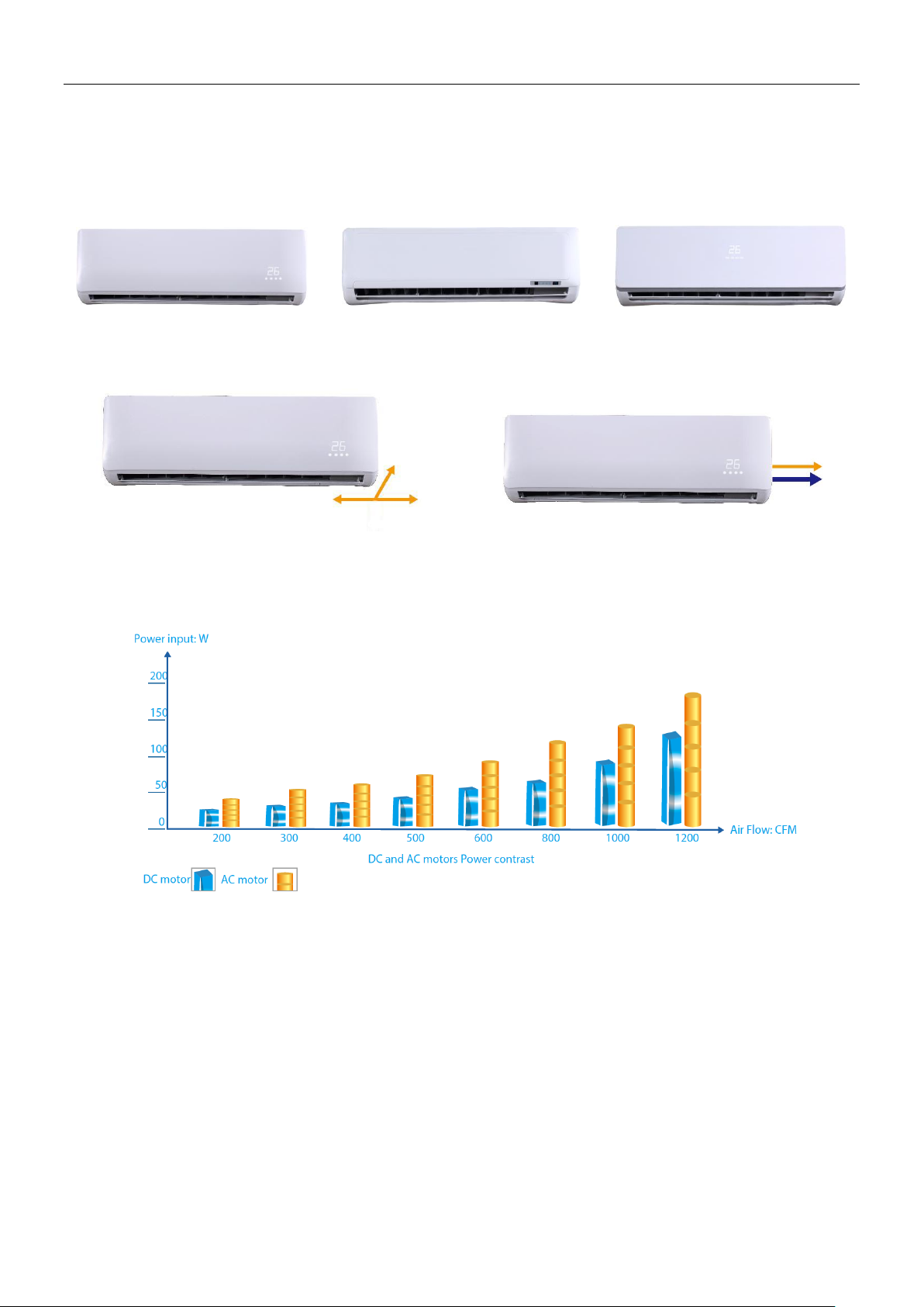
Various selection
Three styles of panels to choose.
M9 panel (standard)
M3 panel
M10 panel
Flexible installation
Multi-refrigerant outlet pipe method: left\right\rear, more flexible for installation.
Flexsible piping connection
Refrigerant piping and condensate piping on the same side
High efficiency DC fan motor
The power consumption of DC driven VRF indoor units can be reduced up to 30% in comparison to
corresponding AC type.
Quiet operation
Adoption of the 2000 stages element positioning mechanical expansion valve, ensures precise flow control, as
well as lower modulation noise when EXV operating.
More smooth airflow with less turbulence. Owing to the multiple-blade fan and the air guide design, the airflow
is getting smoother and more comfortable.

MCAC-VTSM-2016-05 Wall Mounted M Series
3
2. Specifications
Model
MI-22G/DHN1-M
MI-28G/DHN1-M
MI-36G/DHN1-M
MI-45G/DHN1-M
Power supply
V- Ph-Hz
220-240V~50Hz
Cooling
Capacity
kW
2.2
2.8
3.6
4.5
Input
W
8
9
19
19
Rated current
A
0.27
0.31
0.43
0.44
Heating
Capacity
kW
2.4
3.2
4
5
Input
W
8
9
19
19
Rated current
A
0.27
0.31
0.43
0.44
Indoor fan motor
Model
WZDK20-38G
WZDK20-38G
ZKSP-58-8-1
ZKSP-58-8-1
Type
DC motor
Input
W
7
8
18
18
Indoor coil
Number of rows
1
2
1
2
Tube pitch× row
pitch
mm
21×13.37
Fin spacing
mm
1.3
Fin type
Hydrophilic aluminum
Piping diameter
mm
Ф7
Length× height
mm
585×315
585×315
701×315
701×315
Number of circuits
2
3
3
5
Indoor air flow (H/M/L)
m
3
/h
422/393/356
417/370/316
656/573/488
594/507/424
Indoor noise level (H/M/L)
dB(A)
31/30/29
31/30/29
33/32/30
35/33/31
Indoor unit
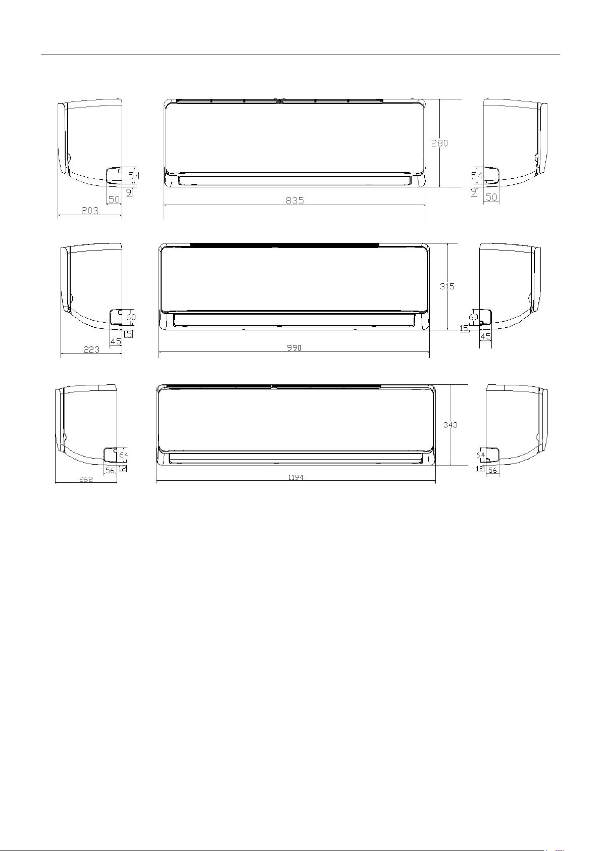
Dimension (W×H×D)
mm
835×280×203
835×280×203
990×315×223
990×315×223
Packing (W×H×D)
mm
935×385×320
935×385×320
1085×420×335
1085×420×335
Net/Gross weight
kg
8.4/12.1
9.5/13.1
11.4/15.5
12.8/16.9
Refrigerant type
R410A
Throttle
Type
Electronic expansion valve
Design pressure (H/L)
MPa
4.4/2.6
Liquid pipe/ Gas pipe
mm
Ф6.35/ Ф12.7
Connecting wiring
Power wiring
mm
2
3×2.5
Signal wiring
mm
2
3×0.75
Drainage water pipe diameter
mm
Ф16.5
Controller
Wireless remote controller
Notes:
Nominal cooling capacities are based on the following conditions: return air temperature: 27°CDB, 19°CWB; outdoor temperature: 35°CDB,
equivalent ref. piping: 8m (horizontal)
Nominal heating capacities are based on the following conditions: return air temperature: 20°CDB, outdoor temperature: 7°CDB, 6°CWB;
equivalent ref. piping: 8m (horizontal)

Wall Mounted M Series MCAC-VTSM-2016-05
4
Specifications
Model
MI-56G/DHN1-M
MI-71G/DHN1-M
MI-80G/DHN1-M
MI-90G/DHN1-M
Power supply
V- Ph-Hz
220-240V~50Hz
Cooling
Capacity
kW
5.6
7.1
8
9
Input
W
27
49
53
82
Rated current
A
0.58
0.6
0.6
0.78
Heating
Capacity
kW
6.3
8
9
10
Input
W
27
49
53
80
Rated current
A
0.58
0.6
0.6
0.78
Indoor fan motor
Model
ZKSP-58-8-1
ZKSP-60-8-3
ZKSP-60-8-3
ZKSP-60-8-3
Type
DC motor
Input
W
25
40
40
65
Indoor coil
Number of rows
2
2
2
2
Tube pitch× row
pitch
mm
21×13.37
Fin spacing
mm
1.3
Fin type
Hydrophilic aluminum
Piping diameter
mm
Ф7
Length× height
mm
701×315
825×399
825×399
825×399
Number of circuits
5
Indoor air flow (H/M/L)
m
3
/h
747/648/547
1195/1005/809
1195/1005/809
1421/1067/867
Indoor noise level (H/M/L)
dB(A)
38/36/34
44/39/36
44/39/36
48/43/38
Indoor unit
Dimension (W×H×D)
mm
990×315×223
1194×343×262
1194×343×262
1194×343×262
Packing (W×H×D)
mm
1085×420×335
1290×375×460
1290×375×460
1290×375×460
Net/Gross weight
kg
12.8/16.9
17/22.4
17/22.4
17/22.4
Refrigerant type
R410A
Throttle
Type
Electronic expansion valve
Design pressure (H/L)
MPa
4.4/2.6
Liquid pipe/ Gas pipe
mm
Ф9.53/ Ф15.9
Connecting wiring
Power wiring
mm
2
3×2.5
Signal wiring
mm
2
3×0.75
Drainage water pipe diameter
mm
Ф16.5
Controller
Wireless remote controller
Notes:
Nominal cooling capacities are based on the following conditions: return air temperature: 27°CDB, 19°CWB; outdoor temperature: 35°CDB,
equivalent ref. piping: 8m (horizontal)
Nominal heating capacities are based on the following conditions: return air temperature: 20°CDB, outdoor temperature: 7°CDB, 6°CWB;
equivalent ref. piping: 8m (horizontal)
MCAC-VTSM-2016-05 Wall Mounted M Series
5
3. Dimensions
MI-22G/DHN1-M, MI-28G/DHN1-M
MI-36G/DHN1-M, MI-45G/DHN1-M, MI-56G/DHN1-M
MI-71G/DHN1-M, MI-80G/DHN1-M, MI-90G/DHN1-M
Wall Mounted M Series MCAC-VTSM-2016-05
6
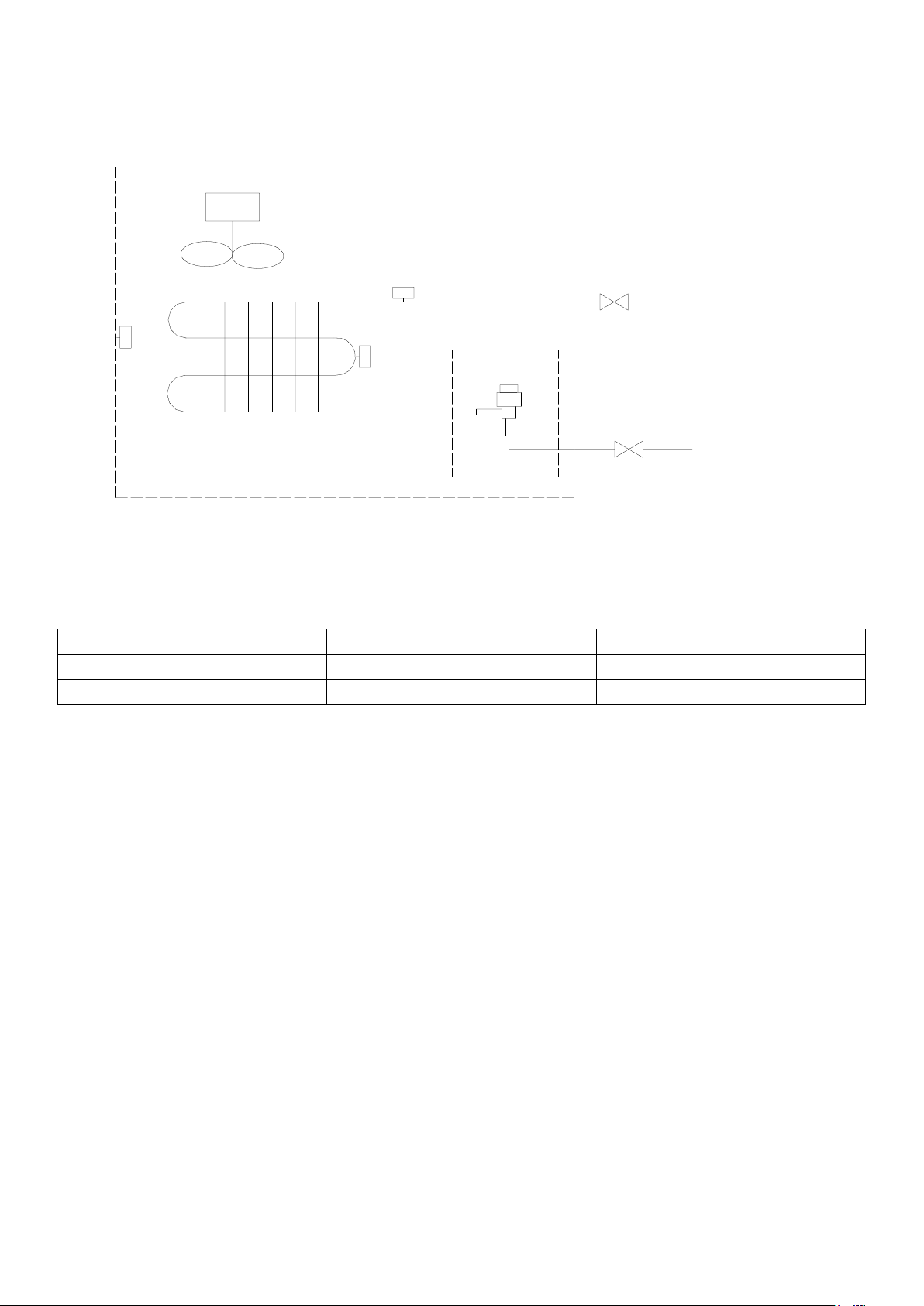
4. Piping Diagrams
flare nut
flare nut
T2B
gas side
motor
heat exchanger
fan
EXV
liquid side
T2
T1
T1: Indoor ambient temperature sensor;
T2: Temperature sensor in the middle of evaporator;
T2B: Evaporator outlet temperature sensor.
Refrigerant pipe connection port diameters
Model
Gas pipe
Liquid pipe
2.2-4.5kW
Φ12.7
Φ6.35
5.6-9.0kW
Φ15.9
Φ9.53
MCAC-VTSM-2016-05 Wall Mounted M Series
7
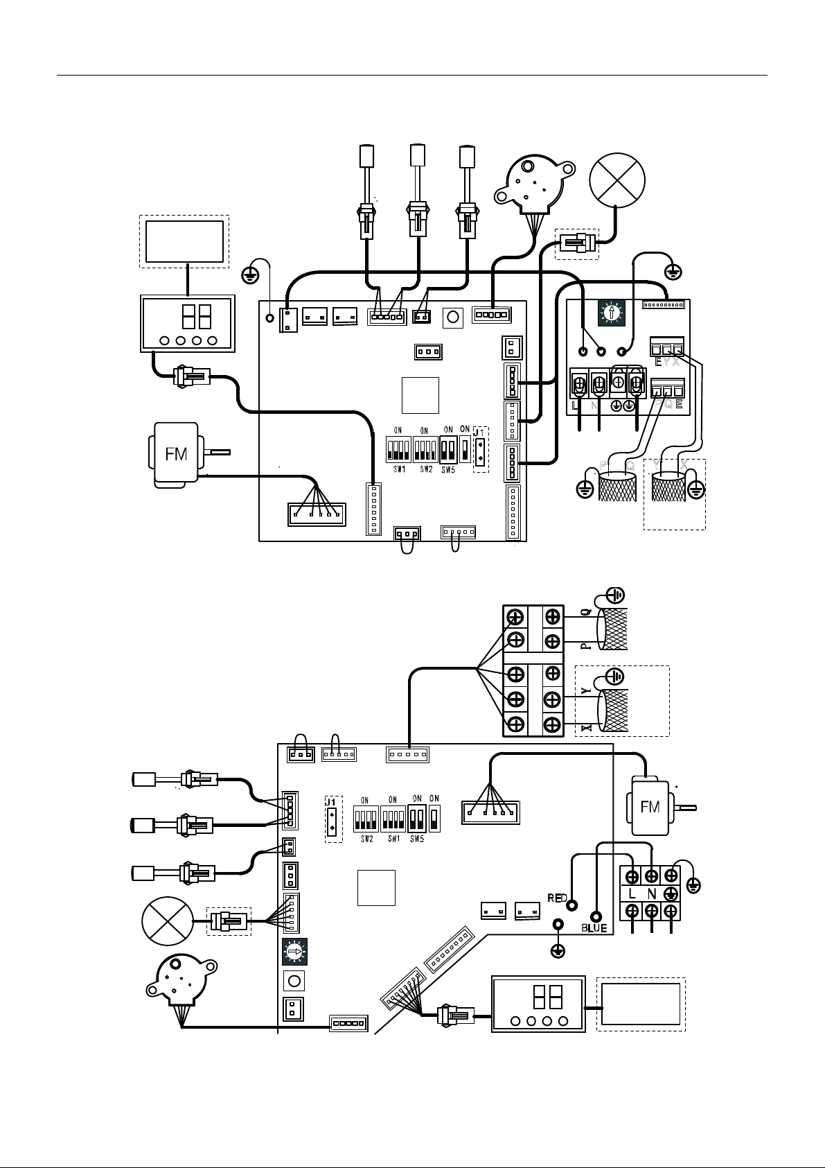
5. Wiring Diagrams
MI-22G/DHN1-M, MI-28G/DHN1-M
MI-36G/DHN1-M, MI-45G/DHN1-M, MI-56G/DHN1-M
ENC1
POWER
CN12
CN5
PMV
GM
To outdoor
COMM. BUS
New display panel
Wire
controller
maincontrolBoard
CN17
CN19
CN22
XS4
XP4
BLUE
T1
XS3 XP3
WHITE
Y/G
CN6
SW6
CN15
CN9
CN24CN 11
CN8
CN10
CN4
SW3
CN2
CN3
CN18
CN1
L N
T2
BLACK
XS2
XP2
T2B
XS1
XP1
CN20
P Q E
EY X
CN21
P Q
Y X
To C C M
COM M. BU
S
CN16
POW ER I N
XS5XP5
CN2CN3
CN15
CN12
CN6
SW3
CN9
SW6
CN19
ENC1
POWER
XT2
P
Q
(
E
)
X
Y
POWER IN
Y/G
XT1
New di splay panel
XS4
XP4
Wire
controller
CN5
CN10
CN4
PMV
GM
T2
T1
T2B
XP3
XS3
XP1
XS1
BLUE
WHITE
XS2
XP2
BLACK
CN11
CN16
CN17
CN18
GRAY
YELLOW
BLUE
WHITE
To outdoor
COMM. BUS
To CCM
COMM. BUS
Y/G
BLACK
XS5
XP5
maincontrolBoard
Wall Mounted M Series MCAC-VTSM-2016-05
8
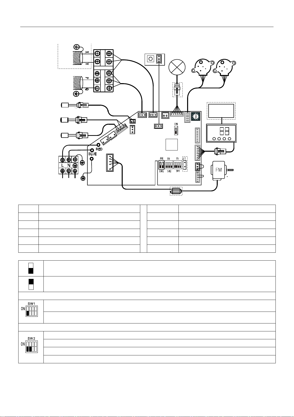
Wiring diagrams
MI-71G/DHN1-M, MI-80G/DHN1-M, MI-90G/DHN1-M
Code definition
Code Name Code Name
FM Fan motor T2B Evaporator outlet temperature sensor
GM Swing motor CS Water level switch
PMV EXV XP1-5/XS1-5 Connectors
T1 Indoor ambient temperature sensor XT1/XT2 Terminals
T2 Temperature sensor in the middle of evaporator MR Magnetic ring
Dial switch setting
Means 0
Means 1
SW1 setting
0 means auto addressing mode (Default)
1 means factory test mod
SW2 setting
00 means when temperature is 15°C or below, fan will stop to prevent cold air(Default)
01 means when temperature is 20°C or below, fan will stop to prevent cold air
10 means when temperature is 24°C or below, fan will stop to prevent cold air
11 means when temperature is 26°C or below, fan will stop to prevent cold air
C
N
2
C
N
3
CN4
CN11
CN17
CN5
CN9
CN15
CN12
ENC1
POWER
CN10
CN6
CN7
CN16
CN8
C
N
1
8
POWER IN
Y/G
XT1
T2
T1
T2B
XP3
XS3
XP1
XS1
BLUE
WHITE
XS2
XP2
BLACK
XT2
PQ
(E)
XY
GRAY
YELLOW
BLUE
WHITE
T o ou tdo or
COMM. BUS
To CCM
COMM. BUS
GM
PMV
Wire
controller
GM
SW3
CN1
CN19
XS4
XP4
Y/G
SW6
BLACK
BLACK
MR
XS5
XP5
maincontrolBoard
O
N
ON
1234
1234

MCAC-VTSM-2016-05 Wall Mounted M Series
9
Dial switch setting
SW2 setting
00 means in heating mode, the fan which stop for reaching the set temp., will periodically stop for 4 minutes and run
for 1 minute (Default)
01 means in heating mode, the fan which stop for reaching the set temp., will periodically stop for 8 minutes and run
for 1 minute
10 means in heating mode, the fan which stop for reaching the set temp., will periodically stop for 12 minutes and
run for 1 minute
11 means in heating mode, the fan which stop for reaching the set temp., will periodically stop for 16 minutes and
run for 1 minute
SW5 setting
00 means temperature compensation value is 6
o
C in heating mode (default)
01 means temperature compensation value is 2
o
C in heating mode
10 means temperature compensation value is 4
o
C in heating mode
11 means temperature compensation value is 8
o
C in heating mode
SW6 setting
0 means temperature compensation value is 0
o
C in cooling mode (default)
1 means temperature compensation value is 2
o
C in cooling mode
J1 definition
With auto restart function
Non-auto restart function
1234
12
SW5
ON
SW6
ON
Wall Mounted M Series MCAC-VTSM-2017-02
10
6. Capacity Tables
6.1 Cooling capacity tables
TC: Total Capacity; SC: Sensible Capacity
Indoor
Unit size
(kW)
Outdoor
temperature
(℃DB)
Indoor temperature (℃WB/DB)
14/20
16/23
18/26
19/27
20/28
22/30
24/32
TC
SC
TC
SC
TC
SC
TC
SC
TC
SC
TC
SC
TC
SC
kW
kW
kW
kW
kW
kW
kW
kW
kW
kW
kW
kW
kW
kW
2.2
10.0
1.5
1.3
1.8
1.4
2.1
1.5
2.2
1.5
2.3
1.6
2.6
1.6
2.9
1.5
12.0
1.5
1.3
1.8
1.4
2.1
1.5
2.2
1.5
2.3
1.6
2.6
1.6
2.8
1.5
14.0
1.5
1.3
1.8
1.4
2.1
1.5
2.2
1.5
2.3
1.6
2.6
1.6
2.8
1.5
16.0
1.5
1.3
1.8
1.4
2.1
1.5
2.2
1.5
2.3
1.6
2.6
1.6
2.8
1.5
18.0
1.5
1.3
1.8
1.4
2.1
1.5
2.2
1.5
2.3
1.6
2.6
1.6
2.8
1.4
20.0
1.5
1.3
1.8
1.4
2.1
1.5
2.2
1.5
2.3
1.6
2.6
1.6
2.7
1.4
21.0
1.5
1.3
1.8
1.4
2.1
1.5
2.2
1.5
2.3
1.6
2.6
1.6
2.7
1.4
23.0
1.5
1.3
1.8
1.4
2.1
1.5
2.2
1.5
2.3
1.6
2.5
1.5
2.7
1.4
25.0
1.5
1.3
1.8
1.4
2.1
1.5
2.2
1.5
2.3
1.6
2.5
1.5
2.6
1.4
27.0
1.5
1.3
1.8
1.4
2.1
1.5
2.2
1.5
2.3
1.6
2.5
1.5
2.6
1.4
29.0
1.5
1.3
1.8
1.4
2.1
1.5
2.2
1.5
2.3
1.6
2.4
1.4
2.5
1.4
31.0
1.5
1.3
1.8
1.4
2.1
1.5
2.2
1.5
2.3
1.6
2.4
1.4
2.5
1.4
33.0
1.5
1.3
1.8
1.4
2.1
1.5
2.2
1.5
2.3
1.6
2.4
1.4
2.4
1.4
35.0
1.5
1.3
1.8
1.4
2.1
1.5
2.2
1.5
2.3
1.6
2.3
1.3
2.4
1.4
37.0
1.5
1.3
1.8
1.4
2.1
1.5
2.2
1.5
2.3
1.6
2.3
1.3
2.3
1.4
39.0
1.5
1.3
1.8
1.4
2.1
1.5
2.2
1.5
2.2
1.5
2.3
1.3
2.3
1.4
42.0
1.5
1.3
1.8
1.4
2.1
1.5
2.2
1.5
2.2
1.5
2.3
1.3
2.3
1.4
44.0
1.5
1.3
1.8
1.4
2.1
1.5
2.2
1.5
2.2
1.5
2.3
1.3
2.3
1.4
46.0
1.5
1.3
1.8
1.4
2.1
1.5
2.2
1.5
2.2
1.5
2.3
1.3
2.3
1.4
2.8
10.0
1.9
1.6
2.3
1.8
2.6
1.9
2.8
1.9
3.0
1.9
3.3
2.0
3.7
2.0
12.0
1.9
1.6
2.3
1.8
2.6
1.9
2.8
1.9
3.0
1.9
3.3
2.0
3.6
2.0
14.0
1.9
1.6
2.3
1.8
2.6
1.9
2.8
1.9
3.0
1.9
3.3
2.0
3.6
2.0
16.0
1.9
1.6
2.3
1.8
2.6
1.9
2.8
1.9
3.0
1.9
3.3
2.0
3.5
1.9
18.0
1.9
1.6
2.3
1.8
2.6
1.9
2.8
1.9
3.0
1.9
3.3
2.0
3.5
1.9
20.0
1.9
1.6
2.3
1.8
2.6
1.9
2.8
1.9
3.0
1.9
3.3
2.0
3.4
1.9
21.0
1.9
1.6
2.3
1.8
2.6
1.9
2.8
1.9
3.0
1.9
3.3
2.0
3.4
1.9
23.0
1.9
1.6
2.3
1.8
2.6
1.9
2.8
1.9
3.0
1.9
3.3
2.0
3.4
1.9
25.0
1.9
1.6
2.3
1.8
2.6
1.9
2.8
1.9
3.0
1.9
3.2
1.9
3.3
1.9
27.0
1.9
1.6
2.3
1.8
2.6
1.9
2.8
1.9
3.0
1.9
3.2
1.9
3.3
1.9
29.0
1.9
1.6
2.3
1.8
2.6
1.9
2.8
1.9
3.0
1.9
3.1
1.8
3.2
1.8
31.0
1.9
1.6
2.3
1.8
2.6
1.9
2.8
1.9
3.0
1.9
3.1
1.8
3.2
1.7
33.0
1.9
1.6
2.3
1.8
2.6
1.9
2.8
1.9
3.0
1.9
3.1
1.8
3.1
1.7
35.0
1.9
1.6
2.3
1.8
2.6
1.9
2.8
1.9
2.9
1.9
3.0
1.8
3.1
1.7
37.0
1.9
1.6
2.3
1.8
2.6
1.9
2.8
1.9
2.9
1.9
3.0
1.8
3.0
1.7
39.0
1.9
1.6
2.3
1.8
2.6
1.9
2.8
1.9
2.9
1.9
3.0
1.9
3.0
1.7
42.0
1.9
1.6
2.3
1.8
2.6
1.9
2.8
1.9
2.9
1.9
3.0
1.9
3.0
1.7
44.0
1.9
1.6
2.3
1.8
2.6
1.9
2.8
1.9
2.9
1.9
3.0
1.9
3.0
1.7
46.0
1.9
1.6
2.3
1.8
2.6
1.9
2.8
1.9
2.9
1.9
3.0
1.9
3.0
1.7
3.6
10.0
2.5
1.9
2.9
2.1
3.4
2.3
3.6
2.4
3.8
2.5
4.3
2.4
4.7
2.5
12.0
2.5
1.9
2.9
2.1
3.4
2.3
3.6
2.4
3.8
2.5
4.3
2.4
4.7
2.5
14.0
2.5
1.9
2.9
2.1
3.4
2.3
3.6
2.4
3.8
2.5
4.3
2.4
4.6
2.4
16.0
2.5
1.9
2.9
2.1
3.4
2.3
3.6
2.4
3.8
2.5
4.3
2.4
4.5
2.4
18.0
2.5
1.9
2.9
2.1
3.4
2.3
3.6
2.4
3.8
2.5
4.3
2.4
4.5
2.4
20.0
2.5
1.9
2.9
2.1
3.4
2.3
3.6
2.4
3.8
2.5
4.3
2.4
4.4
2.3
21.0
2.5
1.9
2.9
2.1
3.4
2.3
3.6
2.4
3.8
2.5
4.3
2.4
4.4
2.3
23.0
2.5
1.9
2.9
2.1
3.4
2.3
3.6
2.4
3.8
2.5
4.1
2.3
4.3
2.2
25.0
2.5
1.9
2.9
2.1
3.4
2.3
3.6
2.4
3.8
2.5
4.1
2.3
4.2
2.2
27.0
2.5
1.9
2.9
2.1
3.4
2.3
3.6
2.4
3.8
2.5
4.0
2.2
4.2
2.2
29.0
2.5
1.9
2.9
2.1
3.4
2.3
3.6
2.4
3.8
2.5
4.0
2.2
4.1
2.2
31.0
2.5
1.9
2.9
2.1
3.4
2.3
3.6
2.4
3.8
2.5
4.2
2.6
4.1
2.2
33.0
2.5
1.9
2.9
2.1
3.4
2.3
3.6
2.4
3.8
2.5
4.2
2.6
3.9
2.1
35.0
2.5
1.9
2.9
2.1
3.4
2.3
3.6
2.4
3.8
2.5
4.2
2.6
3.9
2.1
37.0
2.5
1.9
2.9
2.1
3.4
2.3
3.6
2.4
3.7
2.4
3.8
2.3
3.9
2.1
39.0
2.5
1.9
2.9
2.1
3.4
2.3
3.6
2.4
3.7
2.4
3.8
2.3
3.8
2.1
42.0
2.5
1.9
2.9
2.1
3.4
2.3
3.6
2.4
3.7
2.4
3.8
2.3
3.8
2.1
44.0
2.5
1.9
2.9
2.1
3.4
2.3
3.6
2.4
3.7
2.4
3.8
2.3
3.8
2.1
46.0
2.5
1.9
2.9
2.1
3.4
2.3
3.6
2.4
3.7
2.4
3.8
2.3
3.8
2.1
MCAC-VTSM-2017-02 Wall Mounted M Series
11
Cooling capacity tables
TC: Total Capacity; SC: Sensible Capacity
Indoor
Unit size
(kW)
Outdoor
temperature
(℃DB)
Indoor temperature (℃WB/DB)
14/20
16/23
18/26
19/27
20/28
22/30
24/32
TC
SC
TC
SC
TC
SC
TC
SC
TC
SC
TC
SC
TC
SC
kW
kW
kW
kW
kW
kW
kW
kW
kW
kW
kW
kW
kW
kW
4.5
10.0
3.1
2.4
3.7
2.6
4.2
2.8
4.5
2.9
4.8
3.0
5.3
3.4
5.9
3.0
12.0
3.1
2.4
3.7
2.6
4.2
2.8
4.5
2.9
4.8
3.0
5.3
3.4
5.9
3.0
14.0
3.1
2.4
3.7
2.6
4.2
2.8
4.5
2.9
4.8
3.0
5.3
3.4
5.8
3.0
16.0
3.1
2.4
3.7
2.6
4.2
2.8
4.5
2.9
4.8
3.0
5.3
3.4
5.6
2.9
18.0
3.1
2.4
3.7
2.6
4.2
2.8
4.5
2.9
4.8
3.0
5.3
3.4
5.7
3.0
20.0
3.1
2.4
3.7
2.6
4.2
2.8
4.5
2.9
4.8
3.0
5.3
3.4
5.7
3.0
21.0
3.1
2.4
3.7
2.6
4.2
2.8
4.5
2.9
4.8
3.0
5.3
3.4
5.6
3.0
23.0
3.1
2.4
3.7
2.6
4.2
2.8
4.5
2.9
4.8
3.0
5.3
3.4
5.5
3.0
25.0
3.1
2.4
3.7
2.6
4.2
2.8
4.5
2.9
4.8
3.0
5.2
3.0
5.4
2.9
27.0
3.1
2.4
3.7
2.6
4.2
2.8
4.5
2.9
4.8
3.0
5.1
3.0
5.2
2.8
29.0
3.1
2.4
3.7
2.6
4.2
2.8
4.5
2.9
4.8
3.0
5.1
2.9
5.2
2.8
31.0
3.1
2.4
3.7
2.6
4.2
2.8
4.5
2.9
4.8
3.0
5.0
2.9
5.1
2.7
33.0
3.1
2.4
3.7
2.6
4.2
2.8
4.5
2.9
4.8
3.0
4.9
2.8
5.1
2.7
35.0
3.1
2.4
3.7
2.6
4.2
2.8
4.5
2.9
4.8
3.0
4.8
2.8
5.0
2.7
37.0
3.1
2.4
3.7
2.6
4.2
2.8
4.5
2.9
4.8
3.0
4.8
2.9
4.9
2.6
39.0
3.1
2.4
3.7
2.6
4.2
2.8
4.5
2.9
4.6
2.8
4.7
2.8
4.8
2.6
42.0
3.1
2.4
3.7
2.6
4.2
2.8
4.5
2.9
4.6
2.8
4.7
2.8
4.8
2.6
44.0
3.1
2.4
3.7
2.6
4.2
2.8
4.5
2.9
4.6
2.8
4.7
2.8
4.8
2.6
46.0
3.1
2.4
3.7
2.6
4.2
2.8
4.5
2.9
4.6
2.8
4.7
3.1
4.8
2.6
5.6
10.0
3.9
2.7
4.6
3.0
5.3
3.3
5.6
3.4
5.9
3.5
6.6
3.6
7.3
3.5
12.0
3.9
2.7
4.6
3.0
5.3
3.3
5.6
3.4
5.9
3.5
6.6
3.6
7.2
3.5
14.0
3.9
2.7
4.6
3.0
5.3
3.3
5.6
3.4
5.9
3.5
6.6
3.6
7.1
3.5
16.0
3.9
2.7
4.6
3.0
5.3
3.3
5.6
3.4
5.9
3.5
6.6
3.6
7.0
3.4
18.0
3.9
2.7
4.6
3.0
5.3
3.3
5.6
3.4
5.9
3.5
6.6
3.6
6.8
3.4
20.0
3.9
2.7
4.6
3.0
5.3
3.3
5.6
3.4
5.9
3.5
6.6
3.6
6.7
3.3
21.0
3.9
2.7
4.6
3.0
5.3
3.3
5.6
3.4
5.9
3.5
6.6
3.6
6.6
3.3
23.0
3.9
2.7
4.6
3.0
5.3
3.3
5.6
3.4
5.9
3.5
6.6
3.6
6.6
3.3
25.0
3.9
2.7
4.6
3.0
5.3
3.3
5.6
3.4
5.9
3.5
6.6
3.6
6.5
3.2
27.0
3.9
2.7
4.6
3.0
5.3
3.3
5.6
3.4
5.9
3.5
6.4
3.5
6.4
3.2
29.0
3.9
2.7
4.6
3.0
5.3
3.3
5.6
3.4
5.9
3.5
6.3
3.5
6.4
3.3
31.0
3.9
2.7
4.6
3.0
5.3
3.3
5.6
3.4
5.9
3.5
6.2
3.4
6.2
3.2
33.0
3.9
2.7
4.6
3.0
5.3
3.3
5.6
3.4
5.9
3.5
6.2
3.4
6.2
3.2
35.0
3.9
2.7
4.6
3.0
5.3
3.3
5.6
3.4
5.9
3.5
6.0
3.3
6.0
3.1
37.0
3.9
2.7
4.6
3.0
5.3
3.3
5.6
3.4
5.9
3.5
5.9
3.2
6.0
3.1
39.0
3.9
2.7
4.6
3.0
5.3
3.3
5.6
3.4
5.7
3.4
5.8
3.2
6.0
3.1
42.0
3.9
2.7
4.6
3.0
5.3
3.3
5.6
3.4
5.7
3.4
5.8
3.2
6.0
3.1
44.0
3.9
2.7
4.6
3.0
5.3
3.3
5.6
3.4
5.7
3.4
5.8
3.2
6.0
3.1
46.0
3.9
2.7
4.6
3.0
5.3
3.3
5.6
3.4
5.7
3.7
5.8
3.2
6.0
3.1
7.1
10.0
4.9
3.6
5.8
4.0
6.7
4.3
7.1
4.5
7.5
4.4
8.4
4.5
9.2
4.6
12.0
4.9
3.6
5.8
4.0
6.7
4.3
7.1
4.5
7.5
4.4
8.4
4.5
9.1
4.5
14.0
4.9
3.6
5.8
4.0
6.7
4.3
7.1
4.5
7.5
4.4
8.4
4.5
9.0
4.5
16.0
4.9
3.6
5.8
4.0
6.7
4.3
7.1
4.5
7.5
4.4
8.4
4.5
8.9
4.4
18.0
4.9
3.6
5.8
4.0
6.7
4.3
7.1
4.5
7.5
4.4
8.4
4.5
8.7
4.3
20.0
4.9
3.6
5.8
4.0
6.7
4.3
7.1
4.5
7.5
4.4
8.4
4.5
8.5
4.2
21.0
4.9
3.6
5.8
4.0
6.7
4.3
7.1
4.5
7.5
4.4
8.4
4.5
8.4
4.2
23.0
4.9
3.6
5.8
4.0
6.7
4.3
7.1
4.5
7.5
4.4
8.4
4.5
8.3
4.1
25.0
4.9
3.6
5.8
4.0
6.7
4.3
7.1
4.5
7.5
4.4
8.4
4.5
8.2
4.1
27.0
4.9
3.6
5.8
4.0
6.7
4.3
7.1
4.5
7.5
4.4
8.1
4.3
8.2
4.1
29.0
4.9
3.6
5.8
4.0
6.7
4.3
7.1
4.5
7.5
4.5
8.0
4.3
8.1
4.1
31.0
4.9
3.6
5.8
4.0
6.7
4.3
7.1
4.5
7.5
4.5
7.9
4.3
7.8
4.0
33.0
4.9
3.6
5.8
4.0
6.7
4.3
7.1
4.5
7.5
4.5
7.8
4.2
7.8
4.0
35.0
4.9
3.6
5.8
4.0
6.7
4.3
7.1
4.5
7.5
4.5
7.6
4.1
7.7
3.9
37.0
4.9
3.6
5.8
4.0
6.7
4.3
7.1
4.5
7.4
4.4
7.5
4.1
7.6
4.0
39.0
4.9
3.6
5.8
4.0
6.7
4.3
7.1
4.5
7.2
4.3
7.4
4.1
7.6
4.0
42.0
4.9
3.6
5.8
4.0
6.7
4.3
7.1
4.5
7.2
4.3
7.4
4.1
7.6
4.0
44.0
4.9
3.6
5.8
4.0
6.7
4.3
7.1
4.5
7.2
4.3
7.4
4.1
7.6
4.0
46.0
4.9
3.6
5.8
4.0
6.7
4.3
7.1
4.5
7.2
4.3
7.4
4.1
7.6
4.0
Wall Mounted M Series MCAC-VTSM-2017-02
12
Indoor
Unit size
(kW)
Outdoor
temperature
(℃DB)
Indoor temperature (℃WB/DB)
14/20
16/23
18/26
19/27
20/28
22/30
24/32
TC
SC
TC
SC
TC
SC
TC
SC
TC
SC
TC
SC
TC
SC
kW
kW
kW
kW
kW
kW
kW
kW
kW
kW
kW
kW
kW
kW
8.0
10.0
5.5
6.4
6.6
5.9
7.5
5.6
8.0
5.5
8.4
5.1
9.4
4.6
10.4
4.3
12.0
5.5
6.4
6.6
5.9
7.5
5.6
8.0
5.5
8.4
5.1
9.4
4.6
10.2
4.3
14.0
5.5
6.4
6.6
5.9
7.5
5.6
8.0
5.5
8.4
5.1
9.4
4.6
10.2
4.3
16.0
5.5
6.4
6.6
5.9
7.5
5.6
8.0
5.5
8.4
5.1
9.4
4.6
10.0
4.3
18.0
5.5
6.4
6.6
5.9
7.5
5.6
8.0
5.5
8.4
5.1
9.4
4.6
9.8
4.3
20.0
5.5
6.4
6.6
5.9
7.5
5.6
8.0
5.5
8.4
5.1
9.4
4.6
9.6
4.3
21.0
5.5
6.4
6.6
5.9
7.5
5.6
8.0
5.5
8.4
5.1
9.4
4.6
9.4
4.3
23.0
5.5
6.4
6.6
5.9
7.5
5.6
8.0
5.5
8.4
5.1
9.4
4.6
9.4
4.3
25.0
5.5
6.4
6.6
5.9
7.5
5.6
8.0
5.5
8.4
5.1
9.4
4.6
9.3
4.3
27.0
5.5
6.4
6.6
5.9
7.5
5.6
8.0
5.5
8.4
5.1
9.1
4.6
9.2
4.4
29.0
5.5
6.4
6.6
5.9
7.5
5.6
8.0
5.5
8.4
5.2
9.0
4.7
9.1
4.4
31.0
5.5
6.4
6.6
5.9
7.5
5.6
8.0
5.5
8.4
5.2
8.9
4.7
8.8
4.4
33.0
5.5
6.4
6.6
5.9
7.5
5.6
8.0
5.5
8.4
5.2
8.8
4.7
8.8
4.4
35.0
5.5
6.4
6.6
5.9
7.5
5.6
8.0
5.5
8.4
5.2
8.6
4.7
8.6
4.4
37.0
5.5
6.4
6.6
5.9
7.5
5.6
8.0
5.5
8.3
5.2
8.4
4.8
8.6
4.6
39.0
5.5
6.4
6.6
5.9
7.5
5.6
8.0
5.5
8.1
5.2
8.3
4.8
8.6
4.6
42.0
5.5
6.4
6.6
5.9
7.5
5.6
8.0
5.5
8.1
5.2
8.3
4.8
8.6
4.6
44.0
5.5
6.4
6.6
5.9
7.5
5.6
8.0
5.5
8.1
5.2
8.3
4.8
8.6
4.6
46.0
5.5
6.4
6.6
5.9
7.5
5.6
8.0
5.5
8.1
5.2
8.3
4.8
8.6
4.6
9.0
10.0
6.2
4.9
7.3
5.3
8.4
5.8
9.0
5.9
9.6
6.0
10.6
6.1
11.7
6.0
12.0
6.2
4.9
7.3
5.3
8.4
5.8
9.0
5.9
9.6
6.0
10.6
6.1
11.5
5.9
14.0
6.2
4.9
7.3
5.3
8.4
5.8
9.0
5.9
9.6
6.0
10.6
6.1
11.4
5.9
16.0
6.2
4.9
7.3
5.3
8.4
5.8
9.0
5.9
9.6
6.0
10.6
6.1
11.3
5.8
18.0
6.2
4.9
7.3
5.3
8.4
5.8
9.0
5.9
9.6
6.0
10.6
6.1
11.0
5.8
20.0
6.2
4.9
7.3
5.3
8.4
5.8
9.0
5.9
9.6
6.0
10.6
6.1
10.8
5.7
21.0
6.2
4.9
7.3
5.3
8.4
5.8
9.0
5.9
9.6
6.0
10.6
6.1
10.6
5.6
23.0
6.2
4.9
7.3
5.3
8.4
5.8
9.0
5.9
9.6
6.0
10.6
6.1
10.5
5.5
25.0
6.2
4.9
7.3
5.3
8.4
5.8
9.0
5.9
9.6
6.0
10.6
6.1
10.4
5.5
27.0
6.2
4.9
7.3
5.3
8.4
5.8
9.0
5.9
9.6
6.0
10.3
5.9
10.4
5.4
29.0
6.2
4.9
7.3
5.3
8.4
5.8
9.0
5.9
9.6
6.0
10.1
5.7
10.3
5.4
31.0
6.2
4.9
7.3
5.3
8.4
5.8
9.0
5.9
9.6
6.0
10.0
5.7
9.9
5.3
33.0
6.2
4.9
7.3
5.3
8.4
5.8
9.0
5.9
9.6
6.0
9.9
5.6
9.9
5.3
35.0
6.2
4.9
7.3
5.3
8.4
5.8
9.0
5.9
9.5
6.0
9.6
5.5
9.7
5.3
37.0
6.2
4.9
7.3
5.3
8.4
5.8
9.0
5.9
9.3
5.8
9.5
5.4
9.6
5.3
39.0
6.2
4.9
7.3
5.3
8.4
5.8
9.0
5.9
9.2
5.7
9.4
5.3
9.6
5.3
42.0
6.2
4.9
7.3
5.3
8.4
5.8
9.0
5.9
9.2
5.7
9.4
5.3
9.6
5.3
44.0
6.2
4.9
7.3
5.3
8.4
5.8
9.0
5.9
9.2
5.7
9.4
5.3
9.6
5.3
46.0
6.2
4.9
7.3
5.3
8.4
5.8
9.0
5.9
9.2
5.7
9.4
5.3
9.6
5.3
MCAC-VTSM-2017-02 Wall Mounted M Series
13
6.2 Heating capacity tables
TC: Total Capacity; WB: Wet-bulb temperature; DB: Dry-bulb temperature
Indoor
Unit size
(kW)
Outdoor
temperature
(℃)
Indoor temperature (℃ DB)
16.00
18.00
20.00
21.00
22.00
24.00
TC
TC
TC
TC
TC
TC
WB
DB
kW
kW
kW
kW
kW
kW
2.2
-20
-19.8
1.34
1.34
1.34
1.34
1.34
1.34
-19
-18.8
1.44
1.44
1.44
1.44
1.44
1.44
-17
-16.7
1.51
1.51
1.51
1.51
1.51
1.51
-15
-14.7
1.56
1.56
1.56
1.56
1.56
1.56
-13.00
-12.60
1.66
1.66
1.66
1.66
1.66
1.66
-11.00
-10.50
1.68
1.70
1.70
1.70
1.70
1.70
-10.00
-9.50
1.75
1.75
1.75
1.75
1.75
1.75
-9.10
-8.50
1.80
1.80
1.80
1.80
1.80
1.80
-7.60
-7.00
1.82
1.82
1.82
1.82
1.82
1.82
-5.60
-5.00
1.90
1.90
1.90
1.90
1.90
1.90
-3.70
-3.00
1.99
1.99
1.99
1.99
1.99
1.99
-0.70
0.00
2.14
2.14
2.14
2.14
2.14
2.02
2.20
3.00
2.26
2.26
2.26
2.26
2.21
2.02
4.10
5.00
2.33
2.33
2.33
2.33
2.21
2.02
6.00
7.00
2.40
2.40
2.40
2.33
2.21
2.02
7.90
9.00
2.47
2.47
2.40
2.33
2.21
2.02
9.80
11.00
2.54
2.54
2.40
2.33
2.21
2.02
11.80
13.00
2.64
2.59
2.40
2.33
2.21
2.02
13.70
15.00
2.71
2.59
2.40
2.33
2.21
2.02
2.8
-20
-19.8
1.79
1.79
1.79
1.79
1.79
1.79
-19
-18.8
1.92
1.92
1.92
1.92
1.92
1.92
-17
-16.7
2.02
2.02
2.02
2.02
2.02
2.02
-15
-14.7
2.02
2.02
2.02
2.02
2.02
2.02
-13.00
-12.60
2.14
2.14
2.14
2.14
2.14
2.14
-11.00
-10.50
2.24
2.24
2.24
2.24
2.24
2.24
-10.00
-9.50
2.34
2.34
2.34
2.34
2.34
2.34
-9.10
-8.50
2.40
2.40
2.40
2.40
2.40
2.40
-7.60
-7.00
2.43
2.43
2.43
2.43
2.43
2.43
-5.60
-5.00
2.53
2.53
2.53
2.53
2.53
2.53
-3.70
-3.00
2.66
2.66
2.66
2.66
2.66
2.66
-0.70
0.00
2.85
2.85
2.85
2.85
2.85
2.69
2.20
3.00
3.01
3.01
3.01
3.01
2.94
2.69
4.10
5.00
3.10
3.10
3.10
3.10
2.94
2.69
6.00
7.00
3.20
3.20
3.20
3.10
2.94
2.69
7.90
9.00
3.30
3.30
3.20
3.10
2.94
2.69
9.80
11.00
3.39
3.39
3.20
3.10
2.94
2.69
11.80
13.00
3.52
3.46
3.20
3.10
2.94
2.69
13.70
15.00
3.62
3.46
3.20
3.10
2.94
2.69
3.6
-20
-19.8
2.24
2.24
2.24
2.24
2.24
2.24
-19
-18.8
2.40
2.40
2.40
2.40
2.40
2.40
-17
-16.7
2.52
2.52
2.52
2.52
2.52
2.52
-15
-14.7
2.60
2.60
2.60
2.60
2.60
2.60
-13.00
-12.60
2.68
2.68
2.68
2.68
2.68
2.68
-11.00
-10.50
2.80
2.80
2.80
2.80
2.80
2.80
-10.00
-9.50
2.92
2.92
2.92
2.92
2.92
2.92
-9.10
-8.50
3.00
3.00
3.00
3.00
3.00
3.00
-7.60
-7.00
3.04
3.04
3.04
3.04
3.04
3.04
-5.60
-5.00
3.16
3.16
3.16
3.16
3.16
3.16
-3.70
-3.00
3.32
3.32
3.32
3.32
3.32
3.32
-0.70
0.00
3.56
3.56
3.56
3.56
3.56
3.36
2.20
3.00
3.76
3.76
3.76
3.76
3.68
3.36
4.10
5.00
3.88
3.88
3.88
3.88
3.68
3.36
6.00
7.00
4.00
4.00
4.00
3.88
3.68
3.36
7.90
9.00
4.12
4.12
4.00
3.88
3.68
3.36
9.80
11.00
4.24
4.24
4.00
3.88
3.68
3.36
11.80
13.00
4.40
4.32
4.00
3.88
3.68
3.36
13.70
15.00
4.52
4.32
4.00
3.88
3.68
3.36

Wall Mounted M Series MCAC-VTSM-2017-02
14
Heating capacity tables TC: Total Capacity; WB: Wet-bulb temperature; DB: Dry-bulb temperature
Indoor
Unit size
(kW)
Outdoor
temperature
(℃)
Indoor temperature (℃ DB)
16.00
18.00
20.00
21.00
22.00
24.00
TC
TC
TC
TC
TC
TC
WB
DB
kW
kW
kW
kW
kW
kW
4.5
-20
-19.8
2.80
2.80
2.80
2.80
2.80
2.80
-19
-18.8
3.00
3.00
3.00
3.00
3.00
3.00
-20
-19.8
2.80
2.80
2.80
2.80
2.80
2.80
-19
-18.8
3.00
3.00
3.00
3.00
3.00
3.00
-17
-16.7
3.15
3.15
3.15
3.15
3.15
3.15
-15
-14.7
3.25
3.25
3.25
3.25
3.25
3.25
-13.00
-12.60
3.35
3.35
3.35
3.35
3.35
3.35
-11.00
-10.50
3.50
3.50
3.50
3.50
3.50
3.50
-10.00
-9.50
3.65
3.65
3.65
3.65
3.65
3.65
-9.10
-8.50
3.75
3.75
3.75
3.75
3.75
3.75
-7.60
-7.00
3.80
3.80
3.80
3.80
3.80
3.80
-5.60
-5.00
3.95
3.95
3.95
3.95
3.95
3.95
-3.70
-3.00
4.15
4.15
4.15
4.15
4.15
4.15
-0.70
0.00
4.45
4.45
4.45
4.45
4.45
4.20
2.20
3.00
4.70
4.70
4.70
4.70
4.60
4.20
4.10
5.00
4.85
4.85
4.85
4.85
4.60
4.20
6.00
7.00
5.00
5.00
5.00
4.85
4.60
4.20
7.90
9.00
5.15
5.15
5.00
4.85
4.60
4.20
9.80
11.00
5.30
5.30
5.00
4.85
4.60
4.20
11.80
13.00
5.50
5.40
5.00
4.85
4.60
4.20
13.70
15.00
5.65
5.40
5.00
4.85
4.60
4.20
5.6
-20
-19.8
3.53
3.53
3.53
3.53
3.53
3.53
-19
-18.8
3.78
3.78
3.78
3.78
3.78
3.78
-17
-16.7
3.97
3.97
3.97
3.97
3.97
3.97
-15
-14.7
4.10
4.10
4.10
4.10
4.10
4.10
-13.00
-12.60
4.22
4.22
4.22
4.22
4.22
4.22
-11.00
-10.50
4.41
4.41
4.41
4.41
4.41
4.41
-10.00
-9.50
4.60
4.60
4.60
4.60
4.60
4.60
-9.10
-8.50
4.73
4.73
4.73
4.73
4.73
4.73
-7.60
-7.00
4.79
4.79
4.79
4.79
4.79
4.79
-5.60
-5.00
4.98
4.98
4.98
4.98
4.98
4.98
-3.70
-3.00
5.23
5.23
5.23
5.23
5.23
5.23
-0.70
0.00
5.61
5.61
5.61
5.61
5.61
5.29
2.20
3.00
5.92
5.92
5.92
5.92
5.80
5.29
4.10
5.00
6.11
6.11
6.11
6.11
5.80
5.29
6.00
7.00
6.30
6.30
6.30
6.11
5.80
5.29
7.90
9.00
6.49
6.49
6.30
6.11
5.80
5.29
9.80
11.00
6.68
6.68
6.30
6.11
5.80
5.29
11.80
13.00
6.93
6.80
6.30
6.11
5.80
5.29
13.70
15.00
7.12
6.80
6.30
6.11
5.80
5.29
7.1
-20
-19.8
4.48
4.48
4.48
4.48
4.48
4.48
-19
-18.8
4.8
4.8
4.8
4.8
4.8
4.8
-17
-16.7
5.04
5.04
5.04
5.04
5.04
5.04
-15
-14.7
5.2
5.2
5.2
5.2
5.2
5.2
-13.00
-12.60
5.36
5.36
5.36
5.36
5.36
5.36
-11.00
-10.50
5.6
5.6
5.6
5.6
5.6
5.6
-10.00
-9.50
5.84
5.84
5.84
5.84
5.84
5.84
-9.10
-8.50
6
6
6
6
6
6
-7.60
-7.00
6.08
6.08
6.08
6.08
6.08
6.08
-5.60
-5.00
6.32
6.32
6.32
6.32
6.32
6.32
-3.70
-3.00
6.64
6.64
6.64
6.64
6.64
6.64
-0.70
0.00
7.12
7.12
7.12
7.12
7.12
6.72
2.20
3.00
7.52
7.52
7.52
7.52
7.36
6.72
4.10
5.00
7.76
7.76
7.76
7.76
7.36
6.72
6.00
7.00
8
8
8
7.76
7.36
6.72
7.90
9.00
8.24
8.24
8
7.76
7.36
6.72
9.80
11.00
8.48
8.48
8
7.76
7.36
6.72
11.80
13.00
8.8
8.64
8
7.76
7.36
6.72
13.70
15.00
9.04
8.64
8
7.76
7.36
6.72
MCAC-VTSM-2017-02 Wall Mounted M Series
15
Indoor Unit size
(kW)
Outdoor temperature
(℃)
Indoor temperature (℃ DB)
16.00
18.00
20.00
21.00
22.00
24.00
TC
TC
TC
TC
TC
TC
WB
DB
kW
kW
kW
kW
kW
kW
8.0
-20
-19.8
5.04
5.04
5.04
5.04
5.04
5.04
-19
-18.8
5.4
5.4
5.4
5.4
5.4
5.4
-17
-16.7
5.67
5.67
5.67
5.67
5.67
5.67
-15
-14.7
5.85
5.85
5.85
5.85
5.85
5.85
-13.00
-12.60
6.03
6.03
6.03
6.03
6.03
6.03
-11.00
-10.50
6.3
6.3
6.3
6.3
6.3
6.3
-10.00
-9.50
6.57
6.57
6.57
6.57
6.57
6.57
-9.10
-8.50
6.75
6.75
6.75
6.75
6.75
6.75
-7.60
-7.00
6.84
6.84
6.84
6.84
6.84
6.84
-5.60
-5.00
7.11
7.11
7.11
7.11
7.11
7.11
-3.70
-3.00
7.47
7.47
7.47
7.47
7.47
7.47
-0.70
0.00
8.01
8.01
8.01
8.01
8.01
7.56
2.20
3.00
8.46
8.46
8.46
8.46
8.28
7.56
4.10
5.00
8.73
8.73
8.73
8.73
8.28
7.56
6.00
7.00
9
9
9
8.73
8.28
7.56
7.90
9.00
9.27
9.27
9
8.73
8.28
7.56
9.80
11.00
9.54
9.54
9
8.73
8.28
7.56
11.80
13.00
9.9
9.72
9
8.73
8.28
7.56
13.70
15.00
10.17
9.72
9
8.73
8.28
7.56
9.0
-20
-19.8
5.6
5.04
5.6
5.6
5.6
5.6
-19
-18.8
6
5.4
6
6
6
6
-17
-16.7
6.3
6.3
6.3
6.3
6.3
6.3
-15
-14.7
6.5
6.5
6.5
6.5
6.5
6.5
-13.00
-12.60
6.7
6.7
6.7
6.7
6.7
6.7
-11.00
-10.50
7
7
7
7
7
7
-10.00
-9.50
7.3
7.3
7.3
7.3
7.3
7.3
-9.10
-8.50
7.5
7.5
7.5
7.5
7.5
7.5
-7.60
-7.00
7.6
7.6
7.6
7.6
7.6
7.6
-5.60
-5.00
7.9
7.9
7.9
7.9
7.9
7.9
-3.70
-3.00
8.3
8.3
8.3
8.3
8.3
8.3
-0.70
0.00
8.9
8.9
8.9
8.9
8.9
8.4
2.20
3.00
9.4
9.4
9.4
9.4
9.2
8.4
4.10
5.00
9.7
9.7
9.7
9.7
9.2
8.4
6.00
7.00
10
10
10
9.7
9.2
8.4
7.90
9.00
10.3
10.3
10
9.7
9.2
8.4
9.80
11.00
10.6
10.6
10
9.7
9.2
8.4
11.80
13.00
11
10.8
10
9.7
9.2
8.4
13.70
15.00
11.3
10.8
10
9.7
9.2
8.4
 Loading...