

Page 1
CH-9101 Herisau/Switzerland
Internet www.metrohm.com
E-Mail info@metrohm.com
6.6034.013
Metrodata
IC Net 2.1
8.110.8223 Software Manual
11.05.2001 / dö
Page 2

All Rights Reserved.
Printed in Switzerland by Metrohm AG, CH-9101 Herisau 2001
Page 3

Table of contents
Table of contents
1 Introduction
1.1 Purpose of program...................................................................... 1
1.2 Information about the software manual .................................... 1
1.3 Notation and pictograms ............................................................. 3
1.4 Installation...................................................................................... 4
1.4.1 Hardware requirements for the PC................................. 4
1.4.2 Software Installation ....................................................... 4
1.4.3 Software update ............................................................. 5
1.4.4 Software deinstallation ................................................... 6
1.4.5 Demo version ................................................................. 6
1.4.6 Registration..................................................................... 6
............................................................................................
2 Fundamentals of the operation
2.1 Starting/closing the program ...................................................... 7
2.1.1 Start the « IC Net» program ............................................ 7
2.1.2 Close the « IC Net» program .......................................... 7
2.2 Glossary.......................................................................................... 8
2.3 Overview of program windows................................................. 10
...............................................
1
7
2.4 Main window elements............................................................... 10
2.5 Icons of the main window.......................................................... 11
2.6 Overview of file types................................................................. 12
2.7 Context-sensitive menus ........................................................... 13
2.8 Keyboard and mouse functions ............................................... 13
2.9 Help................................................................................................ 14
3 Software settings
3.1 Fonts ............................................................................................. 15
3.2 Security system........................................................................... 15
3.3 Global settings ............................................................................ 16
4 Systems
4.1 System creation........................................................................... 19
..................................................................................................
4.1.1 System wizard .............................................................. 19
4.1.2 System window............................................................. 21
4.1.3 Add devices to an existing window.............................. 21
............................................................................
15
19
IC Net 2.1
4.2 System file handling ................................................................... 22
I
Page 4

Table of contents
4.3 System functions ........................................................................ 22
4.3.1 Connect and disconnect system.................................. 22
4.3.2 Start/stop hardware and record baseline..................... 23
4.3.3 Start/stop determinations ............................................. 24
4.3.4 Options for determinations........................................... 24
4.4 System settings........................................................................... 26
4.4.1 Modify system window ................................................. 26
4.4.2 Watch window display.................................................. 26
4.4.3 Set start mode .............................................................. 26
4.4.4 Install new devices........................................................ 27
4.4.5 Install existing devices.................................................. 27
4.4.6 Print system parameters............................................... 27
4.4.7 Show system parameters............................................. 28
4.4.8 Links.............................................................................. 28
4.5 System state window.................................................................. 28
4.5.1 Status messages.......................................................... 28
4.5.2 General error messages............................................... 29
4.5.3 Error messages for 761 Compact IC ........................... 29
5 Interfaces
5.1 Interface installation ................................................................... 31
5.1.1 Add interfaces with system wizard ............................... 31
5.1.2 Add interfaces in workplace window............................ 32
5.1.3 Delete interfaces........................................................... 32
5.2 762 IC Interface ............................................................................ 33
5.2.1 762 IC Interface features .............................................. 33
5.2.2 762 icon on the toolbar................................................. 33
5.2.3 762 icons in the system window................................... 33
5.2.4 762 IC Interface window ............................................... 34
5.2.5 762 Event output lines .................................................. 36
5.3 771 Compact Interface................................................................ 40
5.3.1 771 Compact Interface features................................... 40
5.3.2 771 icon on the toolbar................................................. 40
5.3.3 771 Compact Interface window.................................... 40
5.4 Metrohm PC Board...................................................................... 42
5.5 Global timer.................................................................................. 43
5.5.1 Timer icon ..................................................................... 43
5.5.2 Timer program .............................................................. 43
..............................................................................................
31
II
IC Net 2.1
Page 5

Table of contents
6 Devices
6.1 Device installation....................................................................... 45
6.2 Watch window.............................................................................. 47
6.3 732 IC Detector ............................................................................ 49
6.4 761 Compact IC ........................................................................... 56
...................................................................................................
6.1.1 Install devices at system creation ................................ 45
6.1.2 Install new devices in system window.......................... 46
6.1.3 Install existing devices in system window .................... 46
6.1.4 Delete devices .............................................................. 46
6.2.1 Watch window icon ...................................................... 47
6.2.2 Watch window settings................................................. 47
6.3.1 732 IC Detector features .............................................. 49
6.3.2 732 IC Detector icon..................................................... 49
6.3.3 732 IC Detector window ............................................... 50
6.4.1 761 Compact IC features ............................................. 56
6.4.2 761 Compact IC icon ................................................... 56
6.4.3 761 Compact IC window .............................................. 57
6.4.4 Hardware settings ........................................................ 63
45
6.5 817 Bioscan.................................................................................. 67
6.5.1 817 Bioscan features.................................................... 67
6.5.2 817 Bioscan icon.......................................................... 67
6.5.3 817 Bioscan window .................................................... 67
6.6 733 IC Separation Center ........................................................... 75
6.6.1 733 IC Separation Center features............................... 75
6.6.2 733 IC Separation Center icon ..................................... 75
6.6.3 733 IC Separation Center window................................ 76
6.7 709 IC Pump ................................................................................. 77
6.7.1 709 IC Pump features................................................... 77
6.7.2 709 IC Pump icon......................................................... 78
6.7.3 709 IC Pump window ................................................... 78
6.8 Metrohm solvent delivery unit .................................................. 80
6.8.1 Metrohm SDU features................................................. 80
6.8.2 Metrohm SDU icon ....................................................... 81
6.8.3 Metrohm SDU window.................................................. 81
6.7 752 Pump Unit.............................................................................. 85
6.7.1 752 Pump Unit features................................................ 85
6.7.2 752 Pump Unit icon...................................................... 85
6.7.3 752 Pump Unit window ................................................ 85
IC Net 2.1
6.8 753 Suppressor Module ............................................................. 88
6.8.1 753 Suppressor Module features................................. 88
6.8.2 753 Suppressor Module icon ....................................... 88
6.8.3 753 Suppressor Module window.................................. 88
6.9 754 Dialysis Unit.......................................................................... 91
6.9.1 754 Dialysis Unit features ............................................. 91
6.9.2 754 Dialysis Unit icon ................................................... 91
6.9.3 754 Dialysis Unit window.............................................. 91
III
Page 6

Table of contents
6.10 793 Sample Prep Module ........................................................... 94
6.10.1 793 Sample Prep Module features............................... 94
6.10.2 793 Sample Prep Module icon ..................................... 94
6.10.3 793 Sample Prep Module window................................ 94
6.11 812 Valve Unit .............................................................................. 97
6.11.1 812 Valve Unit features................................................. 97
6.11.2 812 Valve Unit icon ....................................................... 97
6.11.3 812 Valve Unit window.................................................. 98
6.12 816 IC Eluent Selector .............................................................. 100
6.12.1 816 IC Eluent Selector features .................................. 100
6.12.2 816 IC Eluent Selector icon ........................................ 100
6.12.3 816 IC Eluent Selector window................................... 100
6.13 750 Autosampler ....................................................................... 103
6.13.1 750 Autosampler features .......................................... 103
6.13.2 750 Autosampler icon................................................. 103
6.13.3 750 Autosampler window ........................................... 104
6.14 766 IC Sample Processor......................................................... 107
6.14.1 766 IC Sample Processor features............................. 107
6.14.2 766 IC Sample Processor icon................................... 107
6.14.3 766 IC Sample Processor window ............................. 108
6.15 788 IC Filtration Sample Processor........................................ 116
6.16 Data recorder .............................................................................125
6.17 System timer .............................................................................. 127
7 Methods
7.1 Method file handling ................................................................. 129
7.2 Passport...................................................................................... 129
6.15.1 788 IC Filtration Sample Processor features.............. 116
6.15.2 788 IC Filtration Sample Processor icon .................... 116
6.15.3 788 IC Filtration Sample Processor window............... 117
6.16.1 Data recorder icon...................................................... 125
6.16.2 Select processing method and data source.............. 125
6.17.1 Timer icon ................................................................... 127
6.17.2 Timer program ............................................................ 127
...............................................................................................
7.2.1 General ....................................................................... 130
7.2.2 Sample........................................................................ 131
7.2.3 Column ....................................................................... 132
7.2.4 Eluent.......................................................................... 133
7.2.5 Comment .................................................................... 134
7.2.6 Method Log ................................................................ 134
7.2.7 Data Log ..................................................................... 135
129
IV
7.3 Method setup .............................................................................136
7.3.1 General ....................................................................... 136
7.3.2 Measure...................................................................... 136
7.3.3 Filters .......................................................................... 137
7.3.4 Processing.................................................................. 138
7.3.5 Math............................................................................ 139
IC Net 2.1
Page 7

Table of contents
7.4 Integration .................................................................................. 141
7.4.1 General information.................................................... 141
7.4.2 Setup .......................................................................... 142
7.4.3 Events ......................................................................... 144
7.5 Calibration and quantification ................................................ 149
7.5.1 General information.................................................... 149
7.5.2 Notations .................................................................... 150
7.5.3 External standard calibration...................................... 151
7.5.4 Component table........................................................ 151
7.5.5 Peak identification ...................................................... 154
7.5.6 Concentration table .................................................... 155
7.5.7 Calibration curve......................................................... 157
7.5.8 Update calibration ...................................................... 159
7.5.9 Calibration data handling ........................................... 160
7.6 Report output............................................................................. 161
7.6.1 Report options window............................................... 161
7.6.2 Items to report ............................................................ 162
7.6.3 More items to report ................................................... 164
7.6.4 Report destination ...................................................... 167
7.6.5 Peak table................................................................... 167
7.6.6 Template options........................................................ 170
7.6.7 File output options...................................................... 170
7.6.8 Report elements ......................................................... 171
8 Chromatograms
8.1 Chromatogram window............................................................ 175
8.2 Chromatogram file handling ................................................... 176
8.2.1 Open chromatogram.................................................. 176
8.2.2 Save chromatogram................................................... 178
8.2.3 Close chromatogram.................................................. 178
8.2.4 Delete chromatogram ................................................ 178
8.2.5 Export chromatogram ................................................ 178
8.2.6 Import chromatogram ................................................ 179
8.3 Graphical representation ......................................................... 180
8.3.1 Appearance ................................................................ 180
8.3.2 Other graphical functions ........................................... 184
8.4 Peak editor ................................................................................. 185
8.4.1 Switching on/off the peak editor................................. 185
8.4.2 Peak editor functions.................................................. 185
8.4.3 Moving the cursor....................................................... 186
8.5 Printing ....................................................................................... 187
8.5.1 Page layout for printing .............................................. 187
8.5.2 Printer settings............................................................ 188
8.5.3 Print preview ............................................................... 188
8.5.4 Printing........................................................................ 188
............................................................................
175
IC Net 2.1
V
Page 8

Table of contents
8.6 Miscellaneous functions .......................................................... 189
8.6.1 Reintegration .............................................................. 189
8.6.2 Recalibration............................................................... 189
8.6.3 Subtraction of a chromatogram ................................. 189
8.6.4 Data compression ...................................................... 190
8.6.5 Invert chromatogram .................................................. 190
8.6.6 Autodatabase ............................................................. 191
9 Sample queue
9.1 Sample queue file handling ..................................................... 193
9.1.1 Open sample queue................................................... 193
9.1.2 Save sample queue.................................................... 193
9.1.3 Delete sample queue ................................................. 193
9.2 Sample queue control .............................................................. 194
9.2.1 Sample queue overview table .................................... 194
9.2.2 Start sample queue .................................................... 195
9.2.3 Pause sample queue.................................................. 195
9.2.4 Cancel last run............................................................ 196
9.2.5 Reset sample queue................................................... 196
9.3 Sample queue editor................................................................. 196
9.3.1 Open queue editor window ........................................ 196
9.3.2 Sample queue editor functions .................................. 197
9.3.3 Print sample queue..................................................... 198
9.3.4 Close sample queue editor ........................................ 198
.................................................................................
10 Batch reprocessing
10.1 Batch reprocessing queue file handling ............................... 199
10.1.1 Open batch reprocessing queue ............................... 199
10.1.2 Create new batch reprocessing queue...................... 199
10.1.3 Save batch reprocessing queue ................................ 200
....................................................................
193
199
VI
10.2 Perform batch reprocessing.................................................... 200
10.2.1 Reprocess options window ........................................ 200
10.2.2 Merge chromatograms............................................... 204
10.3 Batch reprocessing queue editor ........................................... 205
10.3.1 Open batch reprocessing queue editor window........ 205
10.3.2 Batch reprocessing queue editor functions ............... 206
10.3.3 Print batch reprocessing queue ................................. 206
10.3.4 Close batch reprocessing queue editor..................... 206
11 Appendix
11.1 Software license ........................................................................ 207
11.2 Ordering designations.............................................................. 207
11.3 Index ............................................................................................ 209
.............................................................................................
IC Net 2.1
207
Page 9

1.1 Purpose of program
1 Introduction
1.1 Purpose of program
«ICNet 2.1» is the name of the data acquisition and control software for PC-controlled ion chromatographic systems consisting
of Metrohm and Bischoff instruments. The current version is a true
32-bit application. It was designed specially to operate under
Windows 95, Windows 98, Windows NT and Windows 2000 and
uses all its benefits.
The «ICNet 2.1» program can be used to create systems for recording and evaluating chromatograms. Time programs can also
be created in which a large number of instrument functions can
be triggered for each program step. It is also possible to use programmable signals to control external instruments.
The operating software meets all the requirements you could
place today on a modern integration software: single or multipoint calibration, internal or external standard, selectable algorithms for non-linear calibration, various integration modes with integration parameters and integration events, different methods for
peak recognition, peak editor, free scaling, superimposing several chromatograms, use of sample tables and batch reprocessing; a powerful and GLP-conform report generator with output interfaces for monitor, printer and external databases.
1.2 Information about the software manual
This 8.110.8223 Software Manual provides a comprehensive
overview of the operation of the «IC Net» program. The manual is
organized as follows:
IC Net 2.1
Section 1 Introduction
Installation
Section 2 Fundamentals of the operation
Program elements and features
Section 3 Software settings
Fonts, security system, global settings
1
Page 10

1 Introduction
Section 4 Systems
Creation of new systems, interfaces and devices,
determinations
Section 5 Interfaces
Installation, control and parameter settings of interfaces
Section 6 Devices
Installation, control and parameter settings of devices
Section 7 Methods
Method parameters, integration, calibration, quantification, report
Section 8 Chromatograms
Chromatogram appearance, peak editor
Section 9 Sample queue
Sample queue control and editor
Section 10 Batch reprocessing
Reprocessing of chromatograms
Section 11 Appendix
Software license, ordering designations, index
To find the required information, you will find it an advantage to
use either the Table of contents or the Index at the back.
This Software Manual describes only the installation and operation of Metrohm instruments. For details concerning the Bischoff instruments, please refer to the on-line help in the program
and to the Bischoff instruction manuals.
Additional publications about ion chromatographic analyses are
available on request free of charge from your Metrohm agency.
The 8.732.2003 Metrohm Monograph «Ion chromatography»
provides an introduction to the theoretical fundamentals and general information on separating columns and sample pretreatment.
The 8.732.2013 IC Applications Collection contains all the
Application Notes on the subject of ion chromatography and
can be updated at any time by downloading the latest applications from the Internet under «www.metrohm.com». Last, but not
least, you will find detailed information on the separating columns
available from Metrohm and on special IC applications in the relevant "Application Bulletins".
2
IC Net 2.1
Page 11
1.3 Notation and pictograms
1.3 Notation and pictograms
The following notations are used in this software manual:
Range
SYSTEM STATE
<OK>
[ Ctrl ] Key
Menu item, parameter or entry value
Program window
Button
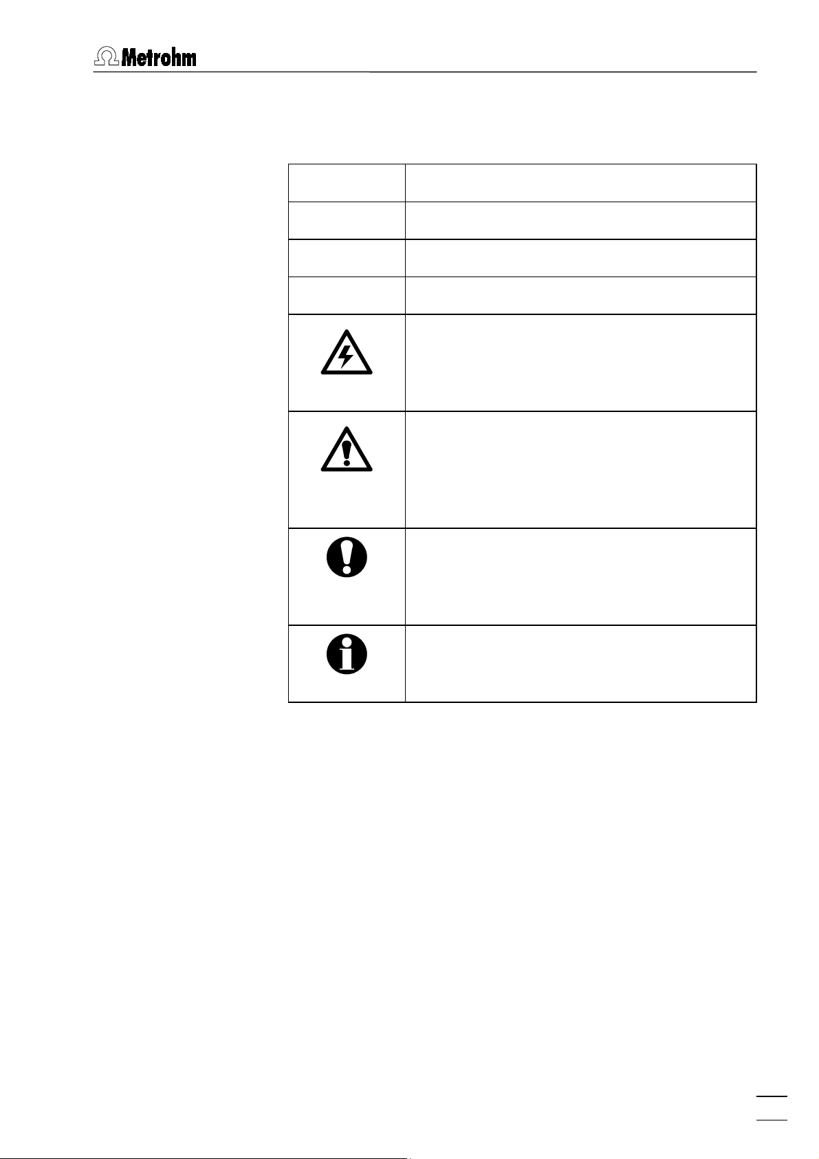
Hazard
This symbol draws attention to a possible
danger to life or of injury if the associated
directions are not followed correctly.
Warning
This symbol draws attention to possible damage to instruments or instrument parts if the
associated directions are not followed correctly.
Caution
This symbol marks important information.
First read the associated directions before
you continue.
Comment
This symbol marks additional information and
tips.
IC Net 2.1
3
Page 12
1 Introduction
1.4 Installation
1.4.1 Hardware requirements for the PC
Computer Pentium II with 200 MHz or higher
Operating system Windows¥ 95, Windows¥ 98,
Free space on hard disk 12 MB for program files
Working memory RAM 32 MB for Windows® 95 and Win-
Graphics resolution 800×600, better 1024×768 or more
Printer Any printer supported by the operat-
1.4.2 Software Installation
Windows¥ NT or Windows¥ 2000
50 MB recommended for data files
dows® 98, 64 MB for Windows® NT,
128 MB for Windows¥ 2000
ing system
If you want to update from IC Net 2.0 to IC Net 2.1, proceed as
described in section 1.4.3.
Insert installation CD into CD drive. Select
the file
setup.exe
on the CD and click on
<OK>
<Start>
and
. Click on
Run
IC Net
. Find
the selection menu and follow the setup program instructions.
The two software packages «IC Net 2.1» and «Autodatabase
1.0» will be installed in the desired directory. Icons are created in
the program folder, in the startup folder, and on the desktop. In
addition to the program files of the «IC Net» program, the following folders are installed:
Folder for storage of chromatogram files (
Data
and batch reprocessing files (
) with several
*.bar
examples.
Devices
Log
Methods
Folder for storage of device files.(
Folder for storage of exception files.(
tory files (
), and log files (
*.hst
Folder for storage of data acquisition method
files (
) and sample queue files (
*.mtw
*.log
*.dev
).
).
*.exc
*.que
several examples.
in
*.chw
), his-
) with
)
4
Reports
Systems
Folder for storage of report files (*) and graphic
files (
Folder for storage of system files (
*.wmf
).
*.smt
).
IC Net 2.1
Page 13

1.4 Installation
1.4.3 Software update
For software update from IC Net 2.0 to IC Net 2.1, proceed as follows:
1. Switch on PC and start operating system.
2. If you want to save chromatograms, methods and system files
created by IC Net 2.0, backup the folders
Systems
in another directory on the hard disk.
Data, Methods
, and
Systems of IC Net 2.0 containing 761 Compact IC icons cannot be used in IC Net 2.1 any more. Delete these systems before making the backup of the
Systems
folder.
3. If you want to save data created by Autodatabase 1.0, backup
the folders
Filters, Report templates
, and
User database
in an-
other directory on the hard disk.
4. Deinstall the IC Net 2.0 software by selecting
/ Control panel
Metrohm IC Net 2.0
, double-clicking the
in the list and clicking on
Software
<Start>
icon, selecting
<Add/remove>
program files and icons should be removed.
5. Delete the folder
IC Net 2.0
in the program folder.
6. Install the IC Net 2.1 software (see section 1.4.2).
7. Copy the IC Net 2.0 backup files of the folders
and
Systems
2.1\IC Net\Methods
into the folders
, and
..\IC Net 2.1\IC Net\Systems
..\IC Net 2.1\IC Net\Data, ..\IC Net
Data, Methods
.
8. Copy the Autodatabase backup files of the folders
port templates
2.1\Autodatabase\Filters
, and
plates
, and
User database
..\IC Net 2.1\Autodatabase\User database
,
..\IC Net 2.1\Autodatabase\Report tem-
into the folders
..\IC Net
.
/
Settings
. All
Filters, Re-
,
IC Net 2.1
5
Page 14

1 Introduction
1.4.4 Software deinstallation
Select
icon. Select
<Add/remove>
1.4.5 Demo version
If the «IC Net Software 2.1» is installed on a PC without installation of IC system components, this software can be used as a
demo version which is restricted to the display and recalculation of already recorded chromatograms.
1.4.6 Registration
Please send us your 8.110.8207 Registration card as soon as
possible. Only registered users will get updated program versions
at a special price.
<Start>
/
Settings / Control panel.
Metrohm IC Net 2.1
. All program files and icons should be removed.
Double-click the
in the list and click on
Software
6
IC Net 2.1
Page 15
2.1 Starting/closing the program
2 Fundamentals of the operation
2.1 Starting/closing the program
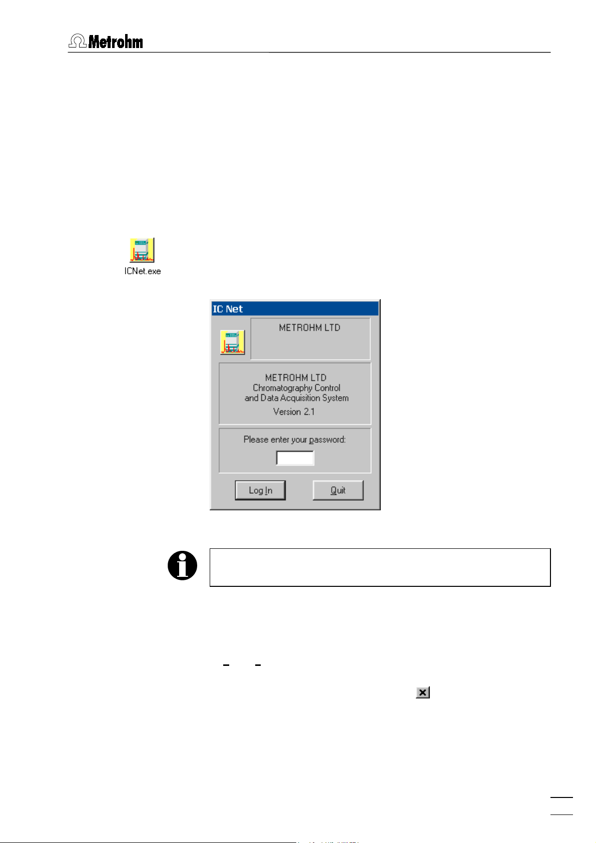
2.1.1 Start the «IC Net» program
Start the program
Double-click this icon or the
program. The
IC Net
login window appears:
ICNet.exe
file to start the «IC Net 2.1»
Enter your password and click on
After software installation, the program can be started without
entering a
2.1.2 Close the «IC Net» program
IC NET / File / Exit (Alt+F4)
Exit the «IC Net 2.1» program.
The program is also quit by clicking on in the upper right part
of the main window.
Password
<Log In>
. For the definition of users, see section 3.2.
.
IC Net 2.1
7
Page 16

2 Fundamentals of the operation
2.2 Glossary
Batch reprocessing
Batch reprocessing is understood to be the subsequent reprocessing of a series of chromatograms which have been loaded in
a batch reprocessing queue. During reprocessing with a selected
method the settings for calibration, integration, passport, appearance and report can be altered at will (for details, see section 10).
Calibration
Calibration is used to describe the method of determining the relationship between the peak height or peak area found for one
component and its concentration in the sample. The result of the
calibration is a calibration function (calibration curve), which
shows the relationship between the amount of sample and the
evaluated quantity.
The determination of the calibration function with reference solutions can be carried out as a one-point or as a multiple-point
calibration. The calibration method which is mainly used in ion
chromatography is the external standard calibration (absolute
calibration); calibration with an internal standard (relative calibration) or tabulated calibration are also possible (for details,
see section 4).
Chromatogram
A chromatogram is a graphic plot of the elution curve (signal vs.
time) recorded following a chromatographic separation on a
separating column.
Chromatograms are stored as chromatogram files (
directory. As well as the measuring data the chromatogram
Data
files also contain the method parameters and system settings
which have been used for data recording, data processing and
remote control (for details, see section 8).
Determination
In order to carry out a determination a suitable system must be
selected for the separating problem. The result of the determination is a chromatogram, in which the measuring data and results
of the determination are stored (for details, see section 8).
Device
The «IC Net» program supports remote control for Metrohm and
Bischoff instruments. Each instrument within a system is a de-
vice. Devices are stored as device files (
rectory. All Metrohm devices start with
devices start with
Bi*.dev
) in the
*.dev
Me*.dev
and all Bischoff
(for details, see section 6).
*.chw
Devices
) in the
di-
8
Integration
Integration is to be understood as being the method for determining the peak area and peak height with the aid of approximate
baselines. The integration algorithm included in the program is in-
IC Net 2.1
Page 17

2.2 Glossary
fluenced by the integration parameters and the optionally programmable integration events which are defined in the method.
In addition, the integration can be manually corrected later with
the aid of the peak editor (for details, see section 7).
Interface
The «IC Net» program supports remote control for interfaces
available from Metrohm and Bischoff. Interfaces generally convert
analog signals to digital form, which can be handled by the computer. Interfaces are stored as device files (
*.dev
) in the
Devices
di-
rectory. All Metrohm interfaces and Metrohm devices start
with
with
Me*.dev
Bi*.dev
; all Bischoff interfaces and Bischoff devices start
(for details, see section 5).
Method
A method contains all information necessary for data acquisition, integration, peak evaluation and quantification. It can
be considered as the chromatogram template, i.e. chromatogram
without raw data. Methods are stored as method files (
the
Methods
directory.
*.mtw
) in
Each system is linked to a method. This method is called proc-
essing method and is opened automatically at the start of a new
determination (for details, see section 7).
Sample queue
A sample queue is used for the automated processing of series
of samples, particularly in combination with a sample changer (for
details, see section 9).
System
The combination of Metrohm and Bischoff devices connected to
an interface is called a system. The system includes all the settings of the devices, their time program, the data acquisition parameters and the processing method which have been optimized
for the specific separating column and the determination to be
carried out with it. A system is used to start single determinations
or determinations with the help of a sample queue.
Systems are stored as system files (
tory (for details, see section 4).
Workplace
The workplace contains all interfaces and systems connected to
the PC COM. The icons of all these active interfaces and systems
are shown on the toolbar. They can also be displayed in the
window opened by selecting the
place
menu item (for details, see section 3.3).
) in the
*.smt
Options / Devices setup
Systems
direc-
Work-
IC Net 2.1
9
Page 18
2 Fundamentals of the operation
2.3 Overview of program windows
«IC Net 2.1» consists of different windows whose functionality is
linked together. The different windows are:
IC NET
CHROMATOGRAM
SYSTEM
SYSTEM STATE
WATCH WINDOW
QUEUE EDITOR
Main program window with menus for file
System window for control of interfaces and
System state window for status messages.
Watch window for live display of instrument
Queue editor window for edition of sample
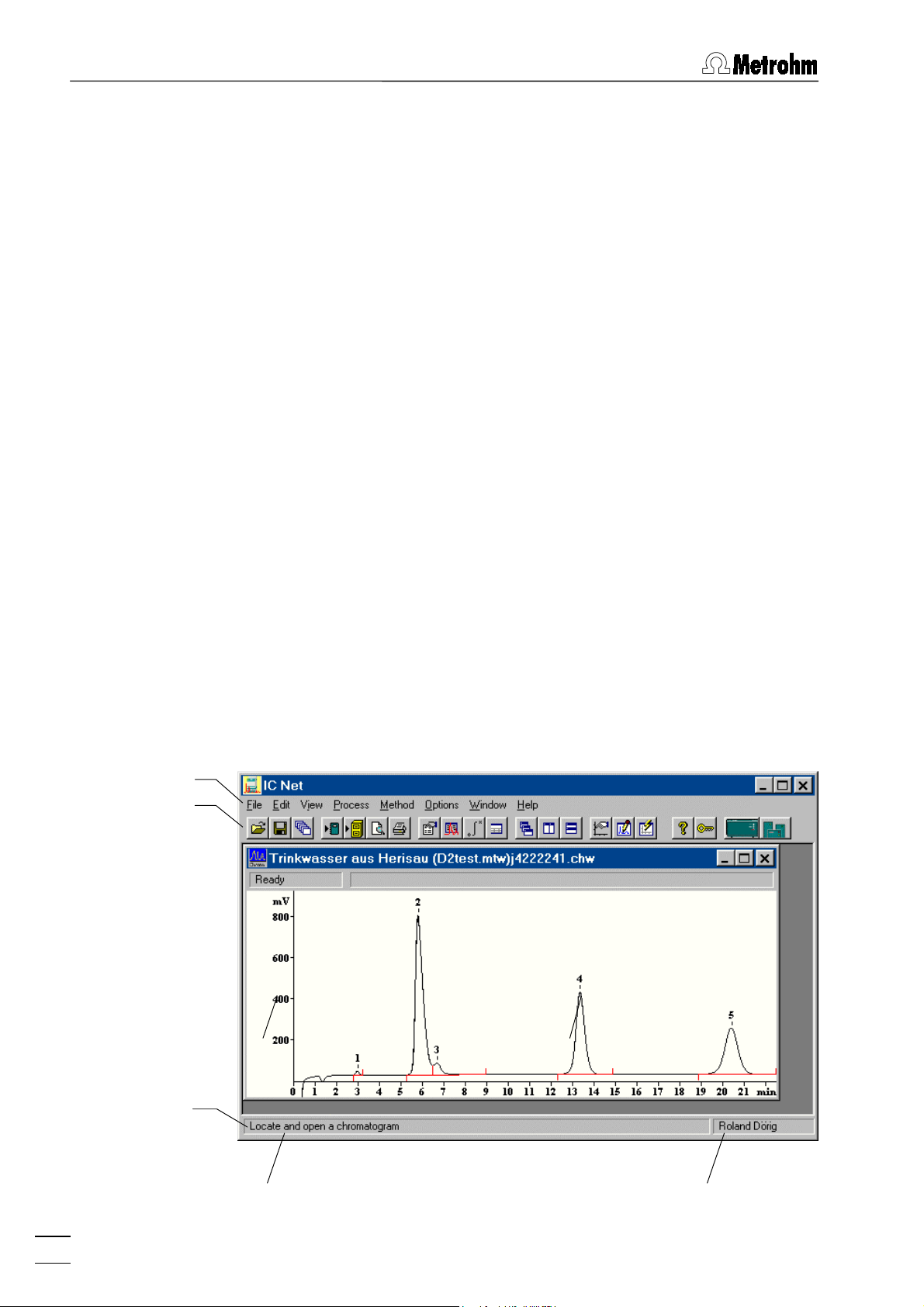
2.4 Main window elements
administration, printing, method modification, options, login and user rights, window
handling.
Chromatogram window for graphic plot of
running or recorded chromatograms.
devices.
values.
queue tables and batch reprocessing tables.
The elements of the
IC NET
main window are the menu bar, the
toolbar and the status bar, indicating prompts and logged-in user.
Menu bar
Toolbar
Status bar
Prompts, information
Logged-in user
10
IC Net 2.1
Page 19
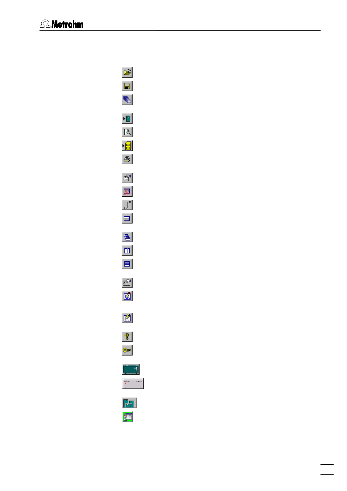
2.5 Icons of the main window
2.5 Icons of the main window
The following icons are displayed in the
IC NET
Open chromatogram
Save chromatogram
Open last batch reprocessing file
Make report
Print preview
Send chromatograms to Autodatabase
Print chromatogram
Passport
Method setup
Integration
Components
main window:
Cascade all opened chromatogram windows
Vertical tiling of open chromatogram windows
Horizontal tiling of open chromatogram windows
Appearance
Enable/disable peak editor mode. If the Peak editor
mode is enabled, the peak editor icons appear.
View all
Help
Lock system
762 IC Interface
771 Compact Interface
Connected system
IC Net 2.1
Global timer
11
Page 20

2 Fundamentals of the operation
2.6 Overview of file types
The following file types are produced by the «IC Net» software:
Autodatabase file
*.adb
Contains chromatogram and method data of all determinations.
Batch reprocessing file (binary file)
*.bar
Contains batch reprocessing data. The
stored automatically in the
Calibration file (binary file)
*.cal
Contains calibration data, which can be exported with
Net / Method / Calibration / Export calibration
The
*.cal
folder.
Chromatogram file (binary file)
*.chw
Contains chromatogram, system and method data of a
determination.
The
*.chw
*.bar
folder.
Data
file is stored automatically in the
file is stored automatically in the
file is
.
Methods
folder.
Data
IC
Exception file (ASCII file)
*.exc
Contains exceptions from normal running and error
messages.
The
file is stored automatically in one of the day
*.exc
subfolders of the
History file (ASCII file)
*.hst
Contains history of commands and program actions.
The
file is stored automatically in one of the day
*.hst
subfolders of the
Log file (ASCII file)
*.log
Contains log file of data communication between PC
and instruments.
The
file is stored automatically in one of the day
*.log
subfolders of the
Method file (binary file)
*.mtw
Contains the data acquisition method, which can be
linked to a system.
The
file is stored automatically in the
*.mtw
folder.
Log
Log
Log
folder.
folder.
folder.
Methods
12
Sample queue file (binary file)
*.que
Contains a sample data table.
The
file is stored automatically in the
*.que
folder.
Systems
IC Net 2.1
Page 21

2.7 Context-sensitive menus
Report file (ASCII file)
*.rtt
Contains a report template.
The
System file (ASCII file)
*.smt
file is stored in the program folder.
*.rtt
Contains the system settings.
The
file is stored automatically in the
*.smt
Systems
folder.
Device file (ASCII file)
*.dev
Contains drivers for devices.
The
file is stored in the
*.dev
Devices
folder.
2.7 Context-sensitive menus
Some of the menu functions of the program windows are also accessible by clicking on the desired window or item and pressing
the right mouse button. The pop up windows have different
contents and functions depending on the selected active window
or item type.
2.8 Keyboard and mouse functions
The mouse can be used to carry out the normal program operat-
ing functions such as the selection of menu items and fields. It
can additionally be used for magnifying a section of a chromatogram (zooming). To zoom a portion of the plot it is necessary
to place the mouse cursor to the upper left corner of the square
to zoom, press the left mouse button and drag the cursor to the
lower right corner of the rectangle. After releasing of the left
mouse button the selected region will be zoomed full-screen. If
the cursor is active in the peak editor mode then it can be moved
by pressing down the right-hand mouse key.
The keyboard can also be used to scale a chromatogram in the
window, as described below.
Keyboard quick reference
Cursor is inactive:
[ up ] Increases sensitivity on the Y axis.
[ down ] Reduces sensitivity on the Y axis.
[ right ] Expands a chromatogram on the X axis.
IC Net 2.1
[ left ] Shrinks a chromatogram on the X axis.
[ Ctrl ] + [ Home ] Autoscale procedure on the X axis (shows
all on X).
[ Ctrl ] + [ End ] Autoscale procedure on the Y axis (shows
all on Y).
[ PageUp ] Shifts a chromatogram on 1/10 part of a
screen upwards.
13
Page 22

2 Fundamentals of the operation
[ PageDown ] Shifts a chromatogram on 1/10 part of a
[ Shift ] + [ up ] Increases a distance between channels of a
[ Shift ] + [ down ] Reduces a distance between channels of a
[ 0 (Zero) ] Adjusts a zero on the last point of a chro-
Only part of the chromatogram is on screen:
[ Ctrl ] + [ right ] Moves one window right (without change of
[ Ctrl ] + [ left ] Moves one window left (without change of
[ Home ] Shows the beginning of a chromatogram
[ End ] Shows the end of a chromatogram (without
screen downwards.
chromatogram.
chromatogram.
matogram (running chromatogram) or its
lowest level (finished run).
scale on X and Y axes).
scale on X and Y axes).
(without change of scale on X and Y).
change of scale on X and Y).
2.9 Help
[ 0 (Zero) ] Adjusts a zero on the lowest level in the
window.
Cursor is active:
[ 0 (Zero) ] Adjust a zero in site of the cursor.
[ right ] Moves cursor left to right.
[ Shift ] + [ right ] Quickly moves cursor left to right.
[ left ] Moves cursor to the left.
[ Shift ] + [ left ] Quickly moves cursor to the left.
[ Home ] Moves cursor to beginning of a window.
[ End ] Moves the cursor to end of a window.
[ Shift ] + [ End ] Sets the beginning of a window in site of
the cursor.
[ Shift ] + [ Home ] Sets the end of a window in site of the cur-
sor.
By clicking on , by clicking on , by selecting the
Help / Contents
menu item, or by pressing the [ F1 ] key you can
get on-line help on the current topic anywhere in the program.
14
Green texts can be clicked to jump to a different Help
topic.
Violet texts identify the dialog item, parameter or button
in the corresponding window.
Blue texts identify important information.
IC Net 2.1
Page 23
3.1 Fonts
3 Software settings
3.1 Fonts
IC NET / Options / Fonts
This option allows the selection of fonts used by the system.
Font for dialogs...
Selection of font used for dialog boxes.
Default setting:
Font for reports...
Selection of font used for report output to the
screen or printer.
Default setting: Courier New / Standard / 10 pt.
Font for tables...
Selection of font used for data presentation in
tables on the screen. It is not used for presentation of tables in the report.
Default setting:
Font for plots...
Selection of font used for labels on chroma-
togram plots and calibration curves.
Default setting:
Save fonts configuration
Save chosen font configuration.
If you want to reset the modified font settings to the
initial default settings, delete the
program path.
MS Sans Serif / Standard / 8 pt.
MS Sans Serif / Bold / 8 pt.
Times New Roman / Bold / 10 pt.
fonts.cfg
file in the
3.2 Security system
The «IC Net» program has a security system based on the list of
users. Every user has his unique password and one of the following access levels:
Restricted access to program functions. Al-
Access to all program functions with few ex-
IC Net 2.1
Novice
Master
lows only start and stop of determinations using existing system and method files and
manual control of the devices. Modifications of
system, method and data files are not allowed.
ceptions: the user cannot set
Global prefer-
15
Page 24
3 Software settings
ences
, open the
Workplace
window, change
hardware settings of interfaces and devices,
and change
Security
options.
Administrator
Access to all program functions. This level
should be switched on only while installing the
system or in the case of configuration change.
The administrator user is authorized to change
access levels, names and passwords of other
users
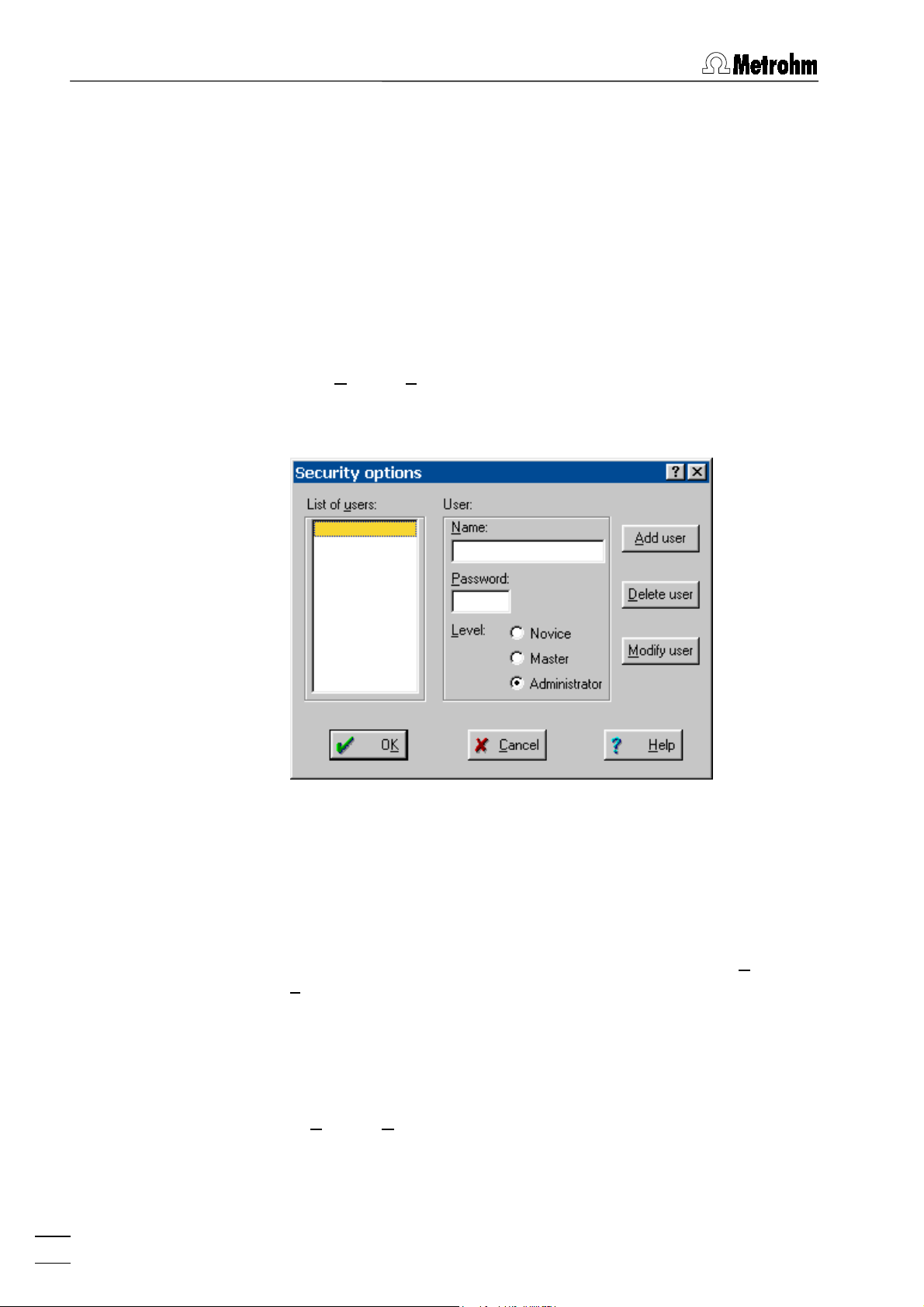
It is recommended to make user lists and enter passwords as a
first action after software installation. So, select the menu item
NET / O
ptions / Security
and click on
<Log In>
window without entering a password. The
in the
Security options
IC Net
login
IC
window
appears:
Enter user name, password and access level for all users. Don't
forget to make one of the user an
window will not open again. At the end, click on
After configuration of the security system the program prompts for
the password every time the system starts. This user name
stamps all methods, chromatograms and reports. It is possible at
any time to change the user with the menu item
L
ock system
3.3 Global settings
IC NET / Options / Global preferences
This window is used for global program settings. It can be
opened only by the user with
Administrator
, otherwise this
.
<OK>
IC NET / Options /
.
Administrator
access level.
16
IC Net 2.1
Page 25

3.3 Global settings
Data file overwrite
Chromatogram files cannot be overwritten.
Never
Ask
Always
If method changed
Don't ask to save
Ask to save
Overwrite without asking
If disk method is newer
Chromatogram files are always overwritten
Global settings for overwriting of chroma-
Global settings for saving of method files:
The method file is not saved automatically.
togram files:
A modified chromatogram is saved as new
file with the file name number raised by 1.
The user is asked if the chromatogram
should be overwritten.
without confirmation.
It can be saved only with
ethod
.
M
File
/
Save /
The user is asked if the method should be
saved.
Method files are overwritten without confirmation.
Global settings for overwriting of method
files:
IC Net 2.1
Ask to overwrite
The user is asked if the method should be
overwritten.
Overwrite without asking
Method files are overwritten without
confirmation.
Opening chromatograms
Global settings for opening chromatograms:
17
Page 26

3 Software settings
Ignore last data directory
If this option is enabled, the directory is
opened where the current selected chromatogram is saved.
If this option is disabled, the directory is
opened where the last opened chromatogram is saved.
GLP On
System face
OK, Apply buttons mean
Switch on/off global GLP settings. The fol-
Stacked recorder icons
Save object to file
with file name confirmation
lowing parameter settings are automatically
set:
Data file overwrite = Never
If method changed = Don't ask to save
If disk method is newer = Ask to overwrite
If this option is enabled, only one recorder
icon with different tabs appears in the system window if several data recorders are
installed.
If this option is enabled, the
<Apply>
button
in system settings windows is replaced by
the
<Save>
saved if the
button. The system settings are
<Save>
or
<OK>
button is
clicked.
If this option is enabled, the
<Apply>
button
in system settings windows is replaced by
the
<Save as>
can be saved in a new file if the
or
<OK>
button. The system settings
button is clicked.
<Save as>
18
Chromatogram units
Flow
Pressure
Print via print spooler
<Default colors>
Default colors for chromatographic win-
Units for chromatograms:
Unit for flow rate:
Unit for pressure:
PPPPL/min
MPa, psi, bar, atm
,
mL/min
Switch on/off printing via print spooler.
Switch off this option if problems with printing occur.
dows (details see section 8.3.1).
IC Net 2.1
Page 27
4.1 System creation
4 Systems
The combination of Metrohm and Bischoff devices connected to
an interface is called a system. The system includes all the settings of the devices, their time program, the data acquisition parameters and the processing method which have been optimized
for the specific separating column and the determination to be
carried out with it. A system is used to start single determinations
or determinations with the help of a sample queue. Systems are
stored as system files (
4.1 System creation
*.smt
) in the
Systems
directory.
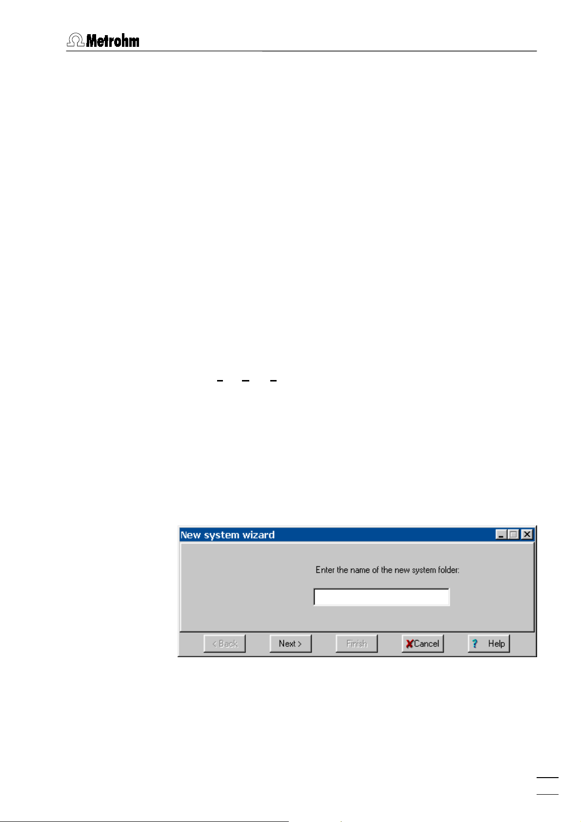
4.1.1 System wizard
IC NET / File / New / System
The
New system wizard
opened. The
routine step-by-step to build a new system
system installation is reached with
<Back>
The first step of the system installation is to enter a name for a
new system folder within the «IC Net» program path
...\ICNet\Systems
should be created.
window and a new
New system wizard
guides you trough the installation
system. The next step of the
systemsystem
<Next>
SYSTEM
, the previous step with
and the installation is completed with
. For every instrument combination, a new folder
window are
<Finish>
.
IC Net 2.1
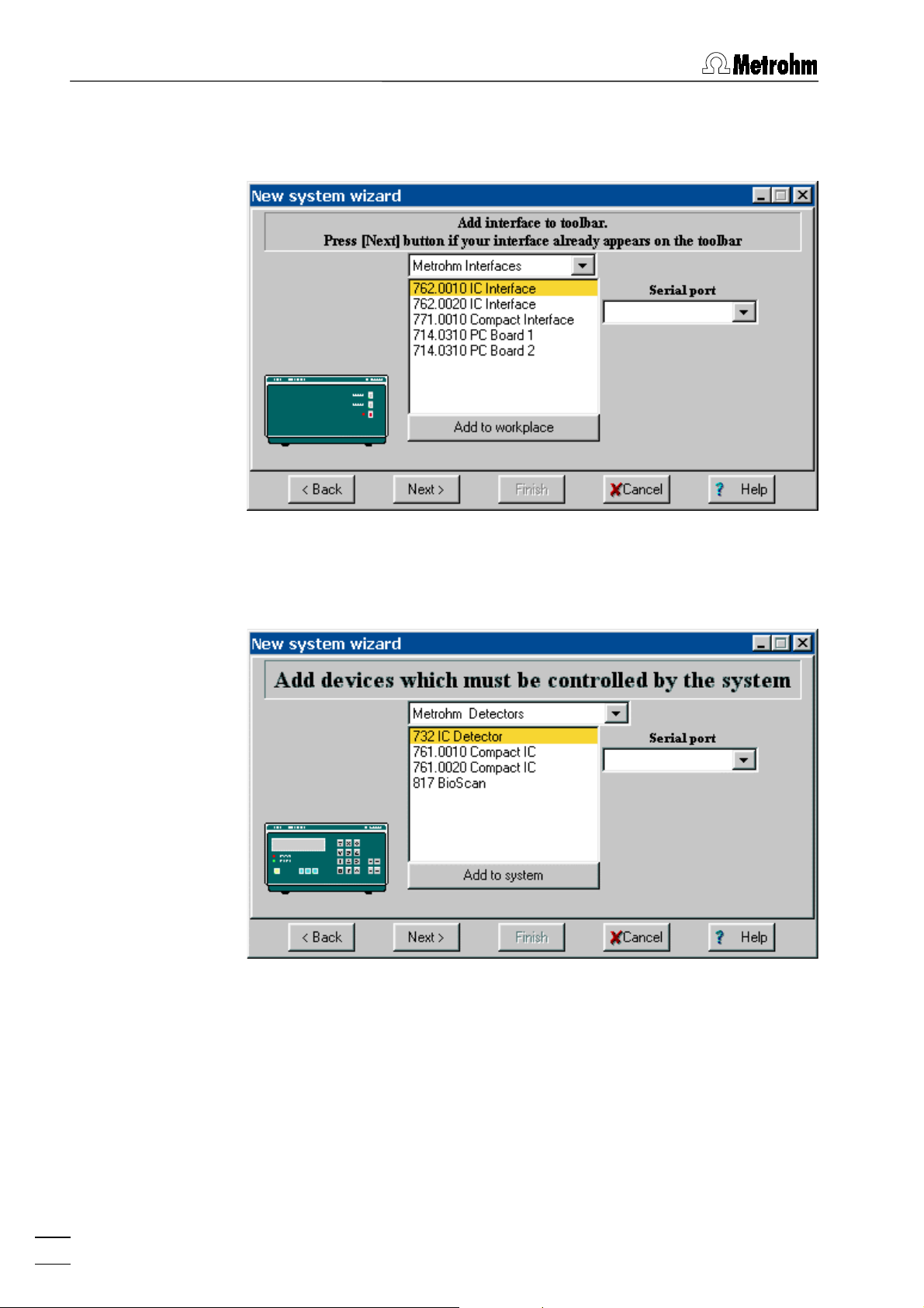
After clicking on
<Next>
, the window for addition of interfaces to
the toolbar appears. This step can be skipped if the desired interface has been already added to the toolbar (see section 5.1.2). If
this is not the case, the interface has to be selected from the
Metrohm Interfaces
or
Bischoff Interfaces
groups. After selecting the
serial port where the interface is connected to and clicking on
19
Page 28
4 Systems
<Add to workplace>
, the interface icon will appear on the toolbar
(PC Boards will not appear on toolbar).
After clicking on
<Next>
, the window for addition of devices (see
6.1.1) to the system window appears.
For every device to be controlled with «IC Net», open the group
which contains this device, select the device and the
Serial port
the interface where the device is connected to. After clicking on
<Add to system>
, the device is added to the
SYSTEM
desired, an additional data recorder and a timer of the
group can be added to the system.
ules
window. If
More mod-
of
20
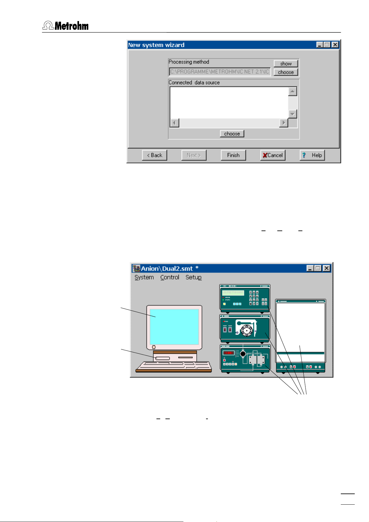
After clicking on
<Next>
, the window for selection of processing
method linked to the system and data source appears (details
see section 6.16.2).
IC Net 2.1
Page 29
4.1 System creation
After clicking on
tem as a system file
system is now ready to start a determination (see section 4.3.3).
4.1.2 System window
A system window is opened with
the selection of the desired system file. It contains icons for Data
recorder, Watch window (screen) and all the devices installed
with the system wizard.
Watch window
<Finish>
system file (
system filesystem file
, the user is asked to save the new sys-
) in the new system folder. The new
*.smt
IC NET / File / Open / System
and
4.1.3 Add devices to an existing window
SYSTEM / Setup / New devices/ Install new device
Add new devices to the open
to be added to the system, open the group which contains this
device and select the device and the serial port of the interface
where the device is connected to. After clicking on
, the device is added to the
tem>
additional data recorder and a timer of the
can be added to the system.
IC Net 2.1
SYSTEM
SYSTEM
Devices
window. For every device
<Add to sys-
window. If desired, an
More modules
group
21
Page 30

4 Systems
4.2 System file handling
The following menu items are used for opening, changing, saving
and closing of systems:
IC NET / File / Open / System
Load an existing system file (
open the corresponding
and of the system file are displayed in the title bar of the
window. A star ( * ) at the end of the name indicates that the system settings have been changed since the last saving.
SYSTEM / System / Open other
Load an existing system file (
in the
rameter settings. The old system remains connected.
SYSTEM / System / Change
Open the selected new system in the desired system folder. The
current system is disconnected and closed, and the new system
is connected.
Systems
) from the
*.smt
SYSTEM
window. The name of the folder
) from the desired system folder
*.smt
directory and open a new
Systems
SYSTEM
directory and
SYSTEM
window for pa-
SYSTEM / System / Save
Save the current system file (
Systems
SYSTEM / System / Close
directory.
Close the selected system.
Delete a system
To delete an existing system, delete the
folder.
4.3 System functions
4.3.1 Connect and disconnect system
To make possible manual control of the system devices and start
of determinations, the selected system must be connected to the
workplace. Systems are connected and disconnected as follows:
) in the desired folder of the
*.smt
file in the
*.smt
Systems
22
SYSTEM / Control / Connect to workplace
Connect selected system to the workplace. Only one system from
the same system folder can be connected at the same time.
The icon appears on the toolbar. If this icon is clicked, the
SYSTEM
window is always displayed in front of all other windows.
IC Net 2.1
Page 31

4.3 System functions
SYSTEM / Control / Disconnect from workplace
Disconnect selected system from the workplace. If a system is
disconnected, manual control is not available for this system, but
all other system settings can be modified and saved.
mination
and
Startup hardware
is only possible if no other system
Start deter-
from the same system folder is connected. In this case, the system is automatically connected.
4.3.2 Start/stop hardware and record baseline
SYSTEM / Control / Startup hardware (Measure Baseline)
With this menu item the following actions are executed automatically:
x Send
System startup values
to the devices.
x Start Metrohm solvent delivery systems and Bischoff solvent
delivery systems.
x Start Metrohm additional modules and Bischoff additional
modules.
x Start Bischoff detectors.
x Switch Metrohm Autosamplers and Bischoff Autosamplers to
remote control.
x Start recording of the measurement signal using the method of
the connected system. Independently of the set chromatogram
Duration
, the measurement signal is recorded until the data ac-
quisition is stopped if a new determination is started with
determination
or by clicking the icon of the chromatogram
window. In this case the user is asked if the recorded baseline
should be saved or not.
SYSTEM / Control / Shutdown hardware
With this menu item the devices are stopped as follows:
Start
IC Net 2.1
x Stop Metrohm solvent delivery systems and Bischoff solvent
delivery systems.
x Stop Metrohm additional modules and Bischoff additional
modulesVariotherm.
x Stop Bischoff detectors.
x Switch Metrohm Autosamplers and Bischoff Autosamplers to
local control.
x Stop running determination.
x Stop active sample queue.
SYSTEM / Control / Stop data acquisition
Stop recording of the baseline.
23
Page 32

4 Systems
4.3.3 Start/stop determinations
SYSTEM / Control / Start determination
Start determination using the settings of the selected system.
At this start command, the
vices. The time programs of the different devices and the data recording are started either immediately (
after switching the injection valve to the "Inject" position (
) as set in the
inject
SYSTEM / Control / Stop determination
Start mode
Stop running determination. Data acquisition and time pro-
grams are terminated immediately. The recorded chromatogram
is saved automatically if the
on the
Passport / Processing
Alternatively the determination can be stopped by clicking the
icon of the chromatogram window. In this case the user is asked
always if the determination should be saved or not.
System startup values
Start with determination
are set at the de-
window.
Save chromatogram after the run
tab is enabled.
) or
Start with
option
If the
Auto restart
queue is active, a new determination is started immediately after the running determination is stopped. If you
want to avoid this, disable the
the sample queue.
Pause
SYSTEM / Control / Stop data acquisition
Stop data acquisition of the running determination immediately
and save the recorded chromatogram automatically if the
chromatogram after the run
is enabled. The time programs of the running determination are
continued normally.
4.3.4 Options for determinations
SYSTEM / Control / Auto restart
If this option is enabled, a new determination is started automatically using the current system after the preceding determination
has been finished normally or stopped manually.
option is enabled or if a sample
option or
option on the
Auto restart
Passport / Processing
Save
tab
24
The Auto restart option is disabled if determinations are made
with an active sample queue. This option allows to make an infinite batch cycle with the current system
SYSTEM / Control / Verify sample
If this option is enabled, the
Edit sample description
window is
opened automatically at the start of each determination for entry
of the following sample information:
IC Net 2.1
Page 33

4.3 System functions
User defined identifier (title) for the chroma-
Ident
togram to be displayed in the title bar of the
chromatogram window and in the
togram
open
window.
Chroma-
Calibration level
Info 1 / Info 2
Volume
Dilution
Vial number
Amount
Internal standard amount
Date/time when...
Injected volume in PL.
Dilution of the sample.
Sample amount. If this value is different for
Calibration level (0 = sample; 1}n = cali-
Sample description.
Autosampler vial position to take sample
Date and time of sample collection (the de-
bration solutions).
from.
the calibration run (c) and the sample run
(s), the component concentrations of the
sample are calculated as follows:
C
= Cc •
s
Amount
/
Amount
s
c
Concentration of the internal standard
component for relative concentration calculations.
fault values are equal to the date and time
when the chromatogram starts).
IC Net 2.1
The
Verify sample
option is disabled if determinations are made
with an active sample queue.
25
Page 34

4 Systems
4.4 System settings
4.4.1 Modify system window
SYSTEM / Setup / Drag icons
If this option is enabled, the device icons can be resized and
moved in the
be resized.
To resize an icon or the window, move the cursor to the desired
object until
the object to the desired size.
To move an icon, move the cursor to the desired object until
appears. Press the left mouse button and move the object to the
desired place.
4.4.2 Watch window display
SYSTEM / Setup / Watch window
If this option is enabled, the
opened if a determination or measure baseline is started (see
section 6.2).
4.4.3 Set start mode
SYSTEM
window and the
SYSTEM
window itself can
appears. Press the left mouse button and resize
WATCH WINDOW
is automatically
SYSTEM / Setup / Start mode
This menu item opens the
Start mode
mode for time programs and data acquisition.
This window contains the following two fields:
Start with determination
The time program of the loaded object or
the data acquisition (
at the moment the determination is
started.
window for definition of start
RECORDER
) is started
26
IC Net 2.1
Page 35

4.4 System settings
Start with inject
The time program of the loaded object or
the data acquisition (
RECORDER
) is started
at the moment the sample is injected.
The objects can be moved from one field to the other using the
or buttons.
4.4.4 Install new devices
SYSTEM / Setup / New devices/ Install new device
Add new devices to the open
SYSTEM
window. For every device
to be added to the system, open the group which contains this
device and select the device and the serial port of the interface
where the device is connected to. After clicking on
, the device is added to the
tem>
SYSTEM
additional data recorder and a timer of the
window. If desired, an
More modules
<Add to sys-
group
can be added to the system.
4.4.5 Install existing devices
SYSTEM / Setup / New devices/ Link to existing device
4.4.6 Print system parameters
SYSTEM / Setup / Parameters / Print
A report of the system parameters including the time program is
created and opened using the «Microsoft Word» program. The
file opened can be printed, saved and exported into other
*.rtf
programs. The system report includes the following elements:
STARTUP HARDWARE
Add devices to the open
SYSTEM
window which
are already present on the toolbar. This is mostly
used to add the
762 IC Interface events
. For every
device to be added to the system, select the device and click on
<OK>
.
Name of the method linked to the system
Main measurement channel
Configuration settings for the devices
System startup values
IC Net 2.1
START WITH DETERMINATION
Objects defined in the
Start mode
window.
The time programs are printed if the programs are enabled.
START WITH INJECT
Objects defined in the
Start mode
window.
The time programs are printed if the programs are enabled.
27
Page 36

4 Systems
4.4.7 Show system parameters
4.4.8 Links
SYSTEM / Setup / Parameters / Startup hardware
Display of the name of the method linked to the system, the main
measurement channel, the configuration settings for the devices,
and the system startup values.
SYSTEM / Setup / Parameters / Start with determination
Display of the objects defined in the
Start mode
window. The time
programs are displayed if the programs are enabled.
SYSTEM / Setup / Parameters / Start with inject
Display of the objects defined in the
Start mode
window. The time
programs are displayed if the programs are enabled.
SYSTEM / Setup / Links
Display of all devices of the system (including watch window and
data recorder).
4.5 System state window
The
SYSTEM STATE
connected. It shows status and error messages for this system.
Messages concerning a device are followed by
messages concerning the loaded system are followed by
name"]
lowing messages can appear:
4.5.1 Status messages
Checking on-line
On-line
UploadStartupValues
(name of the folder who contains the system file). The fol-
window is automatically opened if a system is
["device name"]
,
["folder
Checking connection between PC and device.
Connection between PC and device ok.
Hardware or system startup values have
been loaded to the device.
28
Initialisation
Ready
Starting
Hardware or system initialization.
Device is ready.
Starting program or chromatogram data
acquisition.
IC Net 2.1
Page 37

4.5 System state window
Running
Running program or chromatogram data
acquisition.
Running program
(xxx min left)
Waiting for INJECT
INJECT done
Stopping
Finished
SHUTDOWN
4.5.2 General error messages
Detection of hardware failed
Running time program with time display.
Waiting for "INJECT" to start program
and/or chromatogram data acquisition as
defined in the Start mode.
Injection valve has been switched to the
"INJECT" position.
Determination has been stopped.
Program or chromatogram data acquisition
has been finished.
System is shutdown.
Bad connection between PC and device or
device switched off (check connecting cable or switch on instrument).
4.5.3 Error messages for 761 Compact IC
LEAK DETECTED
The leak detector has detected a leak
(check IC system and connections).
E1
Program checksum wrong (call Metrohm
service).
E2
E200
RAM faulty (call Metrohm service).
Invalid instrument adjustment (call Metrohm
service).
E237
Storage of configuration values failed (repeat last action; if error reappears, call
Metrohm service).
E238
Storage of instrument number failed (repeat
last action; if error reappears, call Metrohm
service).
E240
EEPROM faulty (call Metrohm service).
IC Net 2.1
E258
Storage of setup values failed (repeat last
action; if error reappears, call Metrohm service).
29
Page 38

4 Systems
E295
Storage of memory values failed (repeat
last action; if error reappears, call Metrohm
service).
E296
E297
E298
E299
E300
E301
E302
Instrument stopped (restart instrument; if
error reappears, call Metrohm service).
Storage of remote line values failed (repeat
last action; if error reappears, call Metrohm
service).
Storage of flow correction value failed (repeat last action; if error reappears, call
Metrohm service).
Storage of break time values failed (repeat
last action; if error reappears, call Metrohm
service).
High-pressure pump faulty (restart pump; if
error reappears, call Metrohm service).
Injection valve blocked (check injection
valve; if error reappears, call Metrohm service).
Suppressor module blocked (check suppressor; if error reappears, call Metrohm
service).
E303
Storage of maintenance information failed
(repeat last action; if error reappears, call
Metrohm service).
30
IC Net 2.1
Page 39

5.1 Interface installation
5 Interfaces
The «IC Net» program supports remote control for interfaces
available from Metrohm and Bischoff. Interfaces generally convert
analog signals to digital form, which can be handled by the computer. Interfaces are stored as device files (
rectory. All Metrohm interfaces and Metrohm devices start
with
with
Me*.dev
Bi*.dev
; all Bischoff interfaces and Bischoff devices start
.
5.1 Interface installation
*.dev
) in the
Devices
di-
5.1.1 Add interfaces with system wizard
IC NET / File / New / System
The
New system wizard
opened. The
New system wizard
window and a new
routine step-by-step to build a new system
system installation is reached with
<Back>
and the installation is completed with
The first step of the system installation is to enter a name for a
new system folder within the «IC Net» program path
...\ICNet\Systems
. For every instrument combination, a new folder
should be created.
SYSTEM
window are
guides you trough the installation
system. The next step of the
systemsystem
<Next>,
the previous step with
<Finish>
.
IC Net 2.1
After clicking on
<Next>
, the window for addition of interfaces to
the toolbar appears. The interface has to be selected from the
Metrohm Interfaces
or
Bischoff Interfaces
groups. After selecting the
serial port where the interface is connected to and clicking on
<Add to workplace>
, the interface icon will appear on the toolbar
(PC Boards will not appear on toolbar).
31
Page 40

5 Interfaces
Details to the other steps of the system wizard procedure (installation of devices, processing method, and data source) see
section 4.1.1.
5.1.2 Add interfaces in workplace window
IC NET / Options / Devices setup
Open the
WORKPLACE
window which shows all interfaces and
devices installed. This window can be opened only by the user
with
Administrator
Click on
place
<Install device>
window and proceed as described in section 5.1.1.
access level.
to open the
Adding interfaces to your work-
5.1.3 Delete interfaces
IC NET / Options / Devices setup
Open the
devices installed. This window can be opened only by the user
with
click on
32
WORKPLACE
Administrator
<Delete device>
window which shows all interfaces and
access level. Select the desired interface and
to delete the interface from the workplace.
IC Net 2.1
Page 41
5.2 762 IC Interface
5.2 762 IC Interface
5.2.1 762 IC Interface features
The Metrohm 762 IC Interface is available as a one system version (2.762.0010) or a two system version (2.762.0020). Each system can control a complete ion chromatography or HPLC equipment and contains the following parts:
x Two 24-bit Analog-to-Digital Converters (often abbreviated
as ADC) to acquire two analog signals from two different detectors simultaneously (for example conductivity detection and
UV detection).
x One external start input.
x One start button at the interface front panel.
x RS232 communication ports to control up to eight devices
of a complete ion chromatography equipment.
x Seven Event output lines.
The 762 IC Interface is normally connected to a PC COM port using the 6.2134.100 connecting cable.
For detailed information about the 762 IC Interface see 762 In-
structions for Use.
5.2.2 762 icon on the toolbar
The
762 icon
is available on the toolbar if a 762 IC Interface has
been installed with the new system wizard or by using the
device>
clicking this icon the
option of the
WORKPLACE
762 IC Interface
tings opens.
5.2.3 762 icons in the system window
The
762 System 1
window if the
TEM
stalled with the
and
762 System 2 icons
762 System [1]
Install existing devices
<Install
window (see section 5.1.2). By
window for parameter set-
are available in the
or
762 System [2]
have been in-
SYS-
option (see section 6.1.3).
IC Net 2.1
By clicking this icon using the right mouse button, the following
menu items can be selected:
Open the
Open
762 System [#] window
for programming the
event output lines (this window can also be opened by
double-clicking the icon).
Unlink
Delete the
762 icon
from the system.
33
Page 42

5 Interfaces
5.2.4 762 IC Interface window
762 icon / Open
The
762 IC Interface
selecting this menu option with the right mouse button or by clicking the
tings
762 icon
, and
Links
Init
The
tab of the
Init
tion parameters for the 762 IC Interface.
window for parameter settings is opened by
on the toolbar. It consists of three tabs
Init, RS set-
.
762 IC Interface
window contains data acquisi-
Label
Optional label to name the interface with
maximum 8 characters.
ROM version
Measuring per second
Range
Range for AD converter.
Instrument program version number.
Number of data points measured per s.
Entry range:
10, 20, 30, 50, 60 points/s
Example: converts r 2500 mV to 224 bits
Entry range:
78.125, 39.062 mV
Second press on RUN/STOP means 'stop' when measuring
2500, 1250, 625, 312.5, 156.25,
If this option is enabled, the running data
acquisition will be stopped if the RUN/STOP
button on the 762 IC Interface front panel is
pressed. This is equal to
Stop determination
If this option is disabled, the running data
acquisition will not be stopped if the
RUN/STOP button on the 762 IC Interface
front panel is pressed.
.
34
IC Net 2.1
Page 43

5.2 762 IC Interface
<ASK>
Read current parameters from 762 IC Interface.
<SET>
RS settings
The
parameters for the 762 IC Interface.
Send current parameters to 762 IC Inter-
face.
RS settings
tab of the
762 IC Interface
window contains RS232
Baud Rate
Parity
Handshake
FIFO size
<ASK>
<SET>
Send current parameters to 762 IC Inter-
Baud rate of the device.
Selection:
Default value:
1200...115200
115200
Parity check.
Selection:
Default value:
None, Even, Odd
None
Enable/disable software handshake mode.
Selection:
Default value:
Swchar, none
SWchar
Intermediate memory in byte.
Selection:
1...16
Default value: 16
Read current parameters from 762 IC Interface.
face.
IC Net 2.1
35
Page 44

5 Interfaces
Links
The
Links
tab of the
762 IC Interface
is used for COM port selection
and settings.
Name of the interface or device.
Alias
COM #
If this entry is clicked with the right mouse
Put on desktop
Change
button, the following menu appears:
Possibility for setting COM port parameters
(details see on-line help).
Possibility for changing the COM port. The
following window is opened, where the
COM port can be changed by clicking on
the desired entry.
5.2.5 762 Event output lines
762 System [#] icon / Open
The
seven event output lines is opened by selecting this menu option
with the right mouse button or by double-clicking the
the
SYSTEM
setup
36
762 System [#]
window. It consists of the tabs
.
window with programs and settings for the
762 icon
Program
and
Events
IC Net 2.1
in
Page 45

5.2 762 IC Interface
Time program
On the
Program
tab of the
762 System [#]
window a user-defined
time program for the event output lines of the 762 IC Interface can
be entered. This program is started automatically as defined in
the
Start mode
the determination is started (
moment the sample is injected (
window (see section 4.4.3) either at the moment
Start with determination
Start with inject
) or at the
).
Program
The
Program
Program
Events configuration
tab contains the two following subpages:
Main time program with all program steps.
Possibility for creation of user-defined re-
mote commands.
On the
Program
subpage, program steps including time, program
instruction and parameter can be entered.
First column
Time at which program instruction is ap-
plied.
Entry range:
0.0 ... 999.9 min
If no time is entered, the program instruction is applied together with the last instruction with time entry.
Second column
Program instruction (see below).
In addition to these predefined instructions,
user-defined remote commands can be entered if activated on the
tab.
Events configuration
IC Net 2.1
Third column
Parameter for program instruction (see be-
low).
ENABLED
Enable program start (a disabled program
is not started).
<Add>
Add new program instruction.
37
Page 46

5 Interfaces
<Delete>
Delete selected program instruction.
<Verify>
Test the time program (error messages are
displayed if program is wrong).
List of program instructions
The following program instructions can be added to the time program on the
Instruction Parameter entry Meaning
Events 0, 1, p, *
Program END, RESET
Program
subpage:
Set event output lines 1...7 to the
desired values. For entry of the first
value, enter 1, 0, p or *. For entry of
the other values, move the cursor in
front of the value to be changed
and enter 1, 0, p or *.
The
flag can be used to end a
END
program, especially if the program
time should be longer than the
chromatogram duration. Additional
steps after this flag are not allowed.
The
RESET
flag is used to reset the
parameters to the system startup
values.
Events configuration
On the
Events configuration
subtab user-defined event commands
can be defined, which can be inserted into a time program after
being activated with
<Activate>
.
38
Name (1st column)
User-definable name of the event com-
mand (e.g.
Start_766
).
IC Net 2.1
Page 47

5.2 762 IC Interface
Event command (2nd column)
Setting the event output lines 1}7.
Selection:
(line off, inactive, open)
0
(line on, active, 0 V)
1
(pulse, pulse length 150 ms)
p
(leave line in current status)
*
For entry of the first value, enter 1, 0, p or *.
For entry of the other values, move the cursor in front of the value to be changed and
enter 1, 0, p or *.
<Add>
<Delete>
<Activate>
Events setup
The
Events setup
startup values for the seven event output lines of system 1 or
system 2 of the 762 IC Interface. These startup values are sent
each time the system is connected or a determination is started.
Add new remote command.
Delete selected remote command.
Activate the defined remote commands for
insertion into the time program.
tab of the
762 System [#]
window contains the
IC Net 2.1
Each event output line can be set to the following values:
Line off, inactive (open)
0
Line on, active (0 V)
1
For technical information see 762 Instructions for Use.
39
Page 48

5 Interfaces
5.3 771 Compact Interface
5.3.1 771 Compact Interface features
The Metrohm 771 Compact Interface is a two channel Analogto-Digital Converter to acquire two analog signals from two different detectors simultaneously or time independent. It contains the
following parts:
x Two 24-bit Analog-to-Digital Converters (often abbreviated
as ADC) to acquire two analog signals from two different detectors simultaneously (for example conductivity detection and
UV detection).
x Two external start inputs.
The 771 Compact Interface is normally connected to a PC COM
port using the 6.2134.100 connecting cable. The 6.2128.170 cable is used to acquire the analog signal from the 732 IC Detector
(or another detector) and to start the data acquisition with contact
closure from the 733 IC Separation Center.
For detailed information about the 771 Compact Interface see
771 Instructions for Use.
5.3.2 771 icon on the toolbar
The
771 icon
is available on the toolbar if a 771 Compact Inter-
face has been installed with the
<Install device>
option of the
5.1.2). By clicking this icon the
parameter settings opens.
5.3.3 771 Compact Interface window
771 icon / Open
The
771 Compact Interface
opened by selecting this menu option with the right mouse button
or by clicking the
Init, RS settings
771 icon
, and
Links
New system wizard
WORKPLACE
771 Compact Interface
window (see section
or by using the
window for
window for parameter settings is
on the toolbar. It consists of three tabs
.
40
Init
The
tab of the
Init
771 Compact Interface
window contains data ac-
quisition parameters for the 771 Compact Interface.
Label
Optional label to name the interface with
maximum 8 characters.
ROM version
Measuring per second
Instrument program version number.
Number of data points measured per s.
Entry range:
10, 20, 30, 50, 60 points/s
IC Net 2.1
Page 49

5.3 771 Compact Interface
Range
<ASK>
<SET>
RS settings
The
RS232 parameters for the 771 Compact Interface.
Range for AD converter.
Example: converts r 2500 mV to 224 bits
Entry range:
78.125, 39.062 mV
2500, 1250, 625, 312.5, 156.25,
Read current parameters from 771 Compact Interface.
Send current parameters to 771 Compact
Interface.
RS settings
tab of the
771 Compact Interface
window contains
IC Net 2.1
Baudrate
Parity
Handshake
Baud rate of the device.
Selection:
Default value:
1200...115200
57600
Parity check.
Selection:
Default value:
None, Even, Odd
None
Enable/disable software handshake mode.
Selection:
Default value:
Swchar, none
SWchar
41
Page 50

5 Interfaces
<ASK>
<SET>
Send current parameters to 771 Compact
Links
The
Links
tab of the
and settings (details see section 5.2.4).
5.4 Metrohm PC Board
The 2.714.0310 Metrohm PC Board Interface is a two channel
Analog-to-Digital Converter (often abbreviated as ADC) to ac-
quire two analog signals from two different detectors simultaneously or time independent (e.g. conductivity detection and UV detection).
Read current parameters from 771 Compact Interface.
Interface.
771 IC Interface
is used for COM port selection
One or two PC Boards can be installed in the same PC: PC
Board 1 is the first interface, PC Board 2 is the second interface
installed in the PC. They differ in different jumper settings on the
board. The «IC Net» program is the successor for the former « IC
Metrodata for Windows» program used to work with the PC
Boards.
The 6.2128.140 cable is used to connect the analog output of the
732 IC Detector (or another detector) and the contact closure
output of the 733 IC Separation Center to the Metrohm PC Board.
The Metrohm PC Board must be installed with the new system
wizard or by using the
<Install device>
option of the
Workplace
win-
dow (see section 5.1.2). However, there is no PC Board icon on
the toolbar after installation. The PC Board can only be seen in
the
Workplace
double-clicking the
window opened with
MeBoard1
or
MeBoard2
Options / Devices setup
item, the
MeBoard#
. By
win-
dow opens with the following tabs:
Device settings
Manual control and startup values for PC
Board (it is recommended not to change
any of these parameters!).
42
Window for COM port selection and set-
Links
tings (it is recommended not to change any
of these parameters!).
For detailed information about the Metrohm PC Board see on-line
help and Instructions for Use for «IC Metrodata for Windows».
IC Net 2.1
Page 51

5.5 Global timer
5.5 Global timer
5.5.1 Timer icon
The global timer is used for programming system tasks which are
started automatically daily or once at the desired time. The
timer icon
with the new system wizard or by using the
of the
the
Timer
5.5.2 Timer program
is available on the toolbar if the
Workplace
window (see section 5.1.2). By clicking this icon
window for parameter settings opens.
has been installed
Timer
<Install device>
Global
option
The
tem tasks on the
window contains the user-defined program for sys-
Timer
Scheduled tasks setup
tab. These tasks are
started automatically at the day and time defined in the program.
On the
tered under
The title line of the
days:hours:minutes:seconds
tab of this window, a user-defined name can be en-
Links
for the timer.
Alias
window shows the current time left in
Timer
until the next task is automatically
started.
IC Net 2.1
<New task>
<Daily>
Add a new task to the timer program.
Selecting this option opens a subwindow for
selection of the days at which the task should
be started.
<Once>
Selecting this option opens a subwindow for
selection of time and day at which the task
should be started. After the selection of the
desired program instruction the system file for
which this instruction should be applied must
be selected in the
Systems
folder.
43
Page 52

5 Interfaces
<Add subtask>
Add a new subtask for the selected daily task.
The time and program instruction for this subtask has to be entered in the opened subwindow and the system file to which this instruction should be applied must be selected in the
Systems
Delete the selected task from the timer pro-
<Del>
folder.
gram.
The following program instructions can be used for userdefined event program tasks in the
Open the selected system.
Open
Close the selected system and disconnect it
Close
Timer program
window:
from the workplace.
Startup
Start
Stop
Shutdown
Startup hardware
Start determination
Stop determination
Shutdown hardware
of the selected system.
using the selected system.
using the selected system.
of the selected system.
44
IC Net 2.1
Page 53

6.1 Device installation
6 Devices
The «IC Net» program supports remote control for Metrohm and
Bischoff instruments. Each instrument within a system is a de-
vice. Devices are stored as device files (
rectory. All Metrohm devices start with
devices start with
6.1 Device installation
Bi*.dev
.
) in the
*.dev
Me*.dev
Devices
di-
and all Bischoff
6.1.1 Install devices at system creation
IC NET / File / New / System
The
New system wizard
opened. The
New system wizard
window and a new
routine step-by-step to build a new system. The next step of the
system installation is reached with
<Back>
and the installation is completed with
The first step of the system installation is to enter a name for a
new system folder within the «IC Net» program path
...\ICNet\Systems
. For every instrument combination, a new folder
should be created.
SYSTEM
window are
guides you trough the installation
<Next>
, the previous step with
<Finish>
.
IC Net 2.1
After clicking on
<Next>
, the window for addition of interfaces to
the toolbar appears (details see section 4.1.1).
After clicking on
<Next>
, the window for addition of devices to the
system window appears.
45
Page 54

6 Devices
For every device to be controlled with «IC Net», open the group
which contains this device, select the device and the
Serial port
the interface where the device is connected to. After clicking on
<Add to system>
, the device is added to the
SYSTEM
desired, an additional data recorder and a timer of the
group can be added to the system.
ules
window. If
More mod-
of
Details to the other steps of the system wizard procedure (processing method, data source) see section 4.1.1.
6.1.2 Install new devices in system window
SYSTEM / Setup / New devices/ Install new device
Add new devices to the open
system wizard
window (see above). For every device to be added
SYSTEM
to the system, open the group which contains this device and select the device and the serial port of the interface where the device is connected to. After clicking on
is added to the
SYSTEM
corder and a timer of the
window. If desired, an additional data re-
More modules
the system.
6.1.3 Install existing devices in system window
SYSTEM / Setup / New devices/ Link to existing device
Add devices to the open
are already present on the toolbar. This is mostly
used to add the
762 IC Interface events
device to be added to the system, select the device and click on
<OK>
6.1.4 Delete devices
window using the
<Add to system>
New
, the device
group can be added to
SYSTEM
window which
. For every
.
46
Icon / Unlink
Devices in a
SYSTEM
window can be deleted by clicking on the
device icon using the right mouse button an select the
menu item.
Unlink
IC Net 2.1
Page 55

6.2 Watch window
6.2 Watch window
6.2.1 Watch window icon
The watch window icon is one of the components always present in a new
SYSTEM
this icon is clicked with the right mouse button, the following
menu item appears:
window. If the system is connected and
Open the
Open
Unlink
Delete the
6.2.2 Watch window settings
Watch window icon / Open
The
WATCH WINDOW
and devices included in the connected system. It can be set to be
opened automatically if a determination or measure baseline is
started with
The
WATCH WINDOW
SYSTEM / Setup / Watch window
frame titles inside the window with the right mouse button. This
opens the following menu:
WATCH WINDOW
for live display of
instrument values (this window can also be
opened by double-clicking the watch window icon).
WATCH WINDOW
window (not recommended).
TEM
from the
SYS-
displays all live parameters of the interfaces
(see section 4.4.2).
can be configured manually by clicking the
IC Net 2.1
Manual arrange
Possibility to select the parameters which
should be shown or to rearrange the sequence of the displayed parameters. This
option opens the
Data source
window for selection of the parameters to be displayed in
the watch window. The
Connected
field
shows the parameters to be displayed, the
Available
field shows the parameters not to
be displayed. The parameters can be
moved from one field to the other using the
or button.
Auto arrange
Automatic arrangement of all important pa-
rameters.
47
Page 56

6 Devices
The colors of the watch window fields and of the
SYSTEM STATE
window can be changed by clicking the fields with the right
mouse button. This offers the following possibilities:
Choose color / Foreground / Out of range
Set display color for field numbers if the
measurement value is out of range (overflow or out of limits).
Choose color / Foreground / In range
Set display color for field numbers if the
measurement value is inside the normal
range.
Choose color / Foreground / Active
Set display color for field characters in the
SYSTEM STATE
Choose color / Foreground / Passive
window for running tasks.
Set display color for field characters in the
SYSTEM STATE
Choose color / Background / Out of range
window for finished tasks.
Set display color for field background if the
measurement value is out of range (overflow or out of limits).
Choose color / Background / In range
Set display color for field background if the
measurement value is inside the normal
range.
Choose color / Background / Active
Set display color for field background in the
SYSTEM STATE
Choose color / Background / Passive
window for running tasks.
Set display color for field background in the
SYSTEM STATE
window for finished tasks.
The colors set for this fields are also applied to the measurement
display fields in the control tabs of some interfaces and devices.
48
IC Net 2.1
Page 57

6.3 732 IC Detector
6.3 732 IC Detector
6.3.1 732 IC Detector features
The Metrohm 732 IC Detector is a conductivity detector for ion
chromatography. The associated thermostatable detector block
can be used for recording of chromatograms with and without
chemical suppression and is normally installed in the 733 IC
Separation Center. The two following versions are available:
x 2.732.0010 IC Detector with standard detector block
x 2.732.0110 IC Detector with metal-free detector block
The 732 IC Detector, which is normally operated using the keypad
of the instrument, can be fully operated using the «IC Net» program. The 732 IC Detector is normally connected to the 762 IC Interface using the 6.2134.080 or 6.2134.090 cable. Examples for
interconnections with the 732 IC Detector can be found in the 762
Instructions for Use.
In order to operate the 732 IC Detector with «IC Net», the following RS settings have to be made using the
732 IC Detector panel:
>CONFIG/RS settings/RS control: on
>CONFIG/RS settings/handshake: Swchar
For detailed information about the 732 IC Detector see 732/733
Instructions for Use.
6.3.2 732 IC Detector icon
The
732 icon
has been installed with the
Setup/New devices/Install new device
(see section 6.1.2).
is available in the
New system wizard
SYSTEM
option of the
[ CONFIG ]
window if a
or by using the
SYSTEM
key on the
732 IC Detector
window
IC Net 2.1
If the system is connected and the
732 icon
is clicked with the
right mouse button, the following menu appears:
Open the
Open
732 IC Detector
window for parameter settings
(this window can also be opened by double-clicking
the icon).
Unlink
Delete the
732 icon
from the system.
49
Page 58
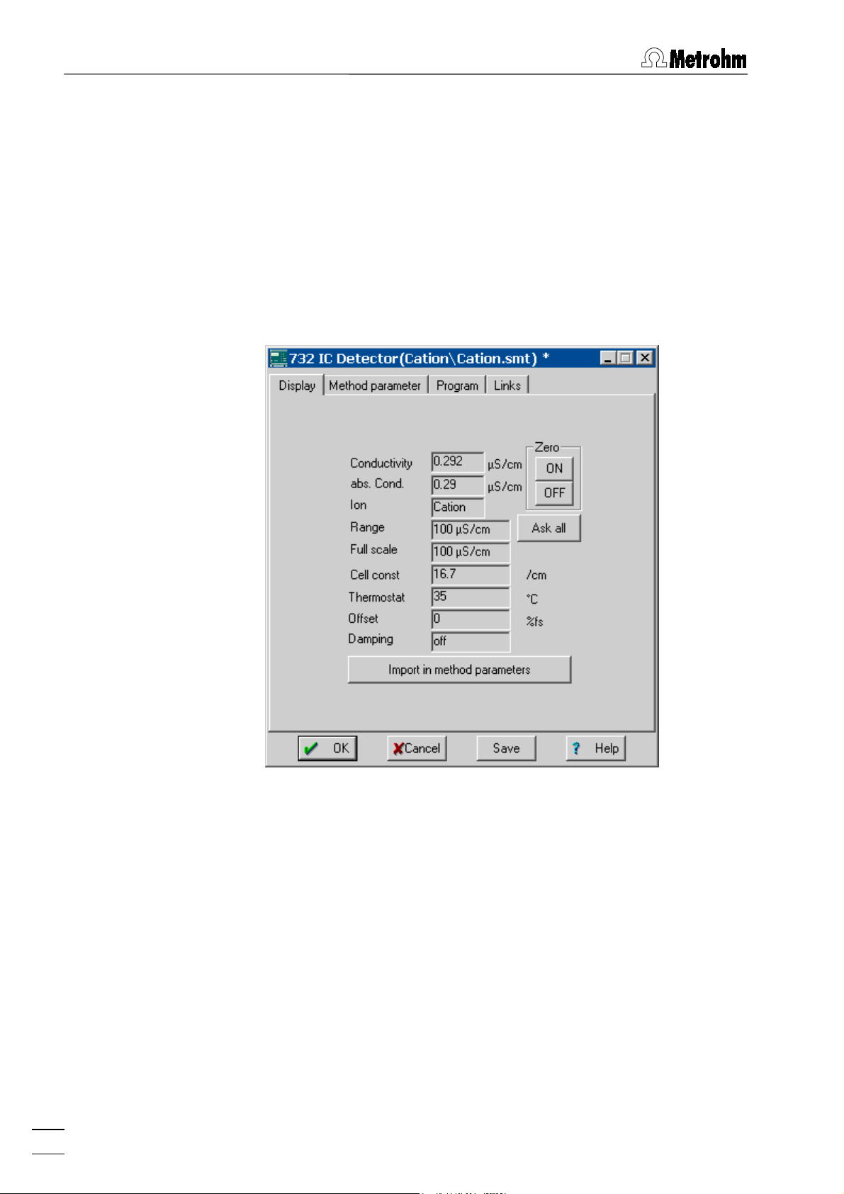
6 Devices
6.3.3 732 IC Detector window
732 icon / Open
The
732 IC Detector
selecting this menu option with the right mouse button or by double-clicking the
four tabs
Display, Method parameter, Program
Display
The
Display
tab of the
connected system. It displays the current measurement values
and parameters settings of the 732 IC Detector.
window for parameter settings is opened by
732 icon
in the
732 IC Detector
SYSTEM
window. It consists of the
, and
Links
.
window is only available for a
50
Conductivity
Live display of measured conductivity
(auto-zero value) in PS/cm. This field is
available for the
watch window color is changed to the
of range
color if the measured value is more
than 80% outside the
abs. Cond.
Live display of absolute conductivity value
in PS/cm. This field is available for the
WATCH WINDOW
changed to the
Out of range
measured value is bigger or equal to 110%
of
Range.
Display of ion settings:
Ion
Anion
Cation: polarity = –, temperature coeff. = 1.5
:
polarity = +, temperature coeff. = 2.5
WATCH WINDOW
Full Scale
. The
Out
range.
. The watch window color is
color if the
IC Net 2.1
Page 59

6.3 732 IC Detector
Range
Display of measuring range in PS/cm.
Full scale
Cell const
Display of full scale range in PS/cm.
. Display of cell constant of the conductivity
cell in /cm.
Thermostat
Display of temperature within in the detec-
tor block.
Display of offset of the zero point.
Offset
Damping
Display of electronic damping of the analog
output.
Zero <ON>
Zero <OFF>
<Ask all>
<Import in method parameters>
Triggers the auto-zero function.
Switch off the auto-zero function.
Update all display values.
Copy displayed parameters into the
parameter
tab.
Method
Method parameter
The
Method parameter
the method startup values for the instrument. These values are
sent and applied to the 732 IC Detector by
Startup hardware
tab of the
732 IC Detector
window contains
Start determination
, or if the values are sent manually with
<SET>
and
.
IC Net 2.1
51
Page 60

6 Devices
Range
Measuring range in PS/cm
Selection:
1, 2, 5, 10 mS/cm
100, 200, 500 PPPPS/cm
and
Full scale
The full scale range (operating range) sets
the desired sensitivity for the analog output.
The possible values of the full scale range
in PS/cm depend on the preset measuring
Range
Combination of polarity and temperature
Ion
.
coefficient:
Anion
Cation
Custom
Polarity
Temperature coeff.
independent selection of
Polarity
polarity = +, temperature coeff. = 2.5
polarity = –, temperature coeff. = 1.5
polarity
perature coeff.
of the analog output signal:
positive polarity (e.g. for anions)
+
negative polarity (e.g. for cations)
–
and
Converts automatically the conductivity
from the operating temperature of the
measuring cell to the reference temperature
of 20° C.
Selection:
1.5, 2.5 %/°C
tem-
Cell constant
Thermostat
Offset of the zero point of the conductivity.
Offset
Damping
<SET>
Send current parameters immediately to the
For detailed information about the parameters of the 732 IC Detector see 732/733 Instructions for Use.
Time program
On the
time program for the remote output lines of the 732 IC Detector
can be entered. This program is started automatically as defined
in the
the determination is started (
moment the sample is injected (
Cell constant of the conductivity cell in /cm.
Entry range:
13 ... 21 /cm
Operating temperature of the conductivity
cell within in the detector block.
Selection:
Selection:
25, 30, 35, 40, 45 °C
0, 10, 50 %fs
and
off
Electronic damping of the analog output
Selection:
on, off
732 IC Detector. Parameters are not stored
in the system file (
) as long as the file is
*.smt
not saved.
Program
Start mode
tab of the
732 IC Detector
window (see section 4.4.3) either at the moment
Start with determination
Start with inject
window a user-defined
) or at the
).
52
IC Net 2.1
Page 61

6.3 732 IC Detector
Program
The
Program
Program
tab contains the two following subpages:
Main time program with all program
steps.
Remote configuration
Possibility for creation of user-defined
remote commands.
On the
Program
subpage, program steps including time, program
instruction and parameter can be entered.
First column
Time at which program instruction is ap-
plied.
Entry range:
0.0 ... 999.9 min
If no time is entered, the program instruction is applied together with the last instruction with time entry.
Second column
Program instruction (see below).
In addition to these predefined instructions,
user-defined remote commands can be entered if activated on the
tab.
tion
Remote configura-
IC Net 2.1
Third column
Parameter for program instruction (see be-
low).
ENABLED
Enable program start (a disabled program
is not started).
Will be executed by
<Add>
<Delete>
<Verify>
Add new program instruction.
Delete selected program instruction.
Test the time program (error messages are
Selection if the time program will be exe-
cuted by the PC or the
732 unit
.
displayed if program is wrong).
53
Page 62

6 Devices
List of program instructions
The following program instructions can be added to the time program on the
Instruction Parameter entry Meaning
Program
subpage:
Remote 0, 1, *
Flag reset, end
Range 100, 200, 5000 PPPPS/cm
1, 2, 5, 10 mS/cm
FS 0.05 PPPPS/cm ...
10 mS/cm
Set remote output lines 1...8 to
the desired values. For entry of
the first value, enter 1, 0 or *. For
entry of the other values, move
the cursor in front of the value to
be changed and enter 1, 0 or *.
Set program flag. The
end
flag
can be used to end a program,
especially if the program time
should be longer than the chromatogram
duration
. Additional
steps after this flag are not allowed. The
flag is used to
reset
reset the parameters to the system startup values.
Set measuring range to the selected value.
Set full scale range to the selected value (depends on
Range
setting).
Zero on, off
Polarity +, –
Mark
ValveA fill, inject
ValveB fill, inject
Suppressor
PumpRS on, off
Flow 0.01 ... 5 mL/min
Switch on or off the auto-zero
function.
Reset the polarity of the output
signal.
Trigger marking signal.
Switch injection valve A to "
or "
" position.
fill
Switch injection valve B to "
or "
" position.
fill
inject
inject
"
"
Switch suppressor module to the
next position.
Switch on or off the high-pressure
pump connected to the 732 IC
Detector.
Set flow rate of the high-pressure
pump to the desired value.
54
IC Net 2.1
Page 63

6.3 732 IC Detector
Pmax 0.0 ... 25.0 MPa
Set maximum pressure limit for
the high-pressure pump connected to the 732 IC Detector to
the desired value.
Pmin 0.0 ... 25.0 MPa
Set minimum pressure limit for the
high-pressure pump connected to
the 732 IC Detector to the desired
value.
Remote configuration
On the
Remote configuration
subtab user-defined remote commands can be defined, which can be inserted into a time program after being activated with
<Activate>
.
Links
Name (1st column)
Remote command (2nd column)
User-definable name of the remote com-
mand (e.g.
Start_766
Setting the remote output lines 1}8.
(line off, inactive, open)
0
(line on, active, 0 V)
1
(leave line in current status)
*
For entry of the first value, enter 1, 0 or *.
For entry of the other values, move the cursor in front of the value to be changed and
enter 1, 0 or *.
<Add>
<Delete>
<Activate>
Add new remote command.
Delete selected remote command.
Activate the defined remote commands for
insertion into the time program.
The
Links
tab of the
732 IC Detector
is used for COM port selection
and settings (details see section 5.2.4).
).
IC Net 2.1
55
Page 64

6 Devices
6.4 761 Compact IC
6.4.1 761 Compact IC features
The Metrohm 761 Compact IC is a PC-controlled system for ion
chromatographic analyses. The two following versions are available:
x 2.761.0010 Compact IC without suppressor module
x 2.761.0020 Compact IC with suppressor module
All the parts of the 761 Compact IC like injection valve, highpressure pump, conductivity detector, suppressor module and
peristaltic pump, are normally fully controlled by the «761 Com-
pact IC» program. However, the 761 Compact IC can also be
operated using the «IC Net» program. This program also enables
the operation of more than one 761 Compact IC with one PC.
The 761 Compact IC is normally connected to a PC COM port using the 6.2134.100 connecting cable.
For detailed information about the 761 Compact IC see 761 In-
structions for Use.
6.4.2 761 Compact IC icon
System disconnected System connected System connected
"INJECT"
Injection valve in
position
"FILL"
Injection valve in
position
56
The
761 icon
has been installed with the
Setup/New devices/Install new device
(see section 6.1.3). If the system is connected, the
is available in the system window if a
New system wizard
or by using the
option of the
761 Compact IC
SYSTEM
window
761 icon
con-
tains two buttons for manual control of the injection valve at the
761 Compact IC:
<Inject>
<Fill>
Switch the injection valve to the "Inject" position.
Switch the injection valve to the "Fill" position.
IC Net 2.1
Page 65

6.4 761 Compact IC
If the system is connected and the
761 icon
is clicked with the
right mouse button, the following menu appears:
Open the
Open
Hardware
Diagnostics
Unlink
Open the hardware settings window.
Delete the
6.4.3 761 Compact IC window
761 icon / Open
The
761 Compact IC
selecting this menu option with the right mouse button or by clicking the
Initial, Program, Configuration
761 icon
761 Compact IC
window for parameter
settings (this window can also be opened by
double-clicking the icon).
Open the diagnostics window (for service per-
sonal only).
761 icon
from the system.
window for parameter settings is opened by
on the toolbar. It consists of the five tabs
, and
Links
.
Control
,
Control
The
Control
tab of the
761 Compact IC
window is only available for
a connected system. It allows manual control of the 761
Compact IC functions and setting of startup values to be sent to
the instrument.
IC Net 2.1
57
Page 66

6 Devices
Conductivity, PPPPS/cm
Live display of measured conductivity.
Pressure, MPa
Live display of measured pressure.
The color settings for this two fields can be
changed by clicking the fields with the right
mouse button (see section 6.2.2).
Actual values
Flow, mL/min
Pressure max, MPa
Display of actual values.
Display of current flow rate of the highpressure pump.
Display of current maximum pressure limit
for high-pressure pump.
Pressure min, MPa
Display of current minimum pressure limit
for high-pressure pump.
Full scale, PPPPS/cm
Remote lines
Injection valve.
Valve
<Inject>
<Fill>
Suppressor
Switch injection valve to "INJECT" position.
Switch injection valve to "FILL" position
Suppressor module.
Display of current full scale range.
Display of current remote line settings.
<Step>
IC pump
<On>
<Off>
Peristaltic
<On>
<Off>
System startup values
Flow, mL/min
Switch the suppressor module to the next
High-pressure pump.
Start high-pressure pump.
Stop high-pressure pump.
Peristaltic pump.
Start peristaltic pump.
Stop peristaltic pump.
position. The time since the last switching
of the suppressor module is displayed in
the field beside the
<Step>
button.
The system startup values are sent and ap-
plied to the 761 Compact IC each time the
system is connected, a determination is
started, or the values are sent manually with
<Send to unit>
.
Startup value for flow rate of the highpressure pump.
Entry range:
0.20
...
2.50 mL/min
58
Pressure max, MPa
Pressure min, MPa
Startup value for maximum pressure limit
for high-pressure pump. This limit is controlled even without connection to the PC.
Entry range:
0.0
...
25.0 MPa
Startup value for minimum pressure limit for
high-pressure pump. This limit is controlled
IC Net 2.1
Page 67

6.4 761 Compact IC
even without connection to the PC.
Entry range:
0.0
...
25.0 MPa
Initial
Full scale, PPPPS/cm
Remote lines
The
Initial
tab of the
Startup value for full scale range.
Selection: 50,
250, 1000 PPPPS/cm
Startup value for remote line settings 1}8.
Selection: 0,
761 Compact IC
1
window for settings of system
startup values is only available for a disconnected system.
Flow, mL/min
Pressure max, MPa
Pressure min, MPa
Full scale, PPPPS/cm
Remote lines
Time program
On the
time program for the remote output lines of the 761 Compact IC
can be entered. This program is started automatically as defined
in the
the determination is started (
moment the sample is injected (
Program
Start mode
Startup value for flow rate of the highpressure pump.
Entry range:
0.20
...
2.50 mL/min
Startup value for maximum pressure limit
for high-pressure pump.
Entry range:
0.0
...
25.0 MPa
Startup value for minimum pressure limit for
high-pressure pump.
Entry range:
0.0
...
25.0 MPa
Startup value for full scale range.
Selection: 50,
250, 1000 PPPPS/cm
Startup value for remote line settings 1}8.
Selection: 0,
tab of the
761 Compact IC
1
window a user-defined
window (see section 4.4.3) either at the moment
Start with determination
Start with inject
) or at the
).
IC Net 2.1
59
Page 68

6 Devices
Program
The
Program
Program
tab contains the two following subpages:
Main time program with all program
steps.
Remote configuration
Possibility for creation of user-defined
remote commands.
On the
Program
subpage, program steps including time, program
instruction and parameter can be entered.
First column
Time at which program instruction is ap-
plied.
Entry range:
0.0 ... 999.9 min
If no time is entered, the program instruction is applied together with the last instruction with time entry.
60
Second column
Third column
ENABLED
<Add>
<Delete>
<Verify>
Add new program instruction.
Parameter for program instruction (see be-
Delete selected program instruction.
Test the time program (error messages are
Program instruction (see below).
In addition to these predefined instructions,
user-defined remote commands can be entered if activated on the
tab.
tion
Remote configura-
low).
Enable program start (a disabled program
is not started).
displayed if program is wrong).
IC Net 2.1
Page 69

6.4 761 Compact IC
List of program instructions
The following program instructions can be added to the time program on the
Instruction Parameter entry Meaning
Program
subpage:
Valve Inject, Fill
FullScale 50, 250, 1000
PPPPS/cm
ICPump on, off
Flow 0.2 ... 2.5 mL/min
Pmax 0.0 ... 25.0 MPa
Pmin 0.0 ... 25.0 MPa
Remote 0, 1, *, p
Switch injection valve to "INJECT"
or "FILL" position.
Set full scale range to the selected value.
Switch on or off the high-pressure
pump.
Set flow rate of the high-pressure
pump to the desired value.
Set maximum pressure limit for
the high-pressure pump to the desired value.
Set minimum pressure limit for
the high-pressure pump to the desired value.
Set remote output lines 1...8 to
the desired values. For entry of the
first value, enter 1, 0, p or *. For entry of the other values, move the
cursor in front of the value to be
changed and enter 1, 0, p or *.
Program END, RESET
The
flag can be used to end a
END
program, especially if the program
time should be longer than the
chromatogram duration. Additional
steps after this flag are not allowed.
The
RESET
flag is used to reset the
parameters to the system startup
values.
Suppressor
Switch suppressor module to the
next position.
Peristaltic on, off
Switch on or off the peristaltic
pump.
Remote configuration
On the
Remote configuration
subtab user-defined remote commands can be defined, which can be inserted into a time program after being activated with
<Activate>
.
IC Net 2.1
61
Page 70

6 Devices
Name (1st column)
Remote command (2nd column)
<Add>
<Delete>
<Activate>
Configuration
The
Configuration
figuration settings for the 761 Compact IC.
User-definable name of the remote com-
mand (e.g.
Start_766
).
Setting the remote output lines 1}8.
(line off, inactive, open)
0
(line on, active, 0 V)
1
(pulse)
p
(leave line in current status)
*
For entry of the first value, enter 1, 0, p or *.
For entry of the other values, move the cursor in front of the value to be changed and
enter 1, 0, p or *.
Add new remote command.
Delete selected remote command.
Activate the defined remote commands for
insertion into the time program.
tab in the system settings window contains con-
62
IC Net 2.1
Page 71

6.4 761 Compact IC
761 unit version
Selection of instrument version:
761.0010
= 761 Compact IC without sup-
pressor
761.0020
= 761 Compact IC with suppres-
sor
Links
Suppressor
Autostep with
Suppressor module:
Automatic switching to the next position
each time the injection valve is switched ei-
Use peristaltic pump
ther to the
If this option is disabled, the peristaltic
or to the
Fill
pump is not switched on automatically at
the start of a determination or with
Polarity
Measure channel
The
Selection of the output signal polarity:
tab of the
Links
hardware
positive polarity (for anions)
+
negative polarity (for cations)
–
Display of the data source selected in the
Data source
761 Compact IC
.
window (see section 6.16.2).
is used for COM port selection
and settings (details see section 5.2.4).
Inject
position.
Startup
6.4.4 Hardware settings
Selection of the
mouse button opens the hardware settings window consisting of
the three tabs
Hardware
The
Hardware
eral parameters which are set automatically at power on of the
761 Compact IC.
Hardware
Hardware, Outputs
menu item of the
and
761 icon
Alarm stops
using the right
.
tab of the hardware settings window defines gen-
IC Net 2.1
63
Page 72

6 Devices
Remote lines after power on
The remote output lines 1}8 are set to this
values after power on or a manual stop with
Shutdown hardware
Selection: 0, 1
.
Thermostat
Operating temperature of the conductivity
Thermostatting functions only if the ambient temperature is at least 5 °C lower than the operating temperature. It normally takes 30}60 min after power on until
a temperature stability of r 0.01 °C is attained.
Flow correction
Cell constant
Cell constant of the conductivity cell for cor-
cell.
Selection: 25, 30, 35, 40,
45 °C, off
Factor for correction of the difference be-
tween displayed and actual flow rate of the
high-pressure pump.
Range:
0.9
...
1.09
The flow correction is determined by measurement of the actual flow rate with the aid
of a measuring cylinder as follows:
Displayed flow rate
Flow correction
=
Measured flow rate
rect display of the absolute conductivity.
Enter the cell constant printed on the detector block into this field.
Range:
0.1
...
99.9 /cm
For a precise determination of the cell constant, pump a calibration solution of known
conductivity through the IC system, observe
the displayed conductivity and change the
cell constant until the correct conductivity
value is displayed.
<Break times>
Possibility for changing the break times for
injection valve
ule
Suppressor
and suppressor mod-
Valve
.
These values should only be changed after consulting the Metrohm Service.
64
IC Net 2.1
Page 73

6.4 761 Compact IC
Outputs
The
Outputs
tab of the hardware settings window defines remote
output signals to be set automatically if specific events occur.
Events for automatic remote signal output:
Event
Switching of the injection valve to the "IN-
Inject
JECT" position.
Switching of the injection valve to the "FILL"
Fill
Suppressor step
position.
Switching of the suppressor module to the
next position.
Pump stop (P max/min)
Pump stopped because pressure limits are
Hardware error
exceeded.
Hardware error detected at the 761 Com-
pact IC (high-pressure pump, injection
valve, or suppressor not working correctly).
Alarm leak detector
Remote line
Set remote output lines 1}8.
Leak detector has detected solvent in the
instruments interior.
Selection: 0 (line off, inactive, open)
(line on, active, 0 V)
1
(pulse output)
p
(leave line in current status)
*
IC Net 2.1
PowerOn values
Pulse length
Display of the power on startup values for
remote output lines set on the
Hardware
Length of a pulse in ms.
tab.
65
Page 74

6 Devices
Alarm stops
The
events for which the 761 Compact IC is stopped immediately. At
an alarm stop, high-pressure pump and peristaltic pump are
stopped immediately, the running determination and the active
sample queue are also stopped.
Alarm stops
tab of the hardware settings window defines the
Events for alarm stop:
Event
Pump stop
Pump stopped because pressure limits are
exceeded.
Hardware error
Hardware error detected at the 761 Com-
pact IC (high-pressure pump, injection
valve, or suppressor not working correctly).
Leak detector has detected solvent in the
Leak
instruments interior. This information is also
stored in the instrument itself, so that it is
stopped automatically even without connection to the PC.
Power on
Temporary power failure at the 761 Com-
pact IC hardware.
66
IC Net 2.1
Page 75

6.5 817 Bioscan
6.5 817 Bioscan
6.5.1 817 Bioscan features
The Metrohm 817 Bioscan is a pulsed amperometric detector for
use with a modular IC system. The instrument is designed to
carry out determination of carbohydrates but is also capable of
analyzing alcohols (polyalcohols), sugar alcohols, as well as other
oxidizable substances.
The 817 Bioscan is fully operated using the «IC Net» program. It
is normally connected directly to a PC COM port using the
6.2134.080 or 6.2134.090 cable and the 6.2125.150 Adaptor.
For detailed information about the 817 Bioscan see 817 Instruc-
tions for Use.
6.5.2 817 Bioscan icon
The
817 icon
been installed with the
Setup/New devices/Install new device
(see section 6.1.2).
If the system is connected and the
right mouse button, the following menu appears:
Open the
Open
Unlink
Delete the
6.5.3 817 Bioscan window
817 icon / Open
The
817 Bioscan
lecting this menu option with the right mouse button or by doubleclicking the
tabs
Manual, Method parameters, Program
is available in the system window if a
New system wizard
817 Bioscan
window for parameter settings
or by using the
option of the
817 icon
is clicked with the
SYSTEM
817 Bioscan
has
window
(this window can also be opened by double-clicking
the icon).
817 icon
from the system.
window for parameter settings is opened by se-
817 icon
in the
SYSTEM
window. It consists of the four
, and
Links
.
IC Net 2.1
Manual
The
Manual
tab of the
817 Bioscan
window is only available for a
connected system.
67
Page 76

6 Devices
Mode
DC
Pulse
Scan
Cell
<On>
<Off>
Oven
Selection of detector mode:
In DC mode, a constant potential is applied
to the working electrode, the analytes are
oxidized or reduced in accordance with
their electrochemical properties.
The
mode works with three different
Pulse
working potentials, which are applied cyclically. This frees the electrode surface from
any adhering reaction products after each
sweep and an activated surface is produced for the next measurement.
The
mode allows potential/current
Scan
curves to be recorded.
Manual control of amperometric detector
cell:
Switch on detector cell.
Switch off detector cell.
Manual control of column oven (heater):
68
<On>
<Off>
Temperature
Control
<Set>
Aux1, Aux2, Cont1, Cont2
Switch on oven.
Switch off oven.
Temperature of column oven.
Range:
15 ... 60 °C
Manual setting of 4 control lines.
Set control lines to selected states.
Setting of 4 control lines.
Selection: 0, 1, *
IC Net 2.1
Page 77

6.5 817 Bioscan
Valve
<Fill>
<Inject>
Analog output
<Zero>
Actual
Mode
Cell
Oven
Control
Manual switching of the injection valve at
the 812 Valve Unit:
Switch injection valve to "Fill" position (control line
Cont1
is set to 0).
Switch injection valve to "Inject" position
(control line
Cont1
is set to 1).
Manual setting of the analog output signal
to zero.
Trigger the autozero function.
Display of actual values.
Display of current detector mode.
Display of current cell state.
Display of current ovent state.
Display of current control line settings.
DC mode
The
DC mode
window is used to set the parameters for the DC mode. This
scan
window is only available if
subtab of the
Method parameters
has been set to DC on the
Mode
tab on the
tab.
817 Bio-
Manual
IC Net 2.1
Method data
Cell potential
Electric potential applied to the amperomet-
ric detector cell in V
Range:
-2 ... +2 V
.
69
Page 78

6 Devices
Switching on/off column oven and setting
Oven
operating temperature.
Range:
15 ... 60 °C
Range
Full scale
Electronic damping of the analog output
Filter
Offset
Actual
Cell potential
Display of current oven state.
Oven
Range
Full scale
Selection of measuring range:
pA 10 ... 5000 pA
nA 0.1 ... 50 nA
µA 0.01 ... 5 µA
.
.
.
The full scale range (operating range) sets
the desired sensitivity for the analog output.
The possible values of the full scale range
depend on the preset measuring
Range
.
signal.
Selection:
0.1, 0.2, 0.5, 1, 2, 5 s
Offset of the zero point for the analog out-
put signal.
Selection:
-50 ... +50 %
(in steps of 10 %)
Display of current cell potential in V
Display of current measuring range.
Display of current full scale range.
Filter
Offset
<Set>
Pulse mode
The
Bioscan
This window is only available if
Manual
Method data
Cell
Display of current damping constant.
Display of current offset.
Send current parameters immediately to the
817 Bioscan. Parameters are not stored in
the system file (
) as long as the file is
*.smt
not saved.
Pulse mode
subtab of the
Method parameters
tab on the
817
window is used to set the parameters for the pulse mode.
has been set to
Mode
Pulse
on the
tab.
Definition of three different working poten-
tials, which are applied to the amperometric
detector cell cyclically. The set potentials
are graphically displayed if the
Method
op-
tion is enabled above the graphic window.
70
E1, E2, E3
t1, t2, t3
Working potentials.
Range:
-2 ... +2 V
.
Time duration to apply the working potential.
Range:
0.01 ... 2 s
IC Net 2.1
Page 79

6.5 817 Bioscan
Sample time
Oven
Range
Full scale
Offset
Actual
Measuring time at the end of working po-
tential E1.
Selection:
20, 40, 60, 80, 100 ms
Switching on/off column oven and setting
operating temperature.
Range:
15 ... 60 °C
Selection of measuring range:
pA 10 ... 5000 pA
nA 0.1 ... 50 nA
µA 0.01 ... 5 µA
.
.
.
The full scale range (operating range) sets
the desired sensitivity for the analog output.
The possible values of the full scale range
depend on the preset measuring
Range
.
Offset of the zero point for the analog out-
put signal.
Selection:
-50 ... +50 %
(in steps of 10 %)
IC Net 2.1
E1, E2, E3
t1, t2, t3
Display of current working potentials in V.
Display of current time durations for work-
ing potentials in s.
Sample time
Display of current sample time in ms.
71
Page 80

6 Devices
Display of current oven state.
Oven
Cycle potentials
<Set>
Scan mode
The
Bioscan
for the scan mode. This window is only available if
set to
Range
Full scale
Offset
Display of current measuring range.
Display of current full scale range.
Display of current offset.
Graphical display of cycle potentials.
Method
Display of working potentials set in the
Method data frame.
Actual
Display of current working potentials.
Send current parameters immediately to the
817 Bioscan. Parameters are not stored in
the system file (
) as long as the file is
*.smt
not saved.
Scan mode
subtab of the
Method parameters
tab on the
817
window is used for parameter setting and curve display
has been
Mode
Scan
on the
Manual
tab.
Parameters
72
IC Net 2.1
Page 81

6.5 817 Bioscan
Method data
Cell potential
Definition of start and end potential for a
user-defined potential sweep, which is applied to the amperometric detector cell.
E1
E2
Scan cycle
Scan rate
Oven
Definition of scan cycle:
Definition of scan rate in mV/s.
Switching on/off column oven and setting
Start potential for sweep.
Range:
-2 ... +2 V
.
End potential for sweep.
Range:
Selection:
Selection:
-2 ... +2 V
double scan
full
single scan
half
full, half
1, 2, 5, 10, 20, 50 mV/s
.
E1 ... E2 ... E1
E1 ... E2
operating temperature.
Range
Range:
15 ... 60 °C
Selection of measuring range:
pA 10 ... 5000 pA
nA 0.1 ... 50 nA
µA 0.01 ... 5 µA
.
.
.
Full scale
The full scale range (operating range) sets
the desired sensitivity for the analog output.
The possible values of the full scale range
depend on the preset measuring
Offset of the zero point for the analog out-
Offset
put signal.
Actual
E1, E2
Selection:
-50 ... +50 %
Display of current start and end potentials
(in steps of 10 %)
in V.
Scan cycle
Scan rate
Oven
Range
Full scale
Offset
Send current parameters immediately to the
<Set>
Display of current scan cycle mode.
Display of current scan rate in mV/s.
Display of current oven state.
Display of current measuring range.
Display of current full scale range.
Display of current offset.
817 Bioscan. Parameters are not stored in
the system file (
) as long as the file is
*.smt
not saved.
Range
.
IC Net 2.1
73
Page 82

6 Devices
Operations
Links
Caption
Possibility to enter a title which is written on
top of the scan mode graphics window
<Add date & time>
The current date and time are added to the
title defined in the
State
<Start>
<Stop>
<Copy to clipboard>
Display of current state.
Start scan mode sweep.
Stop scan mode sweep.
Copy the content of the scan mode graph-
ics window to the clipboard.
The
Links
tab of the
817 Bioscan
is used for COM port selection
and settings (details see section 5.2.4).
Caption
.
field.
74
IC Net 2.1
Page 83

6.6 733 IC Separation Center
6.6 733 IC Separation Center
6.6.1 733 IC Separation Center features
The Metrohm 733 IC Separation Center is a thermally and electronically isolated wet part which accommodates injectors, columns, detectors, suppressor module and pulsation dampener
and is controlled by and connected to the 732 IC Detector. The
following versions are available:
x 2.733.0010 IC Separation Center with 1 injector
x 2.733.0020 IC Separation Center with 2 injectors
x 2.733.0120 IC Separation Center with 2 injectors, metal-free
x 2.733.0030 IC Separation Center with 1 injector and 1 sup-
pressor module
x 2.733.0130 IC Separation Center with 1 injector and 1 sup-
pressor module, metal-free
The 733 IC Separation Center, which is normally operated by the
732 IC Detector, can be fully operated using the «IC Net» program. The 733 IC Separation Center with one injection valve is
normally connected to the 732 IC Detector using the 6.2125.090
cable. For the operation of a 733 IC Separation Center with two
independent columns and two injection valves, two individual
732 IC Detectors are needed. Each of this detectors is connected
to the 733 IC Separation Center using a 6.2125.090 cable. For
operation of a two-valve system with «IC Net», two
two
733 icons
stalled in the
(one for valve A and one for valve B) have to be in-
SYSTEM
window.
732 icons
and
For detailed information about the 733 IC Separation Center see
732/733 Instructions for Use. Examples for interconnections
with the 733 IC Separation Center, the 732 IC Detector and the
762 IC Interface can be found in the 762 Instructions for Use.
6.6.2 733 IC Separation Center icon
The
733 icon
tion Center
ing the
is available in the
has been installed with the
Setup/New devices/Install new device
window (see section 6.1.2).
SYSTEM
window if a
New system wizard
733 IC Separa-
option of the
or by us-
SYSTEM
IC Net 2.1
75
Page 84

6 Devices
If the system is connected and the
733 icon
is clicked with the
right mouse button, the following menu appears:
Open the
Open
733 IC Separation Center
ter settings (this window can also be opened by double-clicking the icon).
Unlink
Delete the
733 icon
6.6.3 733 IC Separation Center window
733 icon / Open
The
733 IC Separation Center
opened by selecting this menu option with the right mouse button
or by double-clicking the
sists of the two tabs
733 icon
IC733
IC733
The
IC733
tab of the
733 IC Separation Center
able for a connected system. The parameters and buttons for
manual operation depend on the type of instrument connected.
window for parame-
from the system.
window for parameter settings is
and
in the
Links
SYSTEM
.
window. It con-
window is only avail-
76
Configuration
valve A
valve A + valve B
valve A + suppressor
Valve A
fill/inject
<FILL>
<INJECT>
Valve B
fill/inject
<FILL>
<INJECT>
733 IC Separation Center with 1 injector.
Display of current valve position.
Switch valve A to "fill" position.
Switch valve A to "inject" position.
Display of current valve position.
Switch valve B to "fill" position.
Switch valve B to "inject" position.
Display of current instrument configuration.
733 IC Separation Center with 2 injectors.
733 IC Separation Center with 1 injector
and 1 suppressor module.
IC Net 2.1
Page 85

6.7 709 IC Pump
Suppressor
in position
<STEP>
Auto Step
fill, inject, off
Entry field
Switch suppressor module to next position.
Links
The
Links
tab of the
selection and settings (details see section 5.2.4).
6.7 709 IC Pump
6.7.1 709 IC Pump features
The Metrohm 709 IC Pump is a serial dual piston high pressure
pump for ion chromatography. The two following versions are
available:
Display of current suppressor status.
Display of current auto step status.
Set automatic switching of the suppressor
module after each "fill" or "inject" of valve A.
Selection:
733 IC Separation Center
fill, inject, off
is used for COM port
x 2.709.0010 IC Pump (standard version)
x 2.709.0110 IC Pump (metal-free version)
The 709 IC Pump, which is normally operated using the keypad of
the instrument or via 732 IC Detector, can be fully operated using
the «IC Net» program. It can be connected either to the 732 IC
Detector using the 6.2125.060 cable, to the 762 IC Interface using
the 6.2134.080 or 6.2134.090 cable, or to a PC COM port using
the 6.2134.040 or 6.2134.100 cable. If it is connected to the 732
IC Detector, the
Isocratic pump 709 for 732
device must be selected
for the installation of the 709 IC Pump in a system. If it is connected to the 762 IC Interface, the
Isocratic pump 709
device must
be selected for the installation of the 709 IC Pump in a system.
Examples for interconnections with the 709 IC Pump can be
found in the 762 Instructions for Use.
The cable connection between 709 IC Pump and 732 IC Detector, 762 IC Interface or PC must be made before switching on
the instrument. In order to operate the 709 IC Pump with «IC
Net», the external control must be switched on using the [ Ext. ]
key.
IC Net 2.1
For detailed information about the 709 IC Pump see 709 Instructions for Use.
77
Page 86

6 Devices
6.7.2 709 IC Pump icon
The
709 icon
or an
709
system wizard
option of the
If the system is connected and the
right mouse button, the following menu appears:
Open the
Open
Unlink
Delete the
6.7.3 709 IC Pump window
709 icon / Open
The
709 IC Pump
trol is opened by selecting this menu option with the right mouse
button or by double-clicking the
consists of the three tabs
is available in the
Isocratic pump 709 for 732
or by using the
SYSTEM
window (see section 6.1.2).
709 IC Pump
SYSTEM
Setup/New devices/Install new device
window for parameter settings
window if an
Isocratic pump
has been installed with the
709 icon
is clicked with the
(this window can also be opened by double-clicking
the icon).
709 icon
from the system.
window for parameter settings and manual con-
709 icon
Settings, Links
in the
and
Advanced
SYSTEM
window. It
.
New
Settings
The
Settings
tab of the
connected system.
709 IC Pump
window is only available for a
78
IC Net 2.1
Page 87

6.7 709 IC Pump
Pressure
Live display of current pressure in MPa.
This field is also available for the
WINDOW
.
WATCH
Flow
New flow
A new flow can be set by moving the scroll
Live display of current flow in mL/min. This
field is also available for the
DOW
.
WATCH WIN-
bar, by entering a value or by changing the
value using the up and down arrows.
Min/Max pressure
Entry range:
0.01 ... 5.00 mL/min
The minimum and maximum pressure limit
for the 709 IC Pump can be set in steps of
0.1 MPa.
Entry range:
0.0 ... 50.0 MPa
.
The set maximum limit value should lie be-
tween 5 to 10 MPa above the particular
operating pressure or the maximum admissible operating pressure of the column
used. If the pump exceeds the preset limit
value during operation, it is switched off
immediately. At the same time, the
Pressure
field color in the 709 settings window and in
the
WATCH WINDOW
value set for
Out of range
is changed to the
.
The set minimum limit value should lie far
enough below the particular operating
pressure. If the pump pressure falls below
this preset lower limit during operation and
this pressure drop persist for several revolutions of the pump cam due to leaks or interrupted inflow of the eluent, the pump is
automatically switched off. At the same
time, the
Pressure
tings window and in the
changed to the value set for
Send current parameters immediately to the
<Set>
field color in the 709 set-
WATCH WINDOW
Out of range
is
.
709 IC Pump (only available if pump is running). Parameters are not stored in the system file (
) as long as the file is not
*.smt
saved.
<Start>
Set current parameters and start 709 IC
Pump drive.
<Stop>
Stop 709 IC Pump drive.
IC Net 2.1
Links
The
Links
tab of the
709 IC Pump
is used for COM port selection
and settings (details see section 5.2.4).
79
Page 88

6 Devices
Advanced
The
connected system.
Advanced
tab of the
709 IC Pump
window is only available for a
Correction factor
Flow correction factor to adjust the dis-
played flow to the actual flow measured
with the aid of a measuring cylinder.
Entry range:
Read current
<Ask>
Send current
<Set>
709 IC Pump. This parameter is not stored
in the system file (
not saved.
6.8 Metrohm solvent delivery unit
0.90 ... 1.10
Correction factor
Correction factor
) as long as the file is
*.smt
value.
value to the
6.8.1 Metrohm SDU features
A Metrohm SDU (Solvent Delivery Unit) system can be used for
high-pressure gradient mixture of one to four eluents. For each
eluent, a 709 IC Pump is used. Each 709 IC Pump must be connected to the 762 IC Interface using a 6.2134.080 or 6.2134.090
cable. Examples for interconnections with the 709 IC Pump can
be found in the 762 Instructions for Use.
The outlet capillaries of the 709 IC Pumps must be connected to
a mixing chamber from where one inlet capillary leads to the injection valve of the 733 IC Separation Center.
For detailed information about the 709 IC Pump see 709 Instruc-
tions for Use.
80
IC Net 2.1
Page 89

6.8 Metrohm solvent delivery unit
6.8.2 Metrohm SDU icon
The
SDU icon
Delivery Unit) has been installed with the
using the
TEM
Setup/New devices/Install new device
window (see section 6.1.2). The
four 709 IC Pump icons one above the other depending on the
SDU type installed.
If the system is connected and the
right mouse button, the following menu appears:
Open the
Open
Unlink
Delete the
6.8.3 Metrohm SDU window
SDU icon / Open
The
Pump control system
ual control is opened by selecting this menu option with the right
mouse button or by double-clicking the
window. It consists of the four tabs
and
Links
.
is available in the
window for parameter settings (this
SDU
SYSTEM
window if an
New system wizard
icon consists of one to
SDU
SDU icon
(Solvent
SDU
or by
option of the
SYS-
is clicked with the
window can also be opened by double-clicking the
icon).
SDU icon
from the system.
window for parameter settings and man-
SDU icon
Manual, Program, Interfaces
in the
SYSTEM
,
Manual
The
Manual
tab of the
connected system.
Metrohm SDU
window is only available for a
IC Net 2.1
81
Page 90

6 Devices
Pressure
Live display of current pressure in MPa.
This field is also available for the
WINDOW
.
WATCH
Flow
New flow
A new flow can be set by moving the scroll
Live display of current flow in mL/min. This
field is also available for the
DOW
.
WATCH WIN-
bar, by entering a value or by changing the
value using the up and down arrows.
Entry range:
0.01 ... 20.00 mL/min
(depending
on number of pumps)
Min/Max pressure
The minimum and maximum pressure limit
for the individual pump units can be set in
steps of 0.1 MPa.
Entry range:
Individual flow rate for pump B in percent of
%B
0.0 ... 50.0 MPa
.
total flow.
Entry range:
Individual flow rate for pump C in percent of
%C
0 ... 100 %
total flow.
Entry range:
0 ... 100 %
Individual flow rate for pump D in percent of
%D
total flow.
Stop after
Time left
Entry range:
0 ... 100 %
Stop time for all pump drives.
Entry range:
0 ... 99999 min
Display of time left before pumps are
stopped.
Send current parameters immediately to the
<Set>
pump control system. Parameters are not
stored in the system file (
) as long as
*.smt
the file is not saved.
<Start>
<Stop>
Start all pump drives.
Stop all pump drives.
82
IC Net 2.1
Page 91

6.8 Metrohm solvent delivery unit
Program
The
Program
tab of the
window contains a time program for
SDU
the pump control system to define eluent gradients.
Flow
Stop pumps after the run
Program table
Number
Time at which the flow and/or gradient is
Time
Flow
Individual flow rate for pump B in percent of
%B
Individual flow rate for pump C in percent of
%C
Individual flow rate for pump D in percent of
%D
Row number in the program table (read-
Overall flow of pump control system in
mL/min. This value is also available for the
WATCH WINDOW
if the
Show flow column
Entry range:
. This field is only available
option is disabled.
0.01 ... 20.00 mL/min
(depending
on number of pumps)
Stop pumps after the determination.
only).
changed.
Entry range:
0.0 ... 99999 min
Overall flow of pump control system in
mL/min.
Entry range:
0.01 ... 20.00 mL/min
(depending
on number of pumps)
total flow.
Entry range:
0 ... 100 %
total flow.
Entry range:
0 ... 100 %
total flow.
Entry range:
0 ... 100 %
IC Net 2.1
83
Page 92

6 Devices
Enabled
Show flow column
<Add>
<Delete>
<Start>
Interfaces
The
nected system.
Enable time program start (a disabled pro-
gram is not started).
Show
column in the program table.
Flow
Add a new line to the time program.
Delete the selected line from the time pro-
gram.
Start all pump drives.
Interfaces
tab of the
window is only available for a con-
SDU
84
Links
Number of eluents
Pumps
List of used pumps for gradient mixing.
Number of eluents used for gradient mixing.
Clicking on
709 IC Pump
<A>, <B>, <C>
window for parameter settings
and manual control of the selected pump.
Pressure checking
Selection of the pump whose pressure is
checked using the
Time reaction for press. min/max overflow
Time delay for pump stopping at
pressure
limits.
The
Links
tab of the
Metrohm SDU
is used for COM port selection
and settings (details see section 5.2.4).
, or
<D>
Min/Max pressure
opens the
limits.
Min/Max
IC Net 2.1
Page 93

6.7 752 Pump Unit
6.7 752 Pump Unit
6.7.1 752 Pump Unit features
The Metrohm 752 Pump Unit is a 2-channel peristaltic pump
which is normally used for operating the suppressor module in
the 733 IC Separation Center by supplying regeneration and rinsing solutions.
The 752 Pump Unit, which is normally operated manually using
the keypad of the instrument or automatically via 732 IC Detector
via remote interface, can be fully operated using the «IC Net»
program. The 752 Pump Unit is normally connected to one of the
event line connections of the 762 IC Interface using the optional
6.2128.180 cable. Examples for interconnections with the 752
Pump Unit can be found in the 762 Instructions for Use.
In order to operate the 752 Pump Unit with «IC Net», the external
control must be switched on using the [ Remote ] key.
For detailed information about the 752 Pump Unit see 752 Instructions for Use.
6.7.2 752 Pump Unit icon
The
752 icon
has been installed with the
Setup/New devices/Install new device
(see section 6.1.2).
If the system is connected and the
right mouse button, the following menu appears:
Open the
Open
Unlink
Delete the
is available in the
New system wizard
752 Pump Unit
SYSTEM
window if a
752 Pump Unit
or by using the
option of the
752 icon
is clicked with the
SYSTEM
window
window for parameter settings
(this window can also be opened by double-clicking
the icon).
752 icon
from the system.
6.7.3 752 Pump Unit window
752 icon / Open
The
752 Pump Unit
selecting this menu option with the right mouse button or by double-clicking the
IC Net 2.1
three tabs
Manual, Program
window for parameter settings is opened by
752 icon
in the
, and
SYSTEM
Links
window. It consists of the
.
85
Page 94

6 Devices
Manual
The
Manual
tab of the
752 Pump Unit
window for manual operation
is only available for a connected system.
Pump
Start pump drive.
<On>
Stop pump drive.
<Off>
Start pump with startup hardware
Time program
On the
time program can be entered. This program is started automatically as defined in the
at the moment the determination is started (
) or at the moment the sample is injected (
tion
Program
Automatic start of pump drive with
hardware
tab of the
Start mode
.
752 Pump Unit
window (see section 4.4.3) either
Startup
window a user-defined
Start with determina-
Start with inject
).
86
First column
Second column
Third column
Time at which program instruction is ap-
Parameter for program instruction (see be-
plied.
Entry range:
0.0 ... 999.9 min
If no time is entered, the program instruction is applied together with the last instruction with time entry.
Program instruction (see below).
low).
IC Net 2.1
Page 95

6.7 752 Pump Unit
ENABLED
Enable program start (a disabled program
is not started).
<Add>
<Delete>
<Verify>
Add new program instruction.
Delete selected program instruction.
Test the time program (error messages are
displayed if program is wrong).
List of program instructions
The following program instructions can be added to the time program on the
Instruction Parameter entry Meaning
Program RESET, END
Program
page:
Set program flag. The
END
flag
can be used to end a program,
especially if the program time
should be longer than the chromatogram
duration
. Additional
steps after this flag are not allowed. The
RESET
flag is used to
reset the parameters to the system startup values.
Pump on, off
Switch on or off the pump drive.
Links
The
Links
tab of the
752 Pump Unit
is used for COM port selection
and settings (details see section 5.2.4).
IC Net 2.1
87
Page 96

6 Devices
6.8 753 Suppressor Module
6.8.1 753 Suppressor Module features
The Metrohm 753 Suppressor Module consists of a control unit
with a 2-channel peristaltic pump and a block containing a suppressor module.
The 753 Suppressor Module, which is normally operated manually using the keypad of the instrument or automatically via 732 IC
Detector via remote interface, can be fully operated using the «IC
Net» program. The 753 Suppressor Module is normally connected to two of the event line connections of the 762 IC Interface
using two optional 6.2128.180 cables. Examples for interconnections with the 753 Suppressor Module can be found in the 762
Instructions for Use.
In order to operate the 753 Suppressor Module with «IC Net»,
the external control must be switched on using the [ Remote ]
key.
For detailed information about the 753 Suppressor Module see
753 Instructions for Use.
6.8.2 753 Suppressor Module icon
The
753 icon
Module
the
Setup/New devices/Install new device
is available in the
has been installed with the
dow (see 6.1.2).
If the system is connected and the
right mouse button, the following menu appears:
Open the
Open
settings (this window can also be opened by doubleclicking the icon).
Unlink
Delete the
SYSTEM
window if a
New system wizard
option of the
753 icon
753 Suppressor Module
753 icon
from the system.
753 Suppressor
or by using
SYSTEM
win-
is clicked with the
window for parameter
6.8.3 753 Suppressor Module window
753 icon / Open
The
753 Suppressor Module
opened by selecting this menu option with the right mouse button
or by double-clicking the
sists of the three tabs
88
window for parameter settings is
753 icon
Manual, Program
in the
SYSTEM
, and
window. It con-
.
Links
IC Net 2.1
Page 97

6.8 753 Suppressor Module
Manual
The
Manual
tab of the
753 Suppressor Module
window for manual
operation is only available for a connected system.
Pump
Start pump drive.
<On>
Stop pump drive.
<Off>
Suppressor
<Step>
Start pump with startup hardware
Time program
On the
defined time program can be entered. This program is started
automatically as defined in the
ther at the moment the determination is started (
nation
) or at the moment the sample is injected (
Rotate suppressor to the next position. The
time since the last step action is displayed
in the field beside the
<Step>
button.
Program
Automatic start of pump drive with
hardware
tab of the
.
753 Suppressor Module
Start mode
window (see 4.4.3) ei-
window a user-
Start with determiStart with inject
Startup
).
IC Net 2.1
89
Page 98

6 Devices
First column
Time at which program instruction is ap-
plied.
Entry range:
0.0 ... 999.9 min
If no time is entered, the program instruction is applied together with the last instruction with time entry.
Second column
Third column
Program instruction (see below).
Parameter for program instruction (see be-
low).
ENABLED
Enable program start (a disabled program
is not started).
<Add>
<Delete>
<Verify>
Add new program instruction.
Delete selected program instruction.
Test the time program (error messages are
displayed if program is wrong).
List of program instructions
The following program instructions can be added to the time program on the
Instruction Parameter entry Meaning
Program RESET, END
Program
page:
Set program flag. The
END
flag
can be used to end a program,
especially if the program time
should be longer than the chromatogram
duration
. Additional
steps after this flag are not allowed. The
RESET
flag is used to
reset the parameters to the system startup values.
90
Pump on, off
Step
Switch on or off the pump drive.
Rotate suppressor to the next
position.
Links
The
Links
tab of the
753 Suppressor Module
is used for COM port
selection and settings (details see section 5.2.4).
IC Net 2.1
Page 99

6.9 754 Dialysis Unit
6.9 754 Dialysis Unit
6.9.1 754 Dialysis Unit features
The Metrohm 754 Dialysis Unit is a unit for on-line sample dialysis before sample injection. It consists of a 2-channel peristaltic
pump and a dialysis cell.
The 754 Dialysis Unit, which is normally operated manually using
the keypad of the instrument or automatically via 732 IC Detector
via remote interface, can be fully operated using the «IC Net»
program. The 754 Dialysis Unit is normally connected to one of
the event line connections of the 762 IC Interface using the optional 6.2128.180 cable. Examples for interconnections with the
754 Dialysis Unit can be found in the 762 Instructions for Use.
In order to operate the 754 Dialysis Unit with «IC Net», the external control must be switched on using the [ Remote ] key.
For detailed information about the 754 Dialysis Unit see 754 Instructions for Use.
6.9.2 754 Dialysis Unit icon
The
754 icon
has been installed with the
Unit
Setup/New devices/Install new device
(see section 6.1.2).
If the system is connected and the
right mouse button, the following menu appears:
Open the
Open
is available in the
754 Dialysis Unit
SYSTEM
New system wizard
window if a
754 Dialysis
or by using the
option of the
754 icon
is clicked with the
SYSTEM
window
window for parameter settings (this window can also be opened by doubleclicking the icon).
Unlink
Delete the
6.9.3 754 Dialysis Unit window
754 icon / Open
The
754 Dialysis Unit
selecting this menu option with the right mouse button or by double-clicking the
tabs
Manual, Program
IC Net 2.1
754 icon
from the system.
window for parameter settings is opened by
754 icon
, and
in
SYSTEM
Links
window. It consists of the three
.
91
Page 100

6 Devices
Manual
The
Manual
tab of the
754 Dialysis Unit
window for manual opera-
tion is only available for a connected system.
Pump
Start pump drive.
<On>
Stop pump drive.
<Off>
Start pump with startup hardware
Time program
On the
time program can be entered. This program is started automatically as defined in the
at the moment the determination is started (
) or at the moment the sample is injected (
tion
Program
Automatic start of pump drive with
hardware
tab of the
Start mode
.
754 Dialysis Unit
window (see section 4.4.3) either
Startup
window a user-defined
Start with determina-
Start with inject
).
92
First column
Second column
Time at which program instruction is ap-
plied.
Entry range:
0.0 ... 999.9 min
If no time is entered, the program instruction is applied together with the last instruction with time entry.
Program instruction (see below).
IC Net 2.1
 Loading...