

Page 1
IC Equipment Set
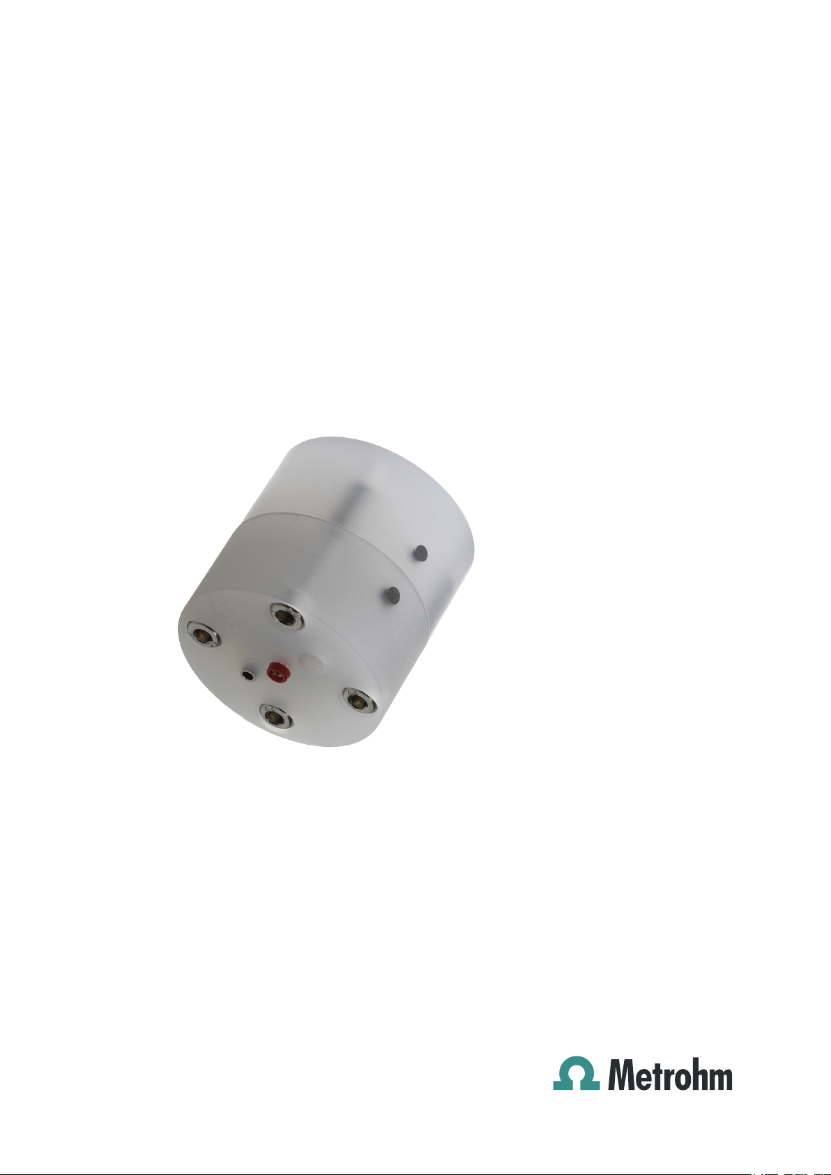
Flow Cell for Bioscan – 6.5331.0X0
Manual
8.110.8003EN
Page 2

Page 3

Metrohm AG
CH-9100 Herisau
Switzerland
Phone +41 71 353 85 85
Fax +41 71 353 89 01
info@metrohm.com
www.metrohm.com
IC Equipment Set
Flow Cell for Bioscan – 6.5331.0X0
Manual
8.110.8003EN 26.03.2008 zst
Page 4

Teachware
Metrohm AG
CH-9100 Herisau
teachware@metrohm.com
This documentation is protected by copyright. All rights reserved.
Although all the information given in this documentation has been
checked with great care, errors cannot be entirely excluded. Should you
notice any mistakes please send us your comments using the address
given above.
Documentation in additional languages can be found on
http://products.metrohm.com under Literature/Technical documenta-
tion.
Page 5

■■■■■■■■■■■■■■■■■■■■■■
Table of contents
1 Introduction 1
1.1 Description ............................................................................ 1
1.2 About the Documentation ................................................... 1
1.2.1 Symbols and conventions ........................................................ 1
2 Installation 3
3 Technical Data 6
3.1 General .................................................................................. 6
3.2 Gold flow cell ....................................................................... 6
3.3 Glassy Carbon flow cell ........................................................ 7
3.4 Platinum flow cell ................................................................. 7
3.5 Silver flow cell ....................................................................... 8
Table of contents
4 Accessories 9
4.1 Equipment set with Au flow cell for Bioscan ..................... 9
4.2 Equipment set with GC flow cell for Bioscan ................... 10
4.3 Equipment set with Pt flow cell of Bioscan ..................... 11
4.4 Equipment set with Ag flow cell for Bioscan ................... 13
Index 15
IC Equipment Set Flow Cell for Bioscan
■■■■■■■■
III
Page 6

Table of figures
Table of figures
Figure 1 Parts and connections of flow cell ..................................................... 3
■■■■■■■■■■■■■■■■■■■■■■
■■■■■■■■
IV
IC Equipment Set Flow Cell for Bioscan
Page 7
■■■■■■■■■■■■■■■■■■■■■■
1 Introduction
1.1 Description
The flow cell is used for amperometric detection with the Bioscan measuring instruments. The flow cell's construciton is based on the Wall-Jet-Principle. According to the Wall-Jet-Principle the inlet is positioned exactly
opposite to the working eleoctode, which allows for optimum measuring
perfomance.
The flow cell is available in four versions:
■ Gold flow cell (6.1254.010)
■ Glassy carbon flow cell (6.1254.050)
■ Platinum flow cell (6.1254.060)
■ Silver flow cell (6.1254.070)
For a more detailed description of the specification and intended use of
the individual cells, please see (see Chapter 3, page 6).
1 Introduction
1.2 About the Documentation
Caution
Please study this documentation carefully before you start to use the
instrument. The documentation contains information and warnings that
must be observed by the user in order to guarantee the safe use of the
instrument.
1.2.1 Symbols and conventions
The following symbols and styles are used in this documentation:
Cross-reference to figure legend
The first number refers to the figure number, the
second to the instrument part in the figure.
Instruction step
Carry out these steps in the sequence shown.
Warning
IC Equipment Set Flow Cell for Bioscan
This symbol draws attention to a possible life hazard
or risk of injury.
■■■■■■■■
1
Page 8

1.2 About the Documentation
■■■■■■■■■■■■■■■■■■■■■■
Warning
This symbol draws attention to a possible hazard due
to electrical current.
Warning
This symbol draws attention to a possible hazard due
to heat or hot instrument parts.
Warning
This symbol draws attention to a possible biological
hazard.
Caution
This symbol draws attention to a possible damage of
instruments or instrument parts.
Note
This symbol marks additional information and tips.
■■■■■■■■
2
IC Equipment Set Flow Cell for Bioscan
Page 9
■■■■■■■■■■■■■■■■■■■■■■
8
1
2
3
4
56
7
2 Installation
Never switch on the flow cell when it is..
■ ..not being rinsed through with a conducting eluent at the time; or
■ ..not completely connected; or
■ ..moist on the outside so that a short circuit could occur between
2 Installation
Caution
the connections of working eleoctrode and auxiliary electrode.
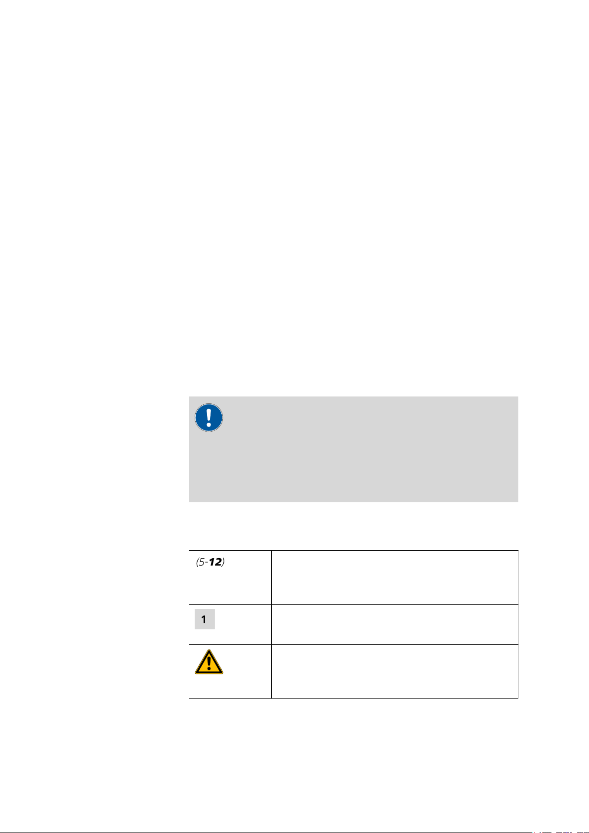
Figure 1 Parts and connections of flow cell
Reference electrode connection
1
For black electrode cable (6.2156.000).
Auxiliary electrode connection
3
For blue electrode cable (6.2156.000).
Outlet for eluent
5
Connection of PEEK capillary by 6.2744.130
KELF pressure screw only. PEEK pressure
screws may damage the threads of the cell.
7
Distance piece 50 µm (6.1254.020)
Defines the volume of the cell.
Inlet for eluent
2
Connection of PEEK capillary by 6.2744.130
KELF pressure screw only. PEEK pressure
screws may damage the threads of the cell.
Working eleoctrode connection
4
For red electrode cable (6.2156.000).
Mounting screws (4x)
6
Check marks
8
For correct alignment of the top and bottom
part of the flow-through cell.
IC Equipment Set Flow Cell for Bioscan
■■■■■■■■
3
Page 10

■■■■■■■■■■■■■■■■■■■■■■
Connect flow cell
1
Check mounting screws
Caution
Avoid overtightening the mounting screws (1-6), as this could
damage the distance piece (1-7)!
■ Use the provided hexagon key (6.2621.150) to loosen all four
mounting screws (1-6) by one rotation.
■ Then slighly tighten the screws again, e.g. by holding the hexagon
key between index finger and thumb only.
■ Finally, tighten all four mounting screws by a quarter rotation.
Always tighten opposing screws, i. e. tighten one screw antd then
its opposite.
2
Connect the electrode cable
■ Attach the electrode cable (6.2156.000 delivered with the 871
Advanced Bioscan) to the working electrode connection (1-4)
(red), the reference electrode connection (1-1) (black), and the
auxiliary electrode connection (1-3) (blue) of the flow cell.
■ Attach the other end to the connection for electrode cable of the
871 Advanced Bioscan.
3
Connect the separating column
■ Use a pressure screw (6.2744.130) to screw the column connec-
tion capillary of the separating column to the inlet for eluent
(1-2). Push the connection capillary into the inlet as far as it will
go (approx. 1.5 cm) and then fix it with the pressure screw (this
will prevent dead volume).
4
Connect waste tubing
■ To ensure sufficient back pressure, connect a PEEK capillary
(6.1831.010) of approx.1m length to the outlet for eluent (1-5).
Push the PEEK capillary into the outlet as far as it will go (approx.
0.5 cm) and then fix it with a pressure screw (6.2744.130) (this
will prevent dead volume).
■ Place the other end of the PEEK capillary into a waste container
and attach it.
■■■■■■■■
4
IC Equipment Set Flow Cell for Bioscan
Page 11

■■■■■■■■■■■■■■■■■■■■■■
5
Mount the flow cell
■ Attach the flow cell to the measuring cell holder of the Bioscan.
■ Rotate flow cell in its holder so that the outlet is located as high
as possible. This allows possibly occuring air bubbles to escape
from the cell.
2 Installation
IC Equipment Set Flow Cell for Bioscan
■■■■■■■■
5
Page 12

3.1 General
3 Technical Data
3.1 General
■■■■■■■■■■■■■■■■■■■■■■
Construction
Cell volume
Flow cell with working, reference and auxiliary electrode.
The cell volume depends on the thickness of the selected distance
piece:
Distance piece Cell volume
25 µM 0.15 µL
50 µM 0.29 µL
120 µM 0.71 µL
Working temperature
The flow cell should not be operated permanently at temperatures
higher than 45 °C.
Reference electrode
Type
Conversion to
Solid phase reference electrode
E
= E
Hy-REF
Ag/AgCl
3.2 Gold flow cell
- 328 + 29.9 pH (mV)
Ag/AgCl
Arbeitselektrode
Material
Durchmesser
Working electrode
Material
Diameter
Applications
Operating modes
Gold
3 mm
Gold
3 mm
Sugar and amino acids
■ mono-, di-, oligo- and polysaccharides
■ sugar alcohols
■ sugar amines
■ sugar acids
■ amino acids
■ antibiotics
DC and PAD
■■■■■■■■
6
IC Equipment Set Flow Cell for Bioscan
Page 13

■■■■■■■■■■■■■■■■■■■■■■
Operating range
Acidic medium
Alkaline
-0.35 V…+1.1 V
-1.25 V…+0.75 V
medium
3.3 Glassy Carbon flow cell
Working electrode
Material
Diameter
Glassy-Carbon
3 mm
3 Technical Data
Applications
Operating modes
Aromatics and amines
■ catecholamines, aromatic amines
■ inorganic anions (nitrite, sulfite ...)
■ phenols
■ vitamins
■ few amino acids
DC only (not PAD)
Operating range
Acidic medium
Alkaline
-0.8 V… +1.3 V
-1.5 V… +0.6 V
medium
3.4 Platinum flow cell
Working electrode
Material
Diameter
Applications
Platinum
3 mm
Special applications
■ alcohols
■ glycols
■ hydrogen peroxide
■ hydrazine
■ arsenite, hypochlorite
Operating modes
DC and PAD
Operating range
Acidic medium
Alkaline
-0.2 V… +1.3 V
-0.9 V… +0.65 V
medium
IC Equipment Set Flow Cell for Bioscan
■■■■■■■■
7
Page 14

3.5 Silver flow cell
3.5 Silver flow cell
Working electrode
Material
Diameter
Silver
2 mm
■■■■■■■■■■■■■■■■■■■■■■
Applications
Operating modes
Operating range
Acidic medium
Alkaline
medium
Environmental applications
■ halides
■ cyanide, sulfide
■ thiosulfate
■ pharmaceuticals
DC and PAD
-0.55 V… +0.4 V
-1.2 V… +0.1 V
■■■■■■■■
8
IC Equipment Set Flow Cell for Bioscan
Page 15

■■■■■■■■■■■■■■■■■■■■■■
4 Accessories
4.1 Equipment set with Au flow cell for Bioscan
6.5331.010 IC Equipment Set with Gold flow cell
Qty. Order no. Description
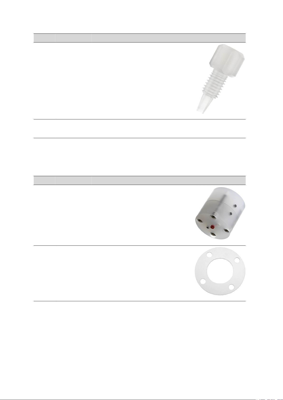
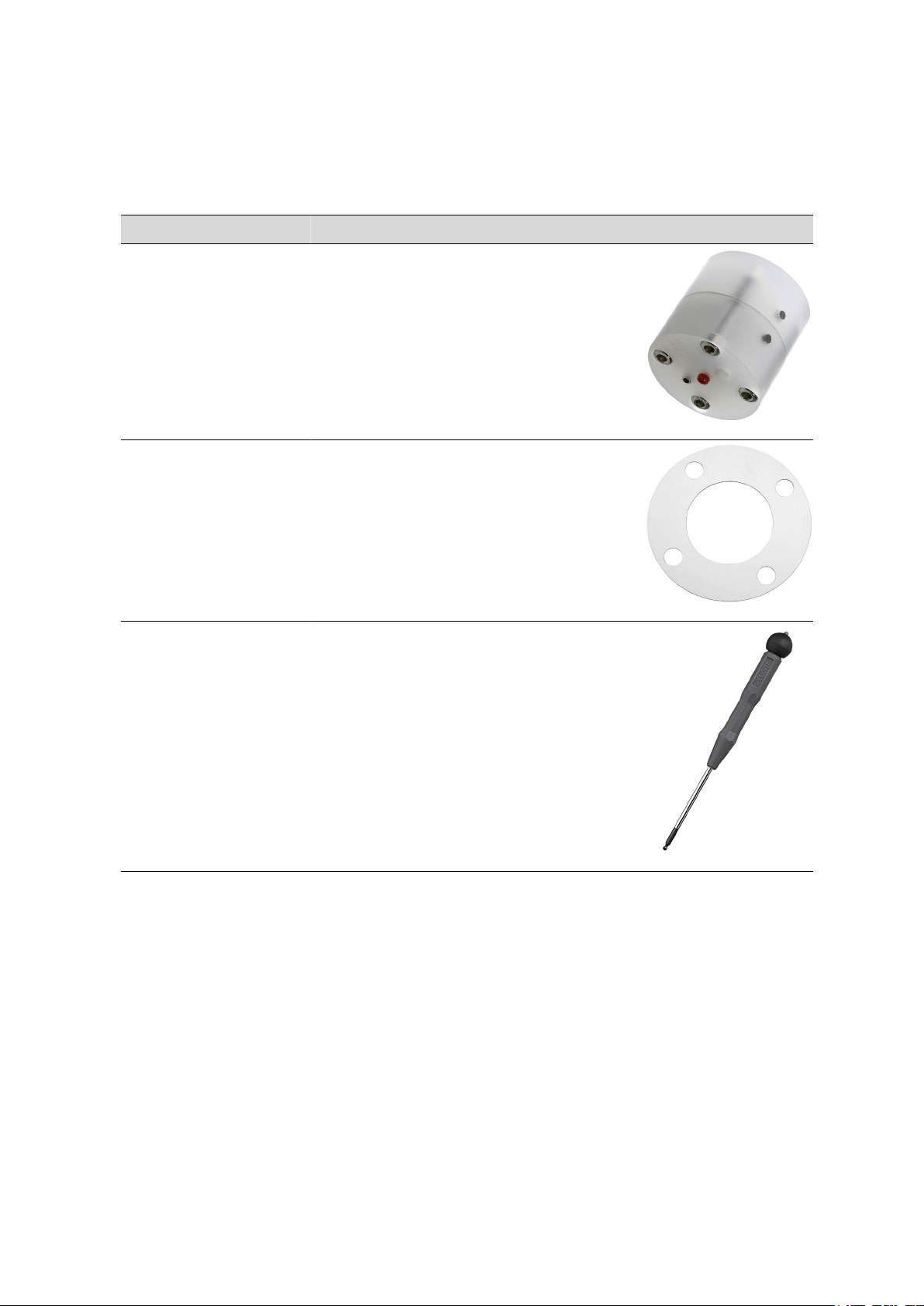
1 6.1254.010 Gold flow cell for Bioscan
Flow-through cell for Bioscan, electrode material: gold
Material: Gold
Material remark: Working electrode
4 Accessories
1 6.1254.020 Distance piece for Bioscan flow cell, 50 µm
50 µm Spacer for Bioscan flow-through cell
Material: Plastic
Height (mm): 0.05
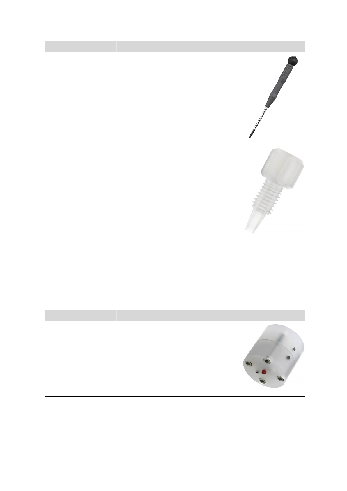
1 6.2621.150 Hexagon key 3 mm for Bioscan
Hexagon key 3 mm for Bioscan
IC Equipment Set Flow Cell for Bioscan
■■■■■■■■
9
Page 16
4.2 Equipment set with GC flow cell for Bioscan
Qty. Order no. Description
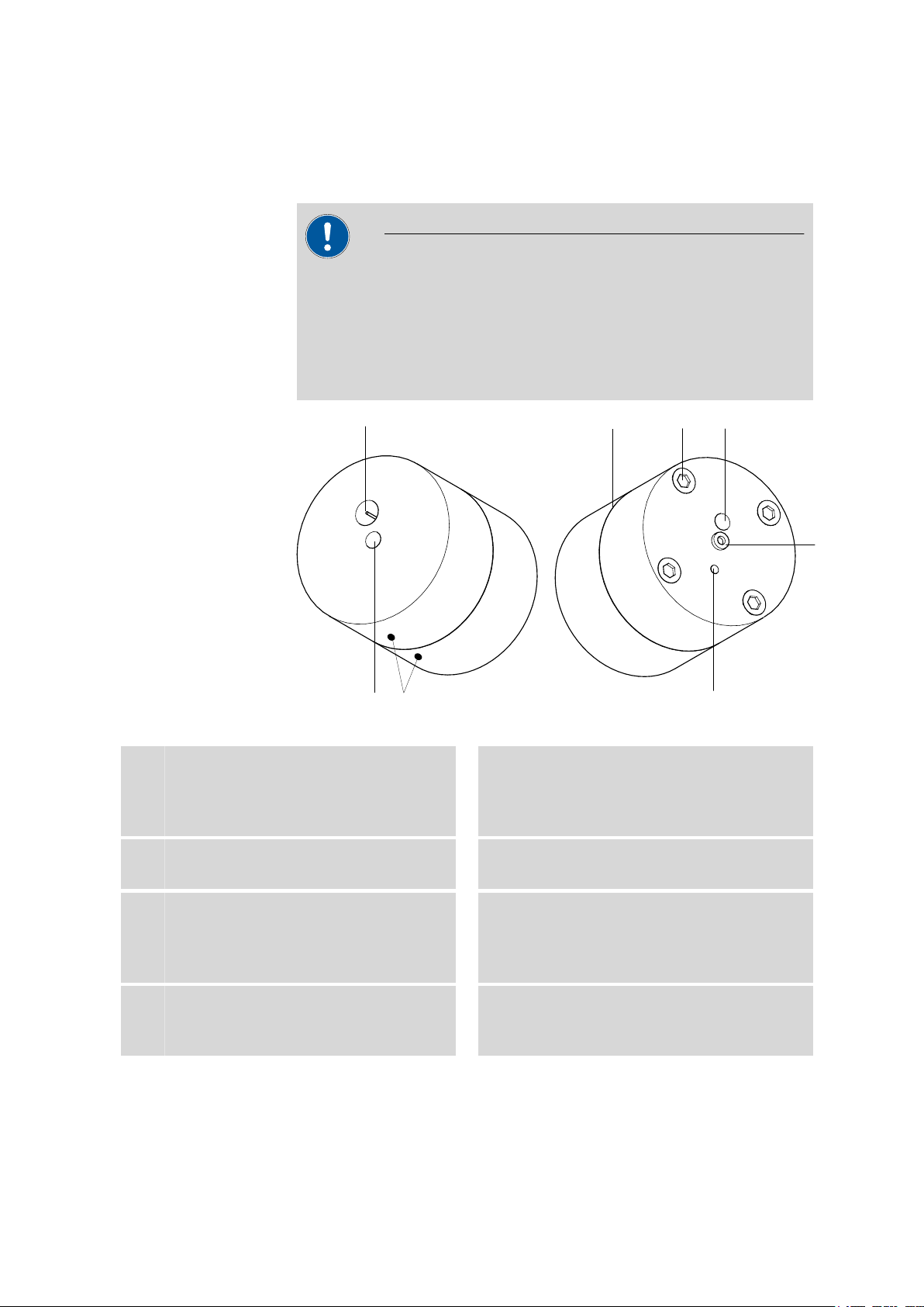
4 6.2744.130 Pressure screw for Bioscan measuring cell
For connecting 1/16 in. capillaries.
1 8.110.8003EN Manual IC Equipment Set – Flow Cell for
Bioscan 6.5331.0X0
■■■■■■■■■■■■■■■■■■■■■■
4.2 Equipment set with GC flow cell for Bioscan
6.5331.020 IC Equipment Set with Glassy carbon flow cell
Qty. Order no. Description
1 6.1254.050 Glassy carbon flow cell for Bioscan
Flow cell for Bioscan, electrode material: glassy carbon
Material: Glassy carbon
Material remark: Working electrode
1 6.1254.020 Distance piece for Bioscan flow cell, 50 µm
50 µm Spacer for Bioscan flow-through cell
Material: Plastic
Height (mm): 0.05
■■■■■■■■
10
IC Equipment Set Flow Cell for Bioscan
Page 17
■■■■■■■■■■■■■■■■■■■■■■
Qty. Order no. Description
1 6.2621.150 Hexagon key 3 mm for Bioscan
Hexagon key 3 mm for Bioscan
4 6.2744.130 Pressure screw for Bioscan measuring cell
For connecting 1/16 in. capillaries.
4 Accessories
1 8.110.8003EN Manual IC Equipment Set – Flow Cell for
Bioscan 6.5331.0X0
4.3 Equipment set with Pt flow cell of Bioscan
6.5331.030 IC Equipment Set with Platinum flow cell
Qty. Order no. Description
1 6.1254.060 Platinum flow cell for Bioscan
Flow cell for Bioscan, electrode material: Platinum
Material: Platinum
Material remark: Working electrode
IC Equipment Set Flow Cell for Bioscan
■■■■■■■■
11
Page 18

4.3 Equipment set with Pt flow cell of Bioscan
Qty. Order no. Description
1 6.1254.020 Distance piece for Bioscan flow cell, 50 µm
50 µm Spacer for Bioscan flow-through cell
Material: Plastic
Height (mm): 0.05
1 6.2621.150 Hexagon key 3 mm for Bioscan
Hexagon key 3 mm for Bioscan
■■■■■■■■■■■■■■■■■■■■■■
4 6.2744.130 Pressure screw for Bioscan measuring cell
For connecting 1/16 in. capillaries.
1 8.110.8003EN Manual IC Equipment Set – Flow Cell for
Bioscan 6.5331.0X0
■■■■■■■■
12
IC Equipment Set Flow Cell for Bioscan
Page 19
■■■■■■■■■■■■■■■■■■■■■■
4.4 Equipment set with Ag flow cell for Bioscan
6.5331.040 IC Equipment Set with Silver flow cell
Qty. Order no. Description
1 6.1254.070 Silver flow cell for Bioscan
Flow cell for Bioscan, electrode material: Silver
Material: Silver
Material remark: Working electrode
1 6.1254.020 Distance piece for Bioscan flow cell, 50 µm
50 µm Spacer for Bioscan flow-through cell
Material: Plastic
Height (mm): 0.05
4 Accessories
1 6.2621.150 Hexagon key 3 mm for Bioscan
Hexagon key 3 mm for Bioscan
IC Equipment Set Flow Cell for Bioscan
■■■■■■■■
13
Page 20

4.4 Equipment set with Ag flow cell for Bioscan
Qty. Order no. Description
4 6.2744.130 Pressure screw for Bioscan measuring cell
For connecting 1/16 in. capillaries.
1 8.110.8003EN Manual IC Equipment Set – Flow Cell for
Bioscan 6.5331.0X0
■■■■■■■■■■■■■■■■■■■■■■
■■■■■■■■
14
IC Equipment Set Flow Cell for Bioscan
Page 21

■■■■■■■■■■■■■■■■■■■■■■
Index
Index
A
Accessories ................................. 9
auxiliary electrode ...................... 3
C
Cell volume ................................ 6
D
Distance piece ............................ 3
Distand piece ............................. 6
G
Glassy Carbon flow cell
Technical data ...................... 7
Glassy Carbon Flow-through Cell
Accessory ........................... 10
Gold flow cell
Accessory ............................. 9
Technical data ...................... 6
I
Installation ................................. 3
P
Platinum flow cell
Technical data ...................... 7
Platinum Flow-through Cell
Accessory ........................... 11
R
reference electrode .................... 3
S
Silver flow cell
Technical data ...................... 8
Silver Flow-through Cell
Zubehör ............................. 13
T
Technical data ............................ 6
Temperature ............................... 6
W
working electrode ...................... 3
IC Equipment Set Flow Cell for Bioscan
■■■■■■■■
15
 Loading...