

Page 1
915 KF Ti-Touch
Manual
8.915.8005EN / 2014-03-10
Page 2

Page 3

Metrohm AG
CH-9100 Herisau
Switzerland
Phone +41 71 353 85 85
Fax +41 71 353 89 01
info@metrohm.com
www.metrohm.com
915 KF Ti-Touch
Program version 5.915.0030
8.915.8005EN / 2014-03-10
Manual
ebe
Page 4

Teachware
Metrohm AG
CH-9100 Herisau
teachware@metrohm.com
This documentation is protected by copyright. All rights reserved.
Although all the information given in this documentation has been
checked with great care, errors cannot be entirely excluded. Should you
notice any mistakes please send us your comments using the address
given above.
Documentation in additional languages can be found on
http://documents.metrohm.com.
Melody for the BEEP command: excerpt from "En Altfrentsche", with kind
permission of the Laseyer Quartett, Appenzell.
Page 5

■■■■■■■■■■■■■■■■■■■■■■
Table of contents
1 Introduction 1
1.1 Instrument description ......................................................... 1
1.1.1 Titration and measuring modes ................................................ 1
1.1.2 Connectors .............................................................................. 2
1.1.3 Intended use ........................................................................... 2
1.2 About the documentation ................................................... 3
1.2.1 Symbols and conventions ........................................................ 3
2 Safety instructions 5
2.1 General notes on safety ....................................................... 5
2.2 Electrical safety ..................................................................... 5
2.3 Tubing and capillary connections ....................................... 6
2.4 Flammable solvents and chemicals ..................................... 6
Table of contents
2.5 Recycling and disposal ......................................................... 7
3 Overview of the instrument 8
3.1 Front of the instrument ........................................................ 8
3.2 Rear of the instrument ......................................................... 9
4 Installation 10
4.1 Setting up the instrument .................................................. 10
4.1.1 Packaging .............................................................................. 10
4.1.2 Checks .................................................................................. 10
4.1.3 Location ................................................................................ 10
4.2 Connecting the power supply unit .................................... 10
4.3 Connecting MSB devices .................................................... 12
4.3.1 Connecting dosing devices .................................................... 13
4.3.2 Connecting an additional stirrer or titration stand .................. 14
4.3.3 Connecting a Remote Box ..................................................... 14
4.4 Connecting USB devices ..................................................... 15
4.4.1 General ................................................................................. 15
4.4.2 Connecting a USB hub ........................................................... 15
4.4.3 Connecting a printer .............................................................. 15
4.4.4 Connecting a balance ............................................................ 16
4.4.5 Connecting a PC keyboard ..................................................... 17
4.4.6 Connecting a barcode reader ................................................. 17
4.4.7 Connecting a Sample Processor ............................................. 18
915 KF Ti-Touch
4.5 Setting up the titration vessel ........................................... 19
■■■■■■■■
III
Page 6

Table of contents
■■■■■■■■■■■■■■■■■■■■■■
4.6 Connecting sensors ............................................................ 19
4.6.1 General ................................................................................. 19
4.6.2 Connecting a polarizable electrode ........................................ 19
4.6.3 Connecting a temperature sensor .......................................... 20
4.7 Connecting the Ti-Touch to a network ............................ 21
5 Titrations 23
5.1 Water determination according to Karl Fischer (KFT) ..... 23
6 Operation 24
6.1 Switching the instrument on and off ............................... 24
6.2 Fundamentals of operation ............................................... 26
6.2.1 Touch-sensitive screen ........................................................... 26
6.2.2 Display elements and controls ................................................ 26
6.2.3 Status display ........................................................................ 27
6.2.4 Entering text and numbers ..................................................... 28
7 System settings 31
7.1 General system settings ..................................................... 31
7.1.1 Selecting the dialog language ................................................ 31
7.1.2 Setting the date, time and local time ..................................... 32
7.2 System-specific dialog options .......................................... 33
7.3 User administration ............................................................ 37
7.3.1 Editing the user configuration ................................................ 38
7.3.2 Creating an identification profile ............................................ 40
7.3.3 Defining login options ........................................................... 41
7.3.4 Password options .................................................................. 42
7.4 Measured value display ..................................................... 45
7.5 Acoustic signals .................................................................. 45
8 Titrants 46
8.1 Adding a new titrant .......................................................... 47
8.2 Editing titrant data ............................................................. 48
8.3 Monitoring the working life .............................................. 50
8.4 Dosing unit .......................................................................... 51
8.4.1 Parameters for preparing (PREP) and emptying (EMPTY) ......... 52
8.4.2 Tubing parameters ................................................................. 53
8.4.3 Shift direction of the valve disk .............................................. 56
■■■■■■■■
IV
8.5 Exchange unit ..................................................................... 57
8.5.1 Parameters for the preparation (PREP) .................................... 58
8.5.2 Tubing parameters ................................................................. 59
8.6 GLP test for exchange unit and dosing unit .................... 61
915 KF Ti-Touch
Page 7

■■■■■■■■■■■■■■■■■■■■■■
9 Reagents 66
10 Sensors 70
11 Device manager 74
Table of contents
8.7 Titer determination options and data .............................. 63
8.7.1 Titer validity ........................................................................... 63
8.7.2 Properties of the previous titer determinations ....................... 64
9.1 Editing reagent data .......................................................... 66
9.2 Reagent monitoring ........................................................... 67
10.1 Adding a new sensor ......................................................... 71
10.2 Editing the sensor data ...................................................... 71
10.3 Monitoring the working life .............................................. 72
11.1 Adding a new device .......................................................... 75
11.2 Configuring the instrument ............................................... 75
11.3 Ti-Touch ............................................................................... 76
11.3.1 E-mail .................................................................................... 77
11.3.2 PC/LIMS report ...................................................................... 78
11.3.3 Shared memory ..................................................................... 79
11.3.4 TCP/IP settings ....................................................................... 81
11.4 Metrohm control devices ................................................... 82
11.4.1 Properties – Measuring input ................................................. 83
11.4.2 Properties – MSB connector ................................................... 84
11.4.3 Properties – Peripheral devices ............................................... 85
11.5 USB Sample Processor ....................................................... 85
11.5.1 Properties – Sample Processor ............................................... 86
11.5.2 Properties – Tower ................................................................ 87
11.5.3 Properties – Swing Head ........................................................ 89
11.6 Sample racks ....................................................................... 93
11.6.1 Editing rack data .................................................................... 95
11.6.2 Rack adjustment .................................................................. 100
11.7 Printer ................................................................................ 101
11.7.1 PDF settings ......................................................................... 103
11.7.2 Network printer ................................................................... 104
11.7.3 More options ....................................................................... 105
11.8 Balance .............................................................................. 106
11.9 USB/RS-232 adapter ......................................................... 107
11.10 PC keyboard ...................................................................... 109
11.11 Barcode reader ................................................................. 110
915 KF Ti-Touch
■■■■■■■■
V
Page 8

Table of contents
■■■■■■■■■■■■■■■■■■■■■■
12 File manager 113
12.1 Managing files .................................................................. 113
12.1.1 Copying a file ...................................................................... 115
12.1.2 Renaming a file ................................................................... 115
12.1.3 File properties ...................................................................... 116
12.2 External storage medium ................................................ 117
12.3 Creating backups / Restoring data ................................. 119
12.3.1 Restoring data ..................................................................... 119
13 GLP manager 121
13.1 Automatic system test ..................................................... 122
13.2 Test tools .......................................................................... 122
13.3 GLP tests for measurement and titration ...................... 123
13.3.1 Parameter description .......................................................... 124
13.4 System validation ............................................................. 127
13.4.1 Parameter description .......................................................... 128
13.5 System monitoring ........................................................... 131
13.5.1 Service interval .................................................................... 131
13.5.2 Backup interval .................................................................... 132
14 Common variables 133
14.1 Editing common variables ............................................... 134
14.2 Properties of common variables ..................................... 135
14.3 Monitoring validity ........................................................... 136
14.4 Assigning a result automatically to a common varia-
ble ...................................................................................... 137
15 Templates 139
15.1 Sample data ...................................................................... 139
15.1.1 Sample identification list ...................................................... 140
15.1.2 Sample assignment table ..................................................... 141
15.2 Custom result templates .................................................. 143
15.2.1 Editing result templates ....................................................... 144
15.3 Input lines ......................................................................... 147
15.3.1 Editing the input signal ........................................................ 148
■■■■■■■■
VI
15.4 Output lines ...................................................................... 149
15.4.1 Editing the output signal ...................................................... 151
15.5 Report header ................................................................... 152
16 Methods 154
16.1 Creating a new method ................................................... 154
915 KF Ti-Touch
Page 9

■■■■■■■■■■■■■■■■■■■■■■
17 Control 170
18 Favorites 174
19 Sample data 178
Table of contents
16.2 Saving a method ............................................................... 155
16.3 Loading a method ............................................................ 156
16.4 Editing a method .............................................................. 157
16.4.1 Inserting a command ........................................................... 158
16.5 Method options ................................................................ 159
16.5.1 Start options ........................................................................ 160
16.5.2 Stop options ........................................................................ 162
16.5.3 Sample data ........................................................................ 163
16.5.4 Method properties ............................................................... 167
16.5.5 Note .................................................................................... 167
16.5.6 Saving a determination automatically ................................... 167
18.1 Creating favorites ............................................................. 175
18.1.1 Editing favorites ................................................................... 175
19.1 Entering sample data in the main dialog ....................... 178
19.2 Requesting sample data at the start of the determina-
tion .................................................................................... 179
20 Sample table 181
20.1 General .............................................................................. 181
20.2 Edit the sample data ........................................................ 184
20.3 Properties .......................................................................... 186
21 Determination run 189
21.1 Carrying out a single determination ............................... 189
21.2 Performing a sample series ............................................. 190
21.3 Canceling determinations manually ............................... 191
22 Live modifications 192
22.1 Editing the sample data of the running determina-
tion .................................................................................... 192
22.2 Editing the sample table while a determination is run-
ning .................................................................................... 193
915 KF Ti-Touch
22.3 Live display ....................................................................... 194
22.4 Live parameters ................................................................ 196
■■■■■■■■
VII
Page 10

Table of contents
■■■■■■■■■■■■■■■■■■■■■■
23 Results and more determination data 198
23.1 More determination data ................................................ 199
23.1.1 Details ................................................................................. 200
23.2 Messages ........................................................................... 202
23.3 Local common variables .................................................. 202
23.4 Determination properties ................................................ 203
23.5 Loading a determination ................................................. 204
23.5.1 Determination list ................................................................ 205
23.6 Saving a determination .................................................... 210
23.7 Curves ................................................................................ 210
23.8 Recalculation and reevaluation ....................................... 212
24 Statistics 214
24.1 Displaying details for a result .......................................... 216
24.2 Deleting statistical data ................................................... 217
24.3 Adding a determination to a determination series ....... 217
25 Result table 219
25.1 Properties .......................................................................... 220
25.2 Saving the result table ..................................................... 224
25.3 Loading the result table ................................................... 224
26 Printing 225
26.1 General report options ..................................................... 227
26.2 Settings of the individual reports ................................... 228
26.3 List of all printable reports .............................................. 229
27 Manual control 233
27.1 Opening and closing the manual control ....................... 234
27.2 Measuring ......................................................................... 235
27.2.1 Parameter description .......................................................... 236
27.3 Dosing ............................................................................... 237
27.3.1 Continuous dosing .............................................................. 239
27.3.2 Dosing fixed volumes ........................................................... 241
27.3.3 Preparing ............................................................................. 244
27.3.4 Emptying ............................................................................. 245
27.3.5 Filling .................................................................................. 245
27.3.6 Replacing reagent ................................................................ 246
VIII
■■■■■■■■
27.4 Stirring ............................................................................... 246
915 KF Ti-Touch
Page 11

■■■■■■■■■■■■■■■■■■■■■■
28 Parameters 259
Table of contents
27.5 Remote .............................................................................. 248
27.6 USB Sample Processor ..................................................... 249
27.6.1 Moving the lift ..................................................................... 251
27.6.2 Moving to a rack position .................................................... 253
27.6.3 External positions ................................................................ 254
28.1 Volumetric Karl Fischer titrations (KFT) ......................... 259
28.1.1 Start conditions ................................................................... 259
28.1.2 Control parameters .............................................................. 261
28.1.3 Titration parameters ............................................................ 264
28.1.4 Stop conditions ................................................................... 265
28.1.5 Conditioning ....................................................................... 266
28.1.6 Cell ...................................................................................... 268
28.1.7 Control device ..................................................................... 268
28.1.8 Sensor ................................................................................. 269
28.1.9 Dosing device ...................................................................... 270
28.1.10 Stirrer .................................................................................. 271
28.2 Measurements (MEAS) ..................................................... 272
28.2.1 Measuring parameters ......................................................... 272
28.2.2 Control device ..................................................................... 274
28.2.3 Sensor ................................................................................. 274
28.2.4 Stirrer .................................................................................. 276
28.3 Evaluations (EVAL) ........................................................... 277
28.3.1 Fixed endpoint evaluation (EVAL FIX-EP) .............................. 277
28.3.2 Minimum and maximum evaluation (EVAL MIN/MAX) .......... 279
28.3.3 Break point evaluation (EVAL BREAK) ................................... 280
28.3.4 Rate evaluation (EVAL RATE) ................................................ 282
28.4 Calculations ....................................................................... 283
28.4.1 Calculations (CALC) ............................................................. 283
28.4.2 Calculations (CALC LIVE) ...................................................... 291
28.4.3 Formula editor ..................................................................... 293
28.5 Reports (REPORT) ............................................................. 299
28.5.1 General report options ......................................................... 299
28.5.2 Settings of the individual reports .......................................... 300
28.5.3 List of reports ...................................................................... 301
28.6 Dosing and Liquid Handling ............................................ 304
28.6.1 Preparing an exchange or dosing unit (PREP) ........................ 304
28.6.2 Emptying a dosing unit (EMPTY) .......................................... 305
28.6.3 Dosing a specified volume (ADD) ......................................... 306
28.6.4 Liquid Handling (LQH) .......................................................... 311
28.7 Communication ................................................................ 314
28.7.1 Scanning remote lines (SCAN) .............................................. 314
28.7.2 Setting remote lines (CTRL) .................................................. 316
28.7.3 Scanning the RS-232 interface (SCAN RS) ............................. 317
28.7.4 Defining RS-232 commands (CONTROL RS) .......................... 318
915 KF Ti-Touch
■■■■■■■■
IX
Page 12

Table of contents
■■■■■■■■■■■■■■■■■■■■■■
28.8 Automation ....................................................................... 319
28.8.1 Rotating sample rack (MOVE) .............................................. 319
28.8.2 Moving the lift (LIFT) ............................................................ 321
28.8.3 Controlling pumps (PUMP) ................................................... 322
28.8.4 Resetting the rack (RACK) .................................................... 323
28.8.5 Defining the sample variable (SAMPLE) ................................ 323
28.8.6 Creating a subsequence (SUBSEQ) ....................................... 324
28.9 Miscellaneous commands ................................................ 327
28.9.1 Controlling a stirrer (STIR) .................................................... 327
28.9.2 Pausing the method run (WAIT) ........................................... 328
28.9.3 Scan data (REQUEST) ........................................................... 329
28.9.4 Defining an acoustic signal (BEEP) ........................................ 330
28.9.5 Canceling the method run (END) ......................................... 330
29 Operation and maintenance 331
29.1 System initialization ......................................................... 331
29.2 Quality management and qualification with Metrohm 332
30 Troubleshooting 333
30.1 Editing methods ............................................................... 333
30.2 Sample table ..................................................................... 333
30.3 Results/Statistics ............................................................... 333
30.4 Printing .............................................................................. 334
30.5 Manual control ................................................................. 334
30.6 Titration stand with pump .............................................. 335
30.7 Karl Fischer titration ........................................................ 335
31 Appendix 338
31.1 Dosing unit ........................................................................ 338
31.1.1 Maximum dosing and filling rate .......................................... 338
31.1.2 Default parameters for preparing (PREP) and emptying
(EMPTY) ............................................................................... 338
31.2 Exchange unit ................................................................... 339
31.2.1 Maximum dosing and filling rate .......................................... 339
31.2.2 Default parameters for preparing (PREP) .............................. 339
31.3 Stirring rate ....................................................................... 339
31.4 Balance .............................................................................. 340
■■■■■■■■
X
31.5 Remote interface .............................................................. 341
31.5.1 Pin assignment of the remote interface ................................ 341
31.6 Result variables as parameter setting ............................ 344
31.7 Diagnosis ........................................................................... 345
31.7.1 LCD test .............................................................................. 346
915 KF Ti-Touch
Page 13

■■■■■■■■■■■■■■■■■■■■■■
32 Technical specifications 355
Table of contents
31.7.2 Formatting an external storage medium ............................... 347
31.7.3 Removing an external storage medium ................................ 347
31.7.4 Adjusting the touch screen .................................................. 347
31.7.5 Testing the touch screen ...................................................... 348
31.7.6 Software update (loading program versions and language
files) .................................................................................... 349
31.7.7 Service ................................................................................. 352
31.8 Arithmetic algorithms in the Ti-Touch ........................... 353
32.1 Touch screen ..................................................................... 355
32.2 Measuring inputs .............................................................. 356
32.2.1 Polarizer .............................................................................. 356
32.2.2 Temperature ........................................................................ 356
32.3 Internal stirrer ................................................................... 357
32.4 Pump ................................................................................. 357
32.5 Interfaces .......................................................................... 357
32.6 Power supply .................................................................... 358
32.7 Safety specifications ........................................................ 358
32.8 Electromagnetic compatibility (EMC) ............................. 358
32.9 Ambient temperature ...................................................... 359
32.10 Reference conditions ........................................................ 359
32.11 Dimensions ........................................................................ 359
33 Warranty (guarantee) 360
34 Accessories 362
Index 364
915 KF Ti-Touch
■■■■■■■■
XI
Page 14

Table of figures
Table of figures
Figure 1 Front 915 KF Ti-Touch ....................................................................... 8
Figure 2 Rear 915 KF Ti-Touch ........................................................................ 9
Figure 3 Connecting the power supply unit ................................................... 11
Figure 4 MSB connections ............................................................................ 12
Figure 5 MSB connector ............................................................................... 13
Figure 6 Connecting a polarizable electrode .................................................. 20
Figure 7 Connecting a temperature sensor .................................................... 21
Figure 8 Connecting the Ti-Touch to a network ............................................ 22
Figure 9 Reagent dosing for KFT ................................................................... 23
Figure 10 Dosing unit – port assignment ......................................................... 56
Figure 11 Exchange unit – tubing connections ................................................ 61
Figure 12 Live display "Preparing the dosing unit" ......................................... 244
Figure 13 Live display "Preparing the exchange unit" ..................................... 245
Figure 14 Evaluation of minimum and maximum ........................................... 279
Figure 15 Evaluation of a break point ............................................................ 280
Figure 16 Rotational speed depending on stirring rate .................................. 340
Figure 17 Connectors of the Remote Box ...................................................... 341
Figure 18 Pin assignment of remote socket and plug .................................... 341
■■■■■■■■■■■■■■■■■■■■■■
XII
■■■■■■■■
915 KF Ti-Touch
Page 15

■■■■■■■■■■■■■■■■■■■■■■
1 Introduction
1.1 Instrument description
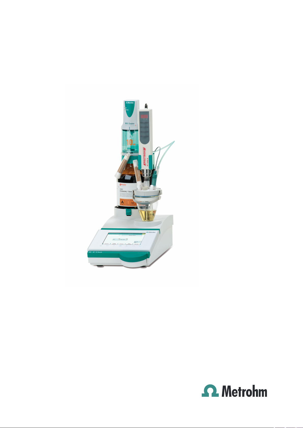
The 915 KF Ti-Touch is a compact titration system for volumetric Karl
Fischer titration. This newly designed titrator combines in a single device
the touch-sensitive color monitor for convenient and efficient operation,
the titration unit, the magnetic stirrer and the integrated membrane pump
for adding and aspirating solvents. The upper side of the housing offers
space for the titrant and the titration cell. The titrator is standard-equipped for operation with an external dosing drive of the 800 Dosino type
with a dosing unit. You can however also use a 805 Dosimat with an
exchange unit. Thanks to its compact construction, you can use the
915 KF Ti-Touch in a small space as a stand-alone titrator.
You manage titrants, sensors, methods, etc. conveniently in the internal
memory of the 915 KF Ti-Touch. You can also save your files externally
through the USB connector, e.g. on a USB flash drive. On this storage
medium you can not only store your methods and determinations, but
also create a backup together with all of the data and settings of your system.
1 Introduction
The integrated Ethernet connection is available to you should you wish to
connect your 915 KF Ti-Touch to a network. The network connection
offers you the following advantages:
■ Saving data to a PC within the network
■ Printing reports on a network printer
■ Sending displayed messages as e-mails
1.1.1 Titration and measuring modes
The 915 KF Ti-Touch supports the following titration and measuring
modes.
■ KFT
Volumetric water content determination according to Karl Fischer.
Measuring modes:
– Ipol (voltametric measurement with selectable polarization cur-
rent)
– Upol (amperometric measurement with selectable polarization
voltage)
915 KF Ti-Touch
■■■■■■■■
1
Page 16

1.1 Instrument description
■ MEAS
1.1.2 Connectors
The 915 KF Ti-Touch is equipped with the following connectors:
■ Mains connection
■ Two MSB connectors (Metrohm Serial Bus)
■ USB connector
■ Sensor connectors
■ Ethernet connector
■ Two connection nipples
■■■■■■■■■■■■■■■■■■■■■■
Measuring modes:
– Ipol (voltametric measurement with selectable polarization cur-
rent)
– Upol (amperometric measurement with selectable polarization
voltage)
– T (temperature measurement)
For connecting to the mains supply with the aid of the power supply
unit provided.
For connecting dosing devices, stirrers or a Remote Box.
For connecting peripheral devices (printer, PC keyboard, etc.), a USB
Sample Processor, a USB flash drive or a USB hub.
One connection each for:
– polarizable electrodes
– temperature sensors (Pt1000 or NTC)
For connecting the Ti-Touch to a network.
For connecting tubing for aspirating solvent and extracting the contents of the titration cell.
1.1.3 Intended use
■■■■■■■■
2
The 915 KF Ti-Touch is designed for usage as a titrator in analytical laboratories. Its main application field is volumetric Karl Fischer titration.
This instrument is suitable for processing chemicals and flammable samples. The usage of the 915 KF Ti-Touch therefore requires that the user
has basic knowledge and experience in the handling of toxic and caustic
substances. Knowledge with respect to the application of the fire prevention measures prescribed for laboratories is also mandatory.
915 KF Ti-Touch
Page 17
■■■■■■■■■■■■■■■■■■■■■■
1.2 About the documentation
CAUTION
Please read through this documentation carefully before putting the
instrument into operation. The documentation contains information
and warnings which the user must follow in order to ensure safe operation of the instrument.
1.2.1 Symbols and conventions
The following symbols and formatting may appear in this documentation:
Cross-reference to figure legend
The first number refers to the figure number, the second to the instrument part in the figure.
1 Introduction
Instruction step
Carry out these steps in the sequence shown.
Method Dialog text, parameter in the software
File ▶ New Menu or menu item
[Next] Button or key
WARNING
This symbol draws attention to a possible life-threatening hazard or risk of injury.
WARNING
This symbol draws attention to a possible hazard due
to electrical current.
WARNING
This symbol draws attention to a possible hazard due
to heat or hot instrument parts.
WARNING
This symbol draws attention to a possible biological
hazard.
915 KF Ti-Touch
CAUTION
This symbol draws attention to possible damage to
instruments or instrument parts.
■■■■■■■■
3
Page 18

1.2 About the documentation
■■■■■■■■■■■■■■■■■■■■■■
NOTE
This symbol highlights additional information and
tips.
■■■■■■■■
4
915 KF Ti-Touch
Page 19
■■■■■■■■■■■■■■■■■■■■■■
2 Safety instructions
2.1 General notes on safety
WARNING
This instrument may only be operated in accordance with the specifications in this documentation.
This instrument has left the factory in a flawless state in terms of technical
safety. To maintain this state and ensure non-hazardous operation of the
instrument, the following instructions must be observed carefully.
2.2 Electrical safety
2 Safety instructions
The electrical safety when working with the instrument is ensured as part
of the international standard IEC 61010.
WARNING
Only personnel qualified by Metrohm are authorized to carry out service
work on electronic components.
WARNING
Never open the housing of the instrument. The instrument could be
damaged by this. There is also a risk of serious injury if live components
are touched.
There are no parts inside the housing which can be serviced or replaced
by the user.
Mains voltage
WARNING
915 KF Ti-Touch
An incorrect mains voltage can damage the instrument.
Only operate this instrument with a mains voltage specified for it (see
rear panel of the instrument).
■■■■■■■■
5
Page 20
2.3 Tubing and capillary connections
Protection against electrostatic charges
WARNING
Electronic components are sensitive to electrostatic charges and can be
destroyed by discharges.
Do not fail to pull the mains cable out of the mains connection socket
before you set up or disconnect electrical plug connections at the rear
of the instrument.
2.3 Tubing and capillary connections
CAUTION
Leaks in tubing and capillary connections are a safety risk. Tighten all
connections well by hand. Avoid applying excessive force to tubing
connections. Damaged tubing ends lead to leakage. Appropriate tools
can be used to loosen connections.
■■■■■■■■■■■■■■■■■■■■■■
Check the connections regularly for leakage. If the instrument is used
mainly in unattended operation, then weekly inspections are mandatory.
2.4 Flammable solvents and chemicals
WARNING
All relevant safety measures are to be observed when working with
flammable solvents and chemicals.
■ Set up the instrument in a well-ventilated location (e.g. fume cup-
board).
■ Keep all sources of flame far from the workplace.
■ Clean up spilled liquids and solids immediately.
■ Follow the safety instructions of the chemical manufacturer.
■■■■■■■■
6
915 KF Ti-Touch
Page 21

■■■■■■■■■■■■■■■■■■■■■■
2.5 Recycling and disposal
This product is covered by European Directive 2002/96/EC, WEEE – Waste
from Electrical and Electronic Equipment.
The correct disposal of your old equipment will help to prevent negative
effects on the environment and public health.
More details about the disposal of your old equipment can be obtained
from your local authorities, from waste disposal companies or from your
local dealer.
2 Safety instructions
915 KF Ti-Touch
■■■■■■■■
7
Page 22
3.1 Front of the instrument
12
13
11
2
3
4
5
1
6
7
8 9 10
3 Overview of the instrument
3.1 Front of the instrument
■■■■■■■■■■■■■■■■■■■■■■
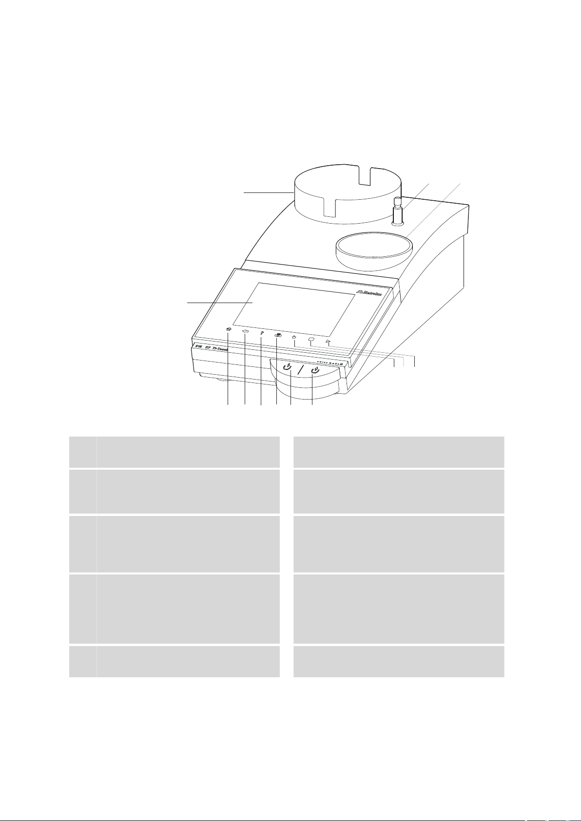
Figure 1 Front 915 KF Ti-Touch
Display
1
Touch-sensitive screen.
Fixed key [Back]
3
Saves the entry and opens the next-higher
dialog page.
Fixed key [Print]
5
Opens the print dialog.
Key
7
Pressing the key aspirates air out of the aspiration bottle. The vacuum in the aspiration
bottle suctions the liquid out of the KF titration cell and into the aspiration bottle.
Fixed key [STOP]
9
Cancels the running determination.
Fixed key [Home]
2
Opens the main dialog.
Fixed key [Help]
4
Opens the online help for the dialog displayed.
Key
6
Pressing the key pumps air into the solvent
bottle. The overpressure in the solvent bottle
pushes solvent into the KF titration cell.
Fixed key [Manual]
8
Opens the manual control.
Fixed key [START]
10
Starts a determination.
915 KF Ti-Touch
■■■■■■■■
8
Page 23
■■■■■■■■■■■■■■■■■■■■■■
8
9
3
5
6
10
3 Overview of the instrument
Bottle holder
11
With holding clips, for reagent bottle.
Titration stand
13
With built-in magnetic stirrer and membrane
pump for placement of the titration cell.
3.2 Rear of the instrument
Support rod (lower part)
12
For mounting the support rod (upper part).
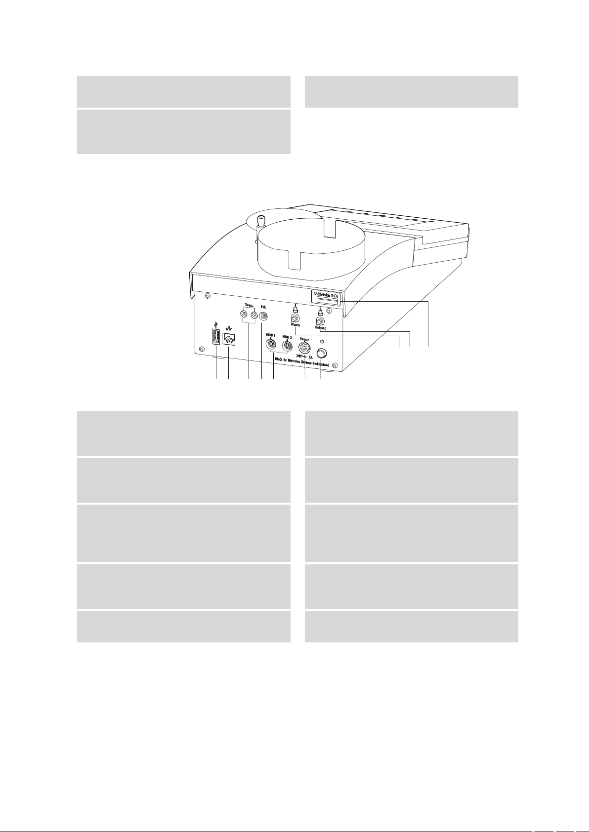
Figure 2 Rear 915 KF Ti-Touch
USB connector (type A)
1
For connecting a printer, USB flash drive,
USB hub, USB Sample Processor etc.
Temperature sensor connector (Temp.)
3
For connecting temperature sensors (Pt1000
or NTC). Two B sockets, 2 mm.
MSB connector (MSB 1 and MSB 2)
5
Metrohm Serial Bus. For connecting external
dosing devices, stirrers or a Remote Box.
Mini DIN, 8-pin.
Mains switch
7
Switch the instrument on/off.
Connection nipple for PVC tubing
9
For aspirating solvent.
Ethernet connector (RJ-45)
2
For connecting to a network.
Electrode connector (Pol.)
4
For connecting polarizable electrodes, e.g.
double Pt electrodes. Socket F.
Mains connection socket (Power)
6
For connecting the external power supply
unit.
Connection nipple for PVC tubing
8
For aspiration of the contents of the titration
cell.
Type plate
10
Contains the serial number.
915 KF Ti-Touch
■■■■■■■■
9
Page 24
4.1 Setting up the instrument
4 Installation
4.1 Setting up the instrument
4.1.1 Packaging
The instrument is supplied in highly protective special packaging together
with the separately packed accessories. Keep this packaging, as only this
ensures safe transportation of the instrument.
4.1.2 Checks
Immediately after receipt, check whether the shipment has arrived complete and without damage by comparing it with the delivery note.
4.1.3 Location
The instrument has been developed for operation indoors and may not be
used in explosive environments.
■■■■■■■■■■■■■■■■■■■■■■
Place the instrument in a location of the laboratory which is suitable for
operation, free of vibrations, protected from corrosive atmosphere, and
contamination by chemicals.
The instrument should be protected against excessive temperature fluctuations and direct sunlight.
4.2 Connecting the power supply unit
The 915 KF Ti-Touch has an external power supply unit for a 24 V power
supply (DC). This is connected to the mains connection of the Ti-Touch.
WARNING
An incorrect mains voltage can damage the device.
Operate the device only with the mains voltage specified for it. Use the
supplied power supply unit exclusively.
■■■■■■■■
10
915 KF Ti-Touch
Page 25
■■■■■■■■■■■■■■■■■■■■■■
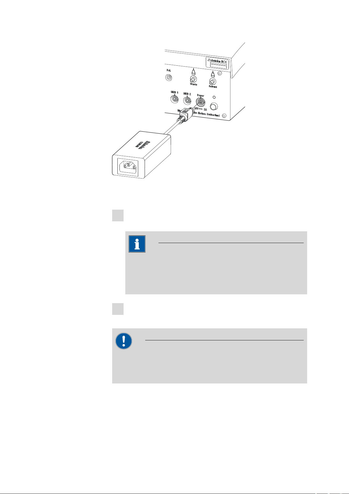
Figure 3 Connecting the power supply unit
Proceed as follows:
Connect the plug of the external power supply unit with the mains
1
connection of the Ti-Touch (see Figure 3, page 11).
4 Installation
NOTE
The plug of the power supply unit is protected against accidental
disconnection of the cable by means of a pull-out protection feature. If you wish to pull out the plug, you will first need to pull
back the outer plug sleeve marked with arrows.
Connect the mains cable with the external power supply unit of the
2
Ti-Touch and with the mains supply.
CAUTION
Switch off the Ti-Touch correctly by pressing the mains switch before
you disconnect the electricity supply. If this is not done, then there is a
danger of data loss.
915 KF Ti-Touch
■■■■■■■■
11
Page 26
4.3 Connecting MSB devices
MSB
Stirrer / Ti Stand
Dosimat / Dosino
Dosimat
Remote Box
Dosino
Ti Stand / Stirrer
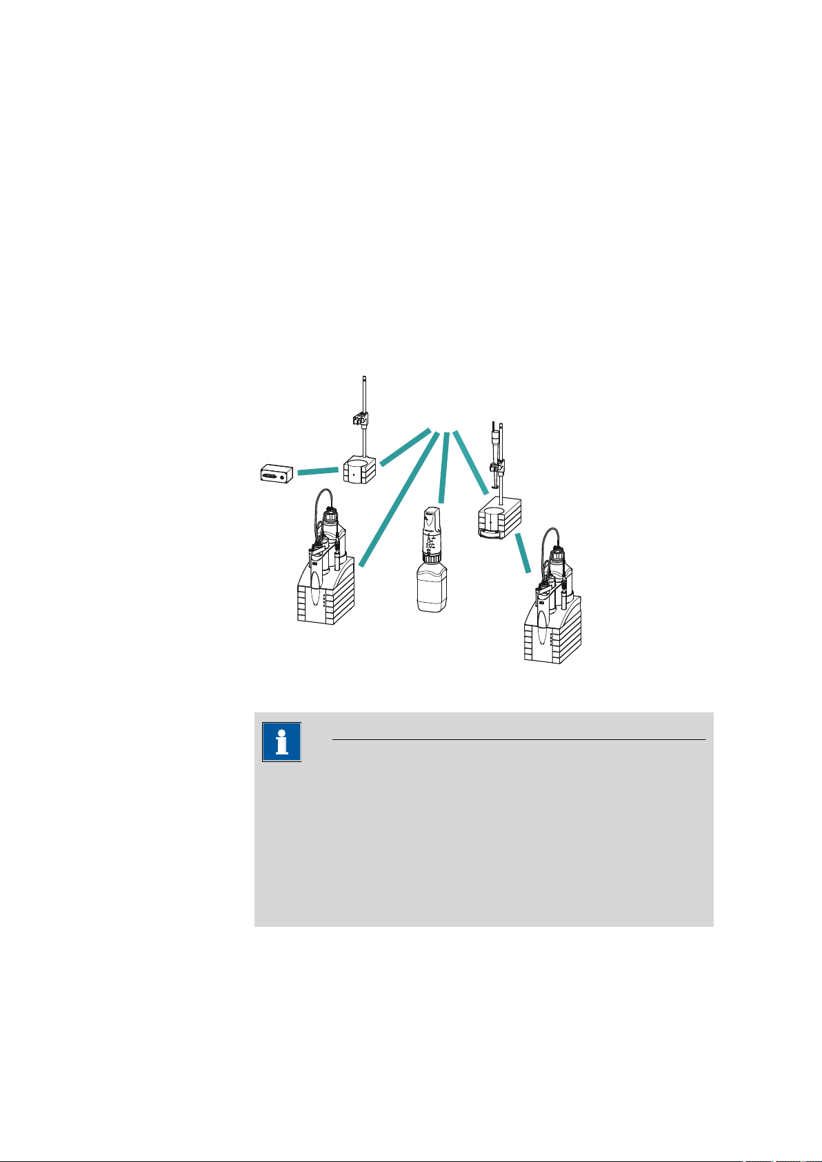
4.3 Connecting MSB devices
In order to connect MSB devices, e.g. dosing device or Remote-Box, the
Ti-Touch has two connectors at what is referred to as the Metrohm Serial
Bus (MSB). Various peripheral devices can be connected in sequence
(Daisy Chain) at a single MSB connector (8-pin Mini DIN socket) and be
controlled simultaneously by the Ti-Touch. In addition to the connection
cable, stirrers and the Remote Box are each equipped with their own MSB
socket for this purpose.
The following figure provides an overview of the devices that can be connected to an MSB socket, along with a number of different cabling variations.
■■■■■■■■■■■■■■■■■■■■■■
■■■■■■■■
12
Figure 4
MSB connections
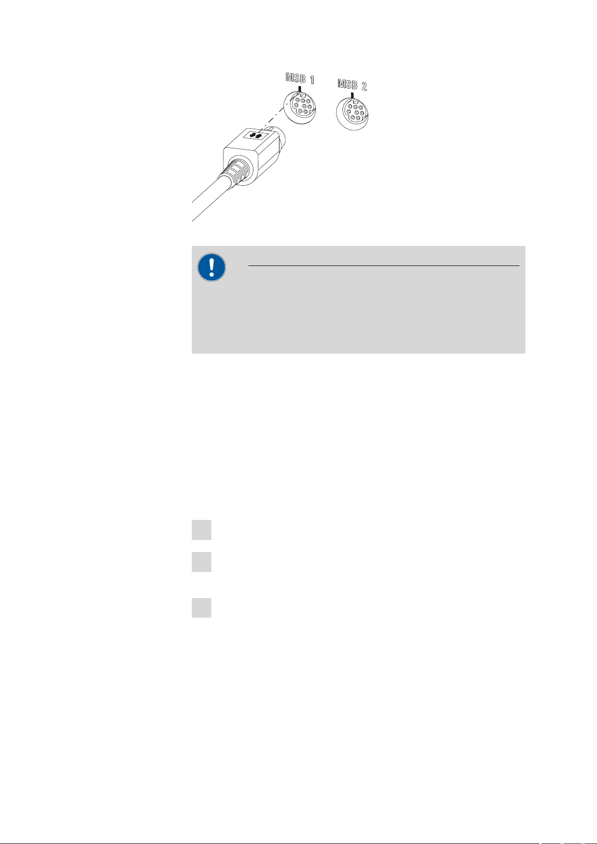
NOTE
When connecting MSB devices together, the following must be
observed:
■ Only one device of the same type can be used at a single MSB con-
nector at one time.
■ When making the connection, take care to ensure that the flat part
of the MSB plug marked with arrows is pointing in the direction of
the marking on the MSB connector (see Figure 5, page 13).
915 KF Ti-Touch
Page 27
■■■■■■■■■■■■■■■■■■■■■■
4 Installation
Figure 5 MSB connector
CAUTION
Switch off the Ti-Touch before you plug in MSB devices. When it is
switched on, the Ti-Touch automatically recognizes which device is connected to which MSB connector. The connected MSB devices are
entered automatically in the device manager.
MSB connections can be extended with the 6.2151.010 cable. The maximum connection length permitted is 6 m.
4.3.1 Connecting dosing devices
You can connect two dosing devices to the Ti-Touch.
The types of dosing devices that are supported are:
■ 800 Dosino
■ 805 Dosimat
Proceed as follows:
Switch off the Ti-Touch.
1
Connect the dosing device connection cable to an MSB connector
2
(2-5) on the rear side of the Ti-Touch.
Switch on the Ti-Touch.
3
915 KF Ti-Touch
■■■■■■■■
13
Page 28

4.3 Connecting MSB devices
■■■■■■■■■■■■■■■■■■■■■■
4.3.2 Connecting an additional stirrer or titration stand
In addition to the built-in magnetic stirrer, you can also use the magnetic
stirrers 801 Stirrer, 803 Ti Stand or the 804 Ti Stand with the propeller stirrer 802 Stirrer.
Proceed as follows:
Switch off the Ti-Touch.
1
Connect the connection cable of the magnetic stirrer or of the titra-
2
tion stand to MSB 2 (2-5) on the rear of the Ti-Touch.
Connect the propeller stirrer, if desired, to the stirrer connector of
3
the titration stand.
Switch on the Ti-Touch.
4
4.3.3 Connecting a Remote Box
Instruments that are controlled via remote lines and/or which send control
signals via remote lines can be connected using the 6.2148.010 Remote
Box. In addition to Metrohm, other instrument manufacturers also use
similar connectors that make it possible to connect different instruments
together. These interfaces are also frequently given the designations "TTL
Logic", "I/O Control" or "Relay Control" and generally have a signal level
of 5 volts.
Control signals are understood to be electrical line statuses or brief
(> 200 ms) electrical pulses which display the operational state of an
instrument or which trigger or report an event. Sequences on a variety of
instruments can thus be coordinated in a single complex automation system. No exchange of data is possible, however.
Proceed as follows:
Switch off the Ti-Touch.
1
Connect the Remote Box connection cable to an MSB connector
2
(2-5) on the rear side of the Ti-Touch.
Switch on the Ti-Touch.
3
■■■■■■■■
14
You can connect an 885 Compact Oven SC. The Remote Box also has an
MSB socket at which a further MSB device, e.g. a dosing device, can be
connected.
915 KF Ti-Touch
Page 29
■■■■■■■■■■■■■■■■■■■■■■
You will find precise information concerning the pin assignment of the
interface on the Remote Box in Appendix (see Chapter 31.5, page 341).
4.4 Connecting USB devices
4.4.1 General
The 915 KF Ti-Touch has a USB connector (Type A socket) for peripheral
devices with USB interface and for USB Sample Processors. If you wish to
connect more than one device to the USB, you can also use an additional
commercially available USB hub.
NOTE
We recommend that the Ti-Touch be switched off while you set up or
disconnect connections between the devices.
4.4.2 Connecting a USB hub
Use a USB hub with its own power supply.
4 Installation
Connect the USB hub as follows:
With the help of the 6.2151.030 cable (length 0.6 m) or the
1
6.2151.020 cable (length 1.8 m), connect the USB connector of the
Ti-Touch (Type A) with the USB connector of the hub (Type B, see
manual for the USB hub).
The USB hub is recognized automatically.
4.4.3 Connecting a printer
Printers that are connected to the 915 KF Ti-Touch must meet the following requirements:
■ Printer languages: HP-PCL, HP-PCL-GUI, Canon BJL Commands or
Epson ESC P/2
■ Paper format: A4 or Letter, single-sheet feed.
Connect the printer as follows:
With the aid of the 6.2151.020 cable, connect the USB connector of
1
the Ti-Touch (type A) with the USB connector of the printer (type B,
see manual for the printer).
Configure the printer in the device manager of the Ti-Touch (see
2
Chapter 11.7, page 101).
915 KF Ti-Touch
■■■■■■■■
15
Page 30
4.4 Connecting USB devices
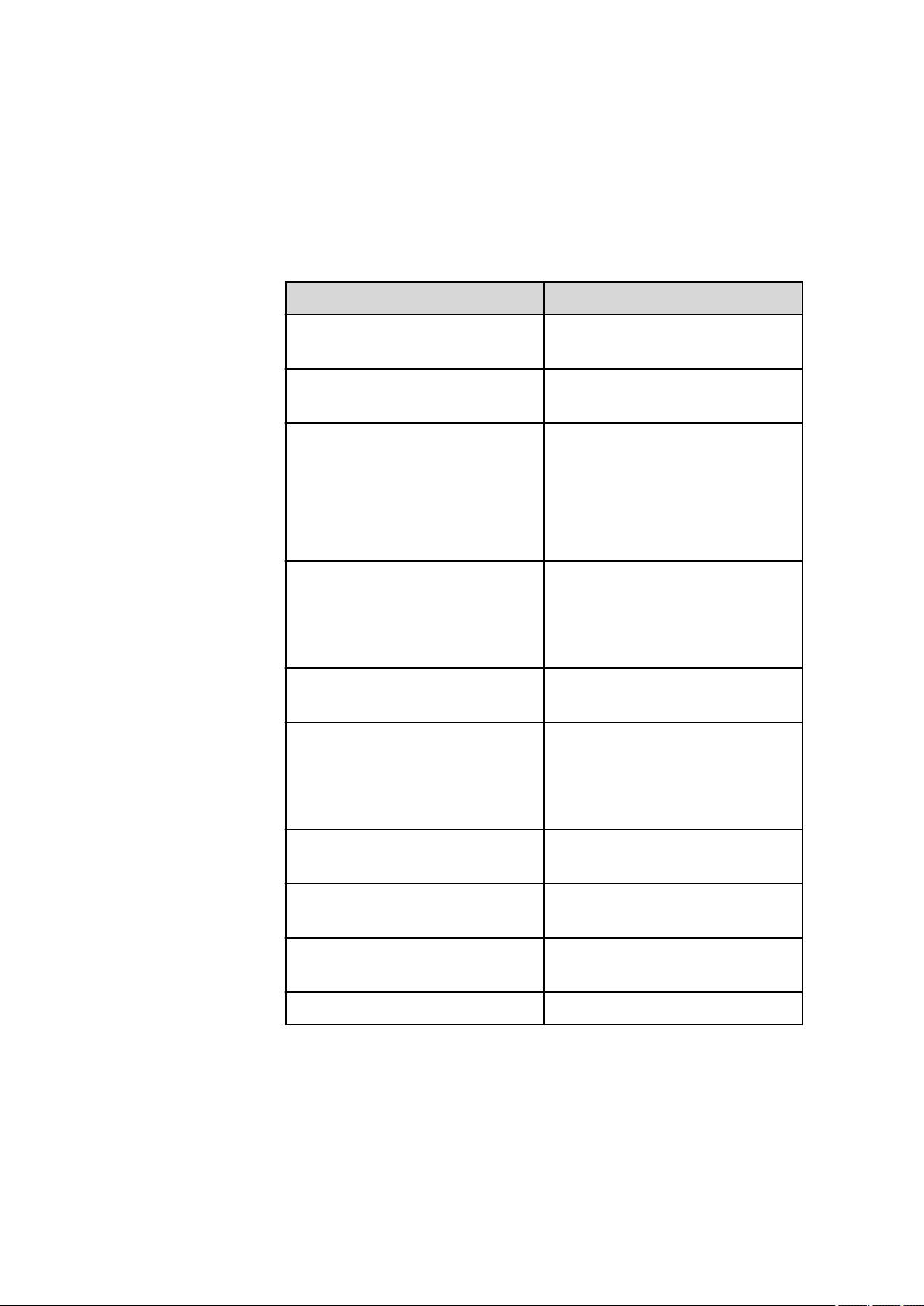
4.4.4 Connecting a balance
If you wish to connect a balance to the Ti-Touch, you will require a USB/
RS-232 adapter (6.2148.050).
The following table offers an overview of the balances that you can use
together with the Ti-Touch and of which cable you will need for connection to the RS-232 interface:
Balance Cable
■■■■■■■■■■■■■■■■■■■■■■
AND ER, FR, FX with RS-232 inter-
6.2125.020 + 6.2125.010
face (OP-03)
Mettler AB, AG, PR (LC-RS9) In the scope of delivery for the
balance
Mettler AM, PM, PE with interface
option 016
or
Mettler AJ, PJ with interface
option 018
6.2146.020 + 6.2125.010
also from Mettler: ME 47473
adapter and either ME 42500
hand switch or ME 46278 foot
switch
Mettler AT 6.2146.020 + 6.2125.010
also from Mettler: ME 42500
hand switch or ME 46278 foot
switch
Mettler AX, MX, UMX, PG, AB-S,
6.2134.120
PB-S, XP, XS
Mettler AE with interface option
011 or 012
6.2125.020 + 6.2125.010
also from Mettler: ME 42500
hand switch or ME 46278 foot
switch
■■■■■■■■
16
Ohaus Voyager, Explorer, Analyti-
Cable AS017-09 from Ohaus
cal Plus
Precisa balances with RS-232-C
6.2125.080 + 6.2125.010
interface
Sartorius MP8, MC, LA, Genius,
6.2134.060
Cubis
Shimadzu BX, BW 6.2125.080 + 6.2125.010
915 KF Ti-Touch
Page 31

■■■■■■■■■■■■■■■■■■■■■■
Connect the balance as follows:
Connect the USB plug of the USB/RS-232 adapter with the USB con-
1
nector of the Ti-Touch (Type A).
The USB/RS-232 adapter will be recognized automatically and
entered in the device manager of the Ti-Touch.
Connect the RS-232 interface of the USB/RS-232 adapter with the
2
RS-232 interface of the balance (see table for cable).
Switch on the balance.
3
If necessary, switch on the RS-232 interface of the balance.
4
Configure the RS-232 interface of the USB/RS-232 adapter in the
5
device manager of the Ti-Touch (see Chapter 11.9, page 107).
Enter and configure the balance in the device manager of the
6
Ti-Touch (see Chapter 11.8, page 106).
Make sure that the parameters of the USB/RS-232 adapter config-
7
ured in the device manager match those of the balance.
4 Installation
4.4.5 Connecting a PC keyboard
The PC keyboard is used as an aid for text and numerical input.
Connect the PC keyboard as follows:
Connect the USB plug of the keyboard with the USB connector of
1
the Ti-Touch (Type A).
Enter and configure the keyboard in the device manager of the
2
Ti-Touch (see Chapter 11.10, page 109).
4.4.6 Connecting a barcode reader
The barcode reader is used as an aid for text and numerical input. You can
connect a barcode reader with USB interface.
Connect the barcode reader as follows:
Connect the USB plug of the barcode reader with the USB connector
1
of the Ti-Touch (Type A).
915 KF Ti-Touch
■■■■■■■■
17
Page 32

4.4 Connecting USB devices
■■■■■■■■■■■■■■■■■■■■■■
Enter and configure the barcode reader in the device manager of the
2
(see Chapter 11.11, page 110).
Settings on the barcode reader:
Program the barcode reader as follows (also see manual for the barcode
reader):
Switch the barcode reader to programming mode.
1
Specify the desired layout for the keyboard (USA, Germany, France,
2
Spain, German-speaking Switzerland).
This setting must match the setting in the device manager.
Make sure that the barcode reader is set in such a way that Ctrl char-
3
acters (ASCII 00 to 31) can be sent.
Program the barcode reader in such a way that the ASCII character
4
02 (STX or Ctrl B) is sent as the first character. This first character is
normally referred to as the "Preamble" or "Prefix Code".
Program the barcode reader in such a way that the ASCII character
5
04 (EOT or Ctrl D) is sent as the last character. This last character is
normally referred to as the "Postamble", "Record Suffix" or "Postfix
Code".
Exit the programming mode.
6
4.4.7 Connecting a Sample Processor
If you wish to integrate your Ti-Touch in an automation system, then you
can connect the following Sample Processors to the USB connector:
■ 814 USB Sample Processor
■ 815 Robotic USB Sample Processor XL
The 6.2151.000 controller cable is required for connecting a USB Sample
Processor.
Connect the USB Sample Processor as follows:
Connect the USB Sample Processor to the mains supply.
1
Connect the USB Sample Processor to the Ti-Touch with the control-
2
ler cable.
■■■■■■■■
18
915 KF Ti-Touch
Page 33

■■■■■■■■■■■■■■■■■■■■■■
The USB Sample Processor will be recognized automatically and
entered in the device manager of the Ti-Touch.
NOTE
The plug on the controller cable is protected against accidental
disconnection by means of a pull-out protection feature. If you
wish to pull out the plug, you will first need to pull back the outer
plug sleeve marked with arrows.
Configure the USB Sample Processor in the device manager (see
3
Chapter 11.11, page 110).
4.5 Setting up the titration vessel
The tutorial for the 915 KF Ti-Touch includes a detailed description of how
to set up the Karl Fischer titration cell and what needs to be taken into
account while doing so.
4 Installation
4.6 Connecting sensors
4.6.1 General
The measuring interface includes one measuring input (Pol.) for a polarizable electrode and one measuring input (Temp.) for a temperature sensor
(Pt1000 or NTC).
4.6.2 Connecting a polarizable electrode
Connect the polarizable electrode as follows:
Plug the electrode plug into the Pol. socket of the Ti-Touch.
1
915 KF Ti-Touch
■■■■■■■■
19
Page 34

4.6 Connecting sensors
■■■■■■■■■■■■■■■■■■■■■■
Figure 6 Connecting a polarizable electrode
NOTE
The electrode cable is protected against accidental disconnection
of the cable by means of a pull-out protection. If you wish to
remove the plug, you will first need to pull back the outer plug
sleeve.
4.6.3 Connecting a temperature sensor
A temperature sensor of the Pt1000 or NTC type can be connected to the
Temp. connector.
Connect the temperature sensor as follows:
Plug the temperature sensor plugs into the Temp. sockets of the
1
Ti-Touch.
■■■■■■■■
20
915 KF Ti-Touch
Page 35

■■■■■■■■■■■■■■■■■■■■■■
4 Installation
Figure 7 Connecting a temperature sensor
NOTE
The red plug must always be plugged into the red socket for the
purpose of shielding against disruptions.
4.7 Connecting the Ti-Touch to a network
The 915 KF Ti-Touch has a network connection (Ethernet). This can be
used to integrate your Ti-Touch in your network. You can, for example,
store data on a PC within the network or print reports on a network
printer. In Chapter 11, page 74, you will find information as to which
settings are necessary for the network connection.
915 KF Ti-Touch
■■■■■■■■
21
Page 36

4.7 Connecting the Ti-Touch to a network
Figure 8 Connecting the Ti-Touch to a network
■■■■■■■■■■■■■■■■■■■■■■
■■■■■■■■
22
915 KF Ti-Touch
Page 37

■■■■■■■■■■■■■■■■■■■■■■
EP
KFT Ipol
KFT Upol
EP
V/mL
Continuous
dosing
Initial
dosing
V/mL
V/mL
U/mV
t/s
I/µA
Control range
Control range
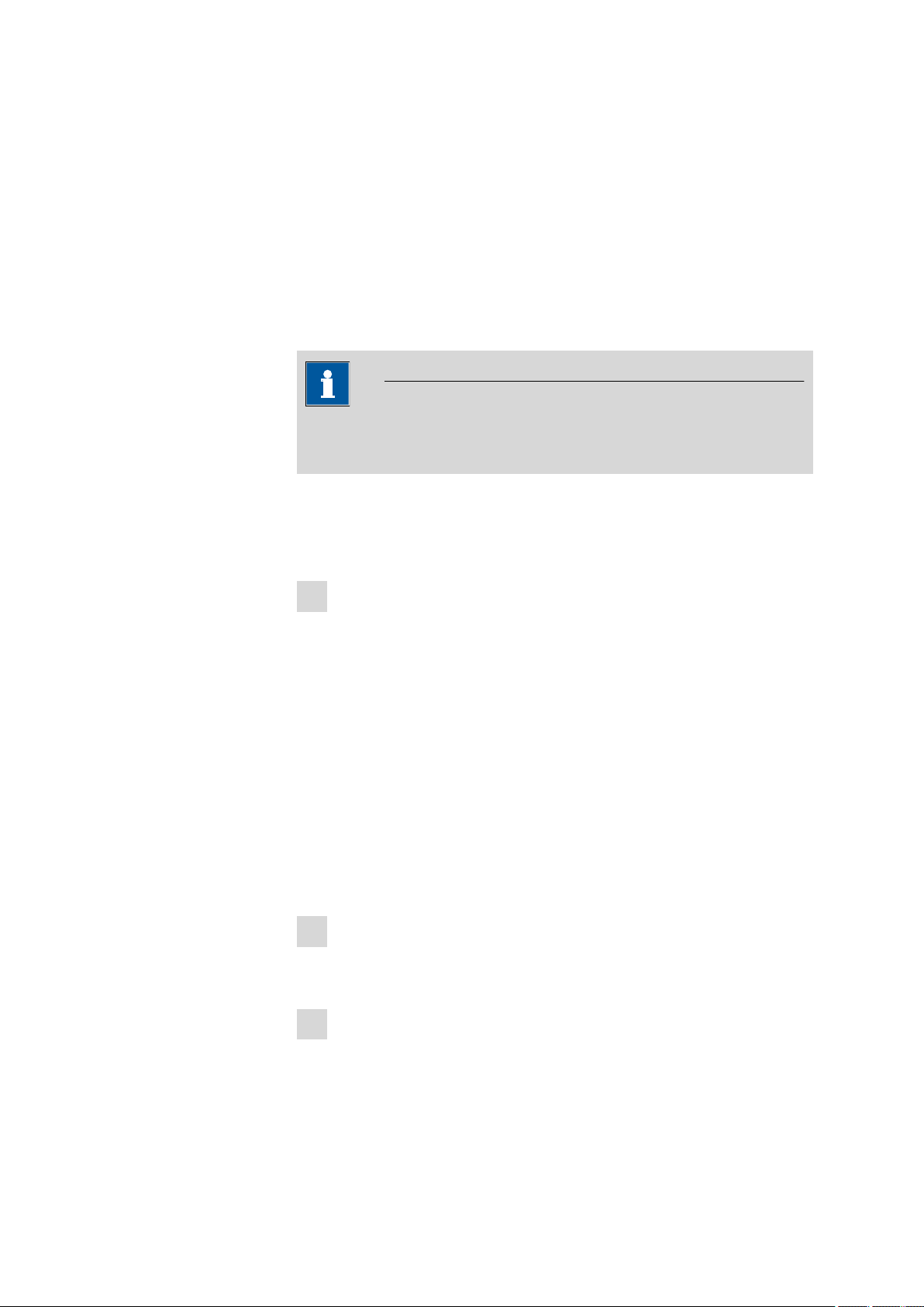
5 Titrations
5 Titrations
5.1 Water determination according to Karl Fischer (KFT)
Karl Fischer Titration is a method for volumetric water determination. Conditioning is carried out automatically both before and after the actual titration. The reagent dosing is controlled in such a way that a predefined
endpoint is reached as quickly and as accurately as possible. The volume
steps and the rate of reagent dosing are regulated by the difference
between the current measured value and the predefined endpoint. This
means that titration is performed more slowly in the control range and
that smaller volumes are added. The titration is stopped at the endpoint
either drift-controlled or after a waiting time. The volume dosed until the
endpoint is used to calculate the water content of the sample.
915 KF Ti-Touch
Figure 9
Reagent dosing for KFT
■■■■■■■■
23
Page 38

6.1 Switching the instrument on and off
6 Operation
6.1 Switching the instrument on and off
Switching on the instrument
CAUTION
Peripheral devices (e.g. printers) must be switched on before you switch
on the 915 KF Ti-Touch.
Proceed as follows:
■ Press the mains switch on the left-hand side of the rear panel of
1
the 915 KF Ti-Touch.
The 915 KF Ti-Touch is initialized. A system test is performed. This
process takes some time.
■ If a buret unit is attached, then a request appears to carry out the
Prepare function:
■■■■■■■■■■■■■■■■■■■■■■
■■■■■■■■
24
All tubings and the cylinder are rinsed with the
Prepare function.
The preparing of the buret unit is described in chapter 27.3.3,
page 244.
■ Confirm the message with [OK].
The main dialog is displayed:
915 KF Ti-Touch
Page 39

■■■■■■■■■■■■■■■■■■■■■■
6 Operation
Switching off the instrument
CAUTION
The 915 KF Ti-Touch must be switched off by pressing the mains switch
on the rear of the instrument before the electricity supply is interrupted.
If this is not done, then there is a danger of data loss.
Proceed as follows:
■ Press the mains switch on the left-hand side of the rear panel of
1
the 915 KF Ti-Touch.
The current data is saved and the system is shut down. This process
takes just a short time. At the same time, all other devices connected
to the 915 KF Ti-Touch via a USB cable are also being switched off.
915 KF Ti-Touch
■■■■■■■■
25
Page 40

6.2 Fundamentals of operation
6.2 Fundamentals of operation
6.2.1 Touch-sensitive screen
The entire Ti-Touch user interface is touch-sensitive. Simply touch a few of
the buttons on the interface to learn how a touch-sensitive screen reacts.
You can always return to the main dialog by touching [ ].
In order to activate an element on the Ti-Touch user interface, just touch
the screen with your fingertip, finger nail, the eraser of a pencil or a stylus
(special tool for operating instruments with touch-sensitive screens).
CAUTION
Never touch the touch screen with a pointed or sharp object such as a
ballpoint pen.
In the default setting, the software is configured in such a way that an
acoustic signal will be generated every time an active control is touched.
This setting can be deactivated in the system settings (see Chapter 7.5,
page 45).
■■■■■■■■■■■■■■■■■■■■■■
6.2.2 Display elements and controls
The following display elements and controls are available:
Table 1
Fixed keys which are always available
[Home] always opens the main dialog.
■■■■■■■■
26
915 KF Ti-Touch
Page 41

■■■■■■■■■■■■■■■■■■■■■■
6 Operation
[Back] saves the entry and opens the next-higher dialog
page.
[Help] opens the online help feature for the dialog displayed.
[Print] opens the printing dialog.
[Manual] opens the manual control.
[Stop] cancels the ongoing determination.
[Start] starts a determination.
The method loaded, the time and the system status are displayed in the
main dialog in the Title bar.
In the other dialogs, the title bar shows the headings of the next upper
level and of the displayed dialog. This is an aid for orientation during navigation through the user dialog.
Table 2
6.2.3 Status display
The current status of the system is displayed in the upper right-hand corner of the title bar:
Screen elements
Buttons open a new dialog when they are tapped.
Inactive buttons with gray lettering indicate
that the respective function is not available at the
moment.
Input fields open an input dialog when tapped
with the finger.
Tapping on the selection symbol opens a selection list.
A check box can also be activated or deactivated by tapping on it.
915 KF Ti-Touch
The instrument is in normal status.
■■■■■■■■
27
Page 42

6.2 Fundamentals of operation
■■■■■■■■■■■■■■■■■■■■■■
The working medium is being conditioned.
Conditioning has been paused.
The working medium is conditioned.
A method has been started.
A method has been paused.
An action has been started in manual control.
6.2.4 Entering text and numbers
In the editing dialog for text or numerical input, enter the individual characters by tapping in the input field. The following functions are available:
Text editor
■■■■■■■■
28
915 KF Ti-Touch
Page 43

■■■■■■■■■■■■■■■■■■■■■■
6 Operation
Editing function Description
[OK] The modification is applied and the editing dialog
is exited.
[Cancel] The editing dialog is exited without applying the
modification.
[Delete entry] The content of the input field is deleted com-
pletely.
[⌫] The character in front of the cursor is deleted.
[⇦] The cursor within the input field is shifted to the
left by one character.
[⇨] The cursor within the input field is shifted to the
right by one character.
[a…z] The lower-case letters are displayed. The label
changes to [A…Z]. The upper case letters are
displayed by tapping again.
[0…9] Numbers and mathematical characters are dis-
played.
[Special characters]
Special characters are displayed. You can use the
button [More] to navigate through all available
characters.
Number editor
915 KF Ti-Touch
Editing function
Description
[OK] The modification is applied and the editing dialog
is exited.
■■■■■■■■
29
Page 44

6.2 Fundamentals of operation
■■■■■■■■■■■■■■■■■■■■■■
Editing function Description
[Cancel] The editing dialog is exited without applying the
modification.
[Delete entry] The content of the input field is deleted com-
pletely.
[off] If not only numbers but also special values (e.g.
off) can be entered, then the corresponding but-
tons will be shown to the right of the numerical
keypad.
[R1] For many parameters, a result previously defined
in the method can also be entered in place of a
number (see Chapter 31.6, page 344). You can
select the result variable by touching [R1].
NOTE
A commercially available USB keyboard can be connected to make it
easier to enter text and numbers. The key assignment is described in
Chapter 11.10, page 109.
■■■■■■■■
30
915 KF Ti-Touch
Page 45

■■■■■■■■■■■■■■■■■■■■■■
7 System settings
Main dialog: System ▶ System settings
This chapter describes the various system settings and configurations.
7 System settings
■ Selecting the dialog language (see Chapter 7.1.1, page 31).
■ Setting the date and time (see Chapter 7.1.2, page 32).
■ Defining system-specific dialog options (see Chapter 7.2, page 33).
■ User administration (see Chapter 7.3, page 37).
■ Defining settings for the measured value display (see Chapter 7.4,
page 45).
■ Configuring settings for acoustic signals (see Chapter 7.5, page 45).
7.1 General system settings
7.1.1 Selecting the dialog language
The user interface is available in several languages. In addition to the two
default dialog languages English and German, additional languages can
be selected.
Proceed as follows to select the dialog language:
1
Open the system settings
■ In the main dialog, tap on [System].
■ Tap on [System settings].
915 KF Ti-Touch
The dialog System / System settings is displayed.
■■■■■■■■
31
Page 46

7.1 General system settings
2
Select the dialog language
■ Tap on the list box Dialog language and select the desired lan-
guage.
3
Save the settings
Tap on the fixed keys [ ] or [ ].
The main dialog is displayed in the respective dialog language.
7.1.2 Setting the date, time and local time
The Ti-Touch displays the date and time in accordance with ISO standard
8601.
Proceed as follows to set the date and time:
1
Open the system settings
■ In the main dialog, tap on [System].
■ Tap on [System settings].
■■■■■■■■■■■■■■■■■■■■■■
The dialog System / System settings is displayed.
2
Enter the date
■ Tap on the input field for the date.
The editor opens.
■ Enter the current date in the format YYYY-MM-DD and confirm
with [OK].
The arrow keys [⇦] and [⇨] are used to move the cursor to the
left or to the right by one character.
The input is saved and the editor is closed.
3
Enter the time
■ Tap on the input field for the time.
The editor opens.
■ Enter the current time in the format hh:mm:ss (24-hour format)
and confirm with [OK].
The arrow keys [⇦] and [⇨] are used to move the cursor to the
left or to the right by one character.
The input is saved and the editor is closed.
■■■■■■■■
32
915 KF Ti-Touch
Page 47

■■■■■■■■■■■■■■■■■■■■■■
4
Enter the local time
■ Tap on the list box Local time - UTC and select the difference
from the UTC (Coordinated Universal Time).
The selection off means that the time is saved with no difference
from the UTC.
5
Save the settings
Tap on the fixed keys [ ] or [ ].
The time settings are saved.
7.2 System-specific dialog options
Main dialog: System ▶ System settings ▶ Dialog options
7 System settings
Dialog
915 KF Ti-Touch
If you work without a login function, in this dialog you can define
whether the system should generally be operated in expert mode or in
routine mode. If you work with the login function activated, you must
define this setting separately for each user (see Chapter 7.3.1, page 38).
Dialog mode in which the user may operate the system.
Selection Expert dialog | Routine dialog
Expert dialog
All functions that are supported by the system are available.
Routine dialog
The user dialog can be limited for routine operations. Only selected
functions are available (see Configuring the routine dialog, page 35).
■■■■■■■■
33
Page 48

7.2 System-specific dialog options
[Command list]
[Fixed keys]
[Routine dialog]
■■■■■■■■■■■■■■■■■■■■■■
Block unneeded method commands (see "Blocking unneeded commands
and fixed keys", page 34).
Block unneeded fixed keys (see "Blocking unneeded commands and fixed
keys", page 34).
Configure functions for the routine dialog (see "Configuring the routine
dialog", page 35).
Selecting the dialog mode
Proceed as follows to change the dialog mode:
1
Select the dialog mode
Open the selection list Dialog and select either Expert dialog or
Routine dialog.
2
Save the settings
Tap on the fixed keys [ ] or [ ].
The setting will apply to all dialogs.
NOTE
If you have selected Routine dialog and if the routine dialog was
configured in such a way that the dialog System settings / Dia-
log options is blocked, then you can switch back over to the
expert dialog as follows:
■ Operation without login function:
In the main dialog, enter User = Metrohm.
■ Operation with login function:
A user who works with expert dialog must log in.
Blocking unneeded commands and fixed keys
This following configurations apply for both dialog modes: routine dialog
and expert dialog.
■■■■■■■■
34
915 KF Ti-Touch
Page 49

■■■■■■■■■■■■■■■■■■■■■■
Blocking commands
Proceed as follows to block unneeded commands:
1
Display the command list
Tap on the button [Command list].
The list of all command groups is displayed.
2
Deactivate command groups
Deactivate those command groups which are not permitted to be
used.
3
Save the settings
Tap on the fixed keys [ ] or [ ].
All deactivated commands appear grayed out in the method editor
and cannot be used for creating methods.
7 System settings
Blocking fixed keys
Proceed as follows to block unneeded fixed keys:
1
Display fixed keys which can be blocked
Tap on the button [Fixed keys].
All fixed keys which can be blocked are displayed.
2
Deactivate fixed keys
Deactivate those fixed keys which are not permitted to be used.
3
Save the settings
Tap on the fixed keys [ ] or [ ].
Deactivated fixed keys cannot be used.
Configuring the routine dialog
A suitable Standard configuration has already been saved for routine
operations.
915 KF Ti-Touch
■ Methods can only be loaded, but not modified or created.
■ Determinations cannot be recalculated.
You can readjust this standard configuration by disabling additional functions or re-enabling disabled functions.
■■■■■■■■
35
Page 50

7.2 System-specific dialog options
■■■■■■■■■■■■■■■■■■■■■■
NOTE
The configuration of the routine dialog applies for all routine users. You
also have the option of defining user-specific routine settings. To do
this, you must work with the login function activated and create an
identification profile for each user (see Chapter 7.3.2, page 40).
Proceed as follows to modify the configuration for the routine dialog:
1
Open the dialog
Tap on the button [Routine dialog].
The list of all buttons in the main dialog, in the manual control, etc. is
displayed:
■■■■■■■■
36
2
Deactivate buttons
Deactivate those buttons which are not permitted to be used.
All deactivated buttons will appear grayed-out, i.e. they are inactive.
3
Deactivate other functions
Many additional buttons and parameters can be disabled in the dialogs of [System], [Load method], [Control], [Edit parameters]
and [Results]. The corresponding option must be activated in order
to enable these buttons.
4
Save the settings
Tap on the fixed keys [ ] or [ ].
915 KF Ti-Touch
Page 51

■■■■■■■■■■■■■■■■■■■■■■
All deactivated functions will appear grayed-out, i.e. they are inactive.
7.3 User administration
Main dialog: System ▶ System settings ▶ User admin.
All of the functions of the user administration are described in this chapter. No user administration is mandatory for the simple operation of a
titration system.
NOTE
If you work with the login function activated, then the user administration is accessible only for users with administrator rights. This means
that you must ensure that at least two users have administrator rights
so at least one of them will be available. Keep the access rights for a
user with administrator rights in a safe place so that they are accessible
in an emergency.
7 System settings
915 KF Ti-Touch
The following data is displayed in the user list for each user:
■ Name
■ Dialog mode in which the user may operate the system.
■ Status
You can use the user list two different ways:
■ Operation with login function:
If you work with the login function activated, i.e. if each user must log
into the system before starting work, then only those users entered in
the list can log in. The user who is currently logged in is shown in the
main dialog.
■■■■■■■■
37
Page 52

7.3 User administration
[Login options]
[Create ID profile]
[New]
[Delete]
■■■■■■■■■■■■■■■■■■■■■■
■ Operation without login function:
If you work without the login function, the users whose names are
entered in the list can be selected in the main dialog or a user name
can be entered. This makes it possible to document who has operated
the titration system.
Define the settings for the login (see Chapter 7.3.3, page 41).
Create an identification profile for the selected user on a storage medium
(see Chapter 7.3.2, page 40).
Add a new user to the list (see Chapter 7.3.1, page 38).
Delete the selected user from the list.
NOTE
Once you have worked with the login function and password protection, users can no longer be deleted, even if the password protection is
disabled again. The status of these users must be set to inactive.
The last user with administrator rights cannot be deleted.
[Edit]
Edit the data of the selected user (see Chapter 7.3.1, page 38).
7.3.1 Editing the user configuration
User list: User ▶ New / Edit
■■■■■■■■
38
915 KF Ti-Touch
Page 53

■■■■■■■■■■■■■■■■■■■■■■
User
Full name
Dialog
7 System settings
The designation of the user is used for unambiguous identification, e.g.
the company internal shorthand symbol or the personal number. The user
name is printed out in all reports containing determination data and
stored in the determination file. Each file always contains the name of the
user who created it and the name of the last user to edit it.
Entry 24 characters maximum
Default value empty
Complete name of the user.
Entry 24 characters maximum
Default value empty
Dialog mode in which the user may operate the system.
Selection Expert dialog | Routine dialog
Status
Admin. rights
Expert dialog
All functions that are supported by the system are available.
Routine dialog
The user dialog can be limited for routine operations. Only selected
functions are available (see Configuring the routine dialog, page 35).
Status of the user. Users can be deactivated. This function is useful, for
instance, if the user is no longer authorized to operate the system or no
longer works for the company.
Selection active | inactive
Default value active
active
The user is authorized to operate the system.
inactive
The user is not authorized to operate the system and can no longer log
in.
on | off (Default value: off)
915 KF Ti-Touch
If this option is activated, then the user has administrator rights.
■■■■■■■■
39
Page 54

7.3 User administration
NOTE
The last user with administrator rights cannot be deleted anymore.
[Favorites]
Save methods and sample tables as user specific favorites (see Chapter 18,
page 174).
7.3.2 Creating an identification profile
User list: User ▶ Create ID profile
If you plan to carry out the login with an identification profile (see Chapter
7.3.3, page 41), then you must first create an identification profile on a
storage medium for each user. A check can then be made at the time of
login as to whether or not the user does exist and whether or not he or
she is working in the expert dialog or in the routine dialog. After a successful login the routine dialog settings stored on the card are loaded.
■■■■■■■■■■■■■■■■■■■■■■
NOTE
In addition to the user name, the current routine dialog settings are
also stored in this identification profile. This means you can define userspecific routine dialog settings for each user. However, you must configure them (see "Configuring the routine dialog", page 35), before
you create the identification profile.
Before you create the identification profile, check whether the desired
routine dialog settings are active.
1
Plug in a storage medium
Plug in the USB storage medium.
2
Select a user
In the user list, select the user for whom the profile is to be created.
3
Create the identification profile
Tap on [Create ID profile].
■■■■■■■■
40
The user configuration and the current routine dialog settings are
saved.
915 KF Ti-Touch
Page 55

■■■■■■■■■■■■■■■■■■■■■■
7.3.3 Defining login options
Main dialog: System ▶ System settings ▶ User admin. ▶ Login
options
There are a number of different ways to log onto the system:
■ Without login
■ Login via user name
■ Login via user name and password
■ Login via identification profile
■ Login via identification profile and password
NOTE
If you work with the login function activated, then the user administration is accessible only for users with administrator rights. This means
that you must ensure that at least two users have administrator rights
so at least one of them will be available. Keep the access rights for a
user with administrator rights in a safe place so that they are accessible
in an emergency.
7 System settings
NOTE
If you exit this dialog with [ ] or [ ], and if you have selected one
of the login variants Login via user name or Login via identifica-
tion profile, then the login dialog will open automatically and you
must also log in to the system.
This means that you must make sure that you have first defined all the
users and created the identification profiles before you activate the
login function.
915 KF Ti-Touch
■■■■■■■■
41
Page 56

7.3 User administration
Login via user name
on | off (Default value: off)
If this option is activated, then the user must log in with his or her unambiguous identification.
Login via identification profile
on | off (Default value: off)
If this option is activated, then the login will take place via USB storage
medium with the identification profile stored on it.
Password required
on | off (Default value: off)
If this option is activated, then the user must enter a password in addition
to his or her user name or identification profile.
Logout automatically
on | off (Default value: off)
■■■■■■■■■■■■■■■■■■■■■■
If this option is activated, then the user will be logged out automatically
after the specified time.
Input range 1 - 60 min
Login only for the same user
on | off (Default value: off)
If this option is activated, then only the same user may log in again after
he or she has logged out. Users with administrator rights can, however,
log in at any time.
[Password options]
Define the settings for the password, see following chapter.
7.3.4 Password options
Main dialog: System ▶ System settings ▶ User admin. ▶ Login
options ▶ Password options
You can make various settings for password entry in the password
options.
■■■■■■■■
42
915 KF Ti-Touch
Page 57

■■■■■■■■■■■■■■■■■■■■■■
Minimum password length
Minimum number of characters of the passwords.
Input range 1 - 10
Default value 1
7 System settings
No. of entry attempts
If the user has logged in incorrectly this many times, then it will automatically be deactivated. It can only be reactivated by a user with administrator rights.
Input range 2 - 5
Selection off
Default value off
Special characters required
on | off (Default value: off)
If this option is activated, then the password must contain one of the following special characters: ° § + ¦ @ * # ç % & ¬ ( ) = ' ^ ` ~ ] [ } { - _ : . ; , >
< £ !
Password expires
on | off (Default value: off)
If this option is activated, then the user must define a new password after
the time specified. A password that has already been used cannot be used
again.
915 KF Ti-Touch
Input range 1 - 999 days
Default value 365 days
■■■■■■■■
43
Page 58

7.3 User administration
■■■■■■■■■■■■■■■■■■■■■■
Forgotten password
CAUTION
If a user has forgotten his password, a new user name must be defined.
The same user name can only be used again after a re-installation and
re-creating the user list.
Proceed as follows:
1
Create a backup
Create a backup (see Chapter 12.3, page 119).
2
Initialize the system
Switch off the Ti-Touch and carry out a system initialization (see
Chapter 29.1, page 331).
3
Restore backed-up data
Use the function Restore to reload the data from the backup into
your system (see Chapter 12.3.1, page 119).
Deactivate the options User list and System settings / User
admin..
4
Switch on the Ti-Touch
Switch the Ti-Touch back on again after a few seconds.
5
Restore the user list
Create the user list again and redefine the login options.
■■■■■■■■
44
915 KF Ti-Touch
Page 59

■■■■■■■■■■■■■■■■■■■■■■
7.4 Measured value display
Main dialog: System ▶ System settings ▶ Meas. value display
The number of decimal places can be defined for pH values and voltages.
This setting refers exclusively to the display of the measured values in the
live display and in the manual control. The values will, however, always be
stored with their full accuracy.
7.5 Acoustic signals
Main dialog: System ▶ System settings ▶ Acoustic signals
You can define acoustic signals in order to direct attention to particular
events. You can define signals for the following events:
■ Wrong manipulation
An acoustic signal will sound each time an invalid action is attempted
(e.g. pressing [ ] again when Help is open).
■ Display a message
A short beep will sound each time a message appears on the display.
This informs the user that the message must be confirmed.
■ Button contact
Each time a button is touched on the touch screen, this will be confirmed by an acoustic signal.
■ External data input
An acoustic signal will provide confirmation each time data is received
from external devices (e.g. balance, barcode reader).
7 System settings
915 KF Ti-Touch
■■■■■■■■
45
Page 60

8 Titrants
■■■■■■■■■■■■■■■■■■■■■■
Main dialog: System ▶ Titrants
This chapter describes how you can create a list of titrants used in the system. Titrants can be used in intelligent buret units or in non-intelligent
buret units. Intelligent buret units have a built-in data chip on which the
data for the titrant is stored. This data is automatically read out during
attachment and entered in the titrant list.
The titrant list can contain a maximum of 30 titrants. The following data is
specified for each titrant:
■ Designation
■ Cylinder volume
■ Type
– IDU: dosing unit with integrated data chip
– IEU: exchange unit with integrated data chip
– EU: exchange unit without data chip
■ MSB connector of the dosing device/control device (only when
exchange unit/dosing unit is attached)
Titrants in exchange units/dosing units with integrated data chips are
depicted in green lettering.
The following titrant data is stored in the titrant list:
■ Name
Each titrant in the system is identified by its unambiguous name.
■ Current titer
■ Working life
■■■■■■■■
46
915 KF Ti-Touch
Page 61

■■■■■■■■■■■■■■■■■■■■■■
[New]
8 Titrants
■ Data on exchange/dosing unit:
– Parameters for the function PREP
– Length and diameter of the tubings
– Port assignment of the dosing unit
– Cylinder volume
– Serial number
– etc.
■ etc.
NOTE
If data is read out from the data chip, then a check is made whether
the titrant list already contains a titrant of the same type with the identical serial number. If this is the case, then the older data set will
always be overwritten by the new data set, no matter whether the
data set in the titrant list or the data set on the data chip is the most
recent one.
Add a new titrant to the list (see Chapter 8.1, page 47).
[Delete]
Delete the selected titrant from the list.
[Edit]
Edit the data of the selected titrant (see Chapter 8.2, page 48).
8.1 Adding a new titrant
Before you can use a titrant, you must add it to the titrant list. To do this,
use the button [New].
■ Exchange unit/dosing unit with data chip:
The exchange unit or dosing unit must be attached. All dosing devices
on which non-configured exchange or dosing units have been detected are included in a selection list. Tapping on the button [Edit] opens
the properties dialog, see following chapter.
■ Exchange unit without data chip:
The properties dialog is opened after the dosing unit type has been
selected, see following chapter.
915 KF Ti-Touch
■■■■■■■■
47
Page 62

8.2 Editing titrant data
8.2 Editing titrant data
Titrant list: Titrants ▶ New / Edit
All of the data for the selected titrant is displayed in the dialog Titrants /
Edit.
■■■■■■■■■■■■■■■■■■■■■■
Titrant
Concentration
Comment
The designation of the titrant is used for unambiguous identification.
Entry 24 characters maximum
Selection Selection of frequently used titrants
Concentration of the titrant.
Input range –999999999 - 9999999999
Default value 1.000
Unit of the concentration.
Entry 10 characters maximum
Selection µmol/mL | mmol/L | mol/L | g/L | mg/L | mg/mL |
µg/L | ppm | % | mEq/L
Default value mol/L
The concentration of the titrant is not relevant with Karl Fischer titration
(KFT)
Titer
■■■■■■■■
48
Entry 24 characters maximum
Titer of the titrant.
915 KF Ti-Touch
Page 63

■■■■■■■■■■■■■■■■■■■■■■
Date titer det.
8 Titrants
Input range –999999999 - 9999999999
Default value 1.000
Unit of the titer.
Entry 10 characters maximum
Default value empty
Selection µmol/mL | mmol/L | mol/L | g/L | mg/L | mg/mL |
µg/L | ppm | % | mEq/L
NOTE
If you modify the titer of the titrant in a loaded determination at a later
date and would then like to recalculate the determination with the corrected value, then you must modify the value in the determination data
under View data / Titrant data (see "Titrant data", page 201).
Date and time of the last titer determination. For new titrants, the time
the preparation was made is specified until after the first time a titer determination has been carried out.
[Working life]
[Dosing unit]
[Exchange unit]
[Titer options]
Define the working life of the sensor (see Chapter 8.3, page 50).
This button is only displayed for Type = IDU.
Define the properties of the dosing unit used (see Chapter 8.4, page
51).
This button is only displayed with Type = IEU or EU.
Define the properties of the exchange unit used (see Chapter 8.5, page
57).
Display the properties for the titer determination (see Chapter 8.7, page
63).
915 KF Ti-Touch
■■■■■■■■
49
Page 64

8.3 Monitoring the working life
8.3 Monitoring the working life
Titrant: Edit ▶ Working life
In the dialog Edit titrant / Working life, you can define the time interval after which the titrant must be replaced. This is particularly important if
your titrant has a limited working life. If you do not wish to monitor the
working life, then you can enter only the date of manufacture for documentation purposes.
Preparation date
Date on which the reagent was manufactured or the bottle was opened.
For new titrants, the time the preparation was made will be specified.
Format: YYYY:MM:DD
Monitoring
on | off (Default value: off)
■■■■■■■■■■■■■■■■■■■■■■
Working life
Expiry date
Action
If this parameter is activated, then the working life will be monitored.
If you define a time interval for the working life, then the Expiry date will
be tracked automatically.
Input range 1 - 999 days
Default value 999 days
If you define an expiry date, then the Working life will be tracked automatically.
Format: YYYY:MM:DD
Selection of the action which is carried out when the time interval has
expired.
Selection Display message | Document message | Cancel
determination
Default value Display message
For all three options it is documented in the determination data (see dialog More determination
data / Messages), that the time interval has been
expired.
■■■■■■■■
50
915 KF Ti-Touch
Page 65

■■■■■■■■■■■■■■■■■■■■■■
Display message
A message is displayed. You can select whether you want to continue
with the determination or cancel the run.
Document message
In the determination data it will be documented, that the time interval
has been expired.
Cancel determination
The determination is stopped.
8.4 Dosing unit
Titrant: Edit ▶ Dosing unit
8 Titrants
Name
Order number
Serial number
You can edit data for the dosing unit of the titrant in this dialog.
Designation of the exchange or dosing unit.
Entry 24 characters maximum
Default value empty
Order number of the exchange or dosing unit. It will be read out automatically on units with integrated data chips.
Entry 24 characters maximum
Default value empty
Serial number of the exchange or dosing unit. It will be read out automatically on units with integrated data chips.
Entry 8 digits maximum
915 KF Ti-Touch
■■■■■■■■
51
Page 66

8.4 Dosing unit
Cylinder volume
Serial no. cyl.
[Valve disk]
[GLP test]
[PREP param.]
■■■■■■■■■■■■■■■■■■■■■■
Cylinder volume of the dosing unit. It will be read out automatically on
dosing units with integrated data chips.
Selection 2 | 5 | 10 | 20 | 50
Default value 20
Serial number of the dosing cylinder. It will be read out automatically on
exchange or dosing units with integrated data chips. The number can be
changed manually at any time, e.g. when a cylinder is replaced.
Entry 8 digits maximum
Specify the shift direction of the valve disc (see Chapter 8.4.3, page 56).
Define the time interval for the GLP test (see Chapter 8.6, page 61).
Enter the parameters for the preparation (see Chapter 8.4.1, page 52).
[Tubing param.]
Enter the parameters for the connected tubings (see Chapter 8.4.2, page
53).
8.4.1 Parameters for preparing (PREP) and emptying (EMPTY)
Titrant: Edit ▶ Dosing unit ▶ PREP param.
In the dialog Dosing unit / PREP parameters, you can adjust the
parameters for the execution of the Prepare (command PREP) and
Empty (command EMPTY) functions. The Prepare function is used to
rinse the cylinder and tubing of the dosing unit and fill it air bubble-free.
You should carry out this function before the first determination or once
per day. The EMPTY function empties the cylinder and the tubings of the
dosing unit.
Dosing port PREP/EMPTY
Dosing port through which the cylinder contents are ejected.
Selection Dosing port 1 | Dosing port 2 | Fill port | Spe-
cial port
Default value Dosing port 1
Dosing rate Dos. port 1
■■■■■■■■
52
Rate used for the aspiration and ejection of the reagent via dosing port 1.
Input range 0.01 - 166.00 mL/min
915 KF Ti-Touch
Page 67

■■■■■■■■■■■■■■■■■■■■■■
Dosing rate Dos. port 2
Dosing rate Fill port
8 Titrants
Selection maximum
Default value maximum
maximum
The maximum dosing rate depends on the cylinder volume (see Chapter 31.1, page 338).
Rate used for the aspiration and ejection of the reagent via dosing port 2.
Input range 0.01 - 166.00 mL/min
Selection maximum
Default value maximum
maximum
The maximum dosing rate depends on the cylinder volume (see Chapter 31.1, page 338).
Rate used for the aspiration and ejection of the reagent via fill port.
Input range 0.01 - 166.00 mL/min
Selection maximum
Default value maximum
maximum
The maximum dosing rate depends on the cylinder volume (see Chapter 31.1, page 338).
Dosing rate Spec.port
Rate used for the aspiration and ejection of the reagent via the special
port.
Input range 0.01 - 166.00 mL/min
Selection maximum
Default value maximum
maximum
The maximum dosing rate depends on the cylinder volume (see Chapter 31.1, page 338).
8.4.2 Tubing parameters
Titrant: Edit ▶ Dosing unit ▶ Tubing param.
You can enter the length and diameter of the connected tubings in the
dialog Dosing unit / Tubing parameters. The values which have
already been entered correspond to the dimensions of the supplied standard tubings. In addition, the port assignment can be modified.
915 KF Ti-Touch
■■■■■■■■
53
Page 68

8.4 Dosing unit
Dosing port 1
Port
Length
■■■■■■■■■■■■■■■■■■■■■■
NOTE
These parameters are important for the correct execution of the Preparing (PREP command) and Emptying (EMPTY command) functions,
because the volumes of the tubing connections are taken into account.
Port to be used as dosing port 1 for the PREP and EMPTY (see Figure
10, page 56) functions.
Selection Port 1 | Port 2 | Port 3 | Port 4
Default value Port 1
Length of the tubing.
Diameter
Dosing port 2
Port
Length
Input range 0.0 - 999.9 cm
Default value 40.0 cm
The setting 0.0 means that this tubing will neither
be rinsed nor emptied.
Diameter of the tubing.
Input range 0.0 - 9.9 mm
Default value 2.0 mm
Port to be used as dosing port 2 for the PREP and EMPTY functions (see
Figure 10, page 56).
Selection Port 1 | Port 2 | Port 3 | Port 4
Default value Port 3
Length of the tubing.
■■■■■■■■
54
Input range 0.0 - 999.9 cm
Default value 0.0 cm
The setting 0.0 means that this tubing will neither
be rinsed nor emptied.
915 KF Ti-Touch
Page 69

■■■■■■■■■■■■■■■■■■■■■■
Diameter
Fill port
Port
Length
8 Titrants
Diameter of the tubing.
Input range 0.0 - 9.9 mm
Default value 2.0 mm
Port to be used as fill port for the PREP and EMPTY functions (see Figure
10, page 56).
Selection Port 1 | Port 2 | Port 3 | Port 4
Default value Port 2
Length of the tubing.
Input range 0.0 - 999.9 cm
Default value 25.0 cm
The setting 0.0 means that this tubing will neither
be rinsed nor emptied.
Diameter
Special port
Port
Length
Diameter of the tubing.
Input range 0.0 - 9.9 mm
Default value 2.0 mm
Port to be used as special port for the PREP and EMPTY functions (see
Figure 10, page 56).
Selection Port 1 | Port 2 | Port 3 | Port 4
Default value Port 4
Length of the tubing.
Input range 0.0 - 999.9 cm
Default value 0.0 cm
The setting 0.0 means that this tubing will neither
be rinsed nor emptied.
Diameter
915 KF Ti-Touch
Diameter of the tubing.
■■■■■■■■
55
Page 70

8.4 Dosing unit
5
4
3
2
1
■■■■■■■■■■■■■■■■■■■■■■
Input range 0.0 - 9.9 mm
Default value 2.0 mm
Figure 10 Dosing unit – port assignment
VENT
1
This port is set up for the deaeration of the
reagent bottle. An adsorber tube (filled with
desiccant) is usually mounted here.
Port 2
3
The default definition of this port is the filling port. A riser tube is usually mounted to
it.
Port 3
5
The default definition of this port is dosing
port 2.
8.4.3 Shift direction of the valve disk
Titrant: Edit ▶ Dosing unit ▶ Valve disk
In this dialog, you can specify the shift direction of the valve disc.
Direction
Shift direction of the valve disc.
Port 1
2
The default definition of this port is dosing
port 1.
Port 4
4
Air is suctioned through this port during the
Emptying function.
Selection descending | ascending | automatic | not over
Default value automatic
descending
The ports are moved to in descending order.
■■■■■■■■
56
915 KF Ti-Touch
Page 71

■■■■■■■■■■■■■■■■■■■■■■
ascending
The ports are moved to in ascending order.
automatic
The ports are moved to by the shortest path.
not over
Define a protected port.
Not over port
This parameter can only be edited with Direction = not over.
Define a protected port if the valve disc is not to be rotated over this port
(useful with pipetting functions). The protected port can, however, be
moved to directly.
Selection 1 | 2 | 3 | 4
Default value 4
8.5 Exchange unit
8 Titrants
Name
Titrant: Edit ▶ Exchange unit
You can edit data for the exchange unit of the titrant in this dialog.
Designation of the exchange or dosing unit.
Entry 24 characters maximum
Default value empty
Order number
915 KF Ti-Touch
Order number of the exchange or dosing unit. It will be read out automatically on units with integrated data chips.
■■■■■■■■
57
Page 72

8.5 Exchange unit
Serial number
Cylinder volume
Serial no. cyl.
■■■■■■■■■■■■■■■■■■■■■■
Entry 24 characters maximum
Default value empty
Serial number of the exchange or dosing unit. It will be read out automatically on units with integrated data chips.
Entry 8 digits maximum
Cylinder volume of the exchange unit. It will be read out automatically on
exchange units with integrated data chips.
Selection 1 | 5 | 10 | 20 | 50
Default value 20
Serial number of the dosing cylinder. It will be read out automatically on
exchange or dosing units with integrated data chips. The number can be
changed manually at any time, e.g. when a cylinder is replaced.
Entry 8 digits maximum
[GLP test]
Define the time interval for the GLP test (see Chapter 8.6, page 61).
[PREP param.]
Enter the parameters for the preparation (see Chapter 8.5.1, page 58).
[Tubing param.]
Enter the parameters for the connected tubings (see Chapter 8.5.2, page
59).
8.5.1 Parameters for the preparation (PREP)
Titrant: Edit ▶ Exchange unit ▶ PREP param.
In the dialog Exchange unit / PREP parameters, you can adjust the
parameters for the execution of the Prepare function (command PREP).
This function is used to rinse the cylinder and tubings of the exchange unit
and fill it air bubble-free. You should carry out this function before the
first determination or once per day.
Volume
■■■■■■■■
58
Volume of titrant dosed during a rinsing cycle.
Input range 0.00000 - 99999.9 mL
Selection Cylinder volume
Default value Cylinder volume
915 KF Ti-Touch
Page 73

■■■■■■■■■■■■■■■■■■■■■■
Cycles
Dosing rate
8 Titrants
Cylinder volume
The entire cylinder volume is being dosed.
Number of rinsing cycles. We recommend carrying out at least two rinsing
cycles in order to remove all air bubbles.
Selection 1 | 2 | 3 | 4 | 5 | 6 | 7 | 8 | 9
Default value 2
Rate at which it is dosed.
Input range 0.01 - 166.00 mL/min
Selection maximum
Default value maximum
maximum
The maximum dosing rate depends on the cylinder volume (see Chapter 31, page 338).
Filling rate
Rate at which the dosing cylinder is filled.
Input range 0.01 - 166.00 mL/min
Selection maximum
Default value maximum
maximum
The maximum filling rate depends on the cylinder volume (see Chapter
31, page 338).
8.5.2 Tubing parameters
Titrant: Edit ▶ Exchange unit ▶ Tubing param.
You can enter the length and diameter of the connected tubings in the
dialog Exchange unit / Tubing parameters. The values which have
already been entered correspond to the dimensions of the supplied standard tubings.
Dosing tip
Tubing to the dosing tip (11-2).
Length
915 KF Ti-Touch
Length of the tubing.
Input range 0.0 - 999.9 cm
Default value 40.0 cm
■■■■■■■■
59
Page 74

8.5 Exchange unit
Diameter
Dosing cylinder
Length
Diameter
■■■■■■■■■■■■■■■■■■■■■■
Diameter of the tubing.
Input range 0.0 - 9.9 mm
Default value 2.0 mm
Tubing to the dosing cylinder (11-3).
Length of the tubing.
Input range 0.0 - 999.9 cm
Default value 13.0 cm
Diameter of the tubing.
Input range 0.0 - 9.9 mm
Default value 2.0 mm
Reagent bottle
Length
Diameter
Tubing to the reagent bottle (11-1).
Length of the tubing.
Input range 0.0 - 999.9 cm
Default value 25.0 cm
Diameter of the tubing.
Input range 0.0 - 9.9 mm
Default value 2.0 mm
■■■■■■■■
60
915 KF Ti-Touch
Page 75

■■■■■■■■■■■■■■■■■■■■■■
1
2
3
8 Titrants
Figure 11 Exchange unit – tubing connections
Tubing to the reagent bottle
1
Tubing to the dosing cylinder
3
Tubing to the dosing tip
2
8.6 GLP test for exchange unit and dosing unit
Titrant: Edit ▶ Dosing unit / Exchange unit ▶ GLP test
In the dialog Exchange unit / GLP test or Dosing unit / GLP test,
respectively, you can define the time interval after which a GLP test must
be carried out again for the exchange unit or dosing unit.
GLP test date
Date on which the last GLP test was carried out.
Format: YYYY:MM:DD
Monitoring
on | off (Default value: off)
If this parameter is activated, then the time interval after which a GLP test
has to be carried out again will be monitored.
915 KF Ti-Touch
■■■■■■■■
61
Page 76

8.6 GLP test for exchange unit and dosing unit
GLP test interval
If you define a time interval for the GLP test, then the date in Next GLP
test will be tracked automatically.
Input range 1 - 999 days
Default value 999 days
Next GLP test
If you define a date for the next GLP test, then the GLP test interval will
be tracked automatically.
Format: YYYY:MM:DD
Action
Selection of the action which is carried out when the time interval has
expired.
Selection Display message | Document message | Cancel
Default value Display message
■■■■■■■■■■■■■■■■■■■■■■
determination
For all three options it is documented in the determination data (see dialog More determination
data / Messages), that the time interval has been
expired.
Display message
A message is displayed. You can select whether you want to continue
with the determination or cancel the run.
Document message
In the determination data it will be documented, that the time interval
has been expired.
Cancel determination
The determination is stopped.
■■■■■■■■
62
915 KF Ti-Touch
Page 77

■■■■■■■■■■■■■■■■■■■■■■
8.7 Titer determination options and data
Titrant: Edit ▶ Titer options
Detailed information concerning the titer determination is displayed in the
dialog Edit titrant / Titer options:
■ Titer method
Method by which the titer was determined. If the titer was entered
manually, then manual will be displayed.
■ User
User who carried out the titer determination.
■ Statistical data
The following information is also displayed for automatically assigned
titers if the mean value of the results has been saved as the titer (see
"Save as titer", page 145):
– n (titer det.)
Number of titer determinations.
– s abs
Absolute standard deviation
– s rel
Relative standard deviation
8 Titrants
[Validity]
Define the time interval for the titer validity (see Chapter 8.7.1, page
63).
[History]
Display information about the last ten titer determinations (see Chapter
8.7.2, page 64).
8.7.1 Titer validity
Titrant: Edit ▶ Titer options ▶ Validity
In the dialog Titer options / Validity, you can define the time interval
after which the titer must be determined again.
Date titer det.
Date and time of the last titer determination. For new titrants, the time
the preparation was made is specified until after the first time a titer determination has been carried out.
Monitoring
on | off (Default value: off)
915 KF Ti-Touch
If this parameter is activated, then the titer validity will be monitored.
■■■■■■■■
63
Page 78

8.7 Titer determination options and data
Titer validity
If you define a time interval for the validity of the titer, then the date in
Next titer determ. will be tracked automatically.
Input range 1 - 999 days
Default value 999 days
Next titer determ.
If you define a date for the next titer determination, then the time interval
for the Titer validity will be tracked automatically.
Format: YYYY:MM:DD
Action
Selection of the action which is carried out when the time interval has
expired.
Selection Display message | Document message | Cancel
Default value Display message
■■■■■■■■■■■■■■■■■■■■■■
determination
For all three options it is documented in the determination data (see dialog More determination
data / Messages), that the time interval has been
expired.
Display message
A message is displayed. You can select whether you want to continue
with the determination or cancel the run.
Document message
In the determination data it will be documented, that the time interval
has been expired.
Cancel determination
The determination is stopped.
8.7.2 Properties of the previous titer determinations
Dialog "Titer options / History"
Titrant: Edit ▶ Titer options ▶ History
The date, time and titer of the last ten titer determinations are displayed in
tabular form in the dialog Titer options / History. Titers that were
determined automatically will be displayed in green; manually entered titer
values will be displayed in black with the designation (m). You can delete
these entries, e.g. if you have opened a new bottle.
■■■■■■■■
64
915 KF Ti-Touch
Page 79

■■■■■■■■■■■■■■■■■■■■■■
[Delete History]
[Graph]
8 Titrants
NOTE
If multiple determinations have been carried out in order to determine
the titer, then only one entry will be made in the history.
Delete the entire history.
Open the diagram of the titer values, see following chapter.
Dialog "History / Graph"
Titrant: Edit ▶ Titer options ▶ History ▶ Graph
[Limits]
915 KF Ti-Touch
In this diagram, titer values are plotted against the date of the titer determination. You can define warning limits (blue dashed lines) and intervention limits (red dashed lines). These limits will not, however, be monitored.
Define warning and intervention limits.
■■■■■■■■
65
Page 80

9.1 Editing reagent data
9 Reagents
■■■■■■■■■■■■■■■■■■■■■■
Main dialog: System ▶ Reagents
This chapter describes how you can create a list of the reagents used in
the system.
The list of reagents gives the designation and type of each reagent.
[New]
Add a new reagent to the list, see following chapter.
[Delete]
Delete the selected reagent from the list.
[Edit]
Edit the data of the selected reagent, see following chapter.
9.1 Editing reagent data
Main dialog: System ▶ Reagents ▶ New / Edit
■■■■■■■■
66
915 KF Ti-Touch
Page 81

■■■■■■■■■■■■■■■■■■■■■■
Reagent
Comment
9 Reagents
The designation of the reagent is used for unambiguous identification.
Entry 24 characters maximum
Entry 24 characters maximum
[Reagent monitoring]
Set the parameters for the reagent monitoring, see following chapter.
9.2 Reagent monitoring
The conditions for the monitoring of the reagent are defined in the dialog
Edit reagent / Reagent monitoring.
915 KF Ti-Touch
If one of the following values is reached, then the reagent must be
replaced. The values are checked in the following cases:
■ at the start of the determination.
■■■■■■■■
67
Page 82

9.2 Reagent monitoring
Number of determ.
Working life
Volume
■■■■■■■■■■■■■■■■■■■■■■
■ at the end of the determination.
The number of determinations to be carried out with a certain amount of
reagent depends on the type of sample and its amount.
Input range 1 - 999
Selection off
Default value off
Working life of the reagent.
Input range 1 - 999 days
Selection off
Default value off
Volume of titrant dosed.
[Status]
[Reagent replacement]
[Reset]
Reagent replacement
Input range 1.0 - 999.9 mL
Selection off
Default value off
Display the status overview of the current values of the reagent monitoring.
Edit the parameters for the reagent exchange.
Dialog "Reagent monitoring / Status"
The current reagent monitoring values are displayed in this dialog.
Reset the values to zero.
Dialog "Reagent monitoring / Reagent replacement"
The parameters for the reagent exchange are defined in this dialog.
The reagent can either be exchanged manually or automatically.
■■■■■■■■
68
Selection manual | auto
Default value manual
manual
If a monitored parameter has reached the limit set, a message is being
displayed. Then the reagent has to be exchanged manually.
915 KF Ti-Touch
Page 83

■■■■■■■■■■■■■■■■■■■■■■
Memory
Method
9 Reagents
auto
If a monitored parameter has reached the limit set, the method defined
below is started automatically.
This parameter can only be edited with Reagent replacement = auto.
Memory location the method is loaded from. All memory locations are
selectable, even if they are currently not accessible.
Selection Internal memory | External memory 1 | Exter-
nal memory 2 | Shared memory
Default value Internal memory
Shared memory
Shared directory in the network.
This parameter can only be edited with Reagent replacement = auto.
Method used for emptying the titration cell.
NOTE
Make sure that the memory is accessible.
Entry 32 characters maximum
Selection Selection of stored methods
915 KF Ti-Touch
■■■■■■■■
69
Page 84

10 Sensors
■■■■■■■■■■■■■■■■■■■■■■
Main dialog: System ▶ Sensors
This chapter describes how you can create a list of the sensors used in the
system.
[New]
[Delete]
[Edit]
Two standard sensors are defined in the sensor list: Metal electrode and
Temperature sensor. These sensors cannot be deleted or renamed. A
maximum of 25 additional sensors can be added to these sensors.
For each sensor, the following data is displayed in the sensor list:
■ Designation
■ Type
– Metal: Metal electrode
– Temp.: Temperature sensor
The following sensor data is stored in the list of sensors:
■ Name
Each sensor in the system is identified by its unambiguous name.
■ Working life
■ etc.
Add a new sensor to the list (see Chapter 10.1, page 71).
Delete the selected sensor from the list.
Edit the data of the selected sensor (see Chapter 10.2, page 71).
■■■■■■■■
70
915 KF Ti-Touch
Page 85

■■■■■■■■■■■■■■■■■■■■■■
10.1 Adding a new sensor
Before you can use a sensor, you must add it to the sensor list. To do this,
use the button [New].
■ The properties dialog is opened after the sensor type has been
selected, see following chapter. The following sensor types can be
selected:
– Metal electrode (Pt electrode)
– Other sensor
– Temperature sensor
10.2 Editing the sensor data
Sensor list: Sensor ▶ New / Edit
10 Sensors
Sensor
Order number
Serial number
915 KF Ti-Touch
All of the data for the selected sensor is displayed in the dialog Sensors /
Edit.
The designation of the sensor is used for unambiguous identification.
Entry 24 characters maximum
Order number of the sensor.
Entry 24 characters maximum
Default value empty
Serial number of the sensor.
■■■■■■■■
71
Page 86

10.3 Monitoring the working life
Entry 8 digits maximum
Comment
Entry 24 characters maximum
[Working life]
Define the working life of the sensor (see Chapter 10.3, page 72).
10.3 Monitoring the working life
Sensor: Edit ▶ Working life
In the dialog Edit sensor / Working life, you can define the time interval after which the sensor must be replaced. If you do not wish to monitor
the working life, then you can enter only the date of manufacture for documentation purposes.
Start-up
Date on which the sensor was used for the first time.
■■■■■■■■■■■■■■■■■■■■■■
Monitoring
Working life
Expiry date
Action
Format: YYYY:MM:DD
on | off (Default value: off)
If this parameter is activated, then the working life will be monitored.
If you define a time interval for the working life, then the Expiry date will
be tracked automatically.
Input range 1 - 999 days
Default value 999 days
If you define an expiry date, then the Working life will be tracked automatically.
Format: YYYY:MM:DD
Selection of the action which is carried out when the time interval has
expired.
■■■■■■■■
72
915 KF Ti-Touch
Page 87

■■■■■■■■■■■■■■■■■■■■■■
10 Sensors
Selection Display message | Document message | Cancel
determination
Default value Display message
For all three options it is documented in the determination data (see dialog More determination
data / Messages), that the time interval has been
expired.
Display message
A message is displayed. You can select whether you want to continue
with the determination or cancel the run.
Document message
In the determination data it will be documented, that the time interval
has been expired.
Cancel determination
The determination is stopped.
915 KF Ti-Touch
■■■■■■■■
73
Page 88

11 Device manager
Main dialog: System ▶ Device manager
This chapter describes how you can configure the Ti-Touch, the USB Sample Processor and the connected peripheral devices. A detailed description
of the hardware installation of the USB Sample Processor can be found in
the corresponding installation manual.
■■■■■■■■■■■■■■■■■■■■■■
[New]
[Delete]
The instrument list gives the name and type of every instrument. The TiTouch titrator is a component of the 915 KF Ti-Touch and therefore per-
manently entered as control instrument in the device manager. A connected USB Sample Processor with the peripheral devices (dosing devices, stirrers, etc.) connected to the MSB connector is entered in the list automatically. A USB/RS-232 adapter will also be automatically recognized and
entered in the instrument list with default settings. A printer is entered in
the instrument list in the default settings. You must enter a PC keyboard, a
barcode reader or a balance in the instrument list yourself.
Add a new device to the list (see Chapter 11.1, page 75).
Delete the selected device from the list.
NOTE
Devices which are recognized automatically cannot be deleted from the
list while they are still connected.
[Edit]
■■■■■■■■
74
Configure the selected device (see Chapter 11.2, page 75).
915 KF Ti-Touch
Page 89

■■■■■■■■■■■■■■■■■■■■■■
11.1 Adding a new device
Of the following device types, you can enter one device each in the device
list, even if it is not yet connected:
■ USB Sample Processor
■ Balance
■ Barcode reader
■ USB/RS-232 adapter
■ PC keyboard
Proceed as follows to do this:
1
Displaying the device selection
Tap on [New].
2
Selecting the instrument
Tap on the button for the desired device.
11 Device manager
The new device is entered in the list.
11.2 Configuring the instrument
Instrument list: Instrument ▶ Edit
The data stored for an instrument depends on the type of instrument. You
can define an instrument name and a comment for each instrument. The
instrument name of the Ti-Touch is printed out in the standard report
header.
The description of the individual instruments can be found in the following specific chapters:
■ Ti-Touch (see Chapter 11.3, page 76)
■ Metrohm control instruments (see Chapter 11.4, page 82)
■ USB Sample Processor (see Chapter 11.5, page 85)
■ Printer (see Chapter 11.7, page 101)
■ Balance (see Chapter 11.8, page 106)
■ PC keyboard (see Chapter 11.10, page 109)
■ USB/RS-232 adapter (see Chapter 11.9, page 107)
■ Barcode reader (see Chapter 11.11, page 110)
915 KF Ti-Touch
■■■■■■■■
75
Page 90

11.3 Ti-Touch
11.3 Ti-Touch
■■■■■■■■■■■■■■■■■■■■■■
Instrument list: 915 KF Ti-Touch ▶ Edit
Device name
Comment
Switch off display
Program version
Serial number
This designation is used for identification purposes when selecting control
devices (command, manual control).
Entry 24 characters maximum
Entry 24 characters maximum
If this time interval has expired without the Ti-Touch having been operated, then the display will be switched off. Touching the display will
switch it back on again at any time.
Input range 1 - 999 min
Default value 60 min
Selection off
Program version of the software.
Shows the serial number of the device.
Control Remote Box
■■■■■■■■
76
Shows to which control device and MSB connector the Remote Box is
connected.
915 KF Ti-Touch
Page 91

■■■■■■■■■■■■■■■■■■■■■■
11.3.1 E-mail
11 Device manager
The "Control Remote Box" is the interface via which the system can be
started and stopped externally. If multiple Remote Boxes are connected,
then the one that is recognized first when the program starts will be used
as the "Control Remote Box."
Selection Name of the control device / Number of the
MSB connector | Not available
915 KF Ti-Touch: Edit ▶ E-mail
The system allows you to send displayed messages as e-mails. The
Ti-Touch must be connected to a network for this to function. The following types of messages can be sent:
: general warning messages
■
: error messages
■
Configuring e-mail dispatch
Proceed as follows so that messages can be sent as e-mails:
1
Activating the option
■ In the instrument properties of the 915 KF Ti-Touch, tap on the
[E-mail] button.
■ In the Edit device / E-mail dialog, activate the Send the fol-
lowing messages as e-mail: option.
2
Configuring e-mail addresses
■ Tap on the [E-mail settings] button.
The E-mail / Settings dialog is displayed.
■ Enter the addresses of the mail server, the sender and the desired
recipient.
Parameter description
Send the following messages as e-mail:
on | off (Default value: off)
If this parameter is activated, then messages with the following symbols
will be sent as e-mails:
915 KF Ti-Touch
■ : General warning messages
■ : Error messages
■■■■■■■■
77
Page 92

11.3 Ti-Touch
Send only during running determination
on | off (Default value: on)
If this parameter is activated, then messages will be sent as e-mails only if
a determination is running. Deactivate this parameter if messages are also
to be sent in normal status.
Mail server
Address of the mail server for outgoing mail, e.g. mail.metrohm.ch. You
can find the address of the mail server either in your e-mail program settings or obtain it from your IT department.
Entry 24 characters maximum
Default value empty
Sender
E-mail address of the sender. This address must be formatted as an e-mail
address, but need not necessarily correspond to an existing e-mail
account, e.g. ti-touch@metrohm.com.
■■■■■■■■■■■■■■■■■■■■■■
Entry 24 characters maximum
Default value empty
Recipient
The messages will be sent to this e-mail address.
Entry 24 characters maximum
Default value empty
11.3.2 PC/LIMS report
915 KF Ti-Touch: Edit ▶ PC/LIMS report
You can generate a machine-readable report with all of the important
data concerning a determination, which is referred to as a PC/LIMS report.
This report can be saved as a TXT file or sent to a terminal program or a
LIMS via an RS-232 interface:
■
manually with the [ ] fixed key (see Chapter 26, page 225).
■ automatically at the end of a determination (see Chapter 16.5.6, page
167).
The file name of the TXT file is constructed as follows: PC_LIMS_ReportID1-YYYYMMDD-hhmmss.txt. A detailed description of the contents of
the PC/LIMS report can be found in the PC/LIMS Report Guide.
Memory
■■■■■■■■
78
Memory location where the PC/LIMS report is stored as a TXT file. The
report will be saved in the directory pc_lims_report. This directory will be
915 KF Ti-Touch
Page 93

■■■■■■■■■■■■■■■■■■■■■■
RS-232
11 Device manager
created the first time a PC/LIMS report is generated. All three memory
locations are listed as possible selections, even if they cannot be accessed
at the moment.
Selection off | External memory 1 | External memory 2 |
Shared memory
Default value off
off
The report will not be saved as a TXT file.
Shared memory
The report will be saved in a shared directory on the network. The
shared directory is selected in the Edit device / Shared memory dialog (see Chapter 11.3.3, page 79).
The RS-232 interface via which the PC/LIMS report is sent. The interface
parameters are adjusted in the Edit device / Port parameters dialog
(see Chapter 11.9, page 107).
Selection off | COM 1 | COM 2
Default value off
off
The report will not be sent via an RS-232 interface.
COM 2
This interface is inactive.
Coding
Format in which the PC/LIMS report is coded and stored.
Selection ISO 8859-1 | UTF-8
Default value ISO 8859-1
ISO 8859-1
This format is recommended for all languages that use the extended
ASCII code (e.g. German, English, Spanish, etc.).
UTF-8
This format is required for all languages that do not use the extended
ASCII code (e.g. Russian, Chinese, Korean, etc.).
11.3.3 Shared memory
915 KF Ti-Touch: Edit ▶ Shared memory
If you have your Ti-Touch connected to your network, then you can specify in this dialog a shared memory location on a PC within your network
for the purpose of saving data (methods, determinations, etc.).
915 KF Ti-Touch
■■■■■■■■
79
Page 94

11.3 Ti-Touch
Computer
■■■■■■■■■■■■■■■■■■■■■■
CAUTION
If the computer on which you share a memory location does not have
the same subnet mask as the Ti-Touch, then a WINS server must be
present. The computer must be entered in this server.
Host name of the computer on which a memory location is to be shared.
If you are working with Windows, then you will find the host name of the
computer as follows: In the Windows command prompt window, enter
the command ipconfig -all. The host name is listed together with other
parameters of the computer.
Do not under any circumstances enter an IP address in this input field.
Entry max. 32 characters
Default value empty
Share name
Domain
User
Share name of the shared memory location (file directory) on the abovespecified computer. Please note that the Share name of a file directory
often does not match the name of the file directory. The share name can
be found on the Release tab in the Properties dialog of the shared file
directory.
Entry max. 32 characters
Default value empty
Network domain in which the above-specified computer is located. If you
are working with Windows, then you will find the domain name as follows: In the Windows command window, enter the command ipconfig
-all. The domain is listed together with other parameters of the computer.
Leave the field empty if the computer is not located within a domain.
Entry max. 32 characters
Default value empty
User name of the user authorized to access the shared memory location.
Password
■■■■■■■■
80
Entry max. 32 characters
Default value empty
Password of the user configured on the computer.
915 KF Ti-Touch
Page 95

■■■■■■■■■■■■■■■■■■■■■■
Entry max. 32 characters
Default value empty
[Connect]
Establish the network connection. If the connection has been set up correctly, then all of the input fields will become inactive and the label
switches to [Disconnect]. The network connection can be disconnected
with this.
11.3.4 TCP/IP settings
915 KF Ti-Touch: Edit ▶ TCP/IP settings
If you have your Ti-Touch connected to your network, then you have to
define the network-relevant settings in this dialog. The Ti-Touch requires
an IP address so that it is identifiable on the network. The Ti-Touch can
acquire the IP address either dynamically from a DHCP server or you can
enter the address directly.
Get IP address automatically (DHCP)
on | off (Default value: on)
11 Device manager
IP address
Subnet mask
If this parameter is activated, then the Ti-Touch will obtain its IP address
directly from a DHCP server. In this case, the remaining parameters can no
longer be edited.
IP address for the Ti-Touch. IP addresses are 32-bit numbers and are written as sequences of four decimals, each separated by a period, e.g.
"10.157.212.8".
Entry x.x.x.x
Default value empty
"x" is a decimal between 0 and 255.
The net mask or subnet mask, together with the IP address, indicates to
which network the device to be connected belongs. Subnet masks are 32bit numbers and are written as sequences of four decimals, each separated by a period.
Entry x.x.x.x
Default value 255.255.255.0
Default gateway
915 KF Ti-Touch
IP address for the standard gateway. A gateway sets up connections to
several networks. It is located in the same subnet as the device to be configured.
■■■■■■■■
81
Page 96

11.4 Metrohm control devices
Entry x.x.x.x
Default value empty
MAC address
Unambiguous address of the network adaptor for identification within a
network. This parameter cannot be edited.
NetBIOS name
Unambiguous designation of the device within the network. This parameter cannot be edited.
11.4 Metrohm control devices
The following Metrohm devices can be used as control devices:
■ Ti-Touch Titrator (permanently entered as control device in the device
manager)
■ USB Sample Processors
■■■■■■■■■■■■■■■■■■■■■■
[Properties]
The following specifications apply for all of the control devices mentioned
above. Additional device configurations for the USB Sample Processor are
described in a separate chapter (see Chapter 11.5, page 85).
The dialog shows the control device with its measuring inputs, the MSB
connectors and connected peripheral devices (dosing device, stirrer,
Remote Box).
■■■■■■■■
82
Open the properties dialog of the highlighted entry.
The following properties can be displayed and edited to a certain extent:
■ Properties of the measuring inputs (see Chapter 11.4.1, page 83)
■ Properties of the MSB connectors (see Chapter 11.4.2, page 84)
915 KF Ti-Touch
Page 97

■■■■■■■■■■■■■■■■■■■■■■
■ Properties of the peripheral devices on the MSB connector (see Chap-
ter 11.4.3, page 85)
11.4.1 Properties – Measuring input
List of devices: Control device ▶ Edit ▶ Measuring input 1 ▶ Proper-
ties
11 Device manager
ADC type
Serial number
Thick film type
Temperature sensor
Type
In this dialog, you define the type of temperature sensor you have connected to the selected measuring input.
Type of analog-digital converter.
Serial number of the measuring interface.
Type of the thick film.
The instrument supports the use of two different temperature measurement techniques:
■ NTC (Negative Temperature Coefficient)
■ Pt1000 (Platinum resistance)
Select here the type that has been connected to the instrument. If an NTC
sensor is used, then it is also necessary to enter two sensor characteristics.
These characteristics are listed in the specifications of the sensor.
915 KF Ti-Touch
Selection Pt1000 | NTC
Default value Pt1000
■■■■■■■■
83
Page 98

11.4 Metrohm control devices
R (25 °C)
B value
■■■■■■■■■■■■■■■■■■■■■■
This parameter can only be edited with Type = NTC.
Nominal resistance of the NTC sensor at 25 °C.
Input range 1000 - 99999 ohm
Default value 30000 ohm
The default value applies to Metrohm sensors with
an NTC sensor.
This parameter can only be edited with Type = NTC.
Material constant of the NTC sensor. B values of NTC sensors are frequently based on different reference temperatures (usually 25 °C and
50…100 °C). When entering the B value the influence of the second reference temperature is negligible in comparison with the measuring accuracy of an NTC sensor.
Input range 1000 - 9999 K
Default value 4100 K
The default value applies to Metrohm sensors with
an NTC sensor. If no B value is given for your sensor
then you can retain the default value.
11.4.2 Properties – MSB connector
List of devices: Control device ▶ Edit ▶ MSB connector 1/2 ▶ Prop-
erties
In this dialog, you can define when the request to carry out the Prepare
function for connected dosing devices is to be displayed. This setting
applies for all dosing devices of the selected MSB connector. The manual
control contains a description of how to prepare the exchange unit and/or
the dosing unit (see Chapter 27.3.3, page 244).
■■■■■■■■
84
915 KF Ti-Touch
Page 99

■■■■■■■■■■■■■■■■■■■■■■
Switch on
on | off (Default value: on)
If this parameter is activated, then you will be requested to prepare the
dosing device when the Ti-Touch is switched on.
Attach an exchange or dosing unit
on | off (Default value: on)
If this parameter is activated, then you will be requested to prepare the
dosing device when the exchange/dosing unit is attached.
Time interval
on | off (Default value: off)
Activate this parameter if you wish to receive a regular request to prepare
the dosing unit.
Input range 0.1 - 999.9 h
Default value 12.0 h
11 Device manager
11.4.3 Properties – Peripheral devices
List of devices: Control device ▶ Edit ▶ Peripheral device ▶ Proper-
ties
The following data is displayed for the connected dosing devices and stirrers:
■ Type
The display includes the device number, e.g. "800" (Dosino)
■ Serial number
11.5 USB Sample Processor
NOTE
The following settings apply to all USB Sample Processors.
915 KF Ti-Touch
■■■■■■■■
85
Page 100

11.5 USB Sample Processor
■■■■■■■■■■■■■■■■■■■■■■
The dialog shows the USB Sample Processor with its tower (or towers), the
MSB connectors and connected peripheral devices (dosing unit, stirrer,
Remote Box). If the control device is not connected, then the properties
dialog of the control device will be displayed directly (see Chapter 11.5.1,
page 86).
The settings of the MSB connectors and the connected peripheral devices
are described in Chapter "Properties – MSB connector", page 84.
[Racks]
Configure sample racks (see Chapter 11.6, page 93).
[Running time]
Configure the running time meter.
The running time meter adds together the time while the USB Sample Processor is "busy" i.e. when a single action is being carried out. A message
with the prompt to service the device is displayed after expiry of the time
limit set here. We recommend to carry out a service after 1000 operating
hours. A reset of the running time meter can only be carried out by a
Metrohm service technician.
[Properties]
Open the properties dialog of the highlighted entry.
11.5.1 Properties – Sample Processor
List of devices: Sample Processor ▶ Edit ▶ Properties
Device name
■■■■■■■■
86
This designation is used for identification purposes when selecting control
devices (command, manual control).
Entry 24 characters maximum
915 KF Ti-Touch
 Loading...