

Page 1
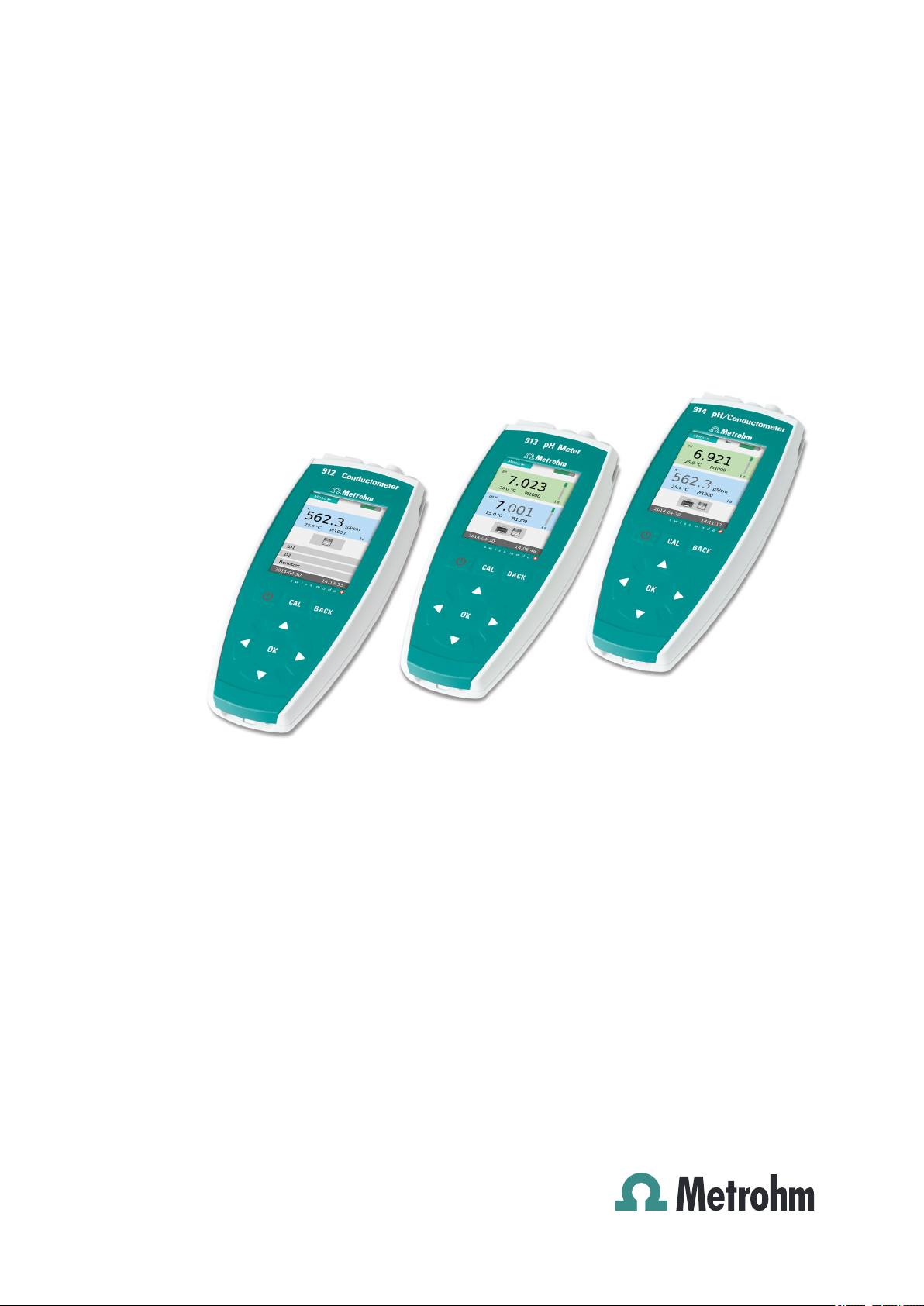
pH Meter/Conductometer
912 Conductometer | 913 pH Meter | 914 pH/Conductometer
Manual
8.912.8001EN / 2014-06-30
Page 2

Page 3

Metrohm AG
CH-9100 Herisau
Switzerland
Phone +41 71 353 85 85
Fax +41 71 353 89 01
info@metrohm.com
www.metrohm.com
pH Meter/Conductometer
912 Conductometer | 913 pH Meter |
914 pH/Conductometer
8.912.8001EN / 2014-06-30
Manual
fpe
Page 4

Teachware
Metrohm AG
CH-9100 Herisau
teachware@metrohm.com
This documentation is protected by copyright. All rights reserved.
Although all the information given in this documentation has been
checked with great care, errors cannot be entirely excluded. Should you
notice any mistakes please send us your comments using the address
given above.
Documentation in additional languages can be found on
http://documents.metrohm.com.
Page 5

■■■■■■■■■■■■■■■■■■■■■■
Table of contents
1 Introduction 1
1.1 Instrument description ......................................................... 1
1.1.1 Model and sales versions ......................................................... 2
1.1.2 Power supply ........................................................................... 2
1.1.3 Interfaces ................................................................................ 3
1.1.4 Sensors .................................................................................... 3
1.2 Intended use ......................................................................... 3
1.3 About the documentation ................................................... 3
1.3.1 Symbols and conventions ........................................................ 3
1.4 Safety instructions ................................................................ 4
1.4.1 General notes on safety ........................................................... 4
1.4.2 Electrical safety ........................................................................ 5
1.4.3 Flammable solvents and chemicals ........................................... 6
1.4.4 Recycling and disposal ............................................................. 6
Table of contents
2 Overview of the instrument 7
2.1 Instrument connectors ......................................................... 8
2.1.1 912 Conductometer ................................................................ 8
2.1.2 913 pH Meter .......................................................................... 8
2.1.3 914 pH/Conductometer IS ....................................................... 9
2.1.4 914 pH/Conductometer ........................................................... 9
2.2 Application environment ................................................... 10
2.2.1 Laboratory use ....................................................................... 10
2.2.2 Mobile application ................................................................. 11
3 Installation 12
3.1 Unpacking and inspecting the instrument ....................... 12
3.1.1 Packaging .............................................................................. 12
3.1.2 Checks .................................................................................. 12
3.1.3 Scope of application .............................................................. 12
3.2 Power supply ...................................................................... 12
3.2.1 Charging the battery .............................................................. 13
3.2.2 Operation with power supply unit ......................................... 14
3.2.3 Operation via USB connector (PC) .......................................... 15
3.3 Connecting sensors ............................................................ 15
pH Meter/Conductometer
3.4 Connecting a printer .......................................................... 16
3.5 Initial configuration ............................................................ 16
3.5.1 Setting the Language ............................................................. 16
3.5.2 Setting the date and time ...................................................... 17
3.6 Installing updates ............................................................... 19
■■■■■■■■
III
Page 6

Table of contents
■■■■■■■■■■■■■■■■■■■■■■
4 Operation 21
4.1 Switching the instrument on and off ............................... 21
4.2 Displays ............................................................................... 21
4.3 Status displays .................................................................... 24
4.3.1 Battery status ........................................................................ 24
4.3.2 User rights ............................................................................. 24
4.3.3 Sensor quality for pH electrodes ............................................ 25
4.4 Control keys ........................................................................ 25
4.5 Basic operation ................................................................... 26
4.5.1 Main dialog with two measuring channels ............................. 26
4.5.2 Main dialog with one measuring channel ............................... 27
4.5.3 Operation in the main dialog ................................................. 28
4.5.4 Menu dialog .......................................................................... 29
4.5.5 Editing dialog ........................................................................ 30
4.5.6 Selection dialog ..................................................................... 32
4.6 Menu structures .................................................................. 33
4.6.1 912 Conductometer .............................................................. 34
4.6.2 913 pH Meter ........................................................................ 35
4.6.3 914 pH/Conductometer IS ..................................................... 36
4.6.4 914 pH/Conductometer ......................................................... 37
4.7 Menu dialogs ...................................................................... 38
4.7.1 Parameters pH/U/T and Parameters pH/U/T IS ........................ 38
4.7.2 Parameters Κ/TDS/Sal/ρ/T ...................................................... 39
4.7.3 Measured values .................................................................... 40
4.7.4 Sensors .................................................................................. 42
4.7.5 Report ................................................................................... 47
4.7.6 Configuration ........................................................................ 48
4.7.7 User ...................................................................................... 49
4.8 pH measurement ................................................................ 50
4.8.1 pH electrode calibration ......................................................... 50
4.8.2 Measurement ........................................................................ 52
4.9 Conductivity measurement ................................................ 53
4.9.1 Determination of the cell constant (calibration) ...................... 53
4.9.2 Measurement ........................................................................ 54
4.10 Outputting reports/measured values ................................ 56
4.10.1 Printing out ........................................................................... 56
4.10.2 PC/LIMS and CSV data transfer .............................................. 56
5 Operation and maintenance 59
5.1 General notes ...................................................................... 59
5.1.1 Care ...................................................................................... 59
5.1.2 Maintenance by Metrohm Service .......................................... 59
5.1.3 Sensor care ............................................................................ 59
■■■■■■■■
IV
5.2 Quality management and qualification with Metrohm .. 60
pH Meter/Conductometer
Page 7

■■■■■■■■■■■■■■■■■■■■■■
6 Troubleshooting 61
7 Appendix 66
Table of contents
6.1 General ................................................................................ 61
6.2 Problems ............................................................................. 62
6.2.1 Troubleshooting .................................................................... 62
6.3 Restarting/resetting the instrument ................................. 64
6.3.1 Instrument reset .................................................................... 64
6.3.2 Resetting the instrument to factory settings ........................... 64
6.4 Messages ............................................................................. 65
7.1 Saved buffer series ............................................................. 66
7.1.1 Metrohm ............................................................................... 67
7.1.2 NIST (according to DIN standard 19266, 2000) ...................... 68
7.1.3 DIN (according to DIN standard 19267, 2012) ....................... 69
7.1.4 Fisher .................................................................................... 70
7.1.5 Mettler Toledo ....................................................................... 71
7.1.6 Merck CertiPUR 20 / Titrisol ................................................... 72
7.1.7 Merck CertiPUR 25 ................................................................ 73
7.1.8 Beckmann ............................................................................. 74
7.1.9 Radiometer ............................................................................ 75
7.1.10 Baker ..................................................................................... 76
7.1.11 Hamilton DURACAL ............................................................... 77
7.1.12 Fluka ..................................................................................... 78
8 Technical specifications 79
8.1 Measuring inputs ................................................................ 79
8.2 Measured value memory ................................................... 80
8.3 TFT display .......................................................................... 80
8.4 Interfaces ............................................................................. 80
8.5 Power supply ...................................................................... 80
8.6 Charging time ..................................................................... 81
8.7 Runtime with battery ......................................................... 81
8.8 Housing specification ......................................................... 82
8.9 Safety specification ............................................................ 82
8.10 Electromagnetic compatibility (EMC) ................................ 82
8.11 Ambient temperature ......................................................... 83
8.12 Reference conditions .......................................................... 83
8.13 Dimensions/material ........................................................... 83
9 Warranty (guarantee) 84
pH Meter/Conductometer
■■■■■■■■
V
Page 8

Table of contents
■■■■■■■■■■■■■■■■■■■■■■
10 Accessories 86
Glossary 88
Index 89
■■■■■■■■
VI
pH Meter/Conductometer
Page 9

■■■■■■■■■■■■■■■■■■■■■■
Table of figures
Figure 1 pH Meter/Conductometer - front ...................................................... 7
Figure 2 912 Conductometer - connectors ...................................................... 8
Figure 3 913 pH Meter - connectors ............................................................... 8
Figure 4 914 pH/Conductometer (digital) - connectors .................................... 9
Figure 5 914 pH/Conductometer (analog) - connectors ................................... 9
Figure 6 pH Meter/Conductometer in a laboratory setup ............................... 10
Figure 7 pH Meter/Conductometer for mobile application ............................. 11
Figure 8 USB Y cable ..................................................................................... 16
Figure 9 View - main dialog .......................................................................... 22
Figure 10 View - menu dialog ......................................................................... 22
Figure 11 View - editing dialog ....................................................................... 23
Figure 12 View - selection dialog .................................................................... 23
Figure 13 Operation - main dialog, two-channel ............................................. 27
Figure 14 Operation - main dialog, one-channel ............................................. 28
Figure 15 Operation - menu dialog ................................................................. 30
Figure 16 Operation - editing dialog ............................................................... 31
Figure 17 Operation - selection dialog ............................................................. 32
Figure 18 Example of a message ..................................................................... 65
Table of figures
pH Meter/Conductometer
■■■■■■■■
VII
Page 10

Page 11

■■■■■■■■■■■■■■■■■■■■■■
1 Introduction
This manual gives you a comprehensive overview of the installation, function and operation of pH Meter/Conductometer instruments.
NOTE
You can request application descriptions in the form of
Application Notes and Application Bulletins from your
Metrohm representative or download them from
http://www.metrohm.com.
1.1 Instrument description
pH Meter/Conductometer instruments are designed for use both outdoors and indoors as well as for stationary use in the laboratory.
1 Introduction
The instruments come in four basic versions, which differ in their design
with regard to different measuring channels and respective functions.
912 Conductometer
913 pH Meter With an analog and a digital measuring channel each for measuring the
914 pH/Conductometer IS
914 pH/Conductometer
With a measuring channel for measuring the conductivity, the TDS and
the salinity.
pH value, the potential and the temperature.
With a digital measuring channel for measuring the pH value, the potential and the temperature and a measuring channel for measuring the conductivity, the TDS, the salinity and the temperature.
With an analog measuring channel for measuring the pH value, the potential and the temperature and a measuring channel for measuring the conductivity, the TDS, the salinity and the temperature.
pH Meter/Conductometer
■■■■■■■■
1
Page 12
1.1 Instrument description
1.1.1 Model and sales versions
pH Meter/Conductometer instruments are available in the following
versions:
Table 1 Model versions
2.912.0010 912 Conductometer Instrument with standard
2.912.0110 912 Conductometer Mobile version with acces-
2.912.0210 912 Conductometer Laboratory version with
2.913.0010 913 pH Meter (digital/analog) Instrument with standard
2.913.0110 913 pH Meter (digital/analog) Mobile version with acces-
2.913.0210 913 pH Meter (digital/analog) Laboratory version with
■■■■■■■■■■■■■■■■■■■■■■
accessories
sories case
instrument base console
accessories
sories case
instrument base console
2.914.0010 914 pH/Conductometer (pH digital) Instrument with standard
2.914.0020 914 pH/Conductometer (pH analog) Instrument with standard
2.914.0110 914 pH/Conductometer (pH digital) Mobile version with acces-
2.914.0120 914 pH/Conductometer (pH analog) Mobile version with acces-
2.914.0210 914 pH/Conductometer (pH digital) Laboratory version with
2.914.0220 914 pH/Conductometer (pH analog) Laboratory version with
The accessories for a given instrument version can be created as a PDF
list on the Internet at http://partslists.metrohm.com.
1.1.2 Power supply
The instrument is powered either by a built-in battery or, in stationary use,
via a power supply unit.
accessories
accessories
sories case
sories case
instrument base console
instrument base console
NOTE
■■■■■■■■
2
pH Meter/Conductometer
Page 13
■■■■■■■■■■■■■■■■■■■■■■
1.1.3 Interfaces
You can connect a printer or establish a connection with a PC for data
transfer (PC/LIMS report and CSV format) using the USB interface.
1.1.4 Sensors
Metrohm offers various sensors for specific measurements.
For more information on the theoretical background, please refer to the
Metrohm monograph Electrodes in Potentiometry.
1.2 Intended use
This instrument is suitable for measuring in chemicals and flammable samples. Usage of the pH Meter/Conductometer therefore requires the user to
have basic knowledge and experience in handling toxic and caustic substances. Knowledge with respect to the application of the fire prevention
measures prescribed for laboratories is also mandatory.
1 Introduction
NOTE
1.3 About the documentation
CAUTION
Please read through this documentation carefully before putting the
instrument into operation. The documentation contains information
and warnings which the user must follow in order to ensure safe operation of the instrument.
1.3.1 Symbols and conventions
The following symbols and formatting may appear in this documentation:
Cross-reference to figure legend
The first number refers to the figure number, the second to the instrument part in the figure.
Instruction step
Carry out these steps in the sequence shown.
Method Dialog text, parameter in the software
pH Meter/Conductometer
■■■■■■■■
3
Page 14
1.4 Safety instructions
■■■■■■■■■■■■■■■■■■■■■■
File ▶ New Menu or menu item
[Next] Button or key
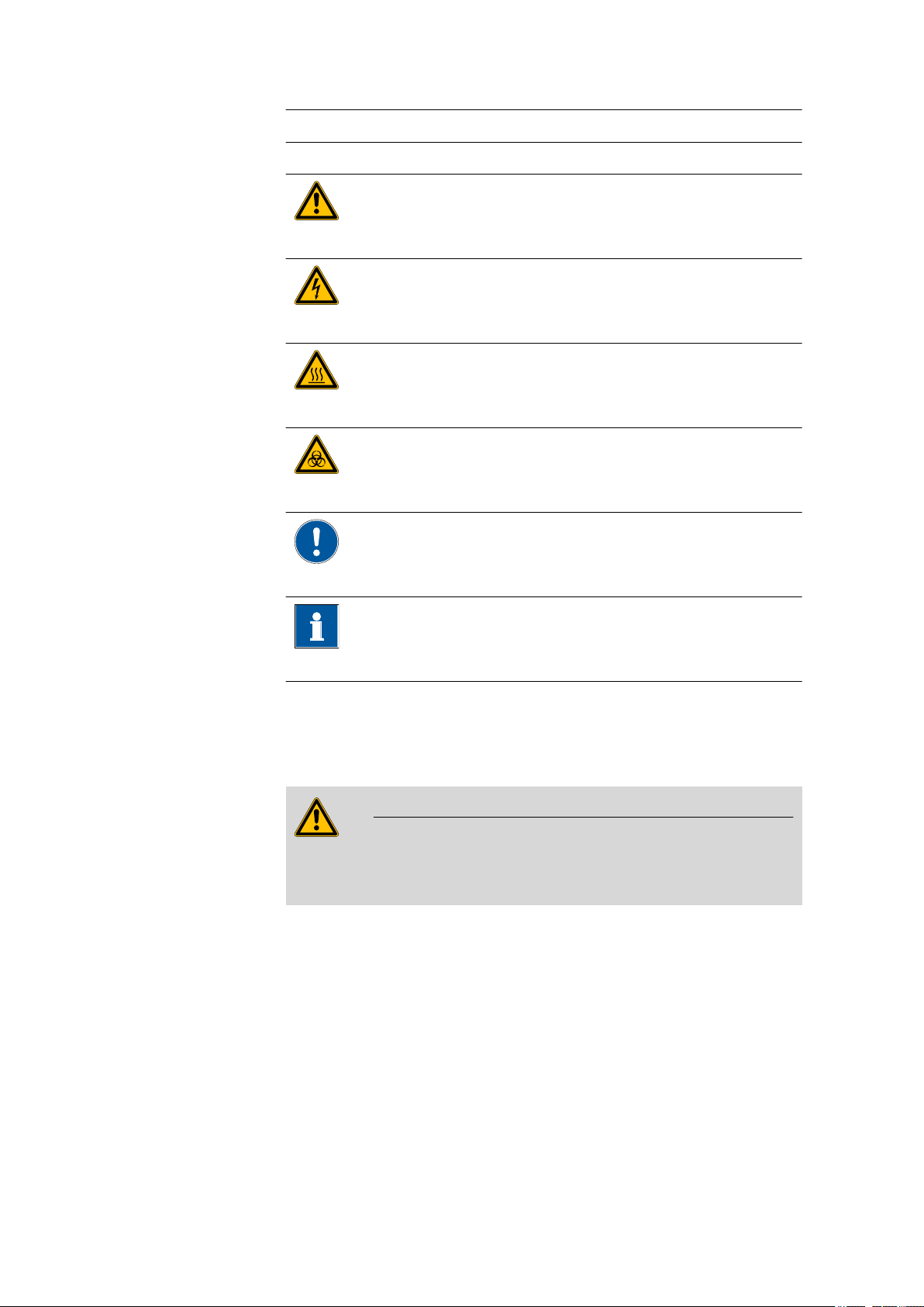
WARNING
This symbol draws attention to a possible life-threatening hazard or risk of injury.
WARNING
This symbol draws attention to a possible hazard due
to electrical current.
WARNING
This symbol draws attention to a possible hazard due
to heat or hot instrument parts.
WARNING
This symbol draws attention to a possible biological
hazard.
1.4 Safety instructions
1.4.1 General notes on safety
WARNING
This instrument may only be operated in accordance with the specifications in this documentation.
This instrument has left the factory in a flawless state in terms of technical
safety. To maintain this state and ensure non-hazardous operation of the
instrument, the following instructions must be observed carefully.
CAUTION
This symbol draws attention to possible damage to
instruments or instrument parts.
NOTE
This symbol highlights additional information and
tips.
■■■■■■■■
4
pH Meter/Conductometer
Page 15
■■■■■■■■■■■■■■■■■■■■■■
1.4.2 Electrical safety
The electrical safety when working with the instrument is ensured as part
of the international standard IEC 61010.
Only personnel qualified by Metrohm are authorized to carry out service
work on electronic components.
Never open the housing of the instrument. The instrument could be
damaged by this. There is also a risk of serious injury if live components
are touched.
There are no parts inside the housing which can be serviced or replaced
by the user.
1 Introduction
WARNING
WARNING
Supply voltage
WARNING
An incorrect mains voltage can damage the instrument.
Only operate this instrument with a mains voltage specified for it (see
rear panel of the instrument).
Battery / power supply unit
WARNING
Use the power supply unit only for its intended purpose. Inappropriate
use or use of non-approved or incompatible power supply units may
cause fires or explosions and result in the revocation of the license or
warranty.
If you think that the battery or the power supply unit has been damaged, have it checked by a service center. Do not use damaged batteries or power supply units.
pH Meter/Conductometer
Do not charge your instrument during thunderstorms.
Do not use the power supply unit outdoors.
■■■■■■■■
5
Page 16
1.4 Safety instructions
1.4.3 Flammable solvents and chemicals
WARNING
All relevant safety measures are to be observed when working with
flammable solvents and chemicals.
■ Set up the instrument in a well-ventilated location (e.g. fume cup-
board).
■ Keep all sources of flame far from the workplace.
■ Clean up spilled liquids and solids immediately.
■ Follow the safety instructions of the chemical manufacturer.
1.4.4 Recycling and disposal
This product is covered by European Directive 2002/96/EC, WEEE – Waste
from Electrical and Electronic Equipment.
The correct disposal of your old equipment will help to prevent negative
effects on the environment and public health.
■■■■■■■■■■■■■■■■■■■■■■
More details about the disposal of your old equipment can be obtained
from your local authorities, from waste disposal companies or from your
local dealer.
■■■■■■■■
6
pH Meter/Conductometer
Page 17
■■■■■■■■■■■■■■■■■■■■■■
2 Overview of the instrument
2 Overview of the instrument
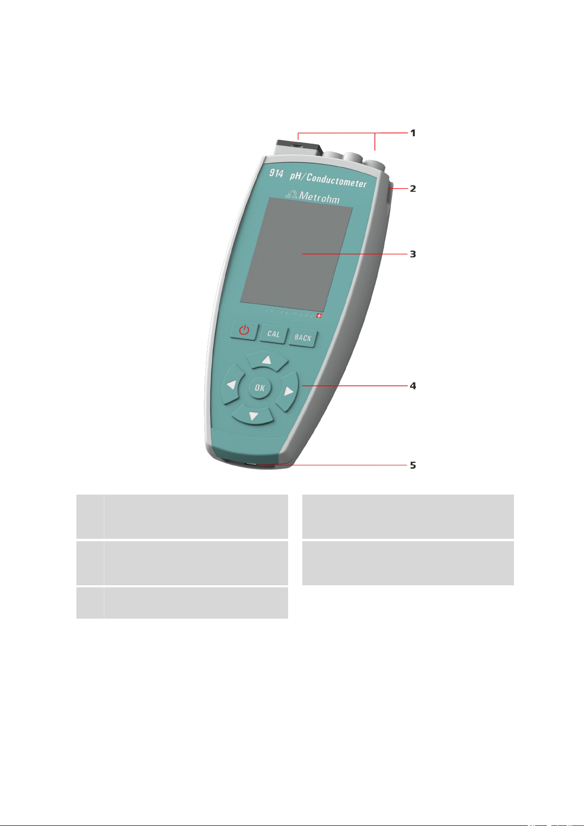
Figure 1 pH Meter/Conductometer - front
Connectors / interfaces
1
With a cover cap for the USB interface and
the digital interface.
Display
3
For measured values and menus (see Chapter 4.2, page 21).
Eyelet for carrying strap
5
As accessory for mobile applications.
pH Meter/Conductometer
Sensor holder slot
2
For mobile applications, a sensor holder may
be inserted here.
Keypad
4
With a total of eight keys to operate the
instrument (see Chapter 4.4, page 25).
■■■■■■■■
7
Page 18
2.1 Instrument connectors
2.1 Instrument connectors
2.1.1 912 Conductometer
Figure 2 912 Conductometer - connectors
■■■■■■■■■■■■■■■■■■■■■■
Conductivity measuring cell
1
Connection socket for conductivity measuring cells.
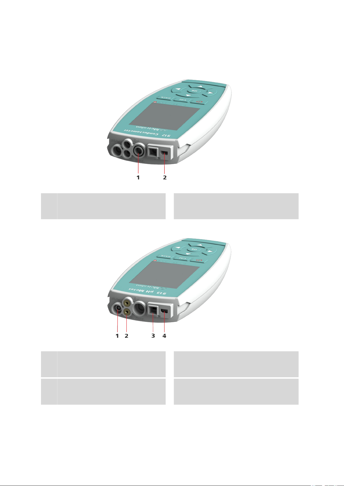
2.1.2 913 pH Meter
Figure 3
pH/mV electrode
1
Connection socket for analog pH/mV electrodes.
Type B mini USB connector
2
Connection socket for power supply, data
transmission and printing.
913 pH Meter - connectors
Temperature sensor / reference
2
3
■■■■■■■■
8
pH/mV electrode
Connection socket for 854 iConnect for
connecting iTrodes.
Type B mini USB connector
4
Connection socket for power supply, data
transmission and printing.
pH Meter/Conductometer
Page 19

■■■■■■■■■■■■■■■■■■■■■■
2.1.3 914 pH/Conductometer IS
Figure 4 914 pH/Conductometer (digital) - connectors
2 Overview of the instrument
Conductivity measuring cell
1
Connection socket for conductivity measuring cells.
Type B mini USB connector
3
Connection socket for power supply, data
transmission and printing.
2.1.4 914 pH/Conductometer
pH/mV electrode
2
Connection socket for 854 iConnect for
connecting iTrodes.
Figure 5
pH/mV electrode
1
Connection socket for analog pH/mV electrodes.
Conductivity measuring cell
3
Connection socket for conductivity measuring cells.
pH Meter/Conductometer
914 pH/Conductometer (analog) - connectors
Temperature sensor / reference
2
Type B mini USB connector
4
Connection socket for power supply, data
transmission and printing.
■■■■■■■■
9
Page 20
2.2 Application environment
2.2 Application environment
pH Meter/Conductometer instruments have been designed for use in
laboratories and for mobile use indoors or outdoors.
The sturdy design meets the requirements in accordance with IP 67 protection marking. The instruments are therefore protected against shorttime immersion in water, provided that the respective plugs are plugged in
at the sensor connectors.
2.2.1 Laboratory use
In the laboratory, pH Meter/Conductometer instruments can be placed
in an instrument base console.
■■■■■■■■■■■■■■■■■■■■■■
■■■■■■■■
10
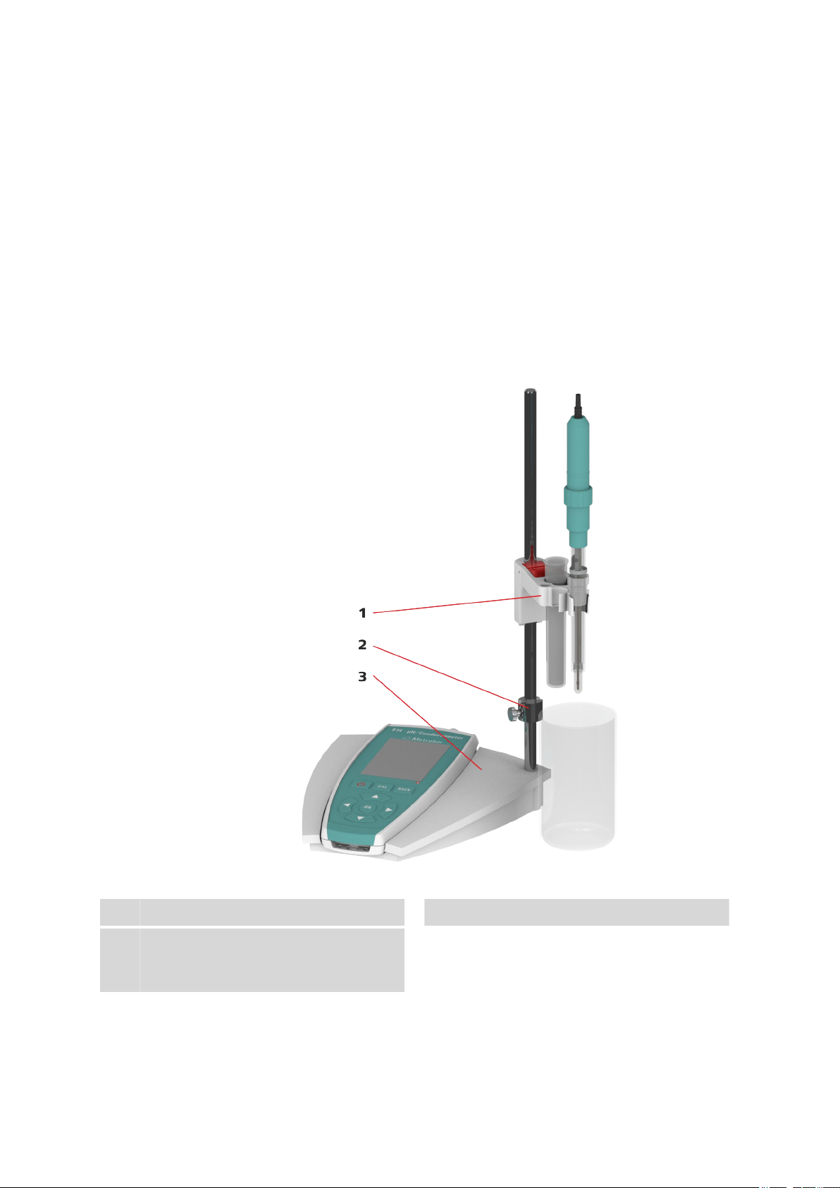
Figure 6
Electrode holder
1
Instrument base console
3
Consisting of receptacle base and support
rod.
pH Meter/Conductometer in a laboratory setup
Clamping ring
2
pH Meter/Conductometer
Page 21
■■■■■■■■■■■■■■■■■■■■■■
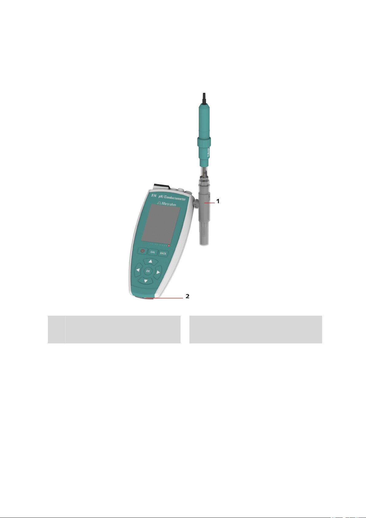
2.2.2 Mobile application
For mobile application, pH Meter/Conductometer instruments can be
equipped with a carrying strap and one or two slide-in holders for electrodes.
2 Overview of the instrument
Figure 7 pH Meter/Conductometer for mobile application
Electrode holder
1
The holders can be inserted from both sides
(left/right) of the instrument.
pH Meter/Conductometer
Eyelet for carrying strap
2
■■■■■■■■
11
Page 22
3.1 Unpacking and inspecting the instrument
■■■■■■■■■■■■■■■■■■■■■■
3 Installation
3.1 Unpacking and inspecting the instrument
3.1.1 Packaging
The instrument is supplied in highly protective special packaging together
with the separately packed accessories. Keep this packaging, as only this
ensures safe transportation of the instrument.
3.1.2 Checks
Immediately after receipt, check whether the shipment has arrived complete and without damage by comparing it with the delivery note.
3.1.3 Scope of application
pH Meter/Conductometer instruments have been designed for mobile
application outdoors and/or in the laboratory.
Influence of weather conditions
Damage to instruments as a result of sun irradiation or temperatures
below the freezing point.
When you do not use the instrument, do not expose it to direct sunlight and to temperatures below 0 °C.
3.2 Power supply
The pH Meter/Conductometer is equipped with a built-in battery and
can thus be used for mobile applications. For stationary use in the laboratory, the instrument can be operated with a power supply unit.
Battery state of charge
You receive the battery in a partially charged state. However, you may
have to recharge it again before you can use the instrument for the first
time.
CAUTION
NOTE
■■■■■■■■
12
pH Meter/Conductometer
Page 23
■■■■■■■■■■■■■■■■■■■■■■
3 Installation
CAUTION
Unauthorized manipulations
The instrument may be damaged as a result of unauthorized manipulations.
■ Use for charging only the supplied power supply unit (6.2166.100)
or the optional car charger adapter (6.2166.500), which have been
approved as accessories for use with this instrument.
■ Your instrument's battery cannot be removed.
■ Do not attempt to remove the battery from the instrument. To
replace the battery, take the instrument to your nearest authorized
Metrohm Service.
■ Unauthorized replacement of the battery may result in a loss of the
warranty.
NOTE
Function of the control keys
For the installation steps below you need to use the control keys.
These are described in the following Operation chapter (see Chapter
4.4, page 25).
3.2.1 Charging the battery
NOTE
Charging the battery
The battery is charged only when the instrument is switched on.
Please observe the following procedure:
1. First, connect the USB cable to the supplied power supply unit, then
the power supply unit to the socket, and then finally the mini USB
connector of the cable to your instrument.
2. Now switch on the instrument using the key.
3. When the battery is fully charged, disconnect the power supply unit
first from the instrument and then from the socket.
pH Meter/Conductometer
or
■■■■■■■■
13
Page 24
3.2 Power supply
■■■■■■■■■■■■■■■■■■■■■■
If no power socket is available, you can also charge your instrument via
the USB interface of a computer (PC) or a car charger adapter.
NOTE
Charging capacity
The charging process requires a minimum capacity of 500 mAh.
■ Use a USB hub with external power supply or a suitable USB connec-
tor on the computer (PC).
■ For mobile charging of the battery, use a car charger adapter from
the Metrohm accessories (6.2166.500).
1. Connect the USB cable first to the computer and then to your instrument.
2. Then switch on the instrument.
3. As soon as the battery is fully charged, disconnect the USB cable first
from the instrument and then from the computer.
NOTE
Battery condition
The battery performance may deteriorate over time. If the operating
times are much shorter than usual, take the instrument to the closest
Metrohm Service to have the battery replaced.
3.2.2 Operation with power supply unit
You can operate the pH Meter/Conductometer with the supplied
power supply unit without restrictions.
CAUTION
Measuring with power supply unit connected
Inappropriate power supply units may influence and interfere with the
measuring signal.
Use only the supplied power supply unit (6.2166.100) for measuring.
■■■■■■■■
14
pH Meter/Conductometer
Page 25
■■■■■■■■■■■■■■■■■■■■■■
NOTE
Charging the battery with power supply
The battery will not be overcharged if the instrument is used for
extended periods with the power supply unit connected. The instrument is equipped with a charging controller to protect the battery.
3.2.3 Operation via USB connector (PC)
Operation of the instrument with power supply via a USB connector
requires a minimum capacity of 500 mAh (see Chapter 3.2.1, page 13).
3.3 Connecting sensors
Sensors can be connected while the instrument is running.
NOTE
3 Installation
Parameter setting
Please note that if you change the sensor the sensor has to be selected
in the menu dialog Menu ▶ Parameters X ▶ Measuring parame-
ters ▶ Sensor name or a new sensor has to be entered in the sensor
list.
NOTE
iConnect for iTrodes
Sensors from the iTrodes line are only supported by the 854 iConnect series 07 or higher.
The series is indicated by the number 17 in the following serial number
example:
1854001017216
pH Meter/Conductometer
■■■■■■■■
15
Page 26
3.4 Connecting a printer
3.4 Connecting a printer
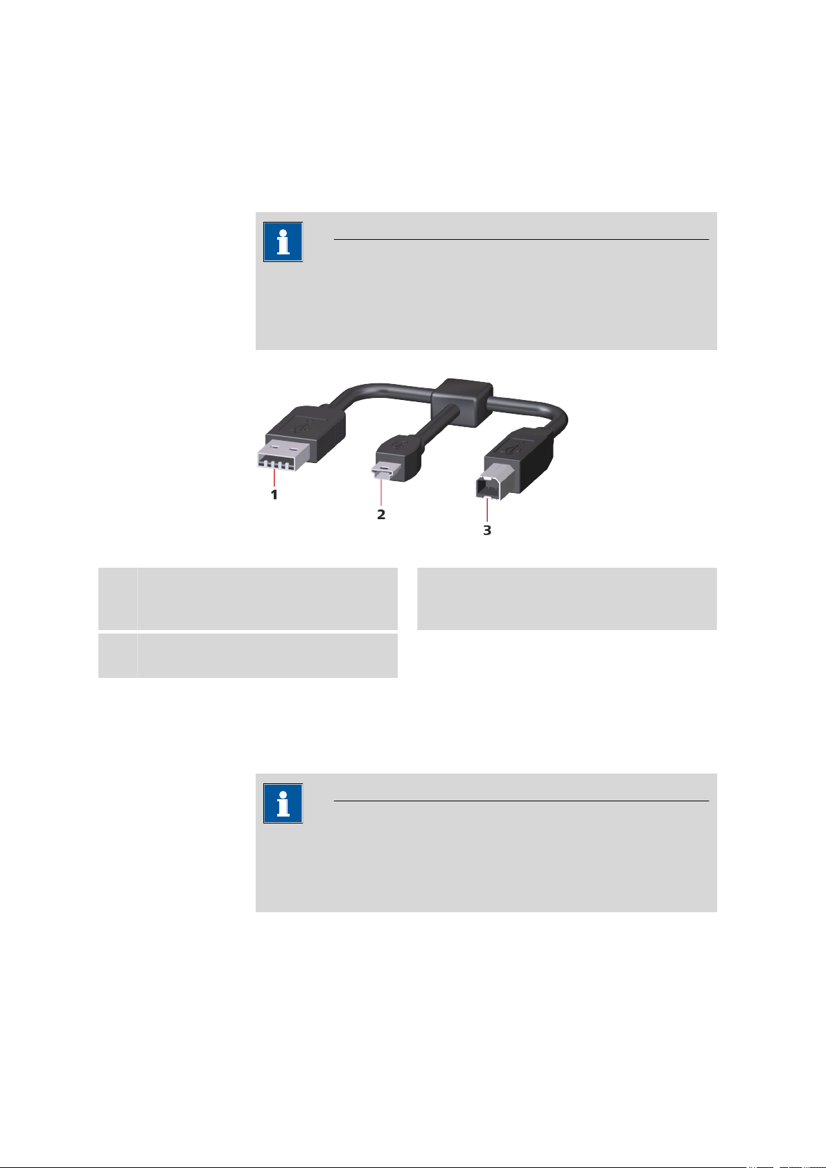
Printers for report output are connected with the USB Y cable
(6.2151.140).
NOTE
Printer function
The connected printer works only when the
pH Meter/Conductometer is supplied by the power supply unit.
■■■■■■■■■■■■■■■■■■■■■■
Figure 8
USB type A
1
Power supply unit connector for power supply.
USB type B
3
Printer connector.
USB Y cable
3.5 Initial configuration
3.5.1 Setting the Language
NOTE
"Language" factory setting
On instruments delivered ex works, English is set in the language settings.
The following languages are available on the instrument:
USB type B mini
2
Instrument connector pH Meter/Conductometer.
■■■■■■■■
16
■ German
■ English
pH Meter/Conductometer
Page 27
■■■■■■■■■■■■■■■■■■■■■■
3 Installation
■ Spanish
■ French
■ Portuguese
■ Chinese
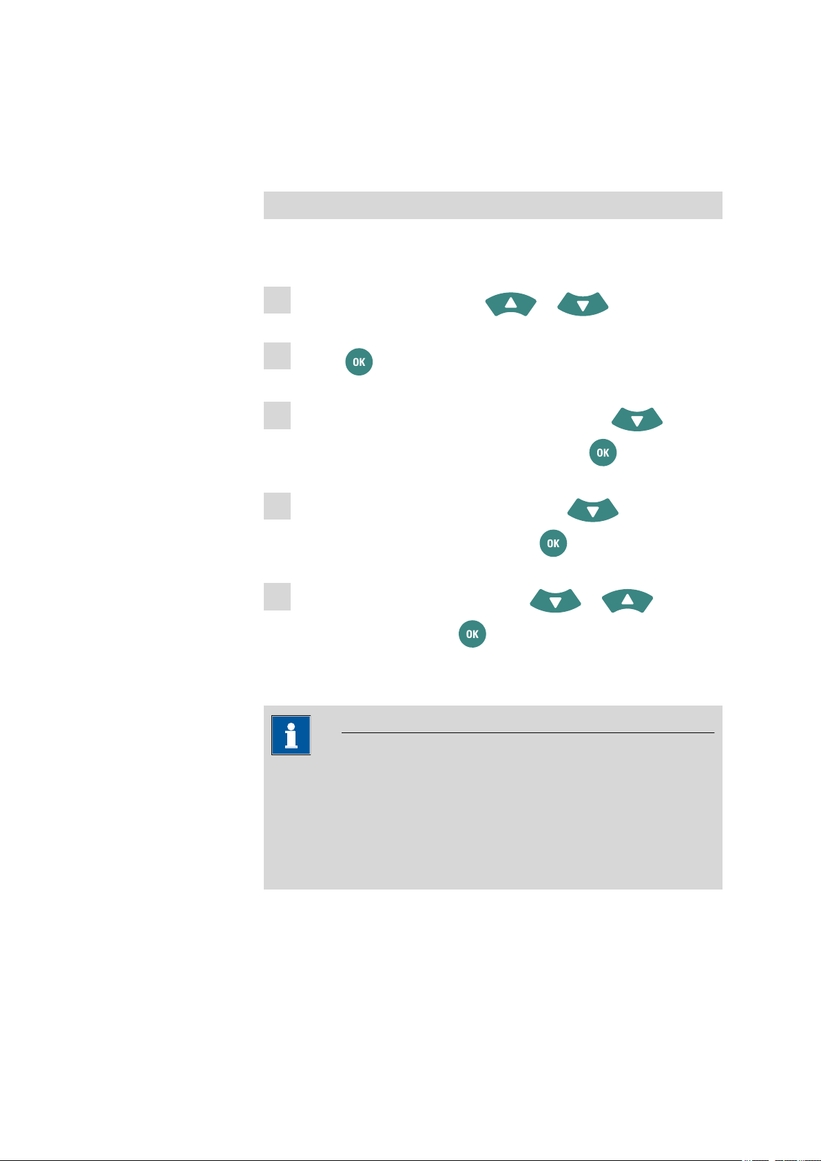
Setting the Language
You can access the menu structures via the Menu item (see Figure 13,
page 27) in the main screen.
1
Select the entry point with the or arrow keys.
2
Use the key to change to the menu structures.
3
Select the Configuration menu structure with the arrow
key and change to the menu structure with the key.
4
Select the Language menu dialog with the arrow key and
change to the selection dialog with the key.
5
Select the required language with the or arrow
keys and confirm with the key.
3.5.2 Setting the date and time
NOTE
"Date/time" factory setting
The date and time values of the manufacturer are set on the instruments ex works.
In case of deep discharge of the battery, the system time will be reset
to the default value.
pH Meter/Conductometer
■■■■■■■■
17
Page 28

3.5 Initial configuration
■■■■■■■■■■■■■■■■■■■■■■
Setting the date/time
You can access the menu structures via the Menu item (see Figure 13,
page 27) in the main screen.
1
Select the entry point with the or arrow keys.
2
Use the key to change to the menu structures.
3
Select the Configuration menu structure with the arrow
key and change to the menu structure with the key.
4
Select the Date or the Time menu dialog with the arrow
key and change to the editing dialog with the key.
■ Date format: YYYY-MM-DD
■ Time format: hh:mm:ss
5
Select the required character with the , , , and
arrow keys and confirm each with the key.
6
Confirm the final value with the editing element and the
key.
■■■■■■■■
18
pH Meter/Conductometer
Page 29

■■■■■■■■■■■■■■■■■■■■■■
3.6 Installing updates
Stay up to date – download the latest versions of the software and programs to your pH Meter/Conductometer to benefit from new and
expanded functions. The performance of your instrument may also be
improved by software updates.
Downloading the update from the Internet
First, you have to download the data for the instrument update from the
Internet and save it on the computer (PC).
Go to http://www.metrohm.com/com/Support/Software.html.
1
Select the instrument in the list box.
2
Select the appropriate software version and save it somewhere on
3
your computer.
Extract the zip file. The two files in the SwUpdates subfolder with
4
the suffixes *.bin and *.mbin will be used for the installation.
3 Installation
NOTE
Data backup
You are recommended to create a backup of the saved data before the
update.
Use the Print out or Data transfer functions (see Chapter 4.10, page
56).
Installing the update on the instrument
For the actual installation of the update, the instrument has to be connected to the computer (PC) by means of a USB cable (6.2151.110).
The optional USB Y cable (6.2151.140) cannot be used.
Connect the USB cable to the computer and then to the instrument.
1
Switch on the instrument.
2
pH Meter/Conductometer
■■■■■■■■
19
Page 30

3.6 Installing updates
■■■■■■■■■■■■■■■■■■■■■■
NOTE
Switching on the instrument
The USB connection works only when the instrument is on.
The instrument is recognized by the computer (PC) as a removable
drive.
Copy the two files with the suffixes *.bin and *.mbin directly into
3
the root directory of the instrument (removable drive) using a file
manager (e.g. Windows Explorer).
Switch off the instrument after the copy process has been completed
4
and disconnect it from the USB cable.
Switch on the instrument again and wait for the installation process.
5
During start-up, the instrument recognizes the new update files and
installs these automatically.
■■■■■■■■
20
pH Meter/Conductometer
Page 31

■■■■■■■■■■■■■■■■■■■■■■
4 Operation
4.1 Switching the instrument on and off
Switching on the instrument
Proceed as follows to do this:
1
Press the key.
The instrument is initialized and a system test is performed. This process takes some time.
A starting image is displayed during start-up.
Then the main dialog is displayed. Now the instrument is ready.
4 Operation
4.2 Displays
Switching off the instrument
1
Press the key.
The message 912-129 Shut down appears and the instrument
saves the data and turns off.
The pH Meter/Conductometer has a total of four display types containing specific displays and/or operating functions.
■ Main dialog
■ Menu dialog
■ Editing dialog
■ Selection dialog
NOTE
Active dialog field
pH Meter/Conductometer
The actively selected dialog field is always displayed with the Metrohm
green contrast color.
In this case, the entry point for the Menu menu structures is selected.
■■■■■■■■
21
Page 32

4.2 Displays
■■■■■■■■■■■■■■■■■■■■■■
Main dialog The main dialog (example: both measuring channels displayed) is the nor-
mal status after the instrument has been switched on.
Figure 9 View - main dialog
Menu dialog The menu dialog is used for navigating through the functional structures.
Menu lines with an arrow contain another, deeper structure with further
dialogs.
Figure 10 View - menu dialog
Editing dialog Editing dialogs are used in general for data entry and editing.
Depending on the data type, a different set of possible characters is available.
■■■■■■■■
22
pH Meter/Conductometer
Page 33

■■■■■■■■■■■■■■■■■■■■■■
4 Operation
NOTE
Capital letters and special characters
You can insert capital letters and special characters by holding the
key.
Figure 11 View - editing dialog
Selection dialog Selection dialogs offer preset values for selection in corresponding data
fields.
Figure 12 View - selection dialog
pH Meter/Conductometer
■■■■■■■■
23
Page 34

4.3 Status displays
4.3 Status displays
The main dialog displays contain corresponding graphical elements to
show instrument and sensor statuses.
4.3.1 Battery status
The battery status is displayed in five stages with colored graphical elements.
The battery is full and charging is complete.
The battery is nearly full but still charging.
The battery is charged to 75%.
The battery is charged to 50%.
The battery is charged to 25%.
■■■■■■■■■■■■■■■■■■■■■■
4.3.2 User rights
The battery is empty.
NOTE
Flash icon
The flash icon indicates that the instrument is connected to a power
source for charging.
The user rights can be set in the Menu under User as Dialog type:
1. Expert
Use of the instrument is unrestricted. All functions are available.
2. Routine
The menu structures Configuration and Sensors are locked.
If the key icon
menu is limited to the functions for Routine users.
(on top in the main dialog) is displayed, then the user
■■■■■■■■
24
pH Meter/Conductometer
Page 35

■■■■■■■■■■■■■■■■■■■■■■
4.3.3 Sensor quality for pH electrodes
The sensor quality is indicated with three colored graphical elements.
The criteria for the display status are set in the calibration parameters (see
Chapter 4.7.4, page 42).
The electrode is in a good range with regard to the limit values set.
The electrode is close to the limit value range.
The limit value range is defined as follows:
■ Slope limit value with an approximation of 1% to the set limit value.
■ Limit value pH(0) with an approximation of 0.1 pH to the set limit
value.
The electrode is outside the limit values.
4 Operation
4.4 Control keys
Keypad
Switching the instrument on or off.
■ To switch on, briefly push the key. The instrument turns on.
■ To switch off, briefly push the key. A message appears and the instru-
ment turns off.
The CAL key starts the procedure to calibrate a sensor.
pH Meter/Conductometer
■■■■■■■■
25
Page 36

4.5 Basic operation
■■■■■■■■■■■■■■■■■■■■■■
NOTE
Calibration
A sensor can only be calibrated in the corresponding one-channel main
dialog.
The BACK key causes the entry to be accepted and/or the dialog to be
exited.
The OK key confirms a selection or starts a process.
The LEFT/RIGHT arrow keys are used for navigation in the text and
number editor for selecting characters or for toggling between the measuring channel displays in the main dialog.
The UP/DOWN arrow keys are used for navigating the selection bar one
line up or down or for selecting characters in the text editor.
4.5 Basic operation
The following chapters describe the various displays and how to operate
them.
4.5.1 Main dialog with two measuring channels
The view with two measuring channels is displayed after the instrument
start-up.
NOTE
This does not apply for the 912 Conductometer, as this instrument
has only one measuring channel.
NOTE
Temperature display
The temperature displays on the two measuring channels can only be
compared in the same medium.
■■■■■■■■
26
As a result of temperature sensor and instrument tolerances, the displayed values might deviate from each other.
pH Meter/Conductometer
Page 37

■■■■■■■■■■■■■■■■■■■■■■
4 Operation
Figure 13 Operation - main dialog, two-channel
Battery state of charge
1
(see Chapter 4.3.1, page 24).
Sensor condition
3
(see Chapter 4.3.3, page 25).
Calibration interval display
5
Time in days until the next calibration is due.
Print/save measured value
7
Button for the functions print, save or
print+save.
Both measured values are printed and/or
saved.
The procedure for functions of the main dialog with two measuring
channels is the same as for the main dialog with one measuring channel:
■ (see "Accessing the menu structures", page 28).
■ (see "Toggling from one-channel to two-channel view", page 29).
NOTE
Menu access
2
(see "Accessing the menu structures", page
28).
Display measuring channel 1
4
Display measuring channel 2
6
Date/time display
8
4.5.2 Main dialog with one measuring channel
The corresponding measuring channel is displayed according to the selection.
In addition, the display and input fields ID1, ID2 and User are displayed in
the main dialog with one measuring channel.
pH Meter/Conductometer
■■■■■■■■
27
Page 38

4.5 Basic operation
■■■■■■■■■■■■■■■■■■■■■■
Figure 14 Operation - main dialog, one-channel
Battery state of charge
1
(see Chapter 4.3.1, page 24).
Sensor condition
3
(see Chapter 4.3.3, page 25).
Calibration interval display
5
Time in days until the next calibration is due.
ID1
7
Input option for sample designation/identification (e.g. name, number, etc.).
User
9
Input option for the user name or display of
the preset value from the User menu dialog
(see Chapter 4.7.7, page 49).
4.5.3 Operation in the main dialog
Menu access
2
(see "Accessing the menu structures", page
28).
Measuring channel display
4
Print/save measured value
6
Button for the functions print, save or
print+save.
The measured value with the currently
selected measuring channel is printed and/or
saved.
ID2
8
Input option for sample designation/identification (e.g. batch number, lot number, etc.).
Date/time display
10
■■■■■■■■
28
Accessing the menu structures
You can access the menu structures via the Menu item (14-2) in the main
dialog.
1
Select the entry point with the or arrow keys.
pH Meter/Conductometer
Page 39

■■■■■■■■■■■■■■■■■■■■■■
4 Operation
2
Use the key to change to the menu structures.
Toggling from one-channel to two-channel view
The view can be changed in instruments with two measuring channels.
Three views can be displayed as follows:
■ Display with both measuring channels.
■ Display with measuring channel 1 and the data ID1, ID2 and User.
■ Display with measuring channel 2 and the data ID1, ID2 and User.
1
You can toggle between the views as needed with the or
arrow keys.
Printing and/or saving measured values
Measured value recording is started with the Print/save measured
value button.
■
■ - Printing and saving the measured values.
■ - Saving the measured values.
The respective triggering is determined by the settings in the menu:
■ Menu ▶ Measured values ▶ Values
■ Menu ▶ Measured values ▶ Data
4.5.4 Menu dialog
The further menu structures, editing dialogs and selection dialogs can be
selected in the menu dialog.
- Printing the measured values.
and
(see Chapter 4.7.3, page 40).
pH Meter/Conductometer
■■■■■■■■
29
Page 40

4.5 Basic operation
■■■■■■■■■■■■■■■■■■■■■■
Figure 15 Operation - menu dialog
Menu title
1
The menu title indicates which menu structure is currently open.
Arrow icon
3
The arrow icon indicates that there are further substructures.
Navigation in the menu structures
You can access the menu structures via the Menu item (14-2) in the main
dialog.
1
Select the desired menu line with the or arrow
keys.
2
Change into the next substructure with the key.
3
Change back to the higher structure with the key.
Menu line selected
2
The selected menu line is always displayed in
the color Metrohm green and in inversed
text.
4.5.5 Editing dialog
■■■■■■■■
30
The entries can be created and edited again in the editing dialog.
pH Meter/Conductometer
Page 41

■■■■■■■■■■■■■■■■■■■■■■
4 Operation
Figure 16 Operation - editing dialog
Menu title
1
Data field
3
Function elements
5
Menu line
2
Selectable characters
4
The data entry is accepted with the Entry editing element.
The editing dialog is closed without changing the existing data value with
the Cancel editing element.
The entire contents of the data field are deleted and a new data value can
be entered with the Delete all editing element.
The character to the left of the cursor is deleted in the data field with the
Backspace editing element.
The cursor moves one space to the left in the data field with the One
space to the left editing element.
The cursor moves one space to the right in the data field with the One
space to the right editing element.
pH Meter/Conductometer
NOTE
Capital letters / special characters
Capital letters and special characters can be entered by holding the
key on the respective standard character.
■■■■■■■■
31
Page 42

4.5 Basic operation
4.5.6 Selection dialog
In selection dialogs, you can select and apply fixed data values.
Figure 17 Operation - selection dialog
■■■■■■■■■■■■■■■■■■■■■■
Menu title
1
Selectable data values
3
Menu line
2
Changing data values
The data values of the corresponding menu function can be selected, if
required.
On the corresponding menu function, open the selection window
1
with the key.
2
Select the required data value with the or arrow
keys.
3
Apply the data value and exit the selection window with the
key.
■■■■■■■■
32
pH Meter/Conductometer
Page 43

■■■■■■■■■■■■■■■■■■■■■■
4.6 Menu structures
pH Meter/Conductometer instruments contain different menu structures depending on the instrument version. These structures are represented in an overview in the following tables:
■ 912 Conductometer
(see Chapter 4.6.1, page 34)
■ 913 pH Meter
(see Chapter 4.6.2, page 35)
■ 914 pH/Conductometer IS
(see Chapter 4.6.3, page 36)
■ 914 pH/Conductometer
(see Chapter 4.6.4, page 37)
Menu dialogs
4 Operation
NOTE
The menu dialogs and the corresponding menu lines are described in
more detail in the next chapter (see Chapter 4.7, page 38).
pH Meter/Conductometer
■■■■■■■■
33
Page 44

4.6 Menu structures
4.6.1 912 Conductometer
Table 2 912 Conductometer – menu structures
■■■■■■■■■■■■■■■■■■■■■■
Menu Parameters Κ/TDS/Sal/ρ/T
(see Chapter 4.7.2, page 39)
Measured values
(see Chapter 4.7.3, page 40)
Sensors
(see Chapter 4.7.4, page 42)
Report
(see Chapter 4.7.5, page 47)
Configuration
(see Chapter 4.7.6, page 48)
■ Measuring parameters
■ Calibration param.
■ Values
■ Data
■ Criterion
■ Output date/time
■ Output headers
■ Calibration data
■ Sensor list
■ New sensor
■ Delete sensor
■ Report
■ Line feed
■ Printer
■ Last decimal place
■ Date
■ Time
■ Power off after
■ Turn off LCD after
■ Brightness
■ Program version
■ Language
■■■■■■■■
34
User
(see Chapter 4.7.7, page 49)
Service/Diagnosis
■ User
■ Dialog type
pH Meter/Conductometer
Page 45

■■■■■■■■■■■■■■■■■■■■■■
4.6.2 913 pH Meter
Table 3 913 pH Meter – menu structures
4 Operation
Menu Parameters pH/U/T
Parameters pH/U/T IS
(see Chapter 4.7.1, page 38)
Measured values
(see Chapter 4.7.3, page 40)
Sensors
(see Chapter 4.7.4, page 42)
Report
(see Chapter 4.7.5, page 47)
Configuration
(see Chapter 4.7.6, page 48)
■ Measuring parameters
■ Calibration param.
■ Values
■ Data
■ Criterion
■ Output date/time
■ Output headers
■ Calibration data
■ Sensor list
■ New sensor
■ Delete sensor
■ Report
■ Line feed
■ Printer
■ Last decimal place
■ Date
■ Time
■ Power off after
■ Turn off LCD after
■ Brightness
■ Program version
■ Language
pH Meter/Conductometer
User
(see Chapter 4.7.7, page 49)
Service/Diagnosis
■ User
■ Dialog type
■■■■■■■■
35
Page 46

4.6 Menu structures
4.6.3 914 pH/Conductometer IS
Table 4 914 pH/Conductometer IS – menu structures
■■■■■■■■■■■■■■■■■■■■■■
Menu Parameters pH/U/T IS
(see Chapter 4.7.1, page 38)
Parameters Κ/TDS/Sal/ρ/T
(see Chapter 4.7.2, page 39)
Measured values
(see Chapter 4.7.3, page 40)
Sensors
(see Chapter 4.7.4, page 42)
Report
(see Chapter 4.7.5, page 47)
Configuration
(see Chapter 4.7.6, page 48)
■ Measuring parameters
■ Calibration param.
■ Measuring parameters
■ Calibration param.
■ Values
■ Data
■ Criterion
■ Output date/time
■ Output headers
■ Calibration data
■ Sensor list
■ New sensor
■ Delete sensor
■ Report
■ Line feed
■ Printer
■ Last decimal place
■ Date
■ Time
■ Power off after
■ Turn off LCD after
■ Brightness
■ Program version
■ Language
■■■■■■■■
36
User
(see Chapter 4.7.7, page 49)
Service/Diagnosis
■ User
■ Dialog type
pH Meter/Conductometer
Page 47

■■■■■■■■■■■■■■■■■■■■■■
4.6.4 914 pH/Conductometer
Table 5 914 pH/Conductometer – menu structures
4 Operation
Menu Parameters pH/U/T
(see Chapter 4.7.1, page 38)
Parameters Κ/TDS/Sal/ρ/T
(see Chapter 4.7.2, page 39)
Measured values
(see Chapter 4.7.3, page 40)
Sensors
(see Chapter 4.7.4, page 42)
Report
(see Chapter 4.7.5, page 47)
Configuration
(see Chapter 4.7.6, page 48)
■ Measuring parameters
■ Calibration param.
■ Measuring parameters
■ Calibration param.
■ Values
■ Data
■ Criterion
■ Output date/time
■ Output headers
■ Calibration data
■ Sensor list
■ New sensor
■ Delete sensor
■ Report
■ Line feed
■ Printer
■ Last decimal place
■ Date
■ Time
■ Power off after
■ Turn off LCD after
■ Brightness
■ Program version
■ Language
pH Meter/Conductometer
User
(see Chapter 4.7.7, page 49)
Service/Diagnosis
■ User
■ Dialog type
■■■■■■■■
37
Page 48

4.7 Menu dialogs
4.7 Menu dialogs
4.7.1 Parameters pH/U/T and Parameters pH/U/T IS
The Parameters pH/U/T menu dialog for the parameters Measurement
and Calibration is shown below with the structure and the description.
Measuring parame-
ters ▶
Menu dialog for the Measuring parameters.
■■■■■■■■■■■■■■■■■■■■■■
Measuring mode
Sensor name
Order number
Serial number
Temperature
Delta measure-
ment mV
Selection dialog for selecting the measuring mode.
■ pH
The pH value is output.
■ U
The potential value is output in mV.
■ T
The temperature is output in °C.
Selection dialog for selecting a sensor from the sensor list.
In instruments with iTrodes, this is only a display field.
Display field with the sensor's Order number.
Display field with the sensor's Serial number.
Editing dialog for the manual entry of the measuring temperature.
■ Default value: 25.0 °C / input range: –999.9 - +999.9 °C
Does not apply for instruments with iTrodes.
Selection dialog
■ on: with the input field for the Reference
with default value: 0.0 mV / input range: –1,500.0 - +1,500.0 mV
■ off: is the default setting
■■■■■■■■
38
Calibration param. ▶
Temperature
Report
Number of buf-
fers
Menu dialog for the Calibration param..
Editing dialog for the manual entry of the calibration temperature.
■ Default value: 25.0 °C / input range: 0.0 - 99.9 °C
Selection dialog
■ on
■ off: is the default setting
Selection dialog for the Number of buffers that are used for calibration.
■ Default value: 2 / input range: 1 - 5
pH Meter/Conductometer
Page 49

■■■■■■■■■■■■■■■■■■■■■■
4 Operation
Buffer type
Selection dialog for selecting the buffer type.
■ Available buffers and their values (see Chapter 7.1, page 66)
■ If required, the preset values may be adjusted for the Special buffer type.
Default value: 7 / input range: –19.999 - +19.999
4.7.2 Parameters Κ/TDS/Sal/ρ/T
The Parameters Κ/TDS/Sal/ρ/T menu dialog for the parameters Measurement and Calibration is shown below with the structure and the
description.
Measuring parame-
ters ▶
Measuring mode
Menu dialog for the Measuring parameters.
Selection dialog for selecting the Measuring mode.
■ Conductivity K
The conductivity of the sample is output.
■ TDS
(Total Dissolved Solids)
■ Salinity
The salinity is output.
■ ρ
The resistance value is output.
■ T
The temperature is output.
Sensor name
Order number
Serial number
Temperature
Reference temp.
Temp. compens.
TDS factor
Calibration param. ▶
Selection dialog for a sensor from the sensor list.
Display field for the Order number of the selected sensor.
Display field for the Serial number of the selected sensor.
Editing dialog for the entry of the measuring temperature.
■ Default value: 25.0 °C / input range: –999.9 - +999.9 °C
Editing dialog for the entry of the reference temperature of the calibration
standard.
■ Default value: 25.0 °C / input range: 0 - 99.9 °C
Editing dialog for the entry of the temperature compensation value.
■ Default value: 2.07%/°C / input range: 0.00 - 9.99%/°C
■ DIN
Editing dialog for the entry of the factor value for the TDS calculation.
■ Default value: 0.40 / input range: 0.40 - 1.00 °C
Menu dialog for the Calibration param..
pH Meter/Conductometer
■■■■■■■■
39
Page 50

4.7 Menu dialogs
■■■■■■■■■■■■■■■■■■■■■■
Temperature
Reference temp.
Editing dialog for the manual entry of the calibration temperature.
■ Default value: 25.0 °C / input range: 0.0 - 99.9 °C
Editing dialog for the entry of the reference temperature of the calibration
standard.
■ Default value: 25.0 °C / input range: 0.0 - 99.9 °C
Stand. conduct.
Temp. compens.
Report
Editing dialog for the entry of the calibration standard value.
■ Default value: 12.800 mS/cm / input range: 0.0000 - 2,000.0 mS/cm
Editing dialog for the entry of the temperature compensation.
■ Default value: 2.07%/°C / input range: 0.00 - 9.99%/°C
Selection dialog
■ on
■ off: is the default setting
4.7.3 Measured values
The Measured values menu dialog is shown below with the structure
and the description.
Values
1. Selection dialog for viewing and deleting the Values on the instrument.
2. Selection dialog to indicate how the Values are to be saved on the instrument for output.
■ view
The measured values are shown individually on the display and can be toggled individually with the arrow keys.
In addition, you can navigate in the measured value list as follows using the
key:
– If you push the key briefly, then the last measured value will be dis-
played.
– If you hold the key for longer, then the first measured value will be
displayed.
■ delete all
All measured values on the instrument will be irreversibly deleted.
■ delete last
The latest (newest) measured value will be irreversibly deleted.
■ save as CSV
The currently saved measured values will be saved on the instrument as a
CSV file (see "CSV file", page 57).
■ save as PC/LIMS
The currently saved measured values will be saved on the instrument as PC/
LIMS file (see "PC/LIMS report", page 57).
■■■■■■■■
40
Data
Selection dialog to indicate whether the Data are to be printed and/or saved.
pH Meter/Conductometer
Page 51

■■■■■■■■■■■■■■■■■■■■■■
4 Operation
■ print:
■ save:
■ print+save:
Criterion
Selection dialog to indicate when the Measured values are applied during the
measurement.
■ immediately
The displayed measured value will be immediately applied.
■ time-dependent
The measured value will be applied during a Time interval that can be set.
For the PC/LIMS report, the individual measured values are grouped in a data
group.
The interval ends after the Stop time has been achieved.
The parameters are as follows:
– Time interval in seconds
Default value: 4 s / input range: 1 - 999,999 s
– Stop time in seconds
Default value: off / input range: 1 - 999,999 s
■ when changed
The subsequent measured value will only be applied automatically if the deviation from the previous measured value is greater than the value
delta pH/T/mV/Κ defined here.
– Delta pH
Default value: 0.50 pH / input range: 0.10 - 16.00 pH
– Delta T(pH)
Default value: 0.5 °C / input range: 0.1 - 100.0 °C
– Delta mV
Default value: 30.0 mV / input range: 0.1 - 999.9 mV
– Delta κ
Default value: 0.1 mS/cm / input range: 0.0001 - 10 mS/cm
– Delta T(κ)
Default value: 0.5 °C / input range: 0.1 - 100.0 °C
– Stop time
Default value: off / input range: 1 - 999,999 s
– Primary channel
Selection dialog for selecting the measuring channel that has to fulfill
the change criterion.
pH Meter/Conductometer
■■■■■■■■
41
Page 52

4.7 Menu dialogs
■■■■■■■■■■■■■■■■■■■■■■
■ drift-dependent
The measured value will be applied when the value is stable according to the
drift criterion.
The drift thresholds are preset and cannot be changed:
– pH measurement: 0.028 pH/min
– Potential measurement U/mV: 1.875 mV/min
– Temperature measurement T/°C: 0.974 °C/min
For the conductivity, various drift thresholds are stored (depending on the
measuring range):
– 0.005 mS/cm/min up to 16 µS/cm
– 0.5 mS/cm/min between 16 µS/cm and 1 mS/cm
– 10 mS/cm/min for 1 mS/cm and higher
For instruments with two measuring channels, the primary measuring channel for the fulfillment of the drift criterion has to be selected.
– Primary channel
Selection dialog for selecting the measuring channel that has to fulfill
the drift criterion.
pH/mV or Cond.
Output date/time
Output headers
Calibration data
4.7.4 Sensors
Selection dialog for selecting whether a time stamp is to be assigned to a measured value.
■ on: Measured values contain a time stamp on the report.
■ off: Measured values do not contain a time stamp on the report.
Default value: off
Selection dialog for selecting how the headers are output.
■ once
■ always: is the default setting
■ off
Selection dialog for selecting whether the main Calibration data is assigned for
the output of the measured values.
■ on
■ off: is the default setting
The Sensors menu dialog is shown below with the structure and the
description.
■■■■■■■■
42
pH Meter/Conductometer
Page 53

■■■■■■■■■■■■■■■■■■■■■■
4 Operation
NOTE
Extent of the menu dialog
Depending on the instrument version and the sensor type, not all or
only the specific menu lines are available in the instrument's menu dialog.
The overview below includes a description of all menu lines.
■ Menu lines that are available only for pH measurement are marked
with the [pH] icon.
■ Menu lines that are available only for conductivity are marked with
the [K] icon.
NOTE
iTrodes
Sensor list ▶
Selection
Sensor name
Sensor type
iTrodes sensors contain own data in the data memory which become
available directly in the sensor data when the sensors are connected to
the instrument.
Some of this data cannot be edited.
An available sensor can be selected in the Sensor list. The individual menu lines
are then also available in accordance with the selected sensor.
Selection dialog for selecting an identified sensor for editing and viewing the
individual data.
■ k default
■ metal def.
■ pH default
■ temp default
■ etc.
Additional sensors entered by the user.
Editing dialog for changing the sensor name.
Display field for the sensor type.
■ pH electrode
■ Conductivity
■ Metal electrode
■ Temp. sensor
■ Other sensor...
Order number
pH Meter/Conductometer
Editing dialog for the entry/modification of the Order number.
■■■■■■■■
43
Page 54

4.7 Menu dialogs
pH
pH
K
K
K
pH
■■■■■■■■■■■■■■■■■■■■■■
Only displayed for iTrodes.
Serial number
Editing dialog for the entry/modification of the Serial number.
Only displayed for iTrodes.
Slope Editing dialog for the entry/modification of the Slope.
■ Default value: 100.00 / input range: 0.10 - 990.00%
pH(0) Editing dialog for the entry/modification of pH(0).
■ Default value: 7.000 / input range: –99.999 - +99.999
Cell constant Editing dialog for the entry/modification of the Cell constant.
■ Default value: 1.00 /cm / input range: 0.001 - 500.0 /cm
Calibration
temp.
Reference temp.
Temp. compens. Display field indicating the value for temperature compensation.
Temp. calibra-
tion
Display field indicating the temperature in °C from the last calibration.
Display field indicating the reference temperature in °C.
■ Default value: 2.07%/°C / input range: 0.00 - 9.99%/°C
Display field indicating the measurement method for temperature measurement
of the last calibration.
Calibration date
Calibration time
Calibration
interval
Temp. sensor
Slope limit value
Display field for the last Calibration date.
Display field for the last Calibration time.
Editing dialog for the entry of time in days for the Calibration interval.
■ Default value: off / input range: 1 - 999 d
■ off disables the Calibration interval.
Selection dialog to indicate the temperature sensor type for the respective sensor.
■ Pt1000: is the default setting
■ NTC
– R(25°C)
Editing dialog
Default value: 30,000 Ω / input range: 10,000 - 100,000 Ω
– B value
Editing dialog
Default value: 4,100 Κ / input range: 1,000 - 9,999 Κ
Selection dialog for selecting whether the limit value is to be applied.
■■■■■■■■
44
pH Meter/Conductometer
Page 55

■■■■■■■■■■■■■■■■■■■■■■
pH
pH
pH
pH
pH
K
K
K
pH
Slope lower limit Editing dialog for the entry of the lower limit value.
4 Operation
■ on
■ off: is the default setting
■ Default value: 95.0 / input range: 1.0 - 999.9%
Slope upper
limit
Limit value
pH(0)
pH(0) lower limit Editing dialog for the entry of the lower limit value.
pH(0) upper
limit
Limit value c Selection dialog for selecting whether the limit value is to be applied.
c lower limit Editing dialog for the entry of the lower limit value.
c upper limit Editing dialog for the entry of the upper limit value.
Editing dialog for the entry of the upper limit value.
■ Default value: 103.0 / input range: 1.0 - 999.9%
Selection dialog for selecting whether the limit value is to be applied.
■ on
■ off: is the default setting
■ Default value: 6.40 / input range: 0.00 - 99.99
Editing dialog for the entry of the upper limit value.
■ Default value: 8.00 / input range: 0.00 - 99.99
■ on
■ off: is the default setting
■ Default value: 0.400 /cm / input range: 0.001 - 500 /cm
New sensor ▶
Sensor type
Sensor name
Order number
Serial number
Slope
pH Meter/Conductometer
■ Default value: 0.550 /cm / input range: 0.001 - 500 /cm
Menu dialog with the individual menu lines for entering a new sensor.
Selection dialog for the sensor type.
■ pH electrode
■ Conductivity
■ Metal electrode
■ Temp. sensor
■ Other sensor...
Editing dialog for entering the sensor name.
Editing dialog for entering the Order number.
Editing dialog for entering the Serial number.
Editing dialog for the entry/modification of the Slope.
■■■■■■■■
45
Page 56

4.7 Menu dialogs
pH
K
pH
pH
pH
pH
pH
pH
K
■■■■■■■■■■■■■■■■■■■■■■
■ Default value: 100.00 / input range: 0.10 - 999.99%
pH(0)
Cell constant Editing dialog for the entry/modification of the Cell constant.
Calibration
interval
Temp. sensor
Editing dialog for the entry/modification of pH(0).
■ Default value: 1.00 /cm / input range: 0.001 - 500 /cm
Editing dialog for the entry of time in days for the Calibration interval.
■ Default value: off / input range: 1 - 999 d
■ off disables the Calibration interval.
Selection dialog to indicate the temperature sensor type for the respective sensor.
■ Pt1000
■ NTC
– R(25°C)
Editing dialog
Default value: 30,000 Ω / input range: 10,000 - 100,000 Ω
– B value
Editing dialog
Default value: 4,100 Κ / input range: 1,000 - 9,999 Κ
Slope limit value Selection dialog for selecting whether the limit value is to be applied.
■ on
■ off: is the default setting
Slope lower limit Editing dialog for the entry of the lower limit value.
■ Default value: 95.0 / input range: 1.0 - 999.9%
Slope upper
limit
Limit value
pH(0)
pH(0) lower limit Editing dialog for the entry of the lower limit value.
pH(0) upper
limit
Limit value c Selection dialog for selecting whether the limit value is to be applied.
Editing dialog for the entry of the upper limit value.
■ Default value: 103.0 / input range: 1.0 - 999.9%
Selection dialog for selecting whether the limit value is to be applied.
■ on
■ off: is the default setting
■ Default value: 6.40 / input range: 0.00 - 99.99
Editing dialog for the entry of the upper limit value.
■ Default value: 8.00 / input range: 0.00 - 99.99
■ on
■■■■■■■■
46
pH Meter/Conductometer
Page 57

■■■■■■■■■■■■■■■■■■■■■■
K
K
c lower limit Editing dialog for the entry of the lower limit value.
c upper limit Editing dialog for the entry of the upper limit value.
4 Operation
■ off: is the default setting
■ Default value: 0.400 /cm / input range: 0.001 - 500 /cm
■ Default value: 0.550 /cm / input range: 0.001 - 500 /cm
Delete sensor
4.7.5 Report
Report
Selection dialog for deleting a sensor.
The data will be irreversibly deleted.
The Report menu dialog is shown below with the structure and the
description.
NOTE
Printer
pH Meter/Conductometer instruments support various printer types for
report output. If your printer is not listed, please use the printer
Universal (ESC-POS), which has appropriate setting parameters.
Selection dialog for data output in the Report.
■ Calibration pH
■ Calibration pH IS
■ Calibration κ
■ Sensors
■ Configuration
■ Parameters pH
■ Parameters pH IS
■ Parameters κ
■ Meas. values
■ All reports
Line feed
Printer
Editing dialog to indicate the lines to be inserted at the end of the report.
■ Default value: 2 lines / input range: 0 - 99 lines
Selection dialog to indicate the printer for report output.
■ HP Officejet Pro
Page printer with paper size A4
■ HP Laserjet Pro
Page printer with paper size A4
■ Epson (ESC-POS)
Roll printer with paper width 80 mm
pH Meter/Conductometer
■■■■■■■■
47
Page 58

4.7 Menu dialogs
■ Seiko (ESC-POS)
■ Citizen ESC-POS)
■ Custom (ESC-POS)
■ Universal (ESC-POS)
4.7.6 Configuration
The Configuration menu dialog for all instrument settings is shown
below with the structure and the description.
■■■■■■■■■■■■■■■■■■■■■■
Roll printer with paper width 110 mm
Roll printer with paper width 80 mm
Roll printer with paper width 60 mm
Universal roll printer with variable settings:
– Paper width
50 - 200 mm
– Print resolution
100 - 600 dpi
– Print type
Line or Matrix
Last decimal place
Date
Time
Power off after
Turn off LCD after
Selection dialog for selecting whether the Last decimal place is displayed for
the pH measured values with three digits at most.
Drift value monitoring is not influenced by this setting.
■ on: Last decimal place is displayed.
■ off: Last decimal place is not displayed.
Editing dialog for entering the system date.
Date format: YYYY-MM-DD
Editing dialog for entering the system time.
Time format: hh:mm:ss
Editing dialog for entering the time for the function Power off after x
minutes. The instrument shuts down automatically after this time.
This function is disabled while the instrument is charged and during time-dependent recording of measured values with a set time interval.
■ Default value: 15 / input range: 1 - 60, or
■ off for continuous operation.
Editing dialog for entering the time for the function Turn off LCD after x
minutes. The display turns off after this time and can be turned back on again
■■■■■■■■
48
with any key other than the key.
■ Default value: 15 / input range: 1 - 60, or
■ auto for dimming after 20 seconds and switching off the display after
another 60 seconds.
■ off for continuous operation.
pH Meter/Conductometer
Page 59

■■■■■■■■■■■■■■■■■■■■■■
4 Operation
Brightness
Program version
Language
Change password
Selection dialog for the display Brightness.
■ 100 %
■ 80 %
■ 60 %
■ 40 %
■ 20 %
Display field for the current Program version.
Selection dialog for selecting the instrument Language.
■ Deutsch
■ English: default factory setting
■ Español
■ Français
■ Português
■ 中文
Editing dialog for customizing the password for the Expert user rights.
The default setting ex works is Expert.
1. Old password
2. New password
3. Confirm
Service/Diagnosis ▶
Password
4.7.7 User
User
Dialog type
Menu dialog with password-protected access for Metrohm Service.
Password entry for the Service/Diagnosis menu functions.
The User menu dialog for setting user restrictions and user data is shown
below with the description.
Editing dialog for entering the user name.
The entered value is only displayed in the one-channel main screen.
Selection dialog for the Dialog type.
■ Expert
In the Dialog type Expert, all functions are unlocked.
When changing from Routine to Expert, you have to enter a Password to
unlock the locked menu structure.
■ Routine
In the Dialog type Routine, the following sections in the menu are disabled:
– Sensors
– Configuration
pH Meter/Conductometer
■■■■■■■■
49
Page 60

4.8 pH measurement
4.8 pH measurement
This chapter describes the required steps to carry out a simple pH measurement with calibration. The description is limited to only the indispensable steps and will enable you to carry out first measurements with the
instrument directly.
4.8.1 pH electrode calibration
NOTE
Measuring channel selection
In order to perform the calibration, you have to select the corresponding measuring channel in the main dialog.
You cannot perform a calibration in the two-channel view in the main
dialog.
■■■■■■■■■■■■■■■■■■■■■■
pH calibration
By default, the calibration parameters are set for calibration with two
Metrohm buffer solutions (see Chapter 4.7.1, page 38). If you would like
to use other buffers, you have to select the corresponding buffer type and
the number of buffer solutions.
If the Report selection dialog is set to on in the Calibration param.
menu dialog, then the calibration data will be output immediately.
Starting the calibration with the first buffer solution
1
■ Start the calibration with the key.
■ Rinse the pH electrode with water and immerse it in the first buf-
fer solution and then confirm with the key.
■ The calibration temperature is measured with the connected tem-
perature sensor and added to the calibration data.
If no temperature sensor is connected, then the temperature has
to be entered manually.
■ The first buffer solution is measured.
Continuing the calibration with second buffer solution
2
■■■■■■■■
50
■ Remove the pH electrode from the first buffer solution and rinse
with water.
pH Meter/Conductometer
Page 61

■■■■■■■■■■■■■■■■■■■■■■
■ Immerse the pH electrode in the second buffer solution and con-
tinue the calibration procedure with the key.
■ The second buffer solution is measured.
NOTE
Buffer exchange
If the buffer solution was not exchanged, then the message
912-181 Same buffer will appear.
Exchange the buffer solution and continue the calibration with the
key.
Result of the calibration
3
■ The result of the calibration is displayed in a diagram.
4 Operation
■ Finish the calibration with the key.
(The instrument will automatically change to the main dialog after
30 seconds.)
NOTE
Limit values exceeded
If the calibration data is outside the limits defined as calibration
parameters, a corresponding message will be displayed.
You can then accept this calibration data nevertheless with the
key, or you can reject it with the key and use the exist-
ing calibration data.
pH Meter/Conductometer
■■■■■■■■
51
Page 62

4.8 pH measurement
4.8.2 Measurement
Measured value criteria
You can set the various criteria for defining the measured value determination as follows (see Chapter 4.7.3, page 40):
1
2
3
■■■■■■■■■■■■■■■■■■■■■■
NOTE
Selecting the printout criterion
■ If the measured value found is to be directly printed out as a mea-
sured value report, then you have to set the required printout criterion (see Chapter 4.5.3, page 28).
Selecting the measured value criterion
■ This criterion defines the conditions as to when the measured
value is saved on the instrument and/or printed out.
Carrying out the measurement
■ Rinse the sensor with water and immerse it in the sample.
■ Select the Print/save measured value button with the
keys.
■ Trigger printing and/or saving of the measured value with the
key.
■■■■■■■■
52
pH Meter/Conductometer
Page 63

■■■■■■■■■■■■■■■■■■■■■■
NOTE
Measured value recording
Depending on the settings of the measured value criterion, the
recording of the measured value may take some time. During the
measurement, hold the sensor steady and do not touch the sample vessel with it.
For measurements that take longer, we recommend using a stand
to secure the sensor in place.
Finishing measurements
After the last measurement, rinse the sensor and follow the storage instructions for the sensor.
4.9 Conductivity measurement
4 Operation
This chapter describes the required steps to carry out a simple conductivity
measurement with calibration. The description is limited to only the indispensable steps and will enable you to carry out first measurements with
the instrument directly.
4.9.1 Determination of the cell constant (calibration)
NOTE
Measuring channel selection
In order to perform the calibration, you have to select the corresponding measuring channel in the main dialog.
You cannot perform a calibration in the two-channel view in the main
dialog.
Determination of the cell constant
The calibration parameters are set to default values (see Chapter 4.7.2,
page 39).
pH Meter/Conductometer
If the Report selection dialog is set to on in the Calibration param.
menu dialog, then the calibration data will be output immediately.
Starting the calibration
1
■■■■■■■■
53
Page 64

4.9 Conductivity measurement
■■■■■■■■■■■■■■■■■■■■■■
■ Start the calibration with the key.
■ Rinse the conductivity sensor with water and immerse it in the
first standard solution and then confirm with the key.
■ The calibration temperature is measured with the connected tem-
perature sensor and added to the calibration data.
If no temperature sensor is connected, then the temperature has
to be entered manually.
■ Enter the reference temperature for the standard solution.
■ Enter the conductivity value of the standard solution at the refer-
ence temperature.
■ Enter the coefficient for the current temperature and the selected
reference temperature for temperature compensation.
■ Trigger the calibration with the standard solution with the
key.
Result of the calibration
2
■ The result of the calibration (cell constant) is recorded and stored
for the respective sensor.
■ Calibration is completed and the instrument will automatically
change back to the main dialog after 30 seconds.
4.9.2 Measurement
Measured value criteria
You can set the various criteria for defining the measured value determination as follows (see Chapter 4.7.3, page 40):
1
NOTE
Limit values exceeded
If the calibration data is outside the limits defined as calibration
parameters, a corresponding message will be displayed.
You can then accept this calibration data nevertheless with the
key, or you can reject it with the key.
NOTE
Selecting the printout criterion
■■■■■■■■
54
pH Meter/Conductometer
Page 65

■■■■■■■■■■■■■■■■■■■■■■
■ If the measured value found is to be directly printed out as a mea-
sured value report, then you have to set the required printout criterion (see Chapter 4.5.3, page 28).
Selecting the measured value criterion
2
■ This criterion defines the conditions as to when the measured
value is saved on the instrument and/or printed out.
Carrying out the measurement
3
■ Rinse the sensor with water and immerse it in the sample.
■ Select the Print/save measured value button with the
keys.
■ Trigger printing and/or saving of the measured value with the
key.
4 Operation
NOTE
Measured value recording
Depending on the settings of the measured value criterion, the
recording of the measured value may take some time. During the
measurement, hold the sensor steady and do not touch the sample vessel with it.
For measurements that take longer, we recommend using a stand
to secure the sensor in place.
Finishing measurements
After the last measurement, rinse the sensor and follow the storage instructions for the sensor.
pH Meter/Conductometer
■■■■■■■■
55
Page 66

4.10 Outputting reports/measured values
4.10 Outputting reports/measured values
The pH Meter/Conductometer supports the output of various printouts
and data transfers for displaying the calibration and measured values.
4.10.1 Printing out
The printouts are divided into various groups:
■ Printing out values directly after generation:
– Calibration data
Calibration data can be printed out if on is selected under:
Menu ▶ Parameters X ▶ Calibration param. ▶ Report
– Measured values
Direct printing of the measured values can be done with the
or buttons.
■ Printing saved values in the following areas as reports:
– Calibration
– Sensors
– Configuration
– Parameters
– Measured values
■■■■■■■■■■■■■■■■■■■■■■
Printing of report data can be done via the Report selection dialog
under:
Menu ▶ Report
4.10.2 PC/LIMS and CSV data transfer
NOTE
USB cable
Data transfer to a PC requires a connection via the supplied USB cable
(6.2151.110).
The optional USB Y cable (6.2151.140) cannot be used.
■■■■■■■■
56
pH Meter/Conductometer
Page 67

■■■■■■■■■■■■■■■■■■■■■■
4 Operation
NOTE
Data output
For a data output, save or print+save has to be set for the recording
of measured values so that this data is saved on the instrument.
Data generation
The measured value data has to be re-generated before any data transfer.
The data on the instrument memory can be saved in two data formats:
PC/LIMS report
Data in PC/LIMS format can be imported into and processed in the
Metrohm program tiBase for evaluation.
CSV file
CSV data can be imported as text data in MS Excel and processed for
evaluation.
The following parameters are required for text conversion:
■ Data type = separated with a semicolon
■ Data source = Unicode (UTF-8)
■ Data format of the rows = standard
Generating/transferring report data
NOTE
USB interface
If the report data is to be generated while the instrument is connected
with the PC, then the connection will be briefly interrupted.
After the report data has been generated, the connection will be automatically established again.
1
Generating report data
You can generate the report data by selecting:
pH Meter/Conductometer
save as PC/LIMS or save as CSV
under Menu ▶ Measured values ▶ Values.
■■■■■■■■
57
Page 68

4.10 Outputting reports/measured values
2
3
■■■■■■■■■■■■■■■■■■■■■■
Connecting the instrument to the PC
Connect the instrument to the PC using the supplied USB cable
(6.2151.110).
The instrument is automatically recognized as a removable drive.
Transferring report data
The generated files are stored on the instrument as follows and can
be transferred to the PC for evaluation and report generation:
■ PCLIMS_X.UTF8 is in the directory PCLIMS
■ MEASREPORT.CSV is in the directory CSV
■■■■■■■■
58
pH Meter/Conductometer
Page 69

■■■■■■■■■■■■■■■■■■■■■■
5 Operation and maintenance
5.1 General notes
5.1.1 Care
pH Meter/Conductometer instruments require appropriate care. Excess
contamination of the instruments may result in functional disruptions and
a reduction in the service life of the otherwise sturdy mechanics and electronics.
Spilled chemicals and solvents should be removed immediately. In particular, the plug connections should be protected from contamination.
CAUTION
Although this is largely prevented by design measures, Metrohm Service
should immediately be notified if aggressive media have found their
way into the instrument.
5 Operation and maintenance
5.1.2 Maintenance by Metrohm Service
Maintenance of the pH Meter/Conductometer is best carried out as
part of annual service, which is performed by specialist personnel from
Metrohm. A shorter maintenance interval may be necessary if you frequently work with caustic and corrosive chemicals.
Metrohm Service offers every form of technical advice for maintenance
and service of all Metrohm instruments.
5.1.3 Sensor care
Sensors are sensitive and require appropriate handling and care.
NOTE
Sensor leaflet
Handling, care and storage are important factors for the correct and
accurate functioning of sensors.
Therefore, please note the specific information on the respective sensor
leaflets.
You can download the leaflets from the Internet at
http://www.metrohm.com.
pH Meter/Conductometer
■■■■■■■■
59
Page 70

5.2 Quality management and qualification with Metrohm
■■■■■■■■■■■■■■■■■■■■■■
5.2 Quality management and qualification with
Metrohm
Quality management
Metrohm offers you comprehensive support in implementing quality management measures for instruments and software.
Qualification
Please contact your local Metrohm representative for support in qualification of instruments and software. The Installation Qualification (IQ)
and Operational Qualification (OQ) are offered by Metrohm representatives as a service. They are carried out by trained employees using standardized qualification documents and in accordance with the currently
applicable requirements of the regulated industry.
Maintenance
The electronic and mechanical functional groups of Metrohm instruments
can and should be checked by specialist personnel from Metrohm as part
of a regular preventive maintenance schedule. Please ask your local
Metrohm representative regarding the precise terms and conditions
involved in concluding a corresponding maintenance agreement.
For detailed information on this topic, please visit www.metrohm.com.
■■■■■■■■
60
pH Meter/Conductometer
Page 71

■■■■■■■■■■■■■■■■■■■■■■
6 Troubleshooting
6 Troubleshooting
6.1 General
If you experience problems during measurements, then you can check the
following aspects to eliminate them:
Application Difficult sample matrices or interfering influences may render accurate
measurements impossible (e.g. insufficient ionic strength, presence of
interfering ions, etc.).
Our Application Bulletins and Application Notes will support you in
choosing the appropriate analysis conditions and configuring the instrument method.
Buffer solutions /
standard solutions
Sensors The sensors are the most important component in the entire measuring
Device If the pH Meter/Conductometer might be the cause of a measuring
The precision of the measurements mainly depends on the correct calibration of the sensors. To do so, you should use clean and fresh buffer or
standard solutions.
A common cause of incorrect calibrations is, for example, the use of an
old pH 10 or pH 12 buffer. The pH value of such buffers may markedly
deviate from the certified pH value of a new buffer as a result of the introduction of CO2 from the air.
system.
For the correct handling of sensors, please read the corresponding leaflets.
problem, check all configuration and parameter settings first.
The pH Meter/Conductometer will notify you of problems with respective messages directly during operation.
You can find an explanation of these messages in the chapter Messages.
(see Chapter 6.4, page 65)
pH Meter/Conductometer
■■■■■■■■
61
Page 72

6.2 Problems
6.2 Problems
The following list describes some general problems that might occur during measurements. Furthermore, the possible causes and solution
approaches are described.
Sensor treatment
Follow the instructions given in the respective leaflets for sensors cleaning and maintenance.
6.2.1 Troubleshooting
Problem
Cause Remedy
■■■■■■■■■■■■■■■■■■■■■■
NOTE
Measured value setting is sluggish.
No measuring signal.
The instrument does
not start.
The glass membrane or the
diaphragm is contami-
■ Clean the electrode following the instruc-
tions in the leaflet.
nated.
The sensor is not con-
■ Connect the sensor.
nected.
Wrong measuring channel
■ Select the correct measuring channel.
is selected.
The sensor is defective. ■ Replace the sensor.
The cable is defective. ■ Replace the cable.
The electrode's reference
system contains air.
The measuring input and/
or the measuring channel
is defective.
The instrument battery is
not charged.
■ Perform an electrode maintenance as
described in the leaflet.
■ Send the measuring instrument to the
Metrohm Service for inspection and, if necessary, repair.
■ Connect the instrument to the power sup-
ply unit to charge it.
The battery is only charged when the
instrument is on.
(total charging time: approx. 9 hours)
The measured value
drift criterion is not
fulfilled.
■■■■■■■■
62
The glass membrane or the
diaphragm is contaminated.
■ Clean the electrode following the instruc-
tions in the leaflet.
pH Meter/Conductometer
Page 73

■■■■■■■■■■■■■■■■■■■■■■
Problem Cause Remedy
6 Troubleshooting
The measured value
is evidently wrong.
The pH value or the temperature of the measuring
solution is not stable.
Conductivity is too low
■ Measure under exclusion of air.
■ Regulate the measuring solution's tempera-
ture.
■ Use a suitable sensor.
because of an unsuitable
sensor.
Measurement takes place
■ Use a suitable sensor.
in an organic solution.
Non-Metrohm power supply unit used for charging
■ Use only the supplied power supply unit
during measurement operation.
the battery.
pH calibration is faulty. ■ Check/repeat calibration.
■ Check/replace the buffer.
■ Check the buffer selection in the settings.
Conductivity calibration is
faulty.
■ Check/repeat calibration.
■ Check the value for the standard.
■ Check the value for the reference tempera-
ture.
■ Check the value for temperature compen-
sation.
The slope is insufficient during calibration.
The temperature input is
■ Enter the correct measuring temperature.
wrong.
The wrong temperature
sensor type is selected.
■ Check the temperature sensor type (Pt1000
or NTC) and select the correct one, if necessary.
The glass membrane or the
diaphragm is contaminated.
■ Clean the membrane or the diaphragm fol-
lowing the instructions in the corresponding leaflet.
The electrolyte is overaged. ■ Replace the electrolyte.
The sensor is defective. ■ Replace the sensor.
The glass membrane or the
diaphragm is contami-
■ Clean the electrode following the instruc-
tions in the leaflet.
nated.
pH Meter/Conductometer
■■■■■■■■
63
Page 74

6.3 Restarting/resetting the instrument
Problem Cause Remedy
■■■■■■■■■■■■■■■■■■■■■■
No hydrated layer is present on the glass membrane
after measurements in
water-free solutions.
The buffer solutions are not
OK.
The sensor is "worn out". ■ Replace the sensor.
■ Hydrate the electrode between the meas-
urements.
■ Replace the buffer solutions.
6.3 Restarting/resetting the instrument
6.3.1 Instrument reset
In case of a malfunction, the instrument might not work correctly anymore and not be switched off.
You can switch off the instrument using the following key combination
for approx. two seconds:
■
■ The instrument can be switched on again.
+
NOTE
Data storage
The currently measured data and modified settings cannot be saved if
the instrument is reset.
6.3.2 Resetting the instrument to factory settings
This function deletes all user data on the instrument. Afterwards, the
instrument will be in the state as delivered from the manufacturer with the
default settings.
CAUTION
User data
The user data will be irreversibly deleted.
You can reset the instrument with the following key combination during
startup:
■■■■■■■■
64
pH Meter/Conductometer
Page 75

■■■■■■■■■■■■■■■■■■■■■■
■ +
■ Afterwards, a message will be displayed saying that the user data has
6.4 Messages
The instruments notify you of possible errors or operation problems with
various specific messages. A message as shown in the following example
will appear on the current display.
6 Troubleshooting
been deleted.
Figure 18 Example of a message
Message number and message
1
Message text
3
Symbol
2
Remedy
4
NOTE
Message number
Each message contains a message number in the top left-hand corner.
Please indicate this number in the case of queries or complaints.
pH Meter/Conductometer
■■■■■■■■
65
Page 76

7.1 Saved buffer series
7 Appendix
7.1 Saved buffer series
The temperature-dependent pH values of the most important commercially available pH buffer solutions are stored in pH Meter/Conductome-
ter instruments for automatic buffer recognition during pH calibration.
In addition to the Metrohm buffer solutions, other reference buffers are
also included in the tables.
CAUTION
Buffer quality
The precision of pH measurements mainly depends on the correct calibration of the measuring chain. To do so, you should use clean and
fresh buffer solutions. A common cause of incorrect calibration is, for
example, the use of an old pH 10 or pH 12 buffer. The pH value of a
buffer solution may markedly deviate from the certified pH value of a
new buffer solution as a result of the introduction of CO2 from the air.
■■■■■■■■■■■■■■■■■■■■■■
The following tables provide an overview of the stored pH(T) series:
NOTE
pH values printed in bold are the values for the reference temperature
of the respective buffer set.
pH values represented in italics are interpolated or extrapolated values.
The other pH values correspond to the manufacturer's specifications.
■■■■■■■■
66
pH Meter/Conductometer
Page 77

■■■■■■■■■■■■■■■■■■■■■■
7.1.1 Metrohm
7 Appendix
Table 6 Metrohm buffer solutions
Metrohm
Temp.
(°C)
0 3.99 7.11 9.27
5 3.99 7.08 9.18
10 3.99 7.06 9.13
15 3.99 7.04 9.08
20 3.99 7.02 9.04
25 4.00 7.00 9.00
30 4.00 6.99 8.96
35 4.01 6.98 8.93
40 4.02 6.98 8.90
45 4.03 6.97 8.87
50 4.04 6.97 8.84
55 4.06 6.97 8.81
60 4.07 6.97 8.79
65 4.09 6.98 8.76
pH
4.00
pH
7.00
pH
9.00
70 4.11 6.98 8.74
75 4.13 6.99 8.73
80 4.15 7.00 8.71
85 4.18 7.00 8.70
90 4.20 7.01 8.68
95 4.23 7.02 8.67
NOTE
Update
The values of the individual buffers with the corresponding temperatures are kept up to date as far as possible.
However, they may be changed by the respective manufacturers.
pH Meter/Conductometer
■■■■■■■■
67
Page 78

7.1 Saved buffer series
7.1.2 NIST (according to DIN standard 19266, 2000)
Table 7 NIST buffer solutions
NIST (according to DIN standard 19266, 2000)
■■■■■■■■■■■■■■■■■■■■■■
Temp.
(°C)
0 - 4.010 6.984 9.464 13.423
5 1.668 4.004 6.950 9.392 13.207
10 1.670 4.001 6.922 9.331 13.003
15 1.672 4.001 6.900 9.277 12.810
20 1.676 4.003 6.880 9.228 12.627
25 1.680 4.008 6.865 9.184 12.454
30 1.685 4.015 6.853 9.144 12.289
35 1.691 4.025 6.843 9.107 12.133
40 1.697 4.036 6.837 9.076 11.984
45 1.704 4.049 6.834 9.046 11.841
50 1.712 4.064 6.833 9.018 11.705
55 1.715 4.075 6.834 8.985 11.574
60 1.723 4.091 6.836 8.962 11.449
65 1.732 4.108 6.840 8.941 -
pH
1.000
pH
4.000
pH
7.000
pH
9.000
13.000
pH
70 1.743 4.126 6.845 8.921 -
75 1.754 4.145 6.852 8.902 -
80 1.766 4.164 6.859 8.885 -
85 1.778 4.185 6.867 8.867 -
90 1.792 4.205 6.877 8.850 -
95 1.806 4.227 6.886 8.833 -
NOTE
Update
The values of the individual buffers with the corresponding temperatures are kept up to date as far as possible.
However, they may be changed by the respective manufacturers.
■■■■■■■■
68
pH Meter/Conductometer
Page 79

■■■■■■■■■■■■■■■■■■■■■■
7.1.3 DIN (according to DIN standard 19267, 2012)
Table 8 DIN buffer solutions
DIN (according to DIN standard 19267, 2012)
7 Appendix
Temp.
(°C)
0 1.08 - 4.67 6.89 9.48 -
5 1.08 - 4.66 6.86 9.43 -
10 1.09 3.10 4.66 6.84 9.37 13.37
15 1.09 3.08 4.65 6.82 9.32 13.15
20 1.09 3.07 4.65 6.80 9.27 12.96
25 1.09 3.06 4.65 6.79 9.23 12.75
30 1.10 3.05 4.65 6.78 9.18 12.61
35 1.10 3.05 4.66 6.77 9.13 14.44
40 1.10 3.04 4.66 6.76 9.09 12.29
45 1.10 3.04 4.67 6.76 9.04 12.13
50 1.11 3.04 4.68 6.76 9.00 11.98
55 1.11 3.04 4.69 6.76 8.97 11.84
60 1.11 3.04 4.70 6.76 8.92 11.69
65 1.11 3.04 4.71 6.76 8.90 11.56
pH
1.00
pH
3.00
pH
4.00
pH
7.00
pH
9.00
pH
12.00
70 1.11 3.04 4.72 6.76 8.88 11.43
75 1.12 3.04 4.74 6.77 8.86 11.30
80 1.12 3.05 4.75 6.78 8.85 11.19
85 1.12 3.06 4.77 6.79 8.83 11.08
90 1.13 3.07 4.79 6.80 8.82 10.99
95 - - - - - -
NOTE
Update
The values of the individual buffers with the corresponding temperatures are kept up to date as far as possible.
However, they may be changed by the respective manufacturers.
pH Meter/Conductometer
■■■■■■■■
69
Page 80

7.1 Saved buffer series
7.1.4 Fisher
■■■■■■■■■■■■■■■■■■■■■■
Table 9 Fisher buffer solutions
Fisher
Temp.
(°C)
0 - 4.01 7.13 10.34
5 1.98 3.99 7.10 10.26
10 1.98 4.00 7.07 10.19
15 2.02 3.99 7.05 10.12
20 2.00 4.00 7.02 10.06
25 2.00 4.00 7.00 10.00
30 2.00 4.01 6.99 9.94
35 2.02 4.02 6.98 9.90
40 2.01 4.03 6.97 9.85
45 2.01 4.04 6.97 9.81
50 2.01 4.06 6.97 9.78
55 - 4.07 6.97 9.74
60 - 4.09 6.98 9.70
65 - 4.11 6.99 9.68
pH
2.00
pH
4.00
pH
7.00
10.00
pH
70 - 4.13 7.00 9.65
75 - 4.14 7.02 9.63
80 - 4.16 7.03 9.62
85 - 4.18 7.06 9.61
90 - 4.21 7.08 9.60
95 - 4.23 7.11 9.60
NOTE
Update
The values of the individual buffers with the corresponding temperatures are kept up to date as far as possible.
However, they may be changed by the respective manufacturers.
■■■■■■■■
70
pH Meter/Conductometer
Page 81

■■■■■■■■■■■■■■■■■■■■■■
7.1.5 Mettler Toledo
Table 10 Mettler Toledo buffer solutions
7 Appendix
Mettler Toledo
Temp.
(°C)
0 2.03 4.01 7.12 9.52 11.90
5 2.02 4.01 7.09 9.45 11.72
10 2.01 4.00 7.06 9.38 11.54
15 2.00 4.00 7.04 9.32 11.36
20 2.00 4.00 7.02 9.26 11.18
25 2.00 4.01 7.00 9.21 11.00
30 1.99 4.01 6.99 9.16 10.82
35 1.99 4.02 6.98 9.11 10.64
40 1.98 4.03 6.97 9.06 10.46
45 1.98 4.04 6.97 9.03 10.28
50 1.98 4.06 6.97 8.99 10.10
55 1.98 4.08 6.98 8.96 -
60 1.98 4.10 6.98 8.93 -
65 1.98 4.13 6.99 8.90 -
pH
2.00
pH
4.00
pH
7.00
pH
9.00
11.00
pH
70 1.99 4.16 7.00 8.88 -
75 1.99 4.19 7.02 8.85 -
80 2.00 4.22 7.04 8.83 -
85 2.00 4.26 7.06 8.81 -
90 2.00 4.30 7.09 8.79 -
95 - 4.35 7.12 8.77 -
NOTE
Update
The values of the individual buffers with the corresponding temperatures are kept up to date as far as possible.
However, they may be changed by the respective manufacturers.
pH Meter/Conductometer
■■■■■■■■
71
Page 82

7.1 Saved buffer series
7.1.6 Merck CertiPUR 20 / Titrisol
Table 11 Merck CertiPUR 20 / Titrisol buffer solutions
■■■■■■■■■■■■■■■■■■■■■■
Merck CertiPUR 20
Temp.
(°C)
0 2.010 4.050 7.130 9.240 12.580
5 2.010 4.040 7.070 9.160 12.410
10 2.010 4.020 7.050 9.110 12.260
15 2.000 4.010 7.020 9.050 12.100
20 2.000 4.000 7.000 9.000 12.000
25 2.000 4.010 6.980 8.950 11.880
30 2.000 4.010 6.980 8.910 11.720
35 2.000 4.010 6.960 8.880 11.670
40 2.000 4.010 6.950 8.850 11.540
45 2.000 4.000 6.950 8.820 11.440
50 2.000 4.000 6.950 8.790 11.330
55 2.000 4.000 6.950 8.760 11.190
60 2.000 4.000 6.960 8.730 11.040
65 2.000 4.000 6.960 8.715 10.970
pH
2.000
pH
4.000
pH
7.000
pH
9.000
12.000
pH
70 2.010 4.000 6.960 8.700 10.900
75 2.010 4.000 6.960 8.680 10.800
80 2.010 4.000 6.970 8.660 10.700
85 2.010 4.000 6.980 8.650 10.590
90 2.010 4.000 7.000 8.640 10.480
95 - 4.000 7.020 - -
NOTE
Update
The values of the individual buffers with the corresponding temperatures are kept up to date as far as possible. However, they may be
changed by the different manufacturers.
The CertiPUR 20 and Titrisol product lines have the identical values.
■■■■■■■■
72
pH Meter/Conductometer
Page 83

■■■■■■■■■■■■■■■■■■■■■■
7.1.7 Merck CertiPUR 25
Table 12 Merck CertiPUR 25 buffer solutions
7 Appendix
Merck CertiPUR (25°C)
Temp.
(°C)
0 - - - -
5 4.05 7.09 9.22 10.22
10 4.04 7.08 9.16 10.18
15 4.02 7.04 9.10 10.10
20 4.01 7.02 9.06 10.06
25 4.00 7.00 9.00 10.00
30 3.99 6.98 8.98 9.94
35 3.98 6.98 8.93 9.90
40 3.98 6.97 8.89 9.86
45 3.98 6.97 8.86 9.80
50 3.98 6.97 8.84 9.73
55 - - - -
60 - - - -
65 - - - -
pH
4.00
pH
7.00
pH
9.00
pH
10.00
70 - - - -
75 - - - -
80 - - - -
85 - - - -
90 - - - -
95 - - - -
NOTE
Update
The values of the individual buffers with the corresponding temperatures are kept up to date as far as possible. However, they may be
changed by the different manufacturers.
pH Meter/Conductometer
■■■■■■■■
73
Page 84

7.1 Saved buffer series
7.1.8 Beckmann
■■■■■■■■■■■■■■■■■■■■■■
Table 13 Beckmann buffer solutions
Beckmann
Temp.
(°C)
0 4.00 7.12 10.32
5 4.00 7.09 10.25
10 4.00 7.06 10.18
15 4.00 7.04 10.12
20 4.00 7.02 10.06
25 4.00 7.00 10.01
30 4.01 6.99 9.97
35 4.02 6.99 9.93
40 4.03 6.98 9.89
45 4.05 6.98 9.86
50 4.06 6.97 9.83
55 4.08 6.98 -
60 4.09 6.98 -
65 4.11 6.99 -
pH
4.00
pH
7.00
pH
10.00
70 4.12 6.99 -
75 4.14 7.00 -
80 4.16 7.00 -
85 4.18 7.01 -
90 4.19 7.02 -
95 4.21 7.03 -
NOTE
Update
The values of the individual buffers with the corresponding temperatures are kept up to date as far as possible.
However, they may be changed by the respective manufacturers.
■■■■■■■■
74
pH Meter/Conductometer
Page 85

■■■■■■■■■■■■■■■■■■■■■■
7.1.9 Radiometer
Table 14 Radiometer buffer solutions
7 Appendix
Radiometer
Temp.
(°C)
0 4.000 7.118 9.464
5 3.998 7.087 9.395
10 3.997 7.059 9.332
15 3.998 7.036 9.276
20 4.001 7.016 9.225
25 4.005 7.000 9.180
30 4.011 6.987 9.139
35 4.018 6.977 9.102
40 4.027 6.970 9.068
45 4.038 6.965 9.038
50 4.050 6.964 9.011
55 4.064 6.965 8.985
60 4.080 6.968 8.962
65 4.097 6.974 8.941
pH
4.010
pH
7.000
pH
9.180
70 4.116 6.982 8.921
75 4.137 6.992 8.900
80 4.159 7.004 8.885
85 4.183 7.018 8.867
90 4.210 7.034 8.850
95 4.240 - -
NOTE
Update
The values of the individual buffers with the corresponding temperatures are kept up to date as far as possible.
However, they may be changed by the respective manufacturers.
pH Meter/Conductometer
■■■■■■■■
75
Page 86

7.1 Saved buffer series
7.1.10 Baker
■■■■■■■■■■■■■■■■■■■■■■
Table 15 Baker buffer solutions
Baker
Temp.
(°C)
0 4.00 7.13 9.23 10.30
5 4.00 7.09 9.17 10.24
10 4.00 7.05 9.10 10.17
15 4.00 7.03 9.05 10.11
20 4.00 7.00 9.00 10.05
25 4.00 6.98 8.96 10.00
30 4.01 6.98 8.91 9.96
35 4.02 6.98 8.88 9.93
40 4.03 6.97 8.84 9.89
45 4.04 6.97 8.81 9.86
50 4.05 6.96 8.78 9.82
55 4.07 6.96 8.76 9.79
60 4.08 6.96 8.73 9.76
65 4.10 6.97 8.71 9.74
pH
4.00
pH
7.00
pH
9.00
10.00
pH
70 4.12 6.97 8.69 9.72
75 4.14 6.98 8.68 9.70
80 4.16 6.98 8.66 9.68
85 4.19 6.99 8.64 9.66
90 4.21 7.00 8.62 9.64
95 - - - -
NOTE
Update
The values of the individual buffers with the corresponding temperatures are kept up to date as far as possible.
However, they may be changed by the respective manufacturers.
■■■■■■■■
76
pH Meter/Conductometer
Page 87

■■■■■■■■■■■■■■■■■■■■■■
7.1.11 Hamilton DURACAL
Table 16 Hamilton DURACAL buffer solutions
7 Appendix
Hamilton DURACAL
Temp.
(°C)
0 - - - -
5 4.01 7.09 9.45 10.19
10 4.00 7.06 9.38 10.15
15 4.00 7.04 9.32 10.11
20 4.00 7.02 9.26 10.06
25 4.01 7.00 9.21 10.01
30 4.01 6.99 9.16 9.97
35 4.02 6.98 9.11 9.92
40 4.03 6.97 9.06 9.86
45 4.04 6.97 9.03 9.83
50 4.06 6.97 8.99 9.79
55 - - - -
60 - - - -
65 - - - -
pH
4.01
pH
7.00
pH
9.21
10.01
pH
70 - - - -
75 - - - -
80 - - - -
85 - - - -
90 - - - -
95 - - - -
NOTE
Update
The values of the individual buffers with the corresponding temperatures are kept up to date as far as possible.
However, they may be changed by the respective manufacturers.
pH Meter/Conductometer
■■■■■■■■
77
Page 88

7.1 Saved buffer series
7.1.12 Fluka
■■■■■■■■■■■■■■■■■■■■■■
Table 17 Fluka buffer solutions
Fluka
Temp.
(°C)
0 4.030 7.130 9.240
5 4.025 7.090 9.175
10 4.020 7.050 9.110
15 4.010 7.020 9.055
20 4.000 7.000 9.000
25 4.000 6.990 8.965
30 4.000 6.980 8.930
35 4.000 6.975 8.895
40 4.000 9.970 8.860
45 4.000 6.965 8.830
50 4.000 6.960 8.800
55 4.000 6.960 8.775
60 4.000 6.960 8.750
65 4.000 6.965 8.730
pH
4.000
pH
7.000
pH
9.000
70 4.000 6.970 8.710
75 4.000 6.975 8.690
80 4.000 6.980 8.670
85 4.000 6.990 8.655
90 4.000 7.000 8.640
95 4.000 7.010 8.620
NOTE
Update
The values of the individual buffers with the corresponding temperatures are kept up to date as far as possible.
However, they may be changed by the respective manufacturers.
■■■■■■■■
78
pH Meter/Conductometer
Page 89

■■■■■■■■■■■■■■■■■■■■■■
8 Technical specifications
8.1 Measuring inputs
The four available instruments are each equipped with specific measuring
inputs.
The following table lists the measuring inputs for each instrument and the
corresponding measuring modes.
8 Technical specifications
Table 18
Measuring inputs / instrument
Device Measuring inputs / measuring modes
Electrode,
analog
Electrode,
digital
Conductivity Tempera-
ture
Reference
2.912.010 Κ/TDS/Sal/ρ/T
2.913.010 pH/U/T pH/U/T T x
2.914.010 pH/U/T Κ/TDS/Sal/ρ/T
2.914.020 pH/U/T Κ/TDS/Sal/ρ/T T x
Table 19 Specification of the measuring inputs
Measuring range Resolution Measuring accuracy
pH value –13.000 - +20.000 0.001 pH ±0.003 pH
Temperature:
Pt1000
with iConnect
–150 °C - +250 °C
–150 °C - +250 °C
–5 °C - +250 °C
0.1 °C
0.1 °C
0.1 °C
±0.2 °C (–20 °C - +150 °C)
±0.4 °C (–20 °C - +150 °C)
±0.6 °C (+10 °C - +40 °C)
NTC 30 kΩ
1)
Potential –1,200.0 mV - +1,200.0 mV 0.1 mV ±0.2 mV
Conductance2)0.1 µS - 500 mS 4 significant
places
±0.5% at 0.1 µS - 16 µS
±0.5% at 16 µS - 1 mS
±1.0% at 1 mS - 500 mS
1)
±1 digit, without sensor error, at reference conditions
2)
To obtain the conductivity, the corresponding value must be multiplied
by the cell constant. The indicated values apply for c = 1/cm.
Display interval of the measurement = 1 s
pH Meter/Conductometer
■■■■■■■■
79
Page 90

8.2 Measured value memory
8.2 Measured value memory
Memory size ■ 10,000 measured values, non-volatile memory
■ 10 sensor entries in sensor list
8.3 TFT display
Resolution 320 x 240 pixels (RGB)
Display colors 16.7 millions
Display size 3.5 inches (70.08 x 52.56 mm)
8.4 Interfaces
■■■■■■■■■■■■■■■■■■■■■■
USB connector
Type A/B mini USB connector (USB 2.0) with the following functions:
■ Power supply
■ Data transmission
with USB cable (6.2151.110)
■ Printing
with USB Y cable (6.2151.140)
8.5 Power supply
Lithium polymer
battery
Power supply unit No. 6.2166.100
Nominal input
voltage
Frequency 50 - 60 Hz
Output voltage 5 V DC
Nominal output
current
Car charger
adapter
Nominal input
voltage
Output voltage 5 V DC
Nominal output
current
3.7 V, 3,000 mAh
The battery cannot be replaced by the user.
100 - 240 V AC
1,500 mA max.
No. 6.2166.500 (optional accessories)
12 V DC
1,000 mA
■■■■■■■■
80
pH Meter/Conductometer
Page 91

■■■■■■■■■■■■■■■■■■■■■■
USB connector
Nominal input
voltage
Power consumption
Power consumption at PCUSB
4.75 - 5.25 V DC
850 mA max.
500 mA
8.6 Charging time
8 Technical specifications
Charging time
with power supply
unit
Charging time on
USB interface
Charging time
with USB Y cable
9 hours with original power supply unit (no. 6.2166.100) and original
USB cable
15 hours
15 hours
8.7 Runtime with battery
NOTE
Runtimes
The runtimes may vary according to the configuration used and the
usage habits.
The following values are based on operation under reference conditions
(see Chapter 8.12, page 83).
Uptime
pH Meter/Conductometer
8 hours
■■■■■■■■
81
Page 92

8.8 Housing specification
8.8 Housing specification
■■■■■■■■■■■■■■■■■■■■■■
Protection class IP
Dust-resistant and protected against temporary immersion in water
67 / DIN EN 60529
8.9 Safety specification
This instrument fulfills the following electrical safety requirements:
CE marking in accordance with the EU directives:
■ 2006/95/EC (Low Voltage Directive, LVD)
■ 2004/108/EC (EMC Directive, EMC)
Design and testing According to EN/IEC/UL 61010-1, CSA-C22.2 No. 61010-1, protection
class III, EN/IEC 60529, degree of protection IP67.
Safety instructions This document contains safety instructions which have to be followed
by the user in order to ensure safe operation of the instrument.
8.10 Electromagnetic compatibility (EMC)
Emission
Standards fulfilled:
■ EN/IEC 61326-1
■ EN/IEC 61000-6-3
■ EN 55011 / CISPR 11
Immunity Standards fulfilled:
■ EN/IEC 61326-1
■ EN/IEC 61000-6-1
■ EN/IEC 61000-4-2
■ EN/IEC 61000-4-3
■ EN/IEC 61000-4-4
■ EN/IEC 61000-4-5
■ EN/IEC 61000-4-6
■ EN/IEC 61000-4-11
■ EN/IEC 61000-4-14
■ EN/IEC 61000-4-28
■■■■■■■■
82
pH Meter/Conductometer
Page 93

■■■■■■■■■■■■■■■■■■■■■■
8.11 Ambient temperature
Operation –10 °C - +40 °C (at a max. of 85% humidity)
Storage –10 °C - +40 °C (at a max. of 85% humidity)
Transport –10 °C - +45 °C
8.12 Reference conditions
8 Technical specifications
Ambient temperature
Relative humidity ≤ 60%
Instrument status > 5 min in operation
Validity of the
data
+25 °C (±3 °C)
After adjustment
8.13 Dimensions/material
Dimensions
Length 208 mm
Width 92 mm
Height 34 mm
Weight 400 g (net incl. battery)
Material
Housing Acrylonitrile butadiene styrene (ABS)
Keyboard foil Polyester (PES)
Display cover Polycarbonate (PC)
Interface cover Thermoplastic elastomers (TPE-E)
pH Meter/Conductometer
■■■■■■■■
83
Page 94

9 Warranty (guarantee)
Metrohm guarantees that the deliveries and services it provides are free of
defects in materials, design or manufacturing.
The general warranty period is 36 months (exclusions below) from the
date of delivery, or 18 months in the event of continuous operation. The
warranty remains valid on the condition that the servicing is provided by a
service organization authorized by Metrohm at defined intervals and with
a defined scope.
The warranty period for anion suppressors of the type "MSM" is 120
months from the date of delivery or 60 months in the case of continuous
operation.
The warranty period for IC separation columns is 90 days after start-up.
For third-party components that are recognizable as such, the manufacturer's warranty regulations apply.
■■■■■■■■■■■■■■■■■■■■■■
For instruments sold under the Metrohm NIRSystems brand, a full 16month warranty is applicable. In the event of continuous operation, the
warranty period is reduced by half.
Consumables and materials with limited storage life and glass breakage in
the case of electrodes or other glass parts are excluded from the warranty.
Warranty claims cannot be asserted if the ordering party has failed to
meet its payment obligations according to schedule.
During the warranty period, Metrohm undertakes either to replace free of
charge or to credit the purchaser for any modules or components that can
be shown to be faulty. Any transport or customs fees that may apply are
the responsibility of the ordering party.
The precondition for this is that the ordering party has to specify the article number, the article designation, an adequate error description, the
delivery date and (if applicable) the serial number or chip data in the Support Tracker. Metrohm then decides whether a replacement or a credit
note is to be issued or whether the faulty part has to be returned using
the Return Material Authorization (RMA). If a replacement or credit note is
issued, the ordering party undertakes to store the faulty part for at least
24 months in accordance with the current storage directives (in compliance with ESD guidelines) and to hold it in readiness for onsite inspection
or for return shipment to Metrohm. Metrohm reserves the right to invoice
the ordering party for these articles, including retroactively, in the event of
noncompliance with these preconditions.
■■■■■■■■
84
pH Meter/Conductometer
Page 95

■■■■■■■■■■■■■■■■■■■■■■
9 Warranty (guarantee)
The same warranty periods that are specified for a corresponding new
part apply to parts that are replaced or repaired within the above-mentioned warranty periods. However, replacement or repair of a part does
not extend the warranty period of the entire system.
Deficiencies arising from circumstances that are not the responsibility of
Metrohm, such as improper storage or improper use, etc., are expressly
excluded from the warranty.
Metrohm also offers a 120-month spare parts availability guarantee and a
60-month PC software support warranty, calculated from the date on
which the product is withdrawn from the market. The content of this warranty is the ability of the customer to obtain functioning spare parts or
appropriate software support at market prices during the time of the warranty period. This does not apply for software products sold under the
Metrohm NIRSystems brand.
If Metrohm AG is unable to meet this obligation due to circumstances
beyond the control of Metrohm AG, then the ordering party shall be
offered alternative solutions at preferential conditions.
pH Meter/Conductometer
■■■■■■■■
85
Page 96

10 Accessories
Up-to-date information on the scope of delivery and optional accessories
for your instrument can be found on the Internet.
When you receive your new instrument, we recommend downloading
the accessories list from the Internet, printing it out and keeping it
together with the manual for reference purposes.
Instruments currently sold
If you do not know the article number of your instrument, proceed as follows:
Downloading the accessories list
■■■■■■■■■■■■■■■■■■■■■■
NOTE
Go to the Metrohm website http://www.metrohm.com/com.
1
2
Click on .
The Search webpage will be displayed.
Enter a search term relating to the instrument into the search field
3
and click on Find.
The search results will be displayed.
In the search results, select the Devices tab (if it is not already
4
selected) and then click on the Metrohm article number of the
required instrument (e.g. 2.852.0050).
The page with information pertaining to the searched article is displayed.
Select the Parts tab.
5
The complete list of accessories with the scope of delivery and the
optional accessories will be displayed.
6
Click on .
■■■■■■■■
86
pH Meter/Conductometer
Page 97

■■■■■■■■■■■■■■■■■■■■■■
10 Accessories
The Partslists webpage will be displayed.
Select the desired output language.
7
With the article number entered, click on the command Generate
8
PDF.
The PDF file with the accessories data will be created in the language
selected.
Direct access for all instruments
If you are unable to find your instrument using the search as described
above, this may be due to the instrument not being sold anymore. Using
the article number, you can download accessories lists for all instruments
as follows:
Downloading the accessories list
Type http://partslists.metrohm.com into your Internet browser.
1
The Partslists webpage will be displayed.
Select the desired output language.
2
Enter the article number and click on the Generate PDF command.
3
The PDF file with the accessories data will be created in the language
selected.
pH Meter/Conductometer
■■■■■■■■
87
Page 98

Glossary
Display field
Editing dialog
IS
■■■■■■■■■■■■■■■■■■■■■■
Display fields are menu lines with a designation and a displayed value.
In editing dialogs, you can enter or edit values (see "Editing dialog", page
22).
The abbreviation IS in instruments and menus stands for Intelligent
Sensor from the iTrode line of sensors.
A chip in the sensor head saves the data, which is automatically transmitted when the sensor is connected with the instrument by means of the
854 iConnect. The measured data is transmitted digitally.
Main dialog
Menu dialog
Menu line
Menu structure
Selection dialog
In the main dialog, measured values are displayed and you can trigger primary operations for measurements (see "Main dialog", page 22).
Menu dialogs show an open menu structure with the corresponding
menu lines (see "Menu dialog", page 22).
Menu lines are positions in the menu dialog that can be selected or that
display something.
The menu structure represents the navigation in the instrument through
the menus (see Chapter 4.6, page 33).
In selection dialogs, you can select one option from a range of options
(see "Selection dialog", page 23).
■■■■■■■■
88
pH Meter/Conductometer
Page 99

■■■■■■■■■■■■■■■■■■■■■■
Index
Index
B
Battery ..................................... 12
Brightness ................................ 49
C
Calibration .......................... 50, 53
Calibration param. .............. 38, 39
Change password ..................... 49
Conductivity ................... 1, 39, 53
Conductometer .......................... 8
Configuration ........................... 48
Connector .................................. 8
Control keys ............................. 25
CSV file .................................... 57
D
Date ......................................... 48
Display ..................................... 21
Editing dialog ............... 22, 30
Main dialog ............ 22, 26, 27
Menu dialog ................. 22, 29
Selection dialog ............ 23, 32
Status ................................. 24
G
Guarantee ................................ 84
I
Initial configuration .................. 16
Date/time ........................... 17
Language ........................... 16
Installation qualification ............ 60
Instrument
Switch off ........................... 21
Switch on ..................... 13, 21
Interface ..................................... 3
L
Language ................................. 49
M
Mains voltage ............................. 5
Maintenance agreement .......... 60
Measured values ...................... 40
Measuring parameters ........ 38, 39
Metrohm Service ...................... 59
Model version ............................ 2
N
New sensor .............................. 45
O
Operational qualification .......... 60
Overview of the instrument ........ 7
P
PC/LIMS report ......................... 57
pH value ................................... 38
pH/Conductometer
Analog ................................. 9
Digital .................................. 9
Potential value .......................... 38
Power supply ........................ 2, 12
Printer ...................................... 47
Printing .................................... 56
Problems .................................. 61
Q
Quality management ................ 60
R
Report ................................ 47, 56
Resistance value ....................... 39
S
Safety instructions ...................... 4
Sales version ............................... 2
Salinity ..................................... 39
Sensor ........................................ 3
Sensor list ................................. 43
Sensors .................................... 42
Service ....................................... 5
Switch off ................................. 21
Switch on ................................. 21
T
Temperature ............................. 38
Time ......................................... 48
Total Dissolved Solids ............... 39
U
Update ..................................... 19
User ......................................... 49
W
Warranty .................................. 84
pH Meter/Conductometer
■■■■■■■■
89
 Loading...