

Page 1
Metrohm AG CH-9101 Herisau (Suiza)
Horno KF 768
Serie 01...
Los siguientes componentes alrededor del tubo hervidor del
Horno KF pueden estar calientes:
Tubo hervidor, paredes laterales del blindaje del tubo, rejilla
protectora del tubo, cubierta de la calefacción de salida.
Cuidado: No toque estas piezas ni las ponga en contacto con un
disolvente.
99.02 ti
8.768.1005
Page 2

Contenido
Contenido
1. Introducción ..................................................................................................................... 2
1.1 Vista general ................................................................................................................ 2
1.1 Modo de funcionamiento .............................................................................................. 4
2. Condiciones de trabajo .................................................................................................... 5
2.1 Manejo de la navecilla de muestras ............................................................................. 5
2.2 Desarrollo automático de una determinación ............................................................... 6
2.3 Ajustes en el Horno KF ................................................................................................ 7
2.3.1 Teclado .............................................................................................................. 7
2.3.2 Tecla <CONFIG> ............................................................................................... 9
2.3.3 Tecla <PARAM> .............................................................................................. 11
2.3.4 Ajustes especiales ........................................................................................... 12
2.4 Instrucciones prácticas .............................................................................................. 13
3. Operation via RS232 interface (pág inas verdes, en ing lés) ........................................... 15
3.1 General rules ............................................................................................................. 15
3.1.1 Call up of objects ............................................................................................. 16
3.1.2 Triggers ........................................................................................................... 17
3.1.3 Status and error messages .............................................................................. 18
3.2 Remote control commands ........................................................................................ 20
3.2.1 Overview .......................................................................................................... 20
3.2.2 Description of the remot e c ont r ol com mands ................................................... 23
3.3 Characteristics of the RS232 inter face ....................................................................... 31
3.3.1 Data transfer pr ot oc ol ...................................................................................... 31
3.3.2 Handshake ....................................................................................................... 31
3.3.3 Pin assignment ................................................................................................ 35
4. Mensajes de errores, localización de averías .............................................................. 37
4.1 Localización de averías .............................................................................................. 37
4.3 Problemas con la impresora ...................................................................................... 40
4.4 Prueba del flujo de gas .............................................................................................. 41
4.5 Prueba del cambio de la válvula ................................................................................ 41
4.6 Inicialización del RAM ................................................................................................ 42
5. Preparaciones ................................................................................................................ 44
5.1 Instalación del Horno KF ............................................................................................ 45
5.2 Conexión del 756 Coulómetro KF o de un Titrino ...................................................... 47
5.2.1 Célula coulométrica del 756 Coulómetro KF .................................................... 48
5.2.2 Recipiente de titración con los Titrinos ............................................................. 48
5.3 Conexión del Coulómetro KF 737 .............................................................................. 49
5.4 Conexión de la calefacción de salida ......................................................................... 50
5.5 Conexión de una impresora ....................................................................................... 51
5.6 Conexión de un ordenador.......................................
.................................................. 52
Page 3

Contenido
6. Apéndice ......................................................................................................................... 53
6.1 Características técnicas ............................................................................................. 53
6.2 Ficha "Remote" .......................................................................................................... 54
6.2.2 Estado de las líneas durante el desarollo automático ...................................... 55
6.3 Prueba de la temperatura de muestr a ....................................................................... 56
6.4 Garantía y certificados ............................................................................................... 57
6.5 Accesorios, referencias de pedido, ............................................................................ 60
Indice ................................................................................................................................... 62
Page 4
1
2 3 4
10 12 14 16 18
11 13 15 17
5 6 7 8 9
Page 5

1.1 Vista general
1. Introducción
1.1 Vista general
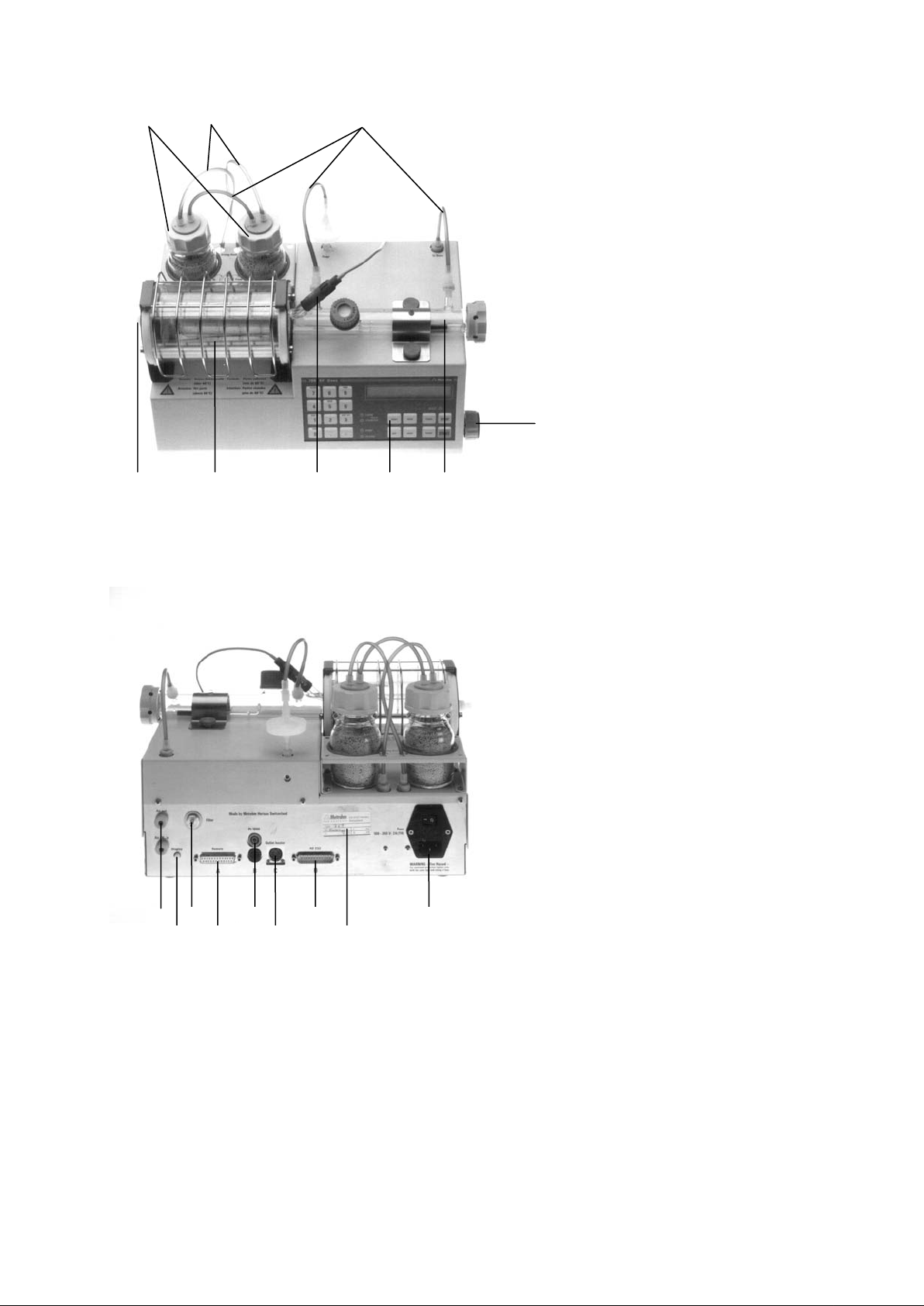
Parte anterior
1 Botella de secado
llena de cribas moleculares. Para secar el gas portant e.
2 Conexiones del tubo
con tubo 6.1805.180.
3 Conexiones del tubo
con tubo 6.1805.080.
4 Válvula de ajuste para el flujo de gas
5 Tubo insertado del horno
contiene navecilla de muestras con vara de conducción.
6 Panel de servicio
con pantalla, teclado y pilotos de estado.
7 Termosonda
para medir la temperatura de la muestr a.
8 Tubo de calentamiento
con paredes laterales blindadas y rejilla protectora.
9 Tubo de salida
conduce al recipiente de titración. Tubo 6.1805.070 o t ubo de
salida calentable 6.1830.000 (opcional).
2 768 Horno KF
Page 6

1.1 Vista general
Parte posterior
10 Conexión del tubo
con tubo 6.1805.040.
11 Ajustes del contraste para la pantalla
12 Filtro del aire
13 Conexión para titradores
14 Conexión para termosondas
conecte el enchufe gris del cable a la ficha roja del horno
15 Conexión para la calefacción de salida
16 Interface RS232
para la conexión de una impresora u ordenador
17 Placa indicadora de tipo
con número de fabricación, serie e instrum ento.
Indicación del voltaje ajustado en la red, la frecuencia de la red
y la energía absorbida. Antes de la primera conexión
compruebe si el voltaje ajustado coincide con el de su red
eléctrica. Si éste no fuera el caso, desconecte el cable de la
red y cambie el voltaje, vea página 43.
18 Equipo de alimentación
con interruptor y conexión a la red.
En el caso de redes en las que haya un voltaje con fuertes
interferencias HF, hay que equipar el horno KF con un filtro
adicional de la red, por ejemplo, el modelo de Metrohm 615.
768 Horno KF 3
Page 7
1.1 Modo de funcionamiento
To Oven
From Oven
To Oven
Purge
Air out
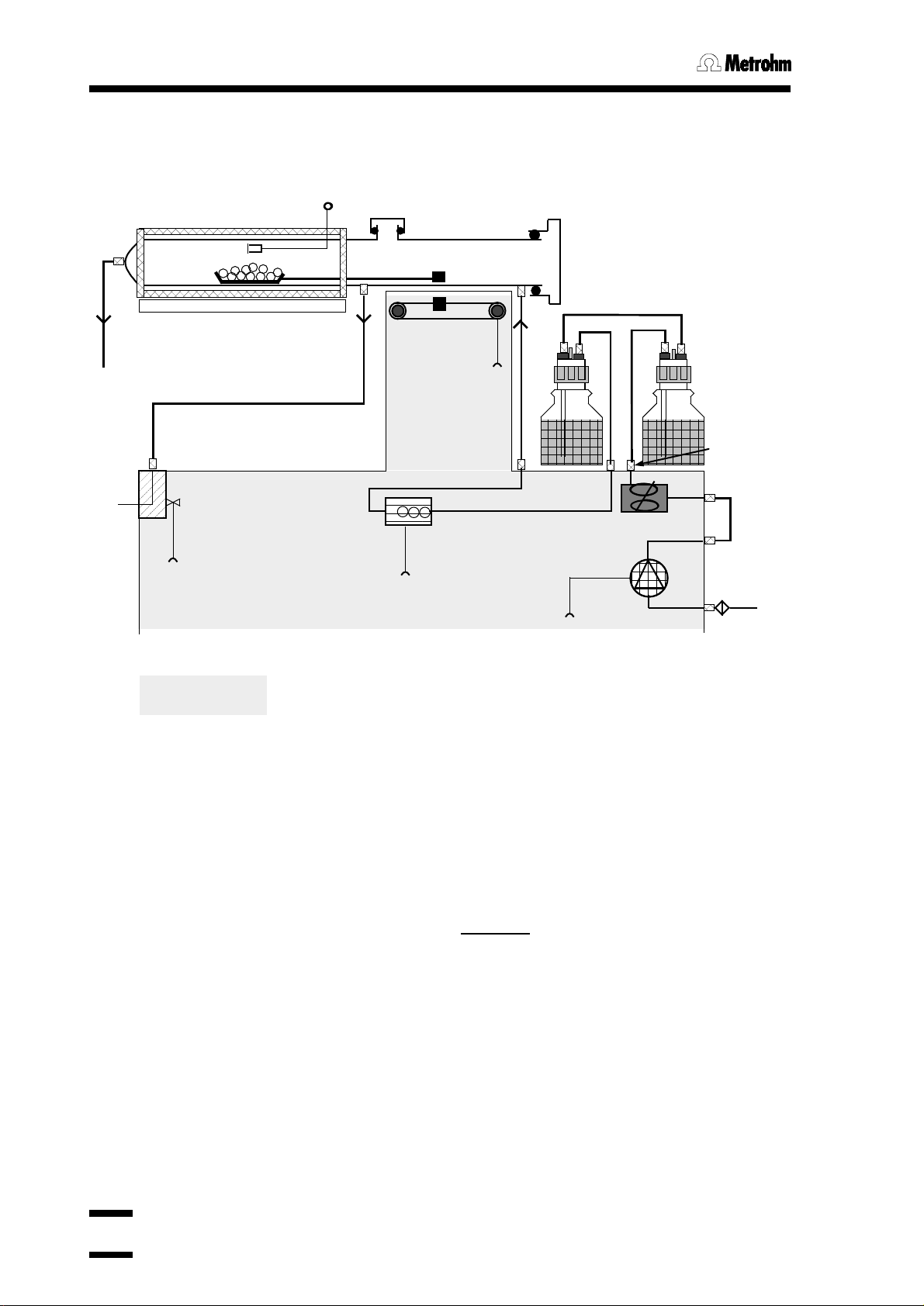
1.1 Modo de funci ona m iento
Esquema de funcionamiento:
temp.de muestra
navecilla
vidrio de calefacción
válvula en
"TRANSFER"
al recipiente de titración
válvula en
"PURGE"
imán
botellas de secado con
cribas moleculares
mueve la
navecilla
Air/N2 in
válvula
interior del Horno
medición del
flujo de gas
bomba de aire
ajuste del
flujo de gas
filtro de aire
Flujo de gas:
Si se utiliza aire como gas portante, se trabaja c on la bomba de air e incor por ada en el
horno. La bomba aspira el aire a través del filtro a tal efecto.
Si se utiliza otro tipo de gas como gas portante, s e introduce éste por el manguito "Air/N2
in".
El flujo de gas se ajusta con la válvula situada en la parte lateral del horno y es
conducido por medio de la botella de secado. La medición
del flujo de gas se realiza
inmediatamente antes de la entrada en el tubo insertado.
Si la válvula está en "PURGE", la corriente de gas fluye por la abertura "Purge". De este
modo se conduce sólo por la parte fría y anterior del tubo insertado.
Si la válvula está en "TRANSFER", el gas fluye por todo el tubo insertado, es decir,
también por la zona caliente del horno. La salida del gas se origina al final del tubo
insertado donde el gas es conducido a la célula de titración KF y se titra la humedad de
la muestra.
4 768 Horno KF
Page 8
2.1 Manejo de la navecilla de muestras
2. Condiciones de trabajo
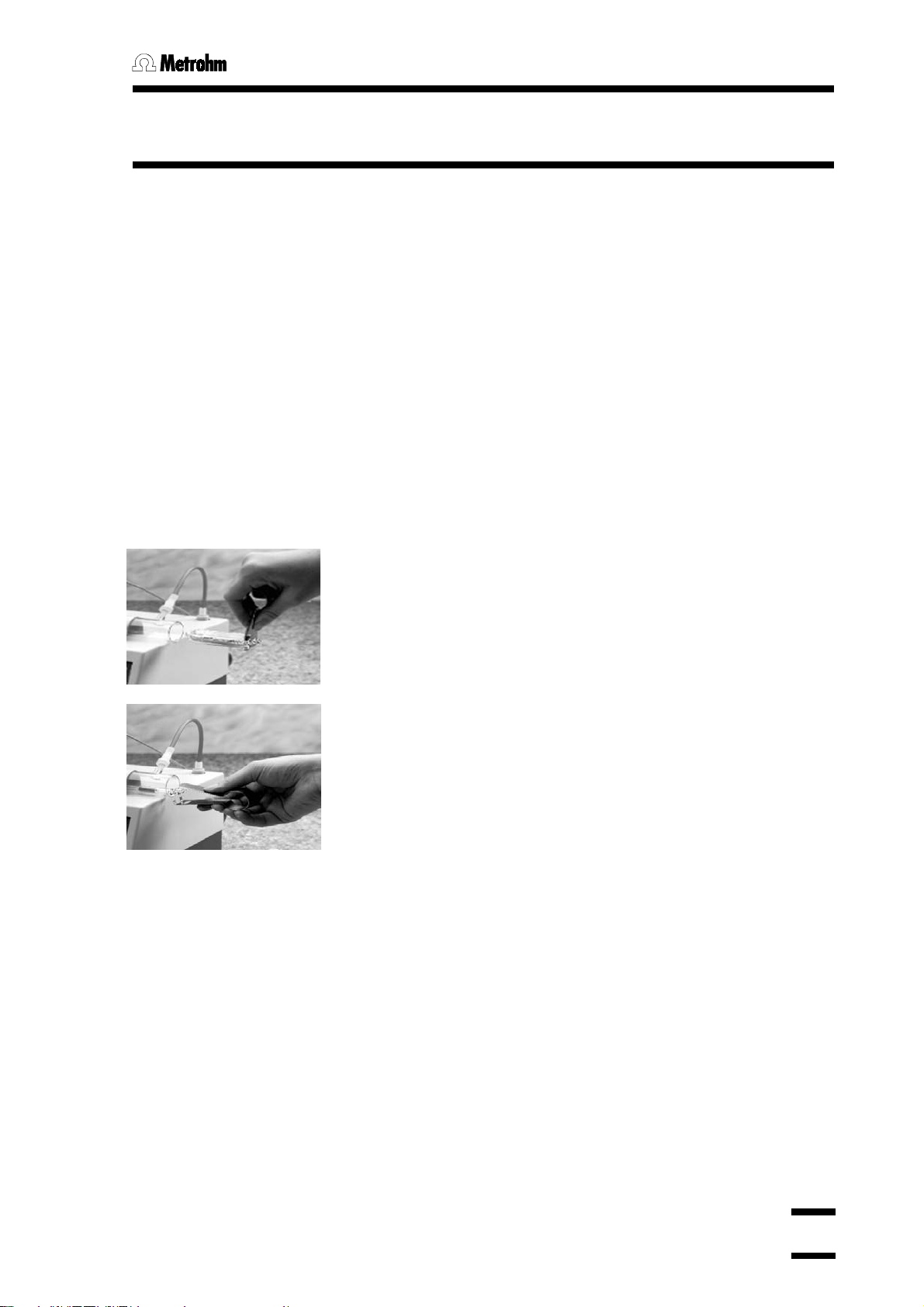
2.1 Manejo de la navecilla de muestras
La navecilla de muestras y la vara de conducción se han de
utilizar siempre con la abrazadera de sujeción 6.2056.000
para poder, así, evitar que el resultado de la medición sea
erróneo debido a la humedad del piel adherida al vidrio.
Tanto la navecilla de muestras como la vara de conducción
han de secarse bien después de su limpieza (secador, horno
de secado) y almacenarse en un desecador.
La limpieza de la navecilla de muestras no es necesaria si se
utilizan las inserciones de aluminio (número de pedido
6.2623.000) (especialmente aconsejable si las muestr as se
funden o descomponen).
Introducción de la navecilla de muest r as en el hor no:
Sujete la navecilla con la abrazadera de modo que el anillo
de la navecilla ajuste en la abertura de la abrazadera.
Coloque la navecilla en el tubo insertado. El anillo debe
sobresalir aún.
Sujete la vara de conducción con la abrazadera. Los dos
dientes de la abrazadera han de quedarse por debajo.
Enganche la vara de conducción al anillo de la navecilla y
hágalo entrar en el tubo insertado.
La navecilla también se puede sujetar con la vara de
conducción e introducir, como unidad "Navecilla y vara de
conducción", en el horno.
Cierre el tubo insertado con la tapa.
Ponga en marcha con <START>.
Para sacar la navecilla de muestras del horno:
Abra la tapa del tubo insertado.
Sujete la vara de conducción con la abrazadera y sáquela
hasta que el final de la navecilla de muestras desde el tubo
insertado se pueda sujetar bien con la abrazadera.
Desenganche la vara de conducción del anillo de la navecilla
y deposítelo, por ejemplo, detrás del horno. Déjelo de tal
forma que la agarradera de la vara de conducción
sobresalga por encima del canto superior del horno y se
pueda sujetar fácilmente con la abrazadera.
Sujete la navecilla con la abrazadera y sáquela.
La navecilla y la vara de conducción también se pueden
sacar juntas del horno.
Cierre de nuevo el tubo insertado con la tapa.
768 Horno KF 5
Page 9
2.2 Desarrollo automático de una determinación
READY
READY
2.2 Desarrollo automático de una determinación
La automatización de la secuencia facilita la labor cuando hay un Titrador KF conectado.
Una vez comenzada la secuencia se efectuarán en el horno todos los pasos necesarios
para la determinación.
Una vez conectado, el horno se calienta a la
temperatura nominal (si en <CONFIG> est á ajustado a
"preparación auto: sí"). Si la temperatur a nom inal aún no
START
tiempo de purga 13 s
VALVE
TRANSFER
tiempo de acond. 5 s
VALVE
PURGE
ó
VALVE
TRANSFER
READY
se ha alcanzado, "READY" aparece intermitente.
Si se alcanza la temperatura nominal (en la gama
preseleccionada), se ilumina "READY"
permanentemente.
Ajuste el flujo de gas que desee (por ej.: 100 mL/min).
Efectúe el ajuste con el horno en caliente.
Pase la navecilla de muestras y la vara de conducción a
la parte fría del tubo insertado.
Comience la secuencia en el horno KF con la tecla
<START>.
Si se ha introducido un tiempo de purga, se esperará a
que éste haya transcurrido.
Si la válvula está en "PURGE", cambie a "TRANSFER",
es decir, el flujo de gas se conduce ahora al recipiente
de titración.
Si se ha introducido un tiempo de acondicionamiento, se
esperará a que éste haya transcurrido.
Se comprueba el Titrador conectado, si el recipiente de
titración está acondicionado (si <CONFIG> "s t ar t si
acond.ok: sí" está conectado), ent onces se desencadena automáticamente el Titrador y la navecilla de
muestras se desplaza a la parte caliente del horno. La
muestra se calienta, el agua de la muestra s e conduce
junto con el gas portante en el recipiente de tit r ac ión y
allí se titra.
Cuando la titración se acaba y con "ajustar válvula: sí",
la válvula se ajusta automáticamente a "PURGE"
(lavado) y la navecilla de muestras sale de la zona
caliente. Con "ajustar válvula: no" la válvula se deja a
"TRANSFER".
Si la temperatura nominal está en orden, se ilumina
"READY" y el horno está preparado para la siguiente
determinación.
6 768 Horno KF
Page 10
2.3 Ajustes en el Horno KF
7
8
9
4
5
6
1
2
3
0
.
–
QUIT
ENTER
PARAM
START
SELECT
CLEAR
CONFIG
STOP
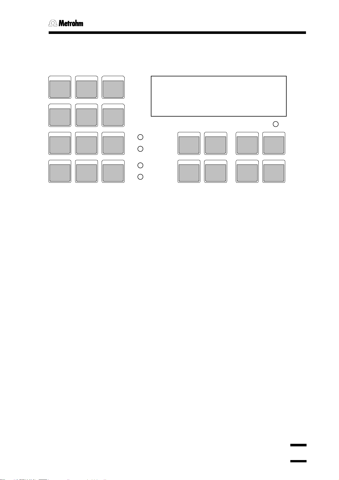
2.3 Ajustes en el Horno KF
2.3.1 Teclado
HEATER
VALVE
PUMP
PUMP
BOAT IN
PRINT
BOAT OUT
READY
PURGE
VALVE
TRANSFER
PUMP
HEATER
Teclas para las funciones manuales indivi dual es:
<HEATER> Conexión/desconexión de la calefacción. "HEATER" se
ilumina o aparece intermitente si la calefacción está
conectada. (El piloto se ilumina constantemente si se
calienta al máximo; aparece intermitente si funciona a un
nivel más reducido).
Nota: Si se desconecta la calefacción y se deja la válvula a
"TRANSFER" se puede aspirar solución del recipiente de
titración.
<PUMP> Conexión/desconexión de la bomba. "PUMP" se ilumina si la
bomba está conectada.
<VALVE> Conmutación de la válvula. "VALVE, PURGE" y "VALVE,
TRANSFER" muestran la posición de la válvula.
Por motivos de seguridad la válvula pasa a "PURGE" con el
aparato desconectado (aspiración de la solución del
recipiente de titración).
<BOAT IN> La navecilla de muestras pasa a la par t e c aliente del horno y
continúa hasta que se pulse de nuevo la tecla o hasta llegar
al tope interior.
<BOAT OUT> La navecilla sale de la parte caliente del horno y continúa
hasta que se vuelva a pulsar la tecla o hasta llegar al tope
exterior.
<PRINT> Se produce la impresión del informe.
Secuencia de las teclas:
<PRINT><SELECT> < ENTER>; pulse <SELECT> t antas
veces como sea necesario hasta que aparezca en la
pantalla el informe deseado
o
<PRINT><T e c la X><ENTER>; T e c la X = PARAM o
CONFIG
768 Horno KF 7
Page 11

2.3 Ajustes en el Horno KF
Teclas de control de entradas y de la secuencia:
<SELECT> Sirve para elegir las diferentes entradas. El sig no " :"
después del texto del diálogo indica que se utiliza
<SELECT> para la selección de las entradas.
Con <SELECT> se puede también elegir la ocupación de la
segunda línea de la pantalla: Conmutación de la indicación
del flujo de gas a mensajes, a la indicación de la
temperatura del horno y al flujo de gas nuevament e.
<CLEAR> - Borra los valores de entrada
- Ajusta los valores especiales, por ej.: "no"
<QUIT> - Salida de las consultas
- Parada de los tiempos de espera
- Parada de la impresión
- Salida de los mensajes de errores
<ENTER> - Recepción de valores de entrada
- Cierre de las secuencias de órdenes
Teclas con consultas rotatorias:
Pulsar repetidamente estas teclas conlleva al siguiente
(grupo de) consulta.
<CONFIG> Datos de la configuración, vea pág. 9.
Las consultas están distribuidas en grupos. Los t ítulos de
los grupos de preguntas están señalizados con ">" . Con
<ENTER> se entra en el grupo de consultas.
<PARAM> Parámetros para la secuencia automática, vea pág.11.
Teclas para la secuencia automática:
<STOP> Detiene la secuencia automática.
<START> Comienza la secuencia automática. El comienzo es sólo
posible, si "READY" está permanentemente encendido, es
decir, la temperatura nominal está en la gam a
preseleccionada por "límite temp.start".
8 768 Horno KF
Page 12

2.3 Ajustes en el Horno KF
Grupo de consultas: Ajustes generales del horno
Las consultas están dispuestas en grupos. El título de
2.3.2 Tecla <CONFIG>
CONFIG
dichos grupos está señalizado con ">". Para entrar en los
grupos de preguntas utilice <ENTER>.
>ajustes del horno
preparación auto: no
ajustar válvula: sí
start si acond.ok: no
límite temp.start 5 °C
corrección temp. 0 °C
transmisión a: IBM
impresión no
Preparación automática después de la conexión (sí, no)
"sí" significa: Calentamiento automático a la t em per atura
de la muestra.
Ajuste automáticamente la válvula (sí, no)
"sí" significa : Al final del desarrollo la válvula está ajustada
a "PURGE". Con "no", la válvula se deja a "TRANSFER".
Sólo es posible comenzar si el instrumento de titración
conectado está acondicionado (sí, no)
"sí" significa: La navecilla de muestras pasará a la parte
caliente del horno cuando el instrumento de titración
conectado esté acondicionado.
Si no hay ningún instrumento de titración conectado hay
que ajustarlo a "no".
Sólo es posible comenzar si la temperatura está en la
gama preseleccionada con respecto a la temperatur a
nominal (1...100 °C)
Corrección de la temperatura (0...
Corrección de la temperatura de muestra, vea página 55.
Selección del tipo de impresora/juego de caracteres
(Epson, Seiko, Citizen, HP, IBM)
"Epson" para modo Epson
"Seiko" por ej.: para DPU-414
"Citizen" por ej.: para iDP 562 RS
"HP" para modo HP
"IBM" para todas las impresoras con tablas de jueg o de
caracteres IBM 437, así como para la transmisión de
datos a un ordenador o sistema de datos.
Impresión al final del desarrollo automático (sí, no)
Ejemplo de impresión:
'fr
768 KF Oven 0D1/ 108 768. 0010
n. de muest ra 1
t i empo de pur ga 10 s
t i empo de acond. 5 s
t i empo de cal . 587 s
t emp. muest ra 150 º C Temp. nominal
t emp. mí ni ma 147 °C durante el calent.
t emp. máxi ma 150 ºC durante el calent.
t i po de gas: ai r e
f l uj o de gas 87 mL/ mi n flujo medio
=============
±
99.9 °C)
768 Horno KF 9
Page 13

2.3 Ajustes en el Horno KF
Grupo de consultas: Ajustes varios
>ajustes varios
diálogo: english
n.de muestra 0
comienzo auto no
t(espera) 0 s
aviso acústico 1
dirección
programa 5.768.0010
>ajustes para RS232
baud rate: 9600
data bit: 8
stop bit: 1
paridad: ninguna
handshake: HWs
control RS: sí
Selección de la lengua del diálogo (english, deutsch,
francais, español)
Número correlativo de la muestra (0.. .9999)
El número de la muestra se ajusta a 0 en la conexión.
Comienzos automáticos internos (1...9999, no)
Número de los comienzos automáticos.
Tiempo de espera (0...9999 s)
Tiempo de espera después del comienzo y antes de que
empiece el desarrollo automático. el tiempo de espera se
puede interrumpir con <QUIT>.
Aviso acústico (1...9, no)
Número de avisos acústicos cuando el aparato está
preparado.
Designación del instrumento para el reconocimiento
individual en la agrupación de aparatos (hasta 8
caracteres ASCII)
Indicación de la versión del programa
Grupo de consultas: Ajustes RS232
Baud Rate (300, 600, 1200, 2400, 4800, 9600)
Data Bit (7, 8)
Stop Bit (1, 2)
Paridad (par, impar, ninguna)
Handshake (HWs, HWc, SWlí nea, SWcar, ninguno)
vea también páginas 31ff.
Control vía interfase RS232 (no, sí)
"no" significa: La recepción de órdenes y datos por m edio
del interfase RS232 está cerrada. La emisión
de datos es
posible.
10 768 Horno KF
Page 14

2.3 Ajustes en el Horno KF
Temperatura de la muestra (50.. . 300 ° C)
Contiene los parámetros para el desarrollo automático.
el desarrollo automático.
2.3.3 Tecla <PARAM>
PARAM
temperatura 50 °C
un.flujo gas: mL/min
flujo gas min. 5 mL/min
tipo de gas: aire
tiempo de purga 0 s
*live
tiempo de acond. 0 s
*live
*live significa: Este parámetro se puede editar dur ante
Temperatura a la que hay que calentar la m uest ra.
Unidad para la indicación del flujo de gas (mL/min, L/h)
Todas las indicaciones y entradas para el flujo de gas se
ajustan según la unidad elegida.
Flujo mínimo de gas (0...999 mL/h o 0...59.9 L/h)
El desarrollo automático se puede efectuar s ólo cuando
se haya alcanzado el flujo mínimo de gas.
Selección del tipo de gas portante (aire, N2, otro) o
selección del gas para la determinación de humedad en el
gas.
Si se elige "otro", hay que introducir adicionalmente el
factor para la medición del flujo de gas. Como punto de
referencia para el factor puede observar los siguientes
valores
Ar 1.456 Aire 1.000
CH4 0.717 N2 0.999
CO2 0.738 N2O 0.666
Gas natural 0.681 O2 0.992
He 1.456 Propano 0.357
Tiempo de purga (0...99 999 s)
Tiempo de espera antes del calentamiento, es decir , antes
de que la navecilla pase al horno. La válvula permanece
en "PURGE".
El tiempo de espera se puede interrumpir con <QUIT>.
El tiempo de purga sólo se debe aplicar cuando la
muestra fría cede con dificultad la humedad.
Tiempo de acondicionamiento (0...99 999 s)
Tiempo de espera antes del calentamiento, es decir, antes
de que la navecilla pase al horno. La válvula cambia a
"TRANSFER".
El tiempo de espera se puede interrumpir con <QUIT>.
El tiempo de acondicionamiento sólo se debe aplicar
cuando la muestra fría cede con dificultad la humedad.
768 Horno KF 11
Page 15

+conecte el
2.3.2 Ajustes especiales
Desconecte el Horno. Pulse la tecla <CONFIG>, queda
CONFIG
Horno
>bloquear
<configuration> no
<parameters> no
<heater> no
<pump> no
<valve> no
<boat> no
>parámetros regulador T
factor cal.inicial 100 %
fact.cal.adicional 100 %
pulsando la tecla y conecta el horno.
Bloqueo de teclas
Tecla <CONFIG> (sí, no)
Tecla <PARAM> (sí, no)
Tecla <HEATER> (sí, no)
Tecla <PUMP> (sí, no)
Tecla <VALVE> (sí, no)
Tecla <BOAT IN> y <BOAT OUT> (sí, no)
Factores para la regulación de la temperatura del
Horno
La regulación de la temperatura está optima, es decir que
normalmente se puede quedar los dos fac t or es a 100 %.
Factor de calefacción inicial (0...200 %)
Calefacción después de introducir una muestra en el
Horno. Ponga un factor peq ueño cuando la t em per atura
se baja y se aumenta demasiado después.
Factor de calefacción adicional (0...200 %)
Después de la calefacción inicial empieza le regulación de
la temperatura. Ponga un f act or elevado cuando no se
alcanza la temperatura de forma rápida. En est e c aso se
puede también aumentar el factor cal. inicial.
12 768 Horno KF
Page 16

2.4 Instruc ciones pr ác t icas
2.4 Instrucciones prácticas
Introducción de muestras por la abertura superior del
tubo insertado
Si se van a calentar varias muestras consecutivamente en la
misma navecilla, se puede realizar de este modo.
Introduzca las muestras en la navecilla con una jeringa o
abra la tapa roscada.
Selección del gas portante
Se debería elegir N2 como gas portante siempre que la
muestra caliente sea sensible al aire o al oxígeno y ceda
sustancias oxidables.
Ajuste de temperatura
La temperatura hay que ajustarla a la mayor altur a que permita
la muestra (alta temperatura = c or t o tiempo de análisis): La
muestra puede desprender agua, pero no s ust anc ias
oxidables.
Tiempo de extracción
Hay que ajustar un tiempo de extracción de 2 minutos,
aproximadamente, en el Titrador conectado, con el fin de evitar
que la titración se detenga antes de que la muestra desprenda
el agua.
Acondicionamiento del sistema
Para acondicionar el sistema total antes del comienzo (sin
navecilla de muestras y sin muestras), se puede ajustar la
válvula del horno KF a "TRANSFER".
Literatura
- Hydranal ® Praktikum, Riedel-deHaën, 1987 (en inglés)
- G. Wieland, Karl Fischer Titration, GIT Verlag, Darmstadt,
1985 (en inglés o francés)
- Los siguientes boletines de aplicación de Metrohm (se
pueden encargar de forma g ratuita, en inglés o francés):
No. 109 Karl Fischer water determinations with the KF Ofen
Nr. 145 Determination of low water contents in plastics
Nr. 217 KF water determinations in pharmaceutics
768 Horno KF 13
Page 17

Page 18

3.1 General rules
15
3. Operation via RS232 interface
3.1 General rules
The 768 KF Oven has an extensive remote control facility that allows full control via the
RS232 interface, i.e. the instr um ent c an r eceive data from an external controller or it can
send data to an external controller. CR and LF are used as terminators f or t he data transfer.
The 768 KF Oven sends 2xCR and LF as termination of a data block
between a data line
commands with CR and LF. If the controller sends m or e than one command per line, the
character ';' is used as separat or bet ween the com m ands.
The commands are grouped logically and are simple to under stand. Thus, e.g. for the
selection of the dialog language the c om m and
must be sent, but only the boldface characters need be inputted, thus
The data groups of t his or der ar e:
Config Entries for the configuration
Aux Auxiliaries, various subjects
Language Dialog language
The commands have a hierarchial structure (tree structure). The quantities that appear in
this tree are called objects in what follows. The dialog languag e is an obj ect that is called up
with the command
If one is at the desired location in the tr ee, t he value of the appropriate object can be
queried:
$Q triggers the out put of the value from the 768 KF Oven. Entries that ar e int r oduc ed with
the character dollar ($) trig ger something. They are thus called triggers in what follows.
Values of objects can not only be requested, however, they can also be modified. Values are
always entered in quotation marks (”), e. g.
which has CR and LF as terminator. The cont r oller terminates its
&Config.Aux.Language ”english”
&C.A.L "english" .
&Config.Aux.Language ”english”
&Config.Aux.Language ”english” $Q Q for Quer y
&Config.Aux.Language ”english”
, to differentiat e
768 KF Oven
Page 19

3.1 General rules3.1 General rules
Language Prog
Aux
Config
&
Root
RSSet
Mode
3rd node
2nd node
1st node
0st node
The root of the tr ee is desig nated with &.
For the call up of an object the nodes (levels)
of the tree are marked with a point (.).
The call up of the objects requires as many
object in the series is recognized.
Call up of dialog language:
Upper or lowercase letters can be used.
&C.A.L
or &c.a.l
An object can be assigned a value. Each value
to enter leading zeros.
Input of dialog language:
If a new object is not called up, the old object
Input of a diff er ent dialog language:
"deutsch"
New objects can also be addressed relative to
From the root to node 'Aux':
.P
backwards require n + 1 preceding points.
Jump from node 'Prog' to node 'Aux' and
..L
If a jump is to be made back to the root, a
Jump from node 'Language' via root to the
&M
3.1.1 Call up of objects
All objects are grouped hierarchically. They have a tree structure. A section of this tree is shown
below:
Rules Example
letters as necessary to ensure unequivocal the
object. If the call is not unequivocal, the first
is marked at the beginning and end with
quotation marks (" ) . A value can contain up to
24 characters. Numeric values can include up
to 6 digits, a negative sign and a decimal point.
Numbers with more than 6 digits will not be
accepted; more than 4 decimal places are
rounded off. With numbers <1, it is neces sar y
remains current.
old objects: A preceding point moves one
node forwards in the t r ee.
More than one preceding point moves one
node backwards in the tr ee. n nodes
&Config.Aux.Language
or &C.A.L
&C.A.L"english"
Correct entry of a number:
"0.1"
Incorrect entry:
"1,5" or "+3" or ".1"
&C.A
From node 'Aux' to 'Prog':
selection of a new object at this node:
preceeding & is entered.
768 KF Oven
16
node 'Mode':
Page 20

3.1 General rules
17
3.1.2 Triggers
Triggers initiate an action at t he KF O ven, e. g. starting of a mode or s ending of data.
Triggers are mar ked with the introducer: $
The following triggers ar e poss ible:
$G Go: Starts operations, e.g. start of the automatic determination or set ting
of the RS232 interface parameters
$S Stop: Stops operations
$Q Query: Used for inquiry of all inform at ion from the current node in the tree
upwards up to and including the values
$Q.P Path: Used for inquiry of the path from t he root of the tree up to the cur r ent
node
$Q.H Highest index: Used for inquiry of the number of s on nodes of the current node
$Q.N”i” Name: Used for inquiry of the name of the son node with index i, i = 1...n
$D Detailed I nfo: Used for inquiry of the detailed status
$U qUit: Used to abort the data flow of the 768 KF O ven, e. g. after $Q
The triggers $ G and $S are linked to obj ects, see overview table, pages 20ff.
The other trigger s, however, can be used at any time and at all locations on the object tree.
Examples:
Inquiry of baud rate: &Config.RSSet.Baud $Q
Inquiry of all values of the node RSSet: &Config.RSSet $Q
Inquiry of the path of node RSSet: &Config.RSSet $Q.P
Starting a mode: &Mode $G
Inquiry of the detailed status: $D
768 KF Oven
Page 21

3.1 General rules3.1 General rules
3.1.3 Status and error messages
Detailed status conditions
Status conditions of the global $G :
$G.Mode .Inac Waiting during start delay
.PurgeTime Waiting dur ing purge time
.CondTime Waiting during cond.time
.HeatSmpl Heating the sample
.Terminate Carrying out the terminating st eps
$G.Assembly .Prep.Wait Heating the oven to the set temperatur e
.Boat The sample boat has been manually moved
Status conditions of the global $R:
$R.Mode .Ready Inactive: Ready to start an automatic determination
$R.Assembly.Ready An Assembly step has been carried out. Ready to carry out
another Assembly step (&Mode $G will trigger error message
E31).
Status conditions of the global $S:
The instrument gives the status from which it has been stopped. The detailed status information is
therefore identical as for t he global status $G.
Error messages
RS receive errors:
E36 Parity error
Exit: <QUIT> and set parity at both devices the sam e.
E37 Stop Bit
Exit: <QUIT> and set stop bit at both devices the same.
E38 Overrun error. At least 1 character could not be r ead.
Exit: <QUIT>.
E39 The internal receive buffer is full (> 82 c har acters).
Exit: <QUIT>.
768 KF Oven
18
Page 22

3.1 General rules
19
RS send errors:
E40 DSR=OFF. No proper handshake for more than 1 s.
Exit: <QUIT>. Is the rec eiver switched on and ready to receive?
E41 DCD=ON. No proper handshake for more t han 1 s.
Exit: <QUIT>. Is the rec eiver switched on and ready to receive?
E42 CTS=OFF. No proper handshake for m or e t han 1 s .
Exit: <QUIT>. Is the rec eiver switched on and ready to receive?
E43 The transmission has been interrupted with XOFF for at least 3
s.
Exit: Send XON or <QUIT>.
E44 The RS parameters are no longer the same for both devices.
Reset.
E45 The receive buffer contains an incomplete com m and ( LF
missing). Sending from t he instrument is therefore block ed.
Exit: Send LF or <QUIT>.
Device-specific errors:
E26 Manual stop.
Exit: The error message disappears on t he next st art.
E135 Check temperature sensor of sample temperature.
Exit: Rectify fault.
E154 Sample temperature not OK.
Exit: The error message disappears when the fault is rectified
or &M $S.
E163 Gas flow too low.
Exit: T he er r or m es sage disappears when the fault is rectified
or &M $S.
E164 The attached titrator is not condit ioned.
Exit: The error message disappears when the fault is rectified
or &M $S.
E165 The oven temperature is higher than 360 °C.
Exit: The error message disappears when the fault is rectified.
E168 The temperature sensor for the oven temperature is not OK.
Exit: Rectify fault.
E169 The gas flow sensor is not OK (flow >500 mL/min).
Exit: Rectify fault. Continuation is possible only when the
minimum gas flow is set to 0 mL/min.
768 KF Oven
Page 23

3.2 Remote control commands3.2 Remot e c ont r ol com m ands
3.2 Remote control commands
3.2.1 Overview
│& Root
│ Mode Mode $G, $S 3.2.2.1
│ │ .Temp Sample temperature 50...300 3.2.2.2
│ │ .Gas Gas flow
│ │ │ .UnitFlow Unit for display mL/min, L/h 3.2.2.3
│ │ │ .MinFlow Minimum gas flow 0...999 3.2.2.3
│ │ │ .Type
│ │ │ │ .Select Selection of the gas type air, N2, ot her 3.2.2.4
│ │ │ │ .OtherFac Factor for "other" gas 0.001...9.999 3.2.2.4
│ │ .PurgeTime Pur ge time 0...99999 3.2.2.5
│ │ .CondTime Conditioning time 0...99999 3.2.2.5
│
│
│ Config Configuration
│ │ .OvenSet Oven settings
│ │ │ .AutoPrep Aut om atic preparation ON, OFF 3.2.2.6
│ │ │ .ValveControl Valve control ON, OFF 3.2.2.7
│ │ │ .StartCond Start allowed only if cond.ok ON, OFF 3.2.2.7
│ │ │ .TempLimit Starting temperature range 1...100 3.2.2.7
│ │ │ .TempCorr Cor r ec t ion of sample temperature 0...±99.9 3.2.2.7
│ │ │ .CharSet Selection of the character set Epson, Seik o,
│ │ │ Citizen, HP, IBM 3.2.2.8
│ │ │ .Report Report output at end ON, OFF 3.2.2.9
│ │
│ │ .Aux Setti ng of various auxi liary functions
│ │ │ .Language Selection of the dialog language english, deutsch,
│ │ │ francais,
│ │ │ espanol 3.2.2.10
│ │ │ .RunNo Current r un num ber 0...9999 3.2.2.11
│ │ │
│ │ .AutoStart I nternal automatic start 1...9999,OFF 3.2.2.12
│
│ │ │ .StartDelay Start delay 0...9999 3.2.2.12
│ │ │ .Beeper Beep 1...9, OFF 3.2.2.13
│ │ │ .DevName Device name 8 ASCIII 3.2.2.13
│ │ │ .Prog Program version read only 3.2.2.14
│ │
│ │ .RSSet Settings for RS232 $G 3.2.2.15
│ │ │ .Baud Baud rate (300...9600) 3.2.2.16
│ │ │ .DataBit Data bits 7, 8 3.2.2.16
│ │ │ .StopBit St op bit s 1, 2 3.2.2.16
│ │ │ .Parity Parity even, odd,
│ │ │ none 3.2.2.16
│ │ │ .Handsh Handshake HW s , HWf,
│ │ │ SWchar, SWline,
│ │ │ none 3.2.2.16
768 KF Oven
20
Page 24

3.2 Remote control commands
21
│& Root
│ Info Information
│ │ .Report Sending of formatted reports $G 3.2.2.17
│ │ │ .Select Selection of the report configuration,
│ │ │ parameters,
│ │ │ result 3.2.2.18
│ │ .Results Results of the determinati on
│ │ │ .PurgeTime Purge time r ead only 3.2.2.19
│ │ │ .CondTime Conditioning time read only 3.2.2.19
│ │ │ .SmplHeatTime Sample heating time read only 3.2.2.19
│ │ │ .LowTemp Lowest temp. during heating read only 3.2.2.19
│ │ │ .HighTemp Highest temp. during heating read only 3.2.2.19
│ │ │ .GasFlow Mean gas flow read only 3.2.2.19
│ │ │ .LowFlow Lowest f low during heating read only 3.2.2.19
│ │ │ .HighFlow Highest flow during heating read only 3.2.2.19
│ │
│ │ .ActualInfo Current information
│ │ │ .Inputs I/O lines, inputs
│ │ │ │ .Status Status of the lines read only 3.2.2.20
│ │ │ │ .Change Change in the st atus of the lines read only 3.2.2.20
│ │ │ │ .Clear Clears the change byte read only 3.2.2.20
│ │ │ .Outputs I/O lines, outputs
│ │ │ │ .Status Status of the lines read only 3.2.2.20
│ │ │ │ .Change Changing the status of the lines read only 3.2.2.20
│ │ │ │ .Clear Clears the change byte read only 3.2.2.20
│ │ │ .Meas Measured values
│ │ │ │ .CyclNo Cycle number read only 3.2.2.21
│ │ │ │ .SampleTemp Sample temperature read only 3.2.2.21
│ │ │ │ .OvenTemp Oven temperature read only 3.2.2.21
│ │ │ │ .GasFlow Gas flow read only 3.2.2.21
│ │ │ .Status Status of the assemblies
│ │ │ │ .BoatPos Position of the sample boat read only 3.2.2.22
│ │ │ │ .Valve Valve position read only 3.2.2.22
│ │ │ │ .Pump Pump read only 3.2.2.22
│ │ │ │ .Heating Heating power level read only 3.2.2.22
│ │ │ .Display Display
│ │ │ │ .L1 1st line 24 ASCII 3.2.2.23
│ │ │ │ .L2 2nd line 24 ASCII 3.2.2.23
│ │
│ │ .Assembly Assembly
│ │ │ .CycleTime Cycle tim e read only 3.2.2.24
│
│
│ Assembly Basic components of the assembly
│ │ .Prep Perform preparations $G, $S 3.2.2.25
│ │ .Heat Heating on $G 3.2.2.26
│ │ │ .Value Heating power level 0...50 3.2.2.26
│ │ .Valve Set valve position $G 3.2.2.27
│ │ │ .Pos Preselect position purg e, transfer 3.2.2.27
│ │ .Boat Move sample boat $G , $S 3.2.2.28
│ │ │ .Rate Moving rate 0.1...10 3.2.2.28
│ │ │ .Pos Go to posit ion 0...130.0 3.2.2.28
│ │ │ .SetPos Set s t op point s
│ │ │ │ .InPos Inner stop 0...130.0 3.2.2.28
│ │ │ │ .OutPos Outer stop 0...130.0v 3.2.2.28
│ │ .Pump Switch pump on/off $G, $S 3.2.2.29
│ │ .Outputs I/O lines, outputs
│ │ │ .SetLines Set lines $G 3.2.2.30
│ │ │ │ .L1 Line 1 active, inactive
│ │ │ │ : pulse, OFF 3.2.2.30
│ │ │ │ .L8 All lines as L1
│ │ │ .ResetLines Set all lines inactive $G 3.2.2.30
768 KF Oven
Page 25

3.2 Remote control commands3.2 Remot e c ont r ol com mands
│& Root
│ Setup Setting the operat i ng m ode
│ │ .IdReport Output report identification ON, OFF 3.2.2.31
│ │ .Keycode Key code of pressed keys ON, OFF 3.2.2.32
│ │ .Tree Def inition of response to $Q
│ │ │ .Short Send short path name ON, OFF 3.2.2.33
│ │ │ .ChangedOnly Only paths with changed values ON, OFF 3.2.2.33
│ │ .Trace Message when values change ON, OFF 3.2.2.34
│ │
│ │ .Lock Lock functions
│ │ │ .Keyboard Lock all keys ON, OFF 3.2.2.35
│ │ │ .Config Lock <CONFIG> key ON, OFF 3.2.2.35
│ │ │ .Parameter Lock <PARAM> key ON, OFF 3.2.2.35
│ │ │ .Heater Lock <HEATER> k ey ON, OFF 3.2.2.35
│ │ │ .Pump Lock <PUMP> key ON, OFF 3.2.2.35
│ │ │ .Valve Lock <VALVE> key ON, OFF 3.2.2.35
│ │ │ .Boat Lock <BOAT IN/OUT> keys ON, OFF 3.2.2.35
│ │ │ .Display Lock display operation of 768 ON, OFF 3.2.2.35
│ │
│ │ .TController Fact or s f or t em perature controller
│ │ │ .InitHeatFactor Inital heating factor 0...200 3.2.2.36
│ │ │ .AddHeatFactor Heating after initial phase 0...200 3.2.2.36
│ │
│ │ .SendMeas Automatic transmission of measur em ent dat a
│ │ │ .SendStatus On/off switching of transmission ON, OFF 3.2.2.37
│ │ │ .Interval Time interval for transmission 1...16200 3.2.2.37
│ │ │ .Meas Measured values for transmission
│ │ │ │ .CyclNo Cycle number ON, OFF 3.2.2.37
│ │ │ │ .SampleTemp Sample temperature ON, OFF 3.2.2.37
│ │ │ │ .OvenTemp Oven temperature ON, OFF 3.2.2.37
│ │ │ │ .GasFlow Gas flow ON, OFF 3.2.2.37
│ │
│ │ .AutoInfo Automatic message on changes
│ │ │ .Status On/off of all set messages ON, OFF 3.2.2.38
│ │ │ .P When power is switched on ON, OFF 3.2.2.38
│ │ │ .T Messages of aut om atic determination
│ │ │ │ .G Status becomes "Go" ON, OFF 3.2.2.38
│ │ │ │ .R Status becomes "Ready" ON, OFF 3.2.2.38
│ │ │ │ .S Status becomes "Stop" ON, OFF 3.2.2.38
│ │ │ │ .B Beginning of sample heating ON, OFF 3.2.2.38
│ │ │ │ .F Finish of sample heating ON, OFF 3.2.2.38
│ │ │ │ .E Err or message ON, OFF 3.2.2.38
│ │ │ .I Change of an I/O input ON, OFF 3.2.2.38
│ │ │ .O Change of an I/O output ON, OFF 3.2.2.38
│ │
│ │ .PowerOn Simulation "Power on" $G 3.2.2.39
│ │ .Initialise Set values to default $G 3.2.2.40
│ │ │ .Select Selection Mode,Config,All
│ │ │ Setup,Assembly 3.2.2.40
│ │ .RamInit Initialisation $G 3.2.2.41
│ │ .InstrNo Set instrument identification $G 3.2.2.42
│ │ │ .Value Enter inst r um ent identification 8 ASCII 3.2.2.42
│ │ .Save Store in EEPROM $G 3.2.2.43
768 KF Oven
22
Page 26

3.2 Remote control commands
23
3.2.2 Description of the remote c ont rol commands
3.2.2.1 Mode $G, $S
Start and stop ($G, $S) of the automatic determination.
3.2.2.2 Mode.Temp 50...300
Entry of the sample temperatur e in °C.
3.2.2.3 Mode.Gas.UnitFlow mL/min, L/h
Mode.Gas.MinFlow 0...5...999
.UnitFlow: Selection of the unit for display of the gas flow.
.MinFlow: Setting of t he m inimum gas flow in the unit selected above. If the flow is less
than the minimum gas flow, error E163 appear s ( gas flow too low).
3.2.2.4 Mode.Gas.Type.Select air, N2, other
Mode.Gas.Type.OtherFac 0.001...1...9999
.Select: Selection of the gas.
.Factor: If "other" has been selected above, setting of the factor f or m eas ur em ent of
the gas flow, factors see page 11.
3.2.2.5 Mode.Gas.PurgeTime 0...99999
Mode.Gas.CondTime 0...99999
.PurgeTime: Purge time with valve to "Purge". Entry in s.
.CondTime: Conditioning time with valve to "Transfer ". Entry in s.
3.2.2.6 Config.OvenSet.AutoPrep ON, OFF
ON means: Automatic heating and prepar at ion of the oven after switching on.
3.2.2.7 Config.OvenSet.ValveControl ON, OFF
Config.OvenSet.StartCond ON, OFF
Config.OvenSet.TempLimit 1...5...100
Config.OvenSet.TempCorr 0...±99.9
• ValveControl:
ON means automatic switching of the valve from PURGE t o TRANSFER at the end of the
determination.
• StartCond:
ON means: Insert sample boat during automatic determination only if the connected
device is conditioned (input line pin 12 of the socket "Remote" active).
• TempLimit:
Starting a determination is possible only if the current temperature is in the range of ±X
°C from the sample temper at ur e.
• TempCorr:
Correction of the sample temper at ure according to individual sample and Oven
requirements.
768 KF Oven
Page 27

3.2 Remote control commands3.2 Remot e c ont r ol com m ands
3.2.2.8 Config.OvenSet.CharSet Epson, Seiko, Citizen,
HP, IBM
Selection of the character set.
IBM means IBM character set according to character set table 437. Select "IBM" for work
with the computer.
3.2.2.9 Config.OvenSet.Report ON, OFF
ON means: Output of a r epor t at the end of the automatic determination.
3.2.2.10 Config.Aux.Language english, deut s ch, francais, español
Selection of the dialog language.
3.2.2.11 Config.Aux.RunNo 0...9999
Current run number.
Is set to 0 on power on and on initialisation. Counting starts again at 1 after 9999 has been
reached.
3.2.2.12 Config.Aux.AutoStart 1...9999, OFF
Config.Aux.StartDelay 0...9999
.AutoStart: Number of aut om atic, internal starts for automatic determinations.
.StartDelay: Start delay time in s. During this time, the data of t he pr ec eding determination
are retained.
3.2.2.13 Config.Aux.Beeper 1...9, OFF
Config.Aux.DevName up to 8 ASCII characters
Number of beeps if the Oven is ready and after the determinations.
Name of the device for interconnect ions with several devices. It is advisable to use only the
characters A...Z (ASCII No. 65...90), a...z (ASCII No. 97...122) and 0...9 (ASCII No. 48...57)
if the Setup.AutoInf o function (see 3.2.2.38) has been activated at t he s am e t im e.
3.2.2.14 Config.Aux.Prog read only
Output of the prog r am version.
In response to $Q, the KF Oven sends: "5. 768.0010".
3.2.2.15 Config.RSSet $G
$G sets all RS settings. Aft er setting the interface parameters, wait at least 2 s to allow the
components to equilibrate.
3.2.2.16 Config.RSSet.Baud 300, 600, 1200, 2400, 4800, 9600
Config.RSSet.DataBit 7, 8
Config.RSSet.StopBit 1, 2
Config.RSSet.Parity even, odd, none
Config.RSSet.Handsh HWs, HWf, SWchar, SWline, none
Setting of the RS interface parameters: Baud rate, data bit s, s t op bit s, parity and type of
handshake, see also page 31.
Setting of the values must be initiated imm ediat ely f ollowing the entr y with &Config . RSSet
$G, see 3.2.2.15.
768 KF Oven
24
Page 28

3.2 Remote control commands
25
3.2.2.17 Info.Report $G
Output of the selected repor t.
3.2.2.18 Info.Report.Select configuration, parameters, r es ult
Selection of the report.
configuration: Configur at ion r epor t . Not accessible when a determination is running.
parameters: Parameter report. Only "live" parameters when a determ inat ion is r unning .
result: Result report of the last completed determinat ion.
The report output must be t riggered with &Info.Report $G, s ee 3. 2.2.17.
Reports which are sent automatically by the KF Oven start with a space (ASCII 32) and '.
This is followed by the individual identification for each report. Report s which are req ues t ed
via RS232 ($G) have the same individual identification of the report block s, but are started
with ' only (no preceding space).
3.2.2.19 Info.Results.PurgeTime read only
Info.Results.CondTime read only
Info.Results.SampleHeatTime read only
Info.Results.LowTemp read only
Info.Results.HighTemp read only
Info.Results.GasFlow read only
Info.Results.LowFlow read only
Info.Results.HighFlow read only
Inquiry of the current r esult s .
.PurgeTime: Purge time.
.CondTime: Conditioning time.
.SampleHeatTime: Time during which the sample has been heated.
.LowTemp: Lowest temperature during the sample heating.
.HighTemp: Highest temperat ur e dur ing the sample heating.
.GasFlow: Mean gas flow during the sample heating.
.LowFlow: Lowest gas flow during the sample heating.
.HighFlow: Highest gas flow during the sample heating.
3.2.2.20 Info.ActualInfo.Inputs.Status read only
Info.ActualInfo.Inputs.Change read only
Info.ActualInfo.Inputs.Clear $G
Info.ActualInfo.Outputs.Statusread only
Info.ActualInfo.Outputs.Changeread only
Info.ActualInfo.Outputs.Clear $G
Status sends the current stat us of the I/O lines. Change sends information regarding
whether a change in the status of a line has taken place since it was last cleared, Clear
clears the byte of Change.
For the output, the byte is converted to binary, e.g.
|0|0|0|0|1|0|1|0|
Line No. |7|6|5|4|3|2|1|0| Output: 21 + 23 = "10"
1 means ON or change; 0 means OFF or no c hange.
The lines are assigned as follows (see also pages 53, 54):
Inputs: Outputs:
0 Start (Pin 21) 0 Ready (Pin 5)
1 Stop (Pin 9)
1 Start (Pin 18)
2 Terminate (Pin 22) 2 Stop (Pin 4)
3 Pin 10 3 HeatSmpl (Pin 17)
4 Pin 23 4 Terminat e ( Pin 3)
5 Pin 11 5 Error (Pin 16)
6 Pin 24 6 Pin 1
7 Cond.ok (Pin 12) 7 Pin 2
768 KF Oven
Page 29

3.2 Remote control commands3.2 Remot e c ont r ol com m ands
3.2.2.21 Info.ActualInfo.Meas.CyclNo read only
Info.ActualInfo.Meas.SampleTemp read only
Info.ActualInfo.Meas.OvenTempread only
Info.ActualInfo.Meas.GasFlowread only
Inquiry of the current values.
NV: Not Valid.
If the measured value is exceeded, OV (overrange) is sent .
A time frame can be generat ed from the cycle number and the cycle time (see 3.2.2. 24).
The cycle number is always zeroed on start and on termination of an automat ic
determination.
3.2.2.22 Info.ActualInfo.Status.BoatPosread only
Info.ActualInfo.Status.Valve read only
Info.ActualInfo.Status.Pump read only
Info.ActualInfo.Status.Heating read only
Status inquiry of the individual assemblies in the following form at (examples):
.BoatPos Position of the sample boat 23 mm
.Valve Position of t he valve "purge" or "t r ansfer"
.Pump Status of the pump "ON" or "OFF"
.Heating Heating level 20
3.2.2.23 Info.ActualInfo.Display.L1 up to 24 ASCII character s
Info.ActualInfo.Display.L2 up to 24 ASCII characters
1st and 2nd line of the display. The display can be written to.
The display is not operated by the KF oven if &Setup.Lock.Display is set to ON, s ee
3.2.2.35.
$Q sends the contents of the c or r es ponding display line.
3.2.2.24 Info.Assembly.CycleTime read only
Inquiry of the cycle time in s.
3.2.2.25 Assembly.Prep $G, $S
Switch heating to the sample temperature on/ off.
3.2.2.26 Assembly.Heat $G
Assembly.Heat.Value 0...50
Control heating. The set heating power level is started with &Assembly.Heat $G.
0 means switch off heating.
3.2.2.27 Assembly.Valve $G
Assembly.Valve.Pos purge, transfer
Set valve. The selected position is set with &Assembly.Valve $G.
3.2.2.28 Assembly.Boat $G, $S
Assembly.Boat.Rate 0.1...10
Ass
embly.Boat.Pos 0...130.0
Assembly.Boat.SetPos.InPos 0...130.0
Assembly.Boat.SetPos.OutPos0...130.0
The movements of the sample boat ar e init iated with &Assembly.Boat $G.
768 KF Oven
26
Page 30

3.2 Remote control commands
27
3 4 5 11 12 13 19 20 21 27 28 29 6
14
22
30 7 15
23
31
.Rate: Rate in mm/s
.Pos: Position m oved to with &Assembly.Boat $G, in mm. The inputted position is
moved to irrespective of the limits set in &Assembly.Boat. Set Pos.
.SetPos: Limits f or t he movement of the boat in automatic determ inat ions and for
manual operation.
.InPos: Inner stop in mm.
.OutPos: Outer stop in mm.
3.2.2.29 Assembly.Pump $G, $S
Switch pump on/off.
3.2.2.30 Assembly.Outputs.SetLines $G
Assembly.Outputs.SetLines.L1 active, inactive, pulse, OFF
up to .L8
Assembly.Outputs.ResetLines $G
Setting of the output lines of the "Remote" socket.
.SetLines: All lines are set with $G.
.SetLines.L1: Setting of line 1. "active" sets a st at ic s ig nal ( 0 V) , " inact ive" res et s t he signal
(+5 V) , "pulse" means a pulse of leng th of ca. 150 ms and with "OFF" the
corresponding line is not controlled.
Assignment of the lines, see 3.2.2.20.
up to .L8
.ResetLines: Lines L1...L8 are set to the inactive condition (+5 V).
3.2.2.31 Setup.IdReport ON, OFF
Switch output of the report identification on/off.
3.2.2.32 Setup.Keycode ON, OFF
With ON t he key code of a key pressed on the KF Oven is outputted. T he key code
comprises 2 ASCII characters see below. Space (ASCII 32) and # ar e sent as introducers.
Example : #11
3.2.2.33 Setup.Tree.Short ON, OFF
Setup.Tree.ChangedOnly ON, OFF
Definition of the response to an inq uiry with $Q.
.Short: With ON all path nam es ar e s ent , but only with the requisite number of
characters. Requisite number of characters means the path is unequivocally
characterised (characters pr inted in boldface in the instructions for use).
768 KF Oven
Page 31

3.2 Remote control commands3.2 Remot e c ont r ol com m ands
.ChangedOnly: Sends only those paths and their values which have once been edited. All
path names are sent in absolute terms, i.e. from the root.
3.2.2.34 Setup.Trace ON, OFF
The KF Oven reports when a value has been confirmed with <ENTER> at the KF Oven.
Space (ASCII 32) and & are sent as introducers.
Example: &Mode.Temp"100"
3.2.2.35 Setup.Lock.Keyboard ON, OFF
Setup.Lock.Config ON, OFF
Setup.Lock.Parameter ON, OFF
Setup.Lock.Heater ON, OFF
Setup.Lock.Pump ON, OFF
Setup.Lock.Valve ON, OFF
Setup.Lock.Boat ON, OFF
Setup.Lock.Display ON, OFF
ON means locking of the cor r es ponding function:
.Keyboard: Lock ing all keys at the KF Oven.
.Config: Locking the <CONFIG> key.
.Parameter: Locking the <PARAM> key.
.Heater: Locking the <HEATER> key.
.Pump: Locking the <PUMP> key.
.Valve: Locking the <VALVE> key.
.Boat: Locking the <BOAT I N> and < BO AT OUT> keys.
.Display: Locking the display, it is not operated by the device program of the KF Oven
and can be written to by the computer.
3.2.2.36 Setup.TController.InitHeatFactor 0...100...200
Setup.TController.AddHeatFactor 0...100...200
Factors for the temperature controller, see page 12.
3.2.2.37 Setup.SendMeas.SendStatus ON, OFF
Setup.SendMeas.Interval 1...4...16200
Setup.SendMeas.Meas.CyclNoON, OFF
Setup.SendMeas.Meas.SampleTemp ON, OFF
Setup.SendMeas.Meas.OvenTemp ON, OFF
Setup.SendMeas.Meas.GasFlowON, OFF
.SendStatus: ON means automatic transmission of measured values (see below) at the
inputted time interval.
.Interval: Time interval for the transmission of associated m easur ed values defined
below.
Selection of the values which are transmitted at the set t im e interval.
.CyclNo: Cycle number. T ogether with the cycle time (3.2.2.24), a time frame can be
generated. The other dat a ar e par t of the corresponding cycle number. The
cycle number is always zeroed at the start and termination of the aut om atic
determination.
.SampleTemp: Associated sam ple t em per ature.
.OvenTemp: Associated oven temper ature.
.GasFlow: Associated gas flow.
at of the transmitt ed values (examples):
Form
.CyclNo Cycle number 127
.SampleTemp Sample temperature in °C 150.0
.OvenTemp Oven temperature in °C 170.0
.GasFlow Gas flow in mL/min or L/h 100.5
768 KF Oven
28
Page 32

3.2 Remote control commands
29
NV: Not Valid.
If the measured value is exceeded, OV (overrange) is sent.
The associated values are sent on 1 line separated by a space (ASCII 32).
3.2.2.38 Setup.AutoInfo.Status ON, OFF
Setup.AutoInfo.P ON, OFF
Setup.AutoInfo.T.G ON, OFF
Setup.AutoInfo.T.R ON, OFF
Setup.AutoInfo.T.S ON, OFF
Setup.AutoInfo.T.B ON, OFF
Setup.AutoInfo.T.F ON, OFF
Setup.AutoInfo.T.E ON, OFF
Setup.AutoInfo.I ON, OFF
Setup.AutoInfo.O ON, OFF
Automatic message as soon as a change appear s.
.Status: Switches all set AutoI nfos on/off.
.P: PowerOn: Simulation PowerOn has been performed (3.2.2. 39) . No m ess age
on power on.
.T.G: Go: Automatic determination has been started.
.T.R: Ready: Automatic determination has been ended.
.T.S: Stop: An automatic determination has been stopped.
.T.B: Beg in: I n the automatic determination, the sample heat ing begins.
.T.F: Final: End of the sample heating in the automatic determinat ion.
.T.E: Err or: Message together with error number.
.I: Change in an input line of the "Remote" socket.
.O: Change in an output line of the "Remote" socket.
Each message is sent with space (ASCII 32) and ! as intr oducer s . The name of the device is
then sent (3.2.2.13). Special ASCII char ac t er s in t he device name are ignored. If no device
name has been entered, only ! is sent.
This is followed by information regarding t he node which initiated the m ess age. In the case
of errors, the err or num ber is sent.
Examples:
!Otto".T.G" Device Otto has been started.
!".T.E;E26" Device without a name has error E26.
3.2.2.39 Setup.PowerOn $G
Simulation of power on. The device has the same status as after power on: The boat is in
position 0 and the sample number on 0.
3.2.2.40 Setup.Initialise $G
Setup.Initialise.Select Mode, Config, All, Setup, Assembly
Sets default values for the f ollowing areas:
Mode: Branch Mode.
Config: Branch Config.
All: Values of the entire tree.
Setup: Branch Set up.
Assembly: Branch Assembly.
The action is initiated with &Setup.Initialise $G.
768 KF Oven
Page 33

3.2 Remote control commands3.2 Remot e c ont r ol com m ands
3.2.2.41 Setup.RamInit $G
Initialises the device as in the diagnostic test, see page 42: All parameters are set to the
default value and error messages are clear ed.
3.2.2.42 Setup.InstrNo $G
Setup.InstrNo.Value up to 8 ASCII
Device identification outputted in the report. The serial number and manufacturing num ber
are entered here in the factory as an uneq uivocal identif icat ion.
3.2.2.43 Setup.Save $G
All entries made via RS232 must be saved with &Setup.Save $G before the instrument is
switched off to avoid losses.
768 KF Oven
30
Page 34

3.3 Characteristics of the RS232 inter face
31
Start
7 or 8 data bits
Parit.bit
1 or 2 stop bit(s)
60 characters
TxD
RxD
Data output
Data input
Time of 4 characters
max. 22
XOFF XON
String is
LF
400
XOFF
characters
KF Oven
External device
processed
Time
us
3.3 Characteristics of the RS232 interface
3.3.1 Data transfer protocol
The KF Oven is configured as DTE (Data Terminal Equipment).
The RS232 interface has the f ollowing technical specifications:
Data interface in accordance with the RS232C standard, with select able par am et er s .
Max. line length: 80 characters + CR + LF
Control characters: CR (ASCII DEC 13)
LF (ASCII DEC 10)
XON (ASCII DEC 17)
XOFF (ASCII DEC 19)
Cable length: max. ca. 15 m
For interconnections of the 768 KF Oven with non-Metrohm units, only a shielded data cable
(e.g. METROHM D.104.0201) may be used. The cable shielding must be faultlessly earthed
at both units (pay attention to current loops; always use star-head ear thing). Only connectors
with adequate shielding may be used (e.g . METROHM K.210.0001 with K.210.9004).
3.3.2 Handshake
3.3.2.1 Softwar e handshake, SW Char
Handshake inputs at the Oven (CTS, DSR, DCD) are not chec ked.
Handshake outputs (DTR, RTS) ar e set by the Oven.
As soon as a LF is recognized, the Oven sends XOFF. It c an t hen r ec eive 6 extra charact ers
and store them.
However, the Oven also sends XOFF, if its input buffer contains 60 characters. After this, it
can receive maximum 22 extra characters (incl. LF).
If the transmission is interr upted for the time of 4 char acters after the Oven has sent XO FF,
the string received earlier is processed even if no LF has been sent.
Oven as receiver:
768 KF Oven
Page 35

3.3 Characteristics of the RS232 inter face3.3 Characteristics of t he RS232 inter face
max. 4
Data input
Data output
TxD
RxD
Data output disabled
XOFF
XON
Data output enabled
LF
characters
External deviceKF Oven
Time
LF
Input KF Oven disabled
TxD
RxD
Data output
Data input
XON
String is
Time
400 us
XOFF
External deviceKF Oven
LF
processed
KF Oven as sender:
3.3.2.2 Softwar e Handshake, SWline
Handshake inputs at the KF Oven (CTS, DSR, DCD) are not checked.
Handshake outputs (DTR, RTS) ar e set by the Oven.
The Oven is equipped with an input buffer that can ac com modate a string of up to 80
characters + CR LF. As soon as an LF is recognized, the Oven sends XOFF. Af ter this, it
can receive maximum 6 extra characters and store them . The string sent previously is now
processed by the Oven. Afterwards, the Oven sends X O N and is again ready to receive.
KF Oven as receiver:
768 KF Oven
32
Page 36

3.3 Characteristics of the RS232 inter face
33
Data input
Data output
TxD
RxD
Data output of Oven disabled
1 line
LF
XOFF
Inquiry
LF
XON
Data output of
Antwort
LF
External deviceKF Oven
Oven enabled
Time
LF
Time
KF Oven External device
RxD
DTR
RxD
DTR
Time
LF
RTS
CTS
TxD
RTS
CTS
TxD
KF Oven External device
KF Oven as sender:
The transmission of the O ven can be stopped by the external device with XOFF. After
receipt of XOFF, the Oven completes transmission of the line already started. If the data
output is disabled for more than 3 s by XOFF, E43 appears in the display.
3.3.2.3 Hardware handshake, HWs
KF Oven as receiver:
KF Oven as sender:
The data flow can be interrupted by deactivation of the CTS line.
768 KF Oven
Page 37

3.3 Characteristics of the RS232 inter face3.3 Characteristics of t he RS232 inter face
LF
Time
DTR
RxD
DTR
RxD
External device
KF Oven
LF
Time
RTS
DSR
DCD
CTS
TxD
RTS
DSR
DCD
CTS
TxD
External deviceKF Oven
3.3.2.4 Hardware handshake, HWf
All handshake inputs are checked at the Oven, handshake outputs are set.
KF Oven as receiver:
KF Oven as sender:
34
The data flow can be interrupted by deactivation of the CTS line.
768 KF Oven
Page 38

35
E 5
Clear to Send
external
RS 232C Interface
Received Data
E 3
E 4
Request to Send
E 20
Data Terminal Ready
Transmitted Data
E 2
E 6
Data Set Ready
E 7
Signal Ground
E 8
Data Carrier Detect
Transmitted data (TxD)
If no data are transmitted, the line is held in the "ON" condition. Data are
transmitted only when CTS and DSR are in the "ON" condition and DCD is
in the "OFF" condition.
Received data (RxD)
Data are received only when DCD is "ON".
Request to Send (RTS)
ON condition: Instrument is ready to send data.
Clear to Send (CTS)
ON condition: Remote station is ready to receive data.
Data Set Ready (DSR)
ON condition: The transmission line is connected.
Signal ground (GND)
Data Carrier Detect (DCD)
ON condition:The level of the received signal is within the tolerance range
(remote station is ready to send data).
Data Terminal Ready (DTR)
ON condition: Instrument is ready to receive data..
Contact arrangement at the connector (female)
25
14
13
1
View from solder side
K.210.9004 (housing) and K.210.0001
3.3 Characteristics of the RS232 inter face
3.3.3 Pin assignment
768 KF Oven
Page 39

Protective earth
Direct connection from cable connector t o pr otective earth of instrument.
Polarity allocation of the signals
• Data lines (TxD, RxD)
Voltage negative (<-3 V): Signal status "ONE"
Voltage positive (>+3 V): Signal status " ZERO"
• Control or message lines (CTS, DSR, DCD, RTS, DTR)
Voltage negative (<-3 V): OFF st at us
Voltage positive (>+3 V): ON status
In the transition region f r om + 3 V t o -3 V the signal status is undefined.
14C88 Driver, 14C89 Receiver, in compliance with EIA RS232C specifications.
No liability whatsoever will be accepted for damage or injury caused by improper
interconnection of instruments .
768 KF Oven
36
Page 40

4.1 Localización de averías
Los resultados de las
No toque con los dedos la navecilla de muestras ni
Compruebe si las conexiones son herméticas.
La deriva está
¿Está agotada la criba molecular de la botella de
rápidamente posible la tapa del tubo de conducción.
Aumente el flujo del gas.
4. Mensajes de errores, localización de averías
4.1 Localización de averías
Problema Solución
titraciones varían mucho.
demasiado alta.
•
la vara de conducción. Utilice la abrazadera de
sujeción o meta los dedos en un tubo de goma
cortado.
• Seque bien la navecilla de muestras antes de
utilizarla y consérvela en el desecador.
• ¿Está la criba molecular de la botella de secado
agotada? (Si la criba molecular de la botella derecha
aún está bien, se puede utilizar ésta en lugar de la
de la botella izquierda. La criba "más fresca" ha de
estar en la botella derecha.)
• Agua condensada en el tubo de salida. Suba el flujo
del gas o utilice el tubo de salida 6.1830.000
calentable.
• ¿Está el flujo del gas tan alto que el medio de
titración salpica a las paredes del recipiente de
titración?
• Triture la muestra antes de pesarla y repártala, si es
posible, en la navecilla de muestras.
• ¿Ha soltado ya la muestra toda la humedad? Ajuste
"más fuerte" las condiciones de parada en el
aparato de titración: la deriva de parada más baja,
tiempo de espera de conmutación más alto.
•
•
secado? (Si la criba de la botella derecha está en
condiciones, se puede utilizar ésta como botella
izquierda. La criba molecular "más fres ca" debe
estar en la botella derecha.)
• ¿Están los anillos 0 de la célula de titración en
orden?
• ¿Está el septo de la caperuza roscada en buenas
condiciones?
• No toque la navecilla de muestras ni la vara de
conducción con los dedos. Utilice la abrazadera de
sujeción o meta los dedos en un tubo de goma
cortado.
• Cuando esté trabajando vuelva a cerrar lo más
Los tiempos de titración
son muy largos.
768 Horno KF 37
• Utilice el tubo de salida calentable 6.1830.000.
• Triture la muestra antes de pesarla y distribúyala en
• Eleve la temperatura de la muestra.
•
la navecilla de muestras si es posible.
Page 41

4.1 Localización de averías
Los tiempos de la
Triture la muestra antes de pesar la y extiéndala si
solares.
como gas portante.
El gas no entra en el
¿Está bloqueado el tubo por criba molecular?
¿Están herméticos todas las conexiones de tubos?
tubos en la parte posterior del horno?
Mensaje de error
acondicionado.
¿Está bien enchufado el cable de conexión con el
extremo del cable no se ha confundido.
Problema Solución
•
titración son muy
diferentes.
es posible en la navecilla de muestras.
• Coloque el horno en un lugar en donde esté
protegido de la corriente de aire y de los rayos
El titrador no se
desconecta.
recipiente de titración.
No hay flujo de gas, a
pesar de estar la bomba
conectada o haber un
gas extraño.
"acond.no ok" aunque el
titrador conectado está
• Triture la muestra antes de la pesarla y distribúyala,
si es posible, en la navecilla de muestras.
• La muestra se descompone y desprende sustancias
oxidantes: disminuya la temperatura o utilice N
•
• ¿Está bloqueado un tubo en la botellas de secado?
• Cambie la válvula a "TRANSFER" y, en caso
2
necesario, aumente el flujo de gas .
• ¿Están las tapas del tubo de conducción y de
entrada de muestras bien cerradas?
•
• ¿Está bloqueado el tubo por criba molecular?
• ¿Está bloqueado un tubo en la botellas de secado?
• Apriete bien todas las conexiones de los tubos.
• ¿Se han efectuado todas las conexiones de los
•
titrador?
Si hay una conexión con Titrinos compruebe que el
38 768 Horno KF
Page 42

4.1 Localización de averías
4.2 Mensajes de errores
acond.no correcto El aparato de titración conectado no está acondicionado. El
error desaparece cuando viene desde el Titrador el mensaje
de acondicionamiento (borne 12 de la ficha "Remote" est á
activado) y la secuencia se desarrolla automáticamente.
Si no hay conectado ningún instrumento Metrohm se ha de
trabajar con "start si acond: no" (tecla <CONFIG>, >ajust es
del horno).
Si hay algún Titrino enchufado compruebe si el cable está
flujo de gas demas.bajo El flujo de gas es menor que el mínimo establecido.
parada manual El desarr ollo autom ático se interrumpe manualmente con
revise termosonda La termosonda para la temperatura de la muestra no está
sonda flujo de gas La sonda del flujo de gas no está en orden (flujo > 500
system error 3 Los datos de ajust e son per didos.
temp.más de 360°C La temperatura del horno es mayor de 360 °C. La
temperatura no ok La temperatura de la muestra está por fuera del límite
termosonda del Horno La termosonda del horno no est á en or den.
correctamente conectado.
Salida: <STOP>, conecte la bomba o abra la botella del gas
portante o cámbiela. Ajuste el fluj o de gas con el horno
caliente.
<STOP>.
Salida: <QUIT >
conectada o está defectuosa o el cable tiene def ec t o.
Salida: Corrija la falta.
mL/min). En la pantalla aparece OV (overrange) en lugar del
flujo de gas.
Salida: llame al servicio Metrohm.
Se puede trabajar provisionalmente: Ajuste el f luj o m ínimo
de gas a 0 mL/min (tecla <PARAM>).
Salida: <CLEAR>. Se utilice un juego de datos standard. El
mensaje de error aparece siempre después de conectar el
aparato hasta un reajustamiento por el servicio Metrohm.
calefacción se desconecta automáticament e, ya que el tubo
de calefacción podría resultar dañado. La calefacción se
conecta, de nuevo, automáticamente cuando la temperatura
del horno sea <360 °C.
preseleccionado de la temperatura nominal .
Salida: <STOP> o espere a que la temperat ur a s e haya
alcanzado. El desarrollo automático se puede empezar
cuando el piloto "READY" esté iluminado permanentemente.
Si a pesar de todo se desea calentar una muestra, se puede
trabajar manualmente: Ajust e la válvula a "TRANSFER",
lleve la navecilla de muestras al horno con la tecla <BOAT
IN>, active el Titrador.
Salida: Llame al servicio Metrohm.
768 Horno KF 39
Page 43

4.3 Problemas con la impresora
No se reciben caracteres en
¿Están los aparatos y los cables que los unen
>ajustes del horno, se ha preseleccionado un infor m e.
No hay transmisión de datos y
E40-42: Error en la transmisión. ¿Est á el cable
bloqueada por XOFF durante más de 3 s.
Los caracteres recibidos están
¿Están igualmente ajustados data bit y paridad en
¿Ha elegido la impresora adecuada?
4.3 Problemas con la impresora
Problema Preguntas para resolver el problema
•
una impresora conectada.
en la pantalla del Horno
aparece un mensaje de error.
mutilados.
correctamente conectados?
• ¿Está la impresora en "on-line"?
• ¿Se ha puesto el handshake correctamente?
Si todo está en orden, intente hacer una impresión
pulsando sucesivamente las teclas <PRINT> <PARAM>
<ENTER>. Si esta impresión se realiza correctamente,
compruebe si por medio de la tecla <CONFIG>,
•
correctamente cableado y conectado? ¿Está la
impresora conectada y ajustada en "on-line"?
• E43: La transmisión de datos del Horno está
•
ambos aparatos?
• ¿Está el baud rate en ambos aparatos ajustado por
igual?
•
40 768 Horno KF
Page 44

4.4 Prueba del fluj o de gas
4.4 Prueba del f lujo de gas
1. Conecte la bomba con tecla <PUMP>.
2. Gire al máximo el regulador del flujo de gas (sentido contrario a las manillas del reloj) . El
Horno debería indicar un flujo de 400 mL/min ó 24.0 L/h al mínimo.
3. Saque el tubo cort o de la par t e posterior del Horno (conexión "Air out") y cubra con un
dedo la entrada de aire. La indicación del flujo cambia a 0 mL/min ó 0 L/ h.
4. Conecte el tubo a la parte post er ior del Horno y ajuste el flujo de gas deseado.
4.5 Prueba del cambio de la válvula
1. Conecte la bomba, tecla < PUMP>, y ajuste un flujo de gas de aproximadamente 200
mL/min.
2. Cambie la válvula a "TRANSFER", tecla <VALVE>. Piloto "TRANSFER" encendido.
3. Compruebe el fluj o de air e en el tubo de s alida al f inal del tubo inser t ado. Ha de notarse
la corriente suave poniendo en la salida el dorso de la mano humedecido.
4. Cambie la válvula a "PURGE", tecla <VALVE>. Piloto "PURGE" encendido.
5. Compruebe el fluj o de air e en el filtro de la parte posterior del Horno.
768 Horno KF 41
Page 45

4.6 Inicialización del RAM
4.6 Inicialización del RAM
En casos raros el Horno puede necesitar una inicialización del RAM. Inicializando el RAM,
todos ajustes se arreglan en los valores standard. Documente entonces sus ajustes p.ej.
con los informes
de los parámetros <PRINT><PARAM><ENTER>
de la configuración <PRINT><CONFI G > < ENT ER>
Inicializar el RAM
1. Desconecte la red.
2. Conecte la red pulsando inmediatament e la t ecla < 9> , da la pantalla sig uient e:
diagnose
>RAM Initialization
3. Pulse <ENTER>, se ve en la pantalla:
>RAM Initialization
Select: MODE
Se puede elegir partes para la inicialización. Pruebe inicializar la parte "Setup".
Si esto no le ayuda, entre de nuevo en el diagnóstico (pasos 1-3) y elija "All" para la
inicialización.
Las introducciones en "Select:" signif ican lo sig uient e:
Mode pone valores standard en la tecla <PARAM>
Config pone valores standard en la tecla <CONFIG>
Setup pone valores standard en la parte "Setup", vea página 22.
Assembly pone valores standard en la parte "Assembly", vea página 21.
All pone valores standar d par a t odos los aj ustes.
4. Pulse <ENTER>. Se hace la inicializació n. La pant alla mues t r a des pués:
diagnose
>RAM Test
5. Deja la pantalla con <QUIT > .
6. Introduzca los valores de conf ig uración y los parámetros individuales.
42 768 Horno KF
Page 46

Page 47

5.1 Instalación del Horno KF
220...240 V
230 V
115 V
230 V
115 V
100...120 V
230 V
115 V
230 V
115 V
P8
P7
P8
P7
C9
5. Preparaciones
Antes de efectuar la conexión asegúrese de que la t ensión de la red c oincide con la
ajustada en su instrumento.
Si éste no fuera el caso habría que cambiar la tensión de servicio:
1. Quite el enchufe de la red. Suelte todas las conexiones de los tubos y cables que van al
horno. Saque las botellas de secado.
2. Suelte los tres tornillos del borde anterior de la parte inferior del horno.
3. Suelte los tres tornillos del borde gris de la parte posterior del horno.
4. Levante la parte superior del horno cuidadosamente y colóquela hacia delante.
5. En el Print cerca del equipo de alimentación hay que conectar el enchufe del siguiente
modo:
Ilustración del print visto desde arriba
C9
El enchufe blanco se transpondrá a la izquierda.
El jumper se cambiará con unas pinzas.
6. Cierre el instrumento y efectúe de nuevo todas las conexiones de tubos y cables.
7. Anote el voltaje ajustado en la placa indicadora de tipo fijada en la parte posterior del
horno.
Si se abre el instrumento o si hay que quitar alguno de sus c om ponent es , se ha de tener
cuidado, ya que puede haber partes que se encuentren baj o tensión, en caso de que el
aparato esté conectado a la red. Por ello ha de estar el cable de conexión a la red siempre
desconectado si desea realizar determinados ajustes o cambiar algunos componentes.
Los cables de conexión a la red que se reciben con el pedido del aparato son trifilares y
están equipados con un enchufe con una clavija de toma de tierra. Cada interrupción de la
toma de tierra dentro o fuer a del inst r um ento puede hacerle a éste peligroso.
Conexión / desconexión de los cables sólo estando el aparato desenchufado.
44 768 Horno KF
Page 48

5.1 Instalación del Horno KF
5.1 Instalac ión del Horno KF
6.1805.070
6.1805.180
6.1805.080
6.1808.130
6.1805.180
(6.1808.140)
Desembale el horno y quítele todas las cubiertas protectoras.
1. Introduzca el tubo insertado 6.2407.020 en la cámara de calefacción del horno y sujételo
bien al horno con la garra de sujeción (tornillo rojo) . El botón de vidrio del tubo insertado
ha de estar en la entalladura de la garra.
2. Atornille el cable 6.2104.080 a la termosonda del tubo insertado e introdúzcalo en la
ficha Pt1000 del horno.
Importante: El enchufe gr is del cable ha de est ar en la ficha roja (inferior) del hor no.
3. Coloque un septo 6.1448.040 en la caperuza roscada 6.2701.060 y atornille ésta en la
rosca del tubo insertado.
Cierre el tubo insertado con la tapa 6.2750.010.
4. Llene las botellas de secado 6.1608.050 con cribas moleculares.
Atornille los tubos de conducción 6.1821.040 en las tapas roscadas 6.1602. 140.
Atornille las tapas en las botellas de secado.
5. Coloque las botellas de secado en el soporte verde.
Atornille el tubo 6.1805.080 en la botella izquierda en el lugar donde se encuentra el
tubo de conducción, vea el dibujo en el soporte verde. Enrosque el otro extrem o del t ubo
en "To drying flask" del horno.
6. Conecte la botella izquierda a la botella derecha con el tubo 6.1805.180: Atornille el tubo
en la botella derecha donde se encuentra el tubo de conducción.
768 Horno KF 45
Page 49

5.1 Instalación del Horno KF
7. Conecte la botella derecha de secado a la conexión de gas "From drying flask" del horno
por medio del tubo 6.1805.080.
8. Ponga el adaptador 6.1808.130 en el filtro 6.2724.010 y esto en la conexión "Purge".
Una el adaptador con tubo 6.1805.180 a la conexión izquierda del tubo insertado.
9. Una la conexión derecha del tubo insertado a "To Oven" por medio del tubo 6.1805.180.
10. Una las dos conexiones del tubo ("Air in" y "Air out") localizadas en la parte posterior del
horno con el tubo 6.1805.040.
Si trabaja con otro gas que no sea el aire hay que quitar esta conexión de tubos. El g as
se introducirá en la conexión "Air/N2 in" con el cabo 6.1808.020. Los tubos de entre 3 y
4 mm de diámetro interior se pueden conectar al cabo.
11. Introduzca el filtro de aire 6.2724.010 en la conexión "Filter" de la parte posterior del
horno.
12. Enrosque el tubo de salida 6.1805.070 en el tubo insertado e introdúzcalo en el
recipiente de titración, vea páginas 47 y siguientes.
Importante: No envuelva con material aislante el tubo de salida en caso de altas
temperaturas de las muestras, ya que la conexión se podría fundir. Para evitar la
condensación en el tubo de salida se puede utilizar el tubo calentable 6.1830.000.
Si el filtro en la part e superior del horno está bloqueado se puede sacar el filtro y su
adaptador y conectar el tubo directamente. Pida otr o filtro 6.2724.010 para no ensuciar la
bomba encorporada en el horno.
46 768 Horno KF
Page 50

5.2 Conexión del 756 Coulómetro KF o de un Titrino
707
A B C
D
A B
7XX
Kabel 6.2141.010
5.2 Conexión del 75 6 Coulómetro KF o de un Titri no
El Titrino o el Coulómetro KF 756 se conecta al Horno KF 768del modo siguiente
(Atención: Conecte los extremos de los cables en el lugar adecuado):
768
Con el Coulómetro 756, se puede incluir los datos del horno en el inform e del
Coulómetro. Para eso, se necesita conectar los int er faces RS del horno y del Coulómetro
con cable 6.2125.110.
Instalación de los instrumentos con la ayuda del puente de instrumentos 6.2041.180:
768 Horno KF 47
Page 51

5.2 Conexión del 756 Coulómetro KF o de un Titrino
punta 6.1543.060
niple de 6.2730.030
anillo O de 6.2730.030
tapón 6.2730.050
El recipiente de titración es equipado para la
Punta 6.1543.060
Tapón 6.1446.060
Célula con entrada de gas:
Se puede también trabajar con un recipiente de
5.2.1 Célula coulométrica del 756 Coulómetro KF
Electrodo generador
con tubo secador
Electrodo indicador
Niple de
6.2730.030
Equipe la abertura EI 14/15 con el tapón
6.1446.060 con la punta fijada con el niple y
anillo O de 6.2730.030 en el tapón.
Si quiere aspirar al mismo tiempo, la entrada
de gas se hace lateral con las partes
siguientes:
Punta 6.1543.060
Tapa roscada 6.2701.060
Anillo A.254.0104
titración con 2 entradas laterales, 6.1465. 320.
5.2.2 Recipiente de titración con los Titrinos
conducción de gas: En lugar del tapón septo
6.2730.020 se utiliza el tapón 6.2730.050 con la punta
6.1543.060. (Niple y anillo 0 de 6.2730.030 de los
accesorios del Titrino.)
48 768 Horno KF
Page 52

5.3 Conexión del Coulómetro KF 737
Células sin diafragma:
tapón 6.1446.060
niple
anillo O
de 6.2730.030
punta 6.1543.060
niple roscado 6.2730.010
anillo O E.301.0032
tubo de conducción 6.1617.010
768
5.3 Conexión del Coul óm e t ro KF 737
El Coulómetro KF 737 se conecta al Horno KF 768 del siguiente modo:
707
D
A B C
D
737
Cable 6.2141.000
La conexión del Coulómetro KF 684 es análoga a la del Coulómetro KF 737.
Para trabajar junto con un Horno KF se mont a la célula de tit r ac ión a la izquierda del
Coulómetro y se instalan los instrumentos como se muestr a a c ont inuación:
Equipamiento de las células de medición para la conducción de gas.
Tapón 6.1446.060 con niple y anillo 0
de 6.2730.030 (de los accesorios del
Coulómetro) con la punta 6.1543.060.
Introduzca una punta a través el anillo
A.254.0104 para la adición de
solvente con el Ti Stand 703.
768 Horno KF 49
Células de medición con diafragma:
Tubo de conducción de gas 6.1617.010 a
través del niple roscado 6.2730.010 (de los
accesorios del Coulómetro KF)
Page 53

5.4 Conexión de la calefacción de salida
707
A B C
D
Cable de la calefacción
tubo de salida
6.1830.000
tubo de salida
6.1830.000
tubo de salida
6.1830.000
anillo O
E.301.0032
niple roscado
6.2730.010
tapón con septo
6.2730.020
anillo O
E.301.0032
tapón
6.1446.170
incl.
anillo O
E.301.0032
756 Coulómetro KF o
737 Coulómetro KF
Célula con diafragma del
Recipiente de titración
768
5.4 Conexión de la calefacción de salida
Si se utiliza el tubo de salida calentable 6.1830.000, se alcanzan tiempos más breves de
determinaciones.
El tubo de salida calentable se debe utilizar siempre que surjan problemas de agua
condensada en tubos normales de salida.
Enrosque el tubo en el manguito de salida y conecte el cable de la calefacción de salida
al Horno KF:
El tubo de salida calentable se introduce en el recipiente de titración como se muest r a a
continuación:
Célula sin diafragma del
737 Coulómetro KF
volumétrico
50 768 Horno KF
Page 54

5.5 Conexión de una impresora
5 6 7 8 4
Impresora
Cable
Ajustes en el horno
Ajustes en la impresora
Transm.a: Seiko
Transm.a: Citizen
300
impresora
HP Desk
6.2125.050
Baud Rate: 9600
Transm.a: HP
HP Desk
6.2125.020
paralela
Baud Rate: 9600
Transm.a: HP
5.5 Conexión de una im presora
Se pueden conectar diversas impresoras al horno por medio del interfase RS232. Si
conecta otra impresora que no sea ning una de las cit adas a c ont inuación, t enga en
cuenta que se emule el modo Epson o utilice el juego de caracteres internacional según
la tabla standard IBM 437. De este modo obtiene impresiones correct as, c on los
caracteres propios de su lengua.
El Horno KF 768 y un Titrador se pueden conectar a la misma impresora por m edio del
Serial-Auto-Switch 2.145.0100. Conecte los aparatos Metrohm con cable 6. 2125. 020 al
Auto-Switch y utilice el cable correspondiente a la impresora, vea tabla siguiente.
La conexión de algunas impresoras se facilita con la siguiente tabla:
Seiko
DPU-414
Citizen
iDP562 RS
Epson LX-
Jet con
interface
serial
Jet con
interface
paralela
6.2125.130 Baud Rate: 9600
Data Bit: 8
Stop Bit: 1
ningunos
Paridad: ninguna
Handshake: HWs
6.2125.050 Baud Rate: 9600
ON
Data Bit: 8
Stop Bit: 1
Paridad: ninguna
Handshake: HWs
SSW1
1 2 3 4 5 6 7 8 9 10
6.2125.050 vea Instrucciones para el uso de la
A:
A4 Papier
B:
1 2 3 4 5 6 7 8
1 2 3
vea Instrucciones para el uso de la
impresora
+
2.145.0300
Convertidor serial/
Data Bit: 8
Stop Bit: 1
Paridad: ninguna
Handshake: HWs
Data Bit: 8
Stop Bit: 1
Paridad: ninguna
Handshake: HWs
768 Horno KF 51
Page 55

5.6 Conexión de un ordenador
707
A B C
D
Cable 6.2125.060
PC
768
5.6 Conexión de un ordena dor
El ordenador se conecta del modo siguiente:
Para la conexión en los enchufes de 9 tomas es necesario el adaptador adicional
6.2125.010.
Seleccione en el Horno KF 768:
Ajustes RS232: según el programa en el ordenador sobre el manej o
Enviar a: IBM
52 768 Horno KF
Page 56

6.1 Características téc nicas
6.Apéndice
6.1 Características técnicas
Temperatura de la muestra 50.. . 300 ° C (Termómetro de resistencia Pt 1000)
Flujo de gas con bomba
de aire incorporada 0... 15 L/h ó 250 mL/min, aprox. (0 °C, 0 m)
Dimensiones de la navecilla
Longitud 64 mm
Anchura 20 mm
Profundidad 12 mm
Materiales
Caja Metal ligero
Cubierta del teclado Policarbonato (PC)
Pantalla LCD, 2 líneas de 24 caracteres cada una, altura de los
Interfase RS232 para la conexión de impresor a u or denador
Líneas convencionales Entradas: Cond. ok, Start, Stop, Ter m inat e
de entradas/salidas Out put s : Ready, Heat Sm pl, St art, Stop, Terminate, Error
Calefacción de salida Salida: DC 8.5 V, 3 W
Temperatura ambiental
Gama func ional 5...40 °C
Almacenamiento, trans por t e -20. . .60 °C
Especificaciones de
seguridad Constr ucción y contr ol según la publicación IEC 1010, clase
Conexión a la red
Voltaje nominal 100-120 V, 220-240 V ± 10% (conmutable)
Frecuencia 50...60 Hz
Absorción de energía 250 VA
Fusible Termofusible + 2 × 2 A (TH)
Dimensiones incluidos accesorios
Anchura 380 mm
Altura 250 mm
Profundidad 275 mm
Peso incluidos accesorios 7.8 k g, aprox.
caracteres 5 mm
de seguridad I. Estas instrucciones para el uso c ont ienen
información y consejos que el usuario ha de seguir c on
exactitud para asegurarse de un perfec t o y seg ur o
funcionamiento del instrumento.
768 Horno KF 53
Page 57

6.2 Ficha "Remote"
Entradas
Salidas
+ 5V
21 Start
9 Stop
22 Terminate
12 Cond.ok
10 sin significado
23 sin significado
11 sin significado
24 sin significado
Pin Significado
5 Ready
17 Heat Smpl
18 Start
4 Stop
3 Terminate
16 Error
1 sin significado
2 sin significado
Pin Significado
Voltajes
+ 5 V
0 V
I <=75 mA
0 V: activo
5 V: inactivo
V(CE0)
I(C)
= 40 V
= 20 mA
t(impulso)
> 100 ms
t(impulso)
> 100 ms
Asignación de los contactos al enchufe (macho)
25
14
13
1
Visto desde la parte soldado del
Números de pedido:
K.210.9004 (caja) y K.210.0002
enchufe
6.2 Ficha "Remote"
6.2.1 Asignaciones de la ficha
No nos hacemos responsables de un posible daño causado por una indebida conexión de
instrumentos.
54 768 Horno KF
Page 58

6.2 Ficha "Remote"
Calentamiento
Temp.no ok
Ready
<START>
(tiempo de purga)
(tiempo de acond.)
Cal. de la muestra
Navecilla fuera
Ready
Desarrollo
12 21 9 22a a a a
Cond.ok Start Stop Terminate
Entradas
5 17 18 4a a a a
Ready Heat.Smpl Start Stop
3 16a a
Terminate Error 1)
a=activo
Salidas
<STOP>
6.2.2 Estado de las líneas durante el desarr ol lo automático
1): La línea "error" está repuesto cuando no hay error.
768 Horno KF 55
Page 59

6.3 Prueba de la temperatura de muestra
6.3 Prueba de la temperatura de muestra
Si quiere medir la temperatura de muest r a (p.ej. para observar GLP), el equipo de
medición 6.5615.000 es disponible. Se mide con un elemento térmico tipo K (con enc hufe
amarillo) y un instrumento de medición de la temperatura adecuado. Este aparato tiene
que ser pedido de una agencia de equipo de laboratorio.
Procedimiento:
1. Llene la navecilla 6.2415.010 del equipo de medición con una cantidad de muestra o
de sal común como se utilice en sus aplicaciones.
Si trabaja con las inserciones Al, ponga una inserción en la navecilla y llene la
inserción con la muestra (o sal).
2. Inserte la termosonda en el tubo de vidrio de la navecilla 6.2415.010. Acople la vara
de conducción a la navecilla y ponga todo en el tubo del horno. Ponga la termosonda
en el lugar donde se encuentra normalmente la muest r a ( p. ej. en la mitad de la
navecilla).
3. Ponga la tapa en el tubo del horno. Place la junta a 20 cm de la tapa para que la
navecilla puede mover libremente.
4. Mueva la navecilla en el horno (tecla <BOAT IN>).
Si quiere, puede roscar la junta a la tapa con el niple.
5. Conecte la calefacción (tecla <HEATER>) y la bomba (tecla <PUMP>) del horno y
ajuste el flujo de gas como par a sus aplicaciones (p.ej. 100 mL/min).
6. Ajuste la temperatura de muestra (t ec la <PARAM>).
7. Enchufe la termosonda en el aparato de medición de la temperatur a y mida.
8. Espere hasta que la temperatura sea estable (apr ox. 20 m inutos ) .
9. Lea la temperatura en el aparato de medición de temperatura.
10. Si ha roscado la junta a la tapa, destorníllelo.
Saque la navecilla del tubo insertado (tecla <BOAT OUT > ) .
Si encuentra una diferencia de temperatur a m edida y indicada en el horno, se puede
corregir la temperatura:
Ejemplo:
Temperatura nominal (tecla <PARAM>) ................................... 200 °C
Temperatura medida con el aparato de medición ..................... 205 °C
1. Corrección de la temperatura de muest r a
Ponga la temperatura a 195 °C (tecla <PARAM>).
o
2. Corrección de la temperatura
(tecla <CONFIG>, >ajustes del horno)........................................ - 5 °C
La temperatura indicada es la temperatura m edida sin cor r ec ción. En el informe se
encuentra también las temperaturas m ínima y máxima sin corrección.
56 768 Horno KF
Page 60

6.4 Garantía y certificados
6.4 Garantía y certificados
La garantía METROHM cubre cualquier defecto de fabricación o m at er ial q ue pueda tener el
aparato durante 12 meses, a partir de la fecha de entrega, y se reparará gr at uit am ente en
nuestro taller. Sólo el transporte corr er á a c ar go del cliente.
En el caso de un servicio diurno y nocturno la garantía sólo es válida hasta los 6 meses.
Cualquier control que no sea debido a defecto de m at er ial o fabricación deberá ser
abonado, incluso durante el período que dure la garantía. En productos con com ponent es
de fabricación externa, si dichos componentes constit uyen la mayor part e del apar at o, las
condiciones de garantía dependen del fabricante exterior.
Para poder garantizar el funcionamiento y la exactitud es necesario seg uir las inst r ucc iones
de uso dadas.
Con respecto a defectos en el material, c onst rucción o diseño, el cliente no tiene derecho a
una garantía, excepto en los casos mencionados arriba.
Si en el momento de la entrega el paquete está visiblemente deteriorado, o si al
desempaquetar el aparato se observan anomalías debido al transporte, se debe informar
inmediatamente a la agencia de transportes o la oficina de correos responsable y redactar
un acta de los daños. En ausencia de un informe oficial de los daños, no nos hacem os
responsables del pago de una indemnización.
Cuando se envíe el paquete y sus accesorios para realizar un servicio, se deberá utilizar el
embalaje original siempre que sea posible. Antes de ser colocado ent r e virut as u ot ro
material semejante, hay que envolver cada una de las partes para prot egerlas del polvo (es
necesario utilizar una bolsa de plástico para instrumentos y partes de aparatos) . Si con el
pedido se recibe algún componente abierto que sea sensible a tensiones elect r om agnéticas
(por ej.: interf ase de dat os , etc.) éstos se deben devolver en su embalaje original de
protección (por ej.: bolsa conductor a de pr otección). (Excepción: los componentes con
fuente de tensión incorporada han de tener un embalaj e de protección no conductor.) La
garantía no cubre los daños ocasionados por un embalaje inadecuado o descuidado.
768 Horno KF 57
Page 61

6.4 Garantía y certificados
Certificate of Conformity and System Validation
This is to certify the conformity to the standard specifications for electrical
appliances and accessories, as well as to the standard specifications for
security and to system validation issued by the manufacturing company.
Name of commodity: 768 KF Oven
System software: Stored in ROMs
Name of manufacturer: Metrohm Ltd., Herisau, Switzerland
This Metrohm instrument has been built and has undergone final type
testing according to the standards:
Electromagnetic compatibility: Emission
EN50081-1/92, EN55022 / class B, EN55011 / class B
Electromagnetic compatibility: Immunity
EN50082-1/92 Immunity
IEC801-2/91 (level 3), NAMUR/93 Static discharge
IEC801-3, ENV50140/93 (level 2)
Radiated rf electromag.field immunity
IEC801-4, IEC1000-4-4/95 (level 3) El.fast transient requirements
IEC801-5, IEC1000-4-5/95 (level 2/3) "Surges" immunity
IEC801-6, IEC1000-4-6/96, ENV50141/93 (level 3)
Immunity to conducted disturbances
NAMUR/93 Paragr. 3.2.2. Voltage dips, short interruptions
Security specifications
IEC1010 class1, EN61010 class1, UL3101-1, EN60947:IP20
The technical specifications are documented in the instruction manual.
The system software, stored in Read Only Memories (ROMs) has been
validated in connection with standard operating procedures in respect to
functionality and performance.
The features of the system software are documented in the instruction
manual.
Metrohm Ltd. is holder of the SQS certificate of the quality system ISO
9001 for quality assurance in design/development, production, installation
and servicing.
Herisau, April 23, 1998
Dr. J. Frank Ch. Buchmann
Development Manager Production and
Quality Assurance Manager
58 768 Horno KF
Page 62

6.4 Garantía y certificados
Ionenanalytik • Analyse des ions • Ion analysis • Análisis iónic o
768 Horno KF
Declaración de Conformidad UE
La sociedad Metrohm SA, Herisau, Suiza, certifica por la presente q ue el equipo:
768 Horno KF
cumple los requisitos de las directivas 89/336/CEE y 73/23/CEE de la UE.
Normas consultadas:
EN 50081-1 Compatibilidad electromagnética, nor m a básica, emisión perturbadora
EN 50082-1 Compatibilidad electromagnética, nor m a básica, resistencia a las
perturbaciones
EN 61010 Requerimientos de seguridad para equipos eléctricos de medida y
control para laboratorio
Descripción del aparato:
Horno para vaporizar la humedad de las muestras . Sirve junt os con un Titrador KF
para determinar agua.
Herisau, 23 de abril de 1998
Dr. J. Frank Ch. Buchmann
Director Técnico Director de producción y
responsable del aseguram ient o
de la calidad
768 Horno KF 59
Page 63

6.5 Accesorios, referencias de pedido
6.5 Accesorios, referencias de pedido
Horno KF 768 .................................................................................................... 2.768.0010
incluyendo los siguientes accesorios:
1 Juego de tapones septo (5 piezas) para la caperuza roscada 6.2701.060 ....... 6.1448.040
1 Punta para la conducción de gas ...................................................................... 6.1543.060
2 Tapones para las botellas de secado ............................................................... 6.1602.145
2 Botellas de secado............................................................................................ 6.1608.050
1 Tubo de conexión, 9 cm .................................................................................... 6.1805.040
1 Tubo de conexión, 10.5 cm ............................................................................... 6.1805.070
2 Tubos de conexión, 25 cm ................................................................................ 6.1805.080
3 Tubos de conexión, 16 cm ................................................................................ 6.1805.180
1 Cabo de tubo con rosca .................................................................................... 6.1808.020
1 Adaptador rosca M6 interior/Luer ...................................................................... 6.1808.130
2 Tubo de introducción para las botellas de secado ............................................ 6.1821.040
1 Abrazadera de sujeción .................................................................................... 6.2056.000
1 Cable para la termosonda ................................................................................. 6.2104.080
1 Tubo insertado .................................................................................................. 6.2407.020
3 Navecillas para las muestras ............................................................................ 6.2415.000
1 Vara de conducción .......................................................................................... 6.2416.010
2 Juegos de inserciones de AI (de 25 piezas)...................................................... 6.2623.000
1 Caperuza roscada............................................................................................. 6.2701.060
2 Filtros de aire .................................................................................................... 6.2724.010
1 Tapón para los recipientes de titración volumétrica KF ..................................... 6.2730.050
1 Tapa para el tubo insertado .............................................................................. 6.2750.010
1 Botella de cribas moleculares, 250 g ................................................................ 6.2811.000
1 Cable para la red con ficha, tipo CEE(22),V
enchufe del cable según encar go del cliente
tipo SEV 12 (Suiza...) ...................................................................................... 6.2122.020
tipo CEE(7),VII ( Alemania. . .) ........................................................................... 6.2122.040
tipo NEMA/ASA (USA...) ................................................................................. 6.2122.070
1 Instrucciones para el uso ................................................................................. 8.768.1005
1 Guía de referencias rápidas ............................................................................. 8.768.1015
Opciones
Cables y accesorios
Cable Horno KF 768 – Coulómetro KF 756, control ............................................. 6.2141.010
Cable Horno KF 768 – Coulómetro KF 756, datos ............................................... 6.2125.110
Cable Horno KF 768 – Coulómetro KF 737, control ............................................. 6.2141.000
Cable Horno KF 768 – Titrino .............................................................................. 6.2141.010
Cable Horno KF 768 – Impresora Citizen iDP562RS ........................................... 6.2125.050
Cable Horno KF 768 – Impresora Seiko DPU-414 ............................................... 6.2125.130
Cable Horno KF 768 – Impresora Epson LX-300 ................................................. 6.2125.050
Cable Horno KF 768 – Im
Cable Horno KF 768 – Impresora HP Desk Jet, int er face paralela .. 6.2125.020+2.145.0300
Serial Auto Switch (Horno y Titrador en la misma impresora) .............................. 2.145.0100
Cable aparato Metrohm - Serial Auto Switch ....................................................... 6.2125.020
presora HP Desk Jet, interf ac e ser ial .. ....................... 6.2125.050
60 768 Horno KF
Page 64

6.5 Accesorios, referencias de pedido
Accesorios para células de titración
Tubo de salida calentable .................................................................................... 6.1830.000
Coulómetro KF 756:
Tapón para salida calentable ............................................................................... 6.1446.170
Célula coulométrica sin diafragma, Coulómetro 737:
Tapón para salida calentable ............................................................................... 6.1446.170
Junta .................................................................................................................... A.254.0104
General
Puente para las combinaciones de instrumentos, por ej . : con Titrinos ................. 6.2041.080
Adaptador rosca M6 exterior/Luer ........................................................................ 6.1808.140
Equipo de medición de la temperatura ................................................................ 6.5615.000
Navecilla para la prueba de la temperatura ......................................................... 6.2415.010
Vara de conducción para la prueba de la temperatura con termosonda .............. 6.2416.110
768 Horno KF 61
Page 65

Indice
Indice
Los textos que aparecen en la pantalla están
señalizadas con < > . Los números de las páginas para el manejo por m edio del RS232
(páginas verdes) están escrtios en cursiva.
A
Accesorios ......................................... 60
acond. no correcto ........................... 39
Acondicionamiento............................. 13
ajustar válvula: ................................. 9
>ajustes del horno ............................. 9
>ajustes para RS232 ......................... 10
>ajustes varios ................................ 10
Arbol ................................................ 20ff
Averías .............................................. 39
aviso acústico .................................. 10
B
baud rate: ......................................... 10
Bloqueo del teclado ........................... 12
<BOAT IN> .......................................... 7
<BOAT OUT> ...................................... 7
C
Cables ............................................... 60
Características tecnicas ..................... 53
Célula de titración
- coulométrica ............................ 48, 49
- volumétrica .................................... 48
Cerrar teclado .................................... 12
Certificados ........................................ 58
<CLEAR> ............................................ 8
Código de las teclas .......................... 27
comienzo auto .................................... 10
Condiciones de trabajo .................. 5, 13
Conexión
- Calefacción de salida .................... 50
- Coulómetro KF ........................ 47, 49
- Impresora ...................................... 51
- Ordenador ..................................... 55
- Titrino ............................................ 47
<CONFIG> .......................................... 9
Configuración ...................................... 9
Contactos, asignación
- Ficha "Remote" ............................. 54
- RS232 C ........................................ 35
Contraste de la pantalla ....................... 3
Control remoto
- vía líneas "Remote" ....................... 54
- vía RS232 ................................... 15ff
control RS: ....................................... 10
impresos en letra pequeña y las teclas están
correccióm temp. ................................. 9
Coulómetro, conexión................... 47, 49
D
data bit: ........................................... 10
Datos
- salida ............................................... 9
- transmisión (RS232) .................... 15ff
- problemas .................................... 40
Datos tecnicos .................................... 53
Desarrollo ............................................. 6
diálogo: ............................................. 10
dirección ........................................... 10
E
<ENTER> ............................................. 8
F
fact.cal.adicional ............................ 12
factor ................................................ 11
factor cal.inicial ............................ 12
Flujo de gas
indicación ........................................... 8
prueba .............................................. 41
flujo de gas demas.bajo ................... 39
flujo gas min. ................................... 11
Funcionamiento .................................... 4
G
Garantía ............................................. 57
H
<HEATER> .......................................... 7
Handshake ......................................... 31
handshake: .......................................... 10
I
impresión: ............................................ 9
Impresión ......................................... 7, 9
- salida ............................................... 9
- selección .......................................... 9
Impresora
- conexión ........................................ 51
- problemas ...................................... 40
- selección .......................................... 9
62 768 Horno KF
Page 66

Indice
Indicar la temperatura del horno .......... 8
Indicar mensajes ................................. 8
Informe
- impresión .................................... 7, 9
- salida ............................................... 9
- selección ......................................... 9
Inicialización del RAM ........................ 42
Instalación
- Horno ............................................ 45
- con Coulómetro KF ................ 47, 49
- con Titrino ................................... 47
Instrucciones practicas ...................... 13
L
LED ..................................................... 7
límite temp.start ............................... 9
Líneas I/O .......................................... 54
M
Mensajes de errores .......................... 39
N
n.de muestra ..................................... 10
Navecilla de muestras
- manejo ............................................ 5
- número de pedido ......................... 60
Número de fabricación ......................... 3
Número de serie .................................. 3
Números de pedido ........................... 60
O
Ordenador, conexión ......................... 52
Ordenes para control remoto ........... 15ff
P
Pantalla, contraste ............................... 3
parada manual .................................... 39
<PARAM> .......................................... 11
Parámetros ........................................ 11
paridad: ............................................ 10
Pilotos .................................................. 7
preparación auto: ............................... 9
<PRINT> ............................................. 7
Problemas
- impresora ...................................... 40
- horno ............................................. 37
- titración ......................................... 37
programa ............................................ 10
Prueba
del flujo de gas ................................ 41
de la temperatura ............................ 56
de la válvula ....................................
768 Horno KF 63
41
<PUMP>............................................... 7
Q
<QUIT> ................................................ 8
R
RAM, inicilización ............................... 42
Recipiente de titración
- coulométrico ............................ 48, 49
- volumétrico .................................... 48
Red
- conexión .......................................... 3
- interruptor ........................................ 3
- voltaje ............................................ 44
Referencias de pedido ....................... 60
revise termosonda ............................. 39
RS232, interfase
- asignación de los contactos ........... 35
- características ................................ 31
- configuración ................................. 10
- control vía RS .............................. 15ff
S
Salida calentable ................................ 50
Salidas I/O ......................................... 54
Secuencia automática .......................... 6
<SELECT> ........................................... 8
sonda flujo de gas ............................ 39
<START> ............................................. 8
start si acond.ok: .............................. 9
<STOP> ............................................... 8
stop bit: ........................................... 10
T
t(espera) ........................................... 10
Tecla
- <BOAT I N> ...................................... 7
- <BOAT OUT> .................................. 7
- <CLEAR> ........................................ 8
- <CONFIG> ...................................... 9
- <ENTER> ........................................ 8
- <HEATER> ...................................... 7
- <PARAM> ...................................... 11
- <PRINT> .......................................... 7
- <PUMP> .......................................... 7
- <QUIT> ............................................ 8
- <SELECT> ......................................
- <START> ......................................... 8
- <STOP>........................................... 8
- <VALVE> ......................................... 7
Teclado ................................................ 7
Teclado, cerrar ................................... 12
temp.más de 360 °C ............................ 39
8
Page 67

Indice
temperatura ....................................... 11
temperatura no ok ............................. 39
Temperatura, prueba ......................... 56
termosonda del horno ........................ 39
tiempo de acond. ............................... 11
tiempo de purga ................................ 11
tipo de gas: ...................................... 11
Titrino ................................................ 47
transm.a .............................................. 9
Tubo de salida, calentable
- conexión ........................................ 50
- número de pedido ......................... 61
Tubos ................................................ 60
U
un.flujo de gas: ............................... 11
V
Valores iniciales ............................... 21ff
<VALVE> ............................................. 7
Válvula, prueba .................................. 41
Versión de programa ......................... 10
Visto del conjunto ................................ 2
64 707 Horno KF
 Loading...