

Page 1

CH-9101 Herisau/Switzerland
E-Mail info@metrohm.com
Internet www.metrohm.com
767 Calibrated Reference
for mV, pH, S, :S, °C
Instructions for Use
8.767.1023 08.2005 / ars
Page 2

Teachware
Metrohm AG
Oberdorfstrasse 68
CH-9101 Herisau
teachware@metrohm.com
These instructions are protected by copyright. All rights reserved.
Although all the information given in these instructions has been checked with great care, errors
cannot be entirely excluded. Should you notice any mistakes please inform the author at the
address given above.
Page 3

Contents
Table of contents
1 Overview ............................................................... 1
1.1 Introduction ....................................................................................................1
1.2 Functional description ...................................................................................2
2 General instrument handling............................... 4
2.1 Storage ...........................................................................................................4
2.2 Maintenance ...................................................................................................4
2.3 Calibration ......................................................................................................4
2.4 ‘High-Impedance’, an important basic term’ ................................................4
2.5 Measurement of the insulation resistance ...................................................5
3 Procedure for checking instruments .................. 6
3.1 Basics .............................................................................................................6
3.2 pH Meters and Titrators.................................................................................6
3.2.1 U/mV, pH ..................................................................................................7
3.2.2 Polarization current and voltage source ..................................................8
3.2.3 Temperature (Pt 100/Pt 1000)..................................................................8
3.2.4 Tolerances ................................................................................................9
3.3 Conductivity meters .......................................................................................9
3.3.1 Conductance............................................................................................9
3.3.2 Temperature ...........................................................................................10
3.3.3 Tolerances ..............................................................................................10
3.4 Rancimat 617 and 679 ................................................................................ 10
4 Checking by means of the diagnosis
instructions ........................................................ 12
5 Appendix ............................................................. 13
5.1 Technical specifications ............................................................................. 13
5.1.1 Measuring source...................................................................................13
5.1.2 Temperature coefficient .........................................................................13
5.1.3
5.1.4 Ambient temperature..............................................................................14
5.1.5 Safety specifications ..............................................................................14
5.1.6 Electricity supply.....................................................................................14
5.1.7 Dimensions.............................................................................................14
5.2 Cables for connecting 767 – instrument X ................................................ 14
5.3 Standard equipment ................................................................................... 15
5.4 Warranty and conformity ............................................................................ 16
5.4.1 Warranty..................................................................................................16
5.4.2 Declaration of Conformity ......................................................................17
5.4.3 Quality Management Principles .............................................................18
Longterm stability (2 years)....................................................................13
6 Index ................................................................... 19
767 Calibrated Reference Instructions for Use I
Page 4

Contents
List of illustrations
Fig. 1: 767 Calibrated Reference...............................................................................................1
Fig. 2 Functional scheme: Position "Voltage source ON" .........................................................1
Fig. 3: Label on cover ................................................................................................................1
Fig. 4: Unloaded potential source .............................................................................................5
Fig. 5: On-load potential source................................................................................................5
Fig. 6: Measurement of the insulation resistance versus earthing ...........................................5
Fig. 7: Cable arrangement for 1st G value (15.3 kS →approx. 66 :S) ..................................11
Fig. 8: Cable arrangement for 2nd G value (14.3 kS → approx. 69 :S) ................................11
II 767 Calibrated Reference Instructions for Use
Page 5
1 Overview
1 Overview
1.1 Introduction
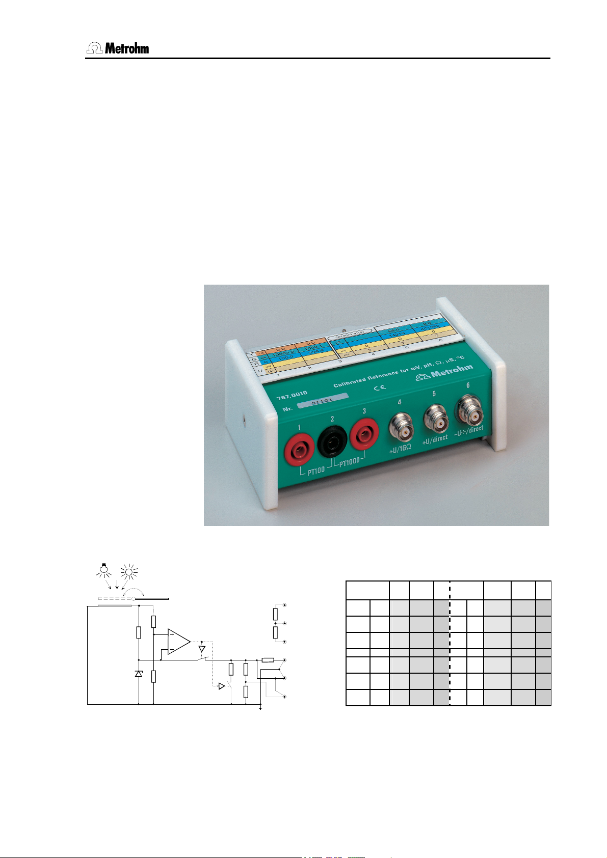
The measuring source 767.0010 Calibrated Reference for mV, pH,
Ω, µS, °C is a calibrated instrument for the quantities mentioned above.
It is connected instead of the electrodes and can be used for rapidly
and easily checking of the functioning and the basic accuracy of most
Metrohm instruments.
In addition the input resistance of high-impedance measuring amplifiers
(pH Meters, Titrators) and, for separate amplifiers, the insulation of the
reference point from the earth can be checked.
Fig. 1: 767 Calibrated Reference
U R G T U R G T
+U/1G
+U/direct
-U+/direct
(1)
(2)
(3)
(4)
(5)
(6)
solar cell
S1a
S1b
100 Ohm
1000 Ohm
1G
Pt 100
Pt 1000
Fig. 2 Functional scheme: Position "Voltage
source ON"
767 Calibrated Reference Instructions for Use 1
mV pH S :S °C mV pH S :S °C
100 10'000 0 100 10'000 0
1000 1000 0 1000 1000 0
(1200) 0 7 1G
1200 0 7 14'300 70
-341 12.7 0 7 460'000 2
Fig. 3: Label on cover
(exact values are given on the cover)
cover open ¦ cover closed
Page 6

1 Overview
1.2 Functional description
As mentioned before the input resistance of high-impedance measuring
amplifiers (pH Meters, Titrators) and, for separate amplifiers, the insulation of the reference point from the earth can be checked.
This is done using the potential of a reference diode (approx. 1200 mV)
on the one hand at output socket (5) +U/direct and on the other hand
a high-impedance resistor (1 GΩ) at socket (4) +U/1 GΩ. This potential
is also switched to socket (6) −U÷/direct by a divider. This means that
a lower potential (approx. 341 mV) with inverted polarity is also available; this can also be converted to a value within the pH scale (approx.
pH 12.7).
The reference diode is fed by a solar cell. This means that neither a
mains supply nor a battery is necessary and makes the instrument virtually maintenance-free. An internal potential monitor ensures that the
output potential is switched off under inadequate lighting conditions before the tolerance requirements are no longer fulfilled.
The solar cell can be covered and thus switched off. The potential
monitor then switches a second electronic switch so that the internal
resistance of the switched-off source is 14.3 kΩ. This resistance can be
used to check the current and voltage sources built into pH Meters and
Titrators in a very simple manner. The voltage divider at socket (6)
−U÷/direct gives a resistance of about 460 kΩ, which can also be used
for testing purposes.
For checking the temperature measuring amplifier the 0°C resistances
of the temperature sensors Pt 100 and Pt 1000 are built-in, see sockets (1), (2), (3). These are separated from the other circuits in the test
instrument. This means that no unwanted earthing loops can occur
when they are used.
This means that 4 resistance values which can be used for checking
conductivity meters.
For the 767 Calibrated Reference we have done without fine adjustment
and instead have entered the resulting exact values in the table on the
cover. In this way we have gained a considerable degree of accuracy
and stability. In addition we have converted the resistance values into
conductance (µS) and temperature (°C), and the potential into the exact
pH value wherever this makes sense. This means that it is possible to
compare the display of the instrument to be tested directly with the corresponding value in this table. Two different tables are provided for the
open and closed covers.
Practice has shown that problems are often caused by the electrode
cable. They are subjected to mechanical stress (tension, pressure, torsion, etc.) and on the other hand they constantly and unavoidably come
directly into contact with chemicals (spilt solutions, vapors, etc.). Nevertheless their insulation value must always remain exactly as good as
that at the measuring amplifier input. Such an exposed element must
therefore be included in a test at all costs. This is why this measuring
source is equipped with sockets which correspond to the plug head of
2 767 Calibrated Reference Instructions for Use
Page 7
1 Overview
Metrohm electrodes and means that a test can be carried out very easily:
Screw off cable at electrode plug-in head → plug into Calibrated
Reference → measure
If this check produces a variation from the expected result then it is not
immediately clear as to whether the error lies in the instrument to be
checked or in the cable. Therefore specially labeled cables are available in the accessories which are included with the instrument; these
can be temporarily used instead of the original cable (see list of cables
chap. 5.2). These accessory cables are also useful for sensors which
do not have a plug-in head.
Note
It must be mentioned here that under no circumstances can or should
the 767 Calibrated Reference replace the periodic maintenance of the
instrument, but should only be used for determining whether an error
is present or not if functional difficulties occur. In addition, the basic
accuracy and high impedance of the instrument can be checked at
regular intervals.
During maintenance the instrument is subjected to a far more stringent check (e.g. linearity of display and A/D converter, etc.). In addition the switches, motors, mechanical components, etc. are also checked for corrosion and wear and tear.
767 Calibrated Reference Instructions for Use 3
Page 8

2 General instrument handling
2 General instrument handling
2.1 Storage
It is best to store the Calibrated Reference in its own case (with closed
cover) together with its accessory cables. In this way it is protected
against dirt, mechanical stress and moisture.
2.2 Maintenance
The instrument needs no real maintenance (it also contains no batteries). Finger prints or other dirt on the solar cell should be removed with
a cloth which has been slightly moistened with window-cleaning liquid
or alcohol. The colored tables on the cover should not be exposed to
cleaning agents.
2.3 Calibration
The calibration certificate is printed on the cover and contains data required for retraceability purposes. The separately printed calibration
certificate also contains the dates of the last and next calibrations. We
recommend to carry out a service every 5 years.
It is best to send the instrument back to Metrohm for a new calibration.
Please include all cables belonging to the set so that they can also be
checked. It is expedient to transport the instrument in its own case,
which should be packed in suitable transport packing material.
2.4 ‘High-Impedance’, an important basic term
pH electrodes are potential sources with a very high internal resistance.
If possible, no current should flow from the source in order not to falsify
the measuring potential. This means that the whole measuring circuit
consisting of electrode, cable, plug, socket, switching element up to the
measuring amplifier itself must be extremely well insulated. Only high
quality insulation material such as Teflon, polyethylene, glass, siliconized ceramics, etc. come into question. The intention is to achieve
an insulation resistance of up to 10
quirement. This value can be regarded as being infinite in the following
observations. From the Figure 4, p. 5 it can be seen that the potential E
in the amplifier is always effective, even when R
bly with the temperature (which is normal with electrodes).
Minute contamination caused by atmospheric deposits or spilt liquids
can influence the insulation values.
What happens in such a case?
14
Ohm. This is quite an extreme re-
changes very noticea-
i
An on-load potential source is formed and there is therefore a potential
drop at R
amplifier will be falsified by this amount.
4 767 Calibrated Reference Instructions for Use
(see Fig. 5, p. 5). The measuring potential effective at the
i
Page 9

2 General instrument handling
(6)
(4)
Ri
R
E
input
Ri
R
E
Rx
input
Fig. 4: Unloaded potential source
Fig. 5: On-load potential source
If the electrode is now calibrated, i.e. the electrode parameters are determined, then the instrument is in reality being adapted to the electrode. This means that the previously determined error will also be
compensated. The measurement will again be correct.
Why make so much fuss when everything is back in order?
One must be aware of the fact that such contaminations form an extremely unstable resistance, whose value alters with the atmospheric
humidity, temperature and many other chance occurrences. The resistance can therefore vary greatly. Together with R
, which is strongly de-
i
pendent on the temperature, this gives a very unstable potential divider.
This is then no longer compensated, at best during the next electrode
calibration (and therefore again by chance). Because this error is covered up again at every calibration it is often not noticed for a long time,
although it produces false (and above all unstable) results.
From this it can be seen that a constant additional monitoring of the
high impedance of pH Meters and Titrators must be a basic concern of
quality assurance. However, this only makes sense when the most exposed element, the sensor cable, is included in the monitoring process.
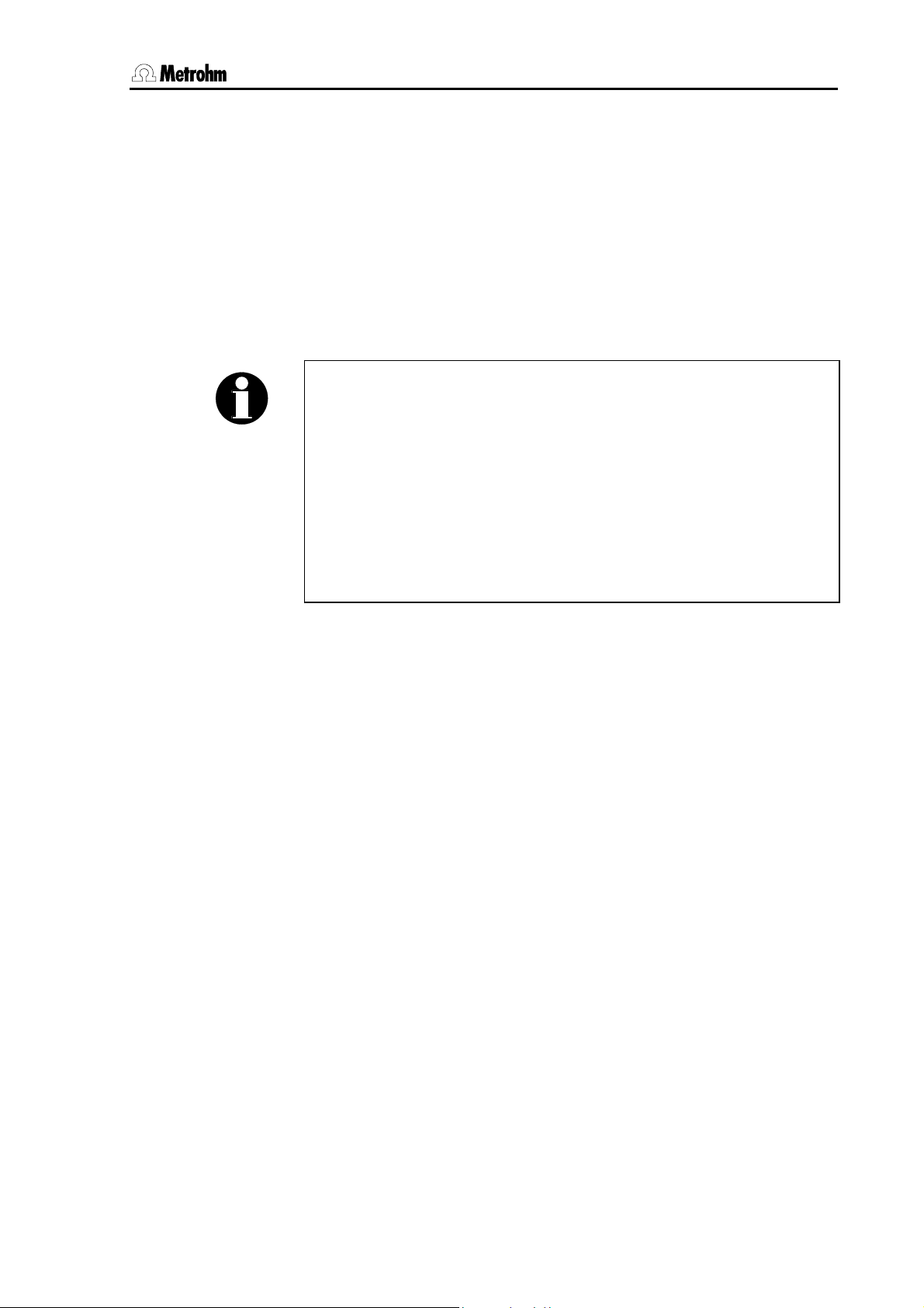
2.5 Measurement of the insulation resistance
Explanation for the steps 9-12, section 3.2.1 U/mV, pH.
R1
R2
Fig. 6: Measurement of the insulation resistance versus earthing
R
of the instrument to check via insulation of 6.2104.020 (6.2150.040)
Isol
cable and socket (5) is in parallel with R
With R
ok, e.g. > 108 Ω, there is no change in the display of the in-
Isol
strument to check.
using this interconnection.
2
767 Calibrated Reference Instructions for Use 5
Page 10

3 Procedure for checking instruments
3 Procedure for checking instru-
ments
3.1 Basics
The 767 Calibrated Reference is connected instead of the sensors, if
possible by means of the original sensor cable. If this is not possible
(e.g. for electrodes without a plug-in head) a list of suitable cables can
be found in the appendix, see chap. 5.2.
Each instrument can be checked with the Calibrated Reference within
the normal operating program and therefore also with the worked-out
methods. This has the advantage that methods and selected function
runs can be tested at the same time.
On the other hand the Instructions for Use of most instruments contain
a so-called diagnosis instructions, selective instructions for checking
the functioning of the instrument if malfunctioning is suspected. This type of check has the advantage that practically no (or only a very basic)
knowledge of operating the instrument is required. In addition, checking
the instrument by using the diagnosis instructions is usually significantly
faster.
This operating instructions for Calibrated Reference 767 are instructions
for checking the Metrohm instrument within the normal operating program. As the very large range of instruments means that for individual
instruments many different names and operating structures may have
been used, these instructions should therefore be interpreted logically.
It is not absolutely necessary to firmly screw down the electrode cap at
sockets (4), (5), (6); plugging it in is quite adequate.
3.2 pH Meters and Titrators
Place the Calibrated Reference on the bench near the sensor. Ensure
that light is not hindered from reaching the solar cell (no shadows from
cables or accessories). If necessary switch on the room lighting.
On the instrument to be tested the slope must be set to 1, pH
the measuring temperature to 25 °C for measuring the pH.
Please note:
• On the basis of the pH calibration the pH is determined from the
measured potential value. The pH checked here is therefore chiefly
relevant as a functionality check.
• If the endpoint is evaluated from a curve in a titration, the absolute
measured potential or pH value is not relevant.
• With KF titrators this check should be evaluated as a functionality
test.
to 7 and
as
6 767 Calibrated Reference Instructions for Use
Page 11

3 Procedure for checking instruments
3.2.1 U/mV, pH
carry out on instrument or sen-
sor:
1. screw off cable at sensor (for plug-in
head electrodes, otherwise use
corresponding accessory cable, see
chap. 5.2
2. connect sensor cable to
3. measure mV mV value (5)
4. open cover mV value (5) compare with
5. connect sensor cable to
6. connect sensor cable to
7. measure pH close cover pH value (6) set Uas to pH 7 if
8. open cover pH value (6) compare with
End of check
Steps 9...12 are of secondary importance. In general it is sufficient to carry out this check once per year.
For instruments with earthed circuits (e.g. all Titrinos and early series of 692/713) or for instruments without an earth socket (604,
704, 744) these steps are not relevant. Further Information to steps 9...12 can be found in chapter 2.5.
carry out on Calibrated
Reference:
close cover place sensor in
socket (5)
socket (4)
socket (6)
compare display
with:
permitted variation
mV value (6) observe polarity;
remarks
storage tube
permitted tolerance; note value
from value noted
under step 4:
±0.1 mV (shorttime larger deviations are normal)
(switch measuring
range if required);
compare with
permitted tolerance
necessary
permitted tolerance
9. measure mV connect sensor cable to
socket (5)
10. additionally connect cable
6.2150.020 (from accessories in case) to socket (6)
11. insert banana plug of cable in step
10 in earth socket of tested instrument. Banana plug of shielding re-
mains open.
12. remove cable from step 11 remove cable from
do not touch sockets (4),
(5), (6) during the measurement
socket (6)
If the variation of the measured values is too large then first exchange
the original sensor cable against the reference cable in the accessories.
When the check is finished recalibrate the electrodes.
note display as
under step 4
observe display
while connecting
the cable
permitted variation:
±0.1 mV display as
under step 5
(short-time larger
deviations are
normal)
767 Calibrated Reference Instructions for Use 7
Page 12

3 Procedure for checking instruments
3.2.2 Polarization current and voltage source
carry out on instrument or sen-
sor:
1. screw off cable at sensor close cover place sensor in
2. connect sensor cable to
3. set instrument to function Upol or
Ipol
carry out on Calibrated
Reference:
socket (5)
cover always remains closed calculate R value
compare display
with:
(5) according to
equation, see below
remarks
storage tube
compare with permitted tolerance;
take display resolution into account
If the variation of the measured values is too large then first exchange
the original sensor cable against the reference cable in the accessories.
Equations for the calculation:
U pol: I = (U/R) = selected Upol potential / Ω value (5)
I pol: U = (IxR) = selected Ipol current x Ω value (5)
For different instruments the different control limits according to the individual technical data must be observed → observe overload display.
Example:
1 µA x 14 345 Ω = 14.345 mV
Consider resolution of display!
3.2.3 Temperature (Pt 100/Pt 1000)
carry out on instrument or sen-
sor:
1. remove cable (with sensor) from
instrument
2. connect temperature measuring
input to Calibrated Reference with
2x banana cables (6.2150.000)
3. set instrument to temperature function
Note
During the pH measurement the two Pt 100 / Pt 1000 resistances at
sockets (1)....(3) can also be used at the same time with the pH mea-
surement (see above). Please note that the measuring temperature of
the instrument to be tested is approx. 0°C, while the information in the
table refers to 25°C. This must be converted accordingly.
For the Pt 1000 measuring input the following applies: value between
sockets (1) and (3) (R-Pt100 and R-Pt1000 in series) corresponds approximately to 25°C (for the exact individual value see certificate for
767.0010).
carry out on Calibrated
Reference:
close cover
depending on sensor, connect:
Pt 100 : sockets (1) (2)
Pt 1000: sockets (2) (3)
Pt 100 : sockets (1) (2) →
Pt 1000: sockets (2) (3) →
compare display
with:
°C value (1)(2)
°C value (2)(3)
remarks
compare with permitted tolerance
8 767 Calibrated Reference Instructions for Use
Page 13

3 Procedure for checking instruments
3.2.4 Tolerances
Instruments with digital display:
Potential U ± 1 mV
pH value ± 0.02
Temperature ± 0.5 °C
Polarization functionality test
Instruments with analog display:
The tolerance is within the reading accuracy.
Example:
Theoretical potential value: 1200.7 mV
Instrument resolution: 1 mV, i.e. nominal pot. value =1201 mV.
The test is OK when the read off value lies between 1200...1202 mV.
If the measurements lie outside the tolerances they should be repeated
with the reference cable from the accessories case.
If the measurements are still outside the tolerance range please contact
your local Metrohm agency to arrange for the instrument to be serviced.
3.3 Conductivity meters
Read off and note the cell constant, the temperature coefficient, and the
temperature on the instrument to be tested. Then set cell constant and
temperature coefficient to 1 and the temperature to the reference temperature valid for the instrument. Set the measuring frequency to
"automatic switchover".
Please note that a check carried out with this instrument and the diagnosis instructions (if available, see Instructions for Use of the Conductivity meter) may be quicker.
3.3.1 Conductance
carry out on instrument or sen-
sor:
1. screw off cable at sensor (for plug
head electrodes, otherwise use
corresponding accessory cable)
2. connect cable to socket (5)
3. set instrument to ‘conductivity’ function
4. connect cable to socket (6) G value (6) compare with per-
If further results are required:
5. remove measuring cable remove measuring cable
6. connect conductivity measuring
input to Calibrated Reference with
2x banana cables (6.2150.000)
carry out on Calibrated Reference:
close cover place sensor in
cover always remains closed G value (5) compare with per-
connect cable to sockets (1) (2)
connect cable to sockets (2) (3)
compare display with
G value (1)(2)
G value (2)(3)
remarks
storage tube
mitted tolerance
mitted tolerance
compare with permitted tolerance
767 Calibrated Reference Instructions for Use 9
Page 14

3 Procedure for checking instruments
3.3.2 Temperature
Checking the temperature, see chapter 3.2.3.
Note
During the measurement the two Pt 100 / Pt 1000 resistances at sock-
ets (1)....(3) can also be used at the same time as the conductance
measurement (see further up). Please note that the measuring temperature of the instrument to be tested is approx. 0°C, while the information in the table refers to 20°C. This must be converted accordingly.
When the test is finished the cell constant, temperature coefficient and
the temperature must be set again to their current values.
3.3.3 Tolerances
Instruments with digital display:
G value (5) ± 0.1 µS/cm
G value (6) ± 0.7 µS/cm
Temperature ± 0.5 °C
Instruments with analog display:
The tolerance lies within the reading accuracy.
If the measurements lie outside the tolerances they should be repeated
with the reference cable from the accessories case.
If the measurements are still outside the tolerance range please contact
your local Metrohm agency to arrange for the instrument to be serviced.
3.4 Rancimat 617 and 679
The Rancimat carries out conductivity measurements via the measuring
channels. The function of the measuring channels and the presentation
on the printer can be checked channel by channel by means of the
Calibrated Reference. The conductance can be read off from the display. By variation of the conductance the sensitivity of the measurement
can be shown on the printer in approximately the correct scale. The
temperature of the heating block plays no role in the following measurements (if the instrument has reached the operating temperature the
check can be started immediately). If this is not the case then the start
condition should be achieved (for 679: > 50°C).
The following test can be used as a functionality test.
carry out on instrument or sen-
sor:
1. unplug sensor from instrument close cover (Sensor can remain
2. plug in cable 6.2150.010 instead of
the sensor
carry out on Calibrated
Reference:
Plug in cable according to
diagram (see Fig. 7, p. 11)
so that 15.3 kΩ is obtained
compare display
with:
remarks
in the measuring
vessel)
10 767 Calibrated Reference Instructions for Use
Page 15

3 Procedure for checking instruments
3. note following parameters, then set
(example 679) :
temperature (see above) 50°C
cond. range 20 µS/cm
paper feed 20 cm/h
4. press start see G value for
5. wait until the printer is print-
6. if necessary repeat steps 1 - 5 for all
channels
Rancimat in certificate for 767.0010
(approx. 66 µS
G value (5)
ing out a channel which has
not been checked.
Replug cable (see Fig. 8,
p. 11), so that 14.3 kΩ ≅
approx. 69 µS is obtained
(see G value (5))
(ca. 69 µS 1))
allow all channels
to write out 2 - 3 x
(the zero line is
1)
shown in all chan-
)
nels)
allow all channels
to write out 2 - 3 x.
In the checked
channel the line will
be offset by the
amount of the alteration in conductance → check by
measuring with
ruler
1) Please consider the small number of decimal places in the display!
767
1 2
3 4 5 6
cable 6.2150.020
Rancimat
cable 6.2150.010
Fig. 7: Cable arrangement for 1st G value
(15.3 k
S
→approx. 66 :S)
767
1 2
cable 6.2150.010
3 4 5 6
cable 6.2150.020
Rancimat
Fig. 8: Cable arrangement for 2nd G value
(14.3 kS → approx. 69 :S)
767 Calibrated Reference Instructions for Use 11
Page 16

4 Checking by means of the diagnosis instructions
4 Checking by means of the di-
agnosis instructions
For most Metrohm instruments the so-called diagnosis instructions can
be found in the Instructions for Use. These are intended to provide the
possibility of testing an instrument with real or suspected malfunctions
in a simple way.
Until now when checking the measuring inputs the difficulty was always
experienced that for the quantities ‘potential’ and ‘resistance’ there was
often no suitable source available in the laboratories. In addition these
could no longer be connected to the high impedance sockets of our instruments. This difficulty has now been remedied in an outstanding
manner by our 767 Calibrated Reference.
In the diagnosis instructions of previous instruments the measuring
source 767 Calibrated Reference for mV, pH, Ω, µS, °C is not mentioned. However, it is easy to see how the instrument is to be connected
from the diagnosis instructions. The operation of the Calibrated Reference is almost self-evident and it is not difficult to derive the way in
which it is to be used from section 1 of these Instructions for Use (please note that polarization current and potential sources can be very
quickly checked in the diagnosis: connect sensor cable to socket (5),
close cover, start test, read off !)
For measurement at the differential inputs (e.g. Ind I / Ind II) it should be
noted that both inputs cannot be connected to the Calibrated Reference at the same time as this would short-circuit the output sockets.
This problem can be avoided by actually connecting both inputs, but alternately shorting one of the two inputs with cable 3.496.5070. However, should this appear to be expedient under exceptional circumstances, two different, but separately earthed instruments can be
connected to the same Calibrated Reference (to sockets (5) and (6)).
12 767 Calibrated Reference Instructions for Use
Page 17

5 Appendix
5 Appendix
5.1 Technical specifications
5.1.1 Measuring source
3 outputs with socket G:
socket (4)
socket (5)
socket (6)
Outputs with sockets B (temperature measurement):
socket (1)
socket (2)
socket (3)
The individual data are given in the two tables on the cover. Individual additional data
can be found in the certificate.
cover closed cover open
voltage resistance voltage
0 mV
0 mV
0 mV
(pH = 7)
100 S (Pt100)
1 GS
14.3 kS
460 kS
1000 S
(Pt 1000)
5.1.2 Temperature coefficient
cover closed cover open
socket (1)
socket (2)
socket (3)
socket (4) 100 ppm/°C 40 ppm/°C
socket (5) 100 ppm/°C 40 ppm/°C
socket (6) 100 ppm/°C 40 ppm/°C
25 ppm/°C 25 ppm/°C
25 ppm/°C
approx. 1200 mV
approx. 1200 mV
approx. - 341 mV
(pH = 12.7)
25 ppm/°C
5.1.3
767 Calibrated Reference Instructions for Use 13
Longterm stability (2 years)
cover closed cover open
socket (1)
socket (2)
socket (3)
socket (4) 5 ‰ 1.5 ‰
socket (5) 5 ‰ 1.5 ‰
socket (6) 5 ‰ 1.5 ‰
1.3 ‰ 1.3 ‰
6 ‰
6 ‰
Page 18

5 Appendix
5.1.4 Ambient temperature
Nominal working range 5 ... 40 °C
Storage – 20 ... 60 °C
Transport – 40 ... 60 °C
5.1.5 Safety specifications
Construction and testing according to IEC publication 1010, protection class 3
5.1.6 Electricity supply
Solar cells (no batteries)
5.1.7 Dimensions
Width
Height
Depth
Weight
Weight (with accessories)
125 mm
45 mm
85 mm
approx. 350 g
approx. 1 kg
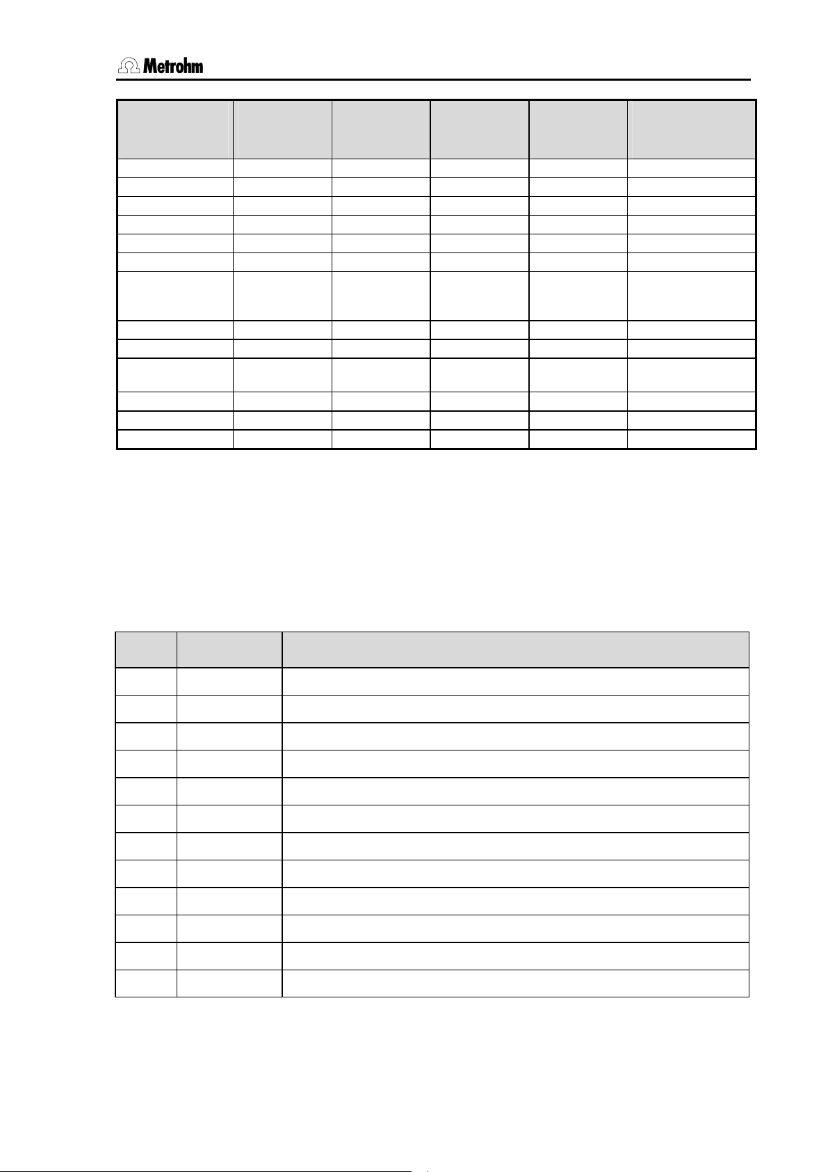
5.2 Cables for connecting 767 – instrument X
Please note that the cables in the 767.0010 accessories carry an ID and therefore
have a new ordering number (see title lines).
ordering number of
original cable
with ID
Conductometers
527 X
587 X
644 X
660, 712 X X
pH Meters
500, 510 X X
512 X (X)
520, 532, 588, 603 X
604 X
605, 610 X X
620, 632 X
654 X X X
691, 692, 713 X X X
704, 744 X X
6.2104.020
6.2150.040
6.2104.050
6.2150.030
6.2104.080
6.2150.020
2x 6.2106.020
2x 6.2150.000
6.2150.010
14 767 Calibrated Reference Instructions for Use
Page 19
5 Appendix
ordering number of
original cable
with ID
Titrators
526 X
536 X X
576 X
636, 670 X X
672, 682, 686 X X
702, 716, 718, 719,
720, 721, 726, 736,
751, 785
KF instruments
678 X X
684, 701, 737, 758,
784
707, 768 X
Rancimat
617, 679 X
6.2104.020
6.2150.040
X X
X
6.2104.050
6.2150.030
6.2104.080
6.2150.020
2x 6.2106.020
2x 6.2150.000
6.2150.010
With newer instruments you can normally use the cables 6.2150.040 (pH/mV measurement) and 6.2150.000 (temperature measurement).
5.3 Standard equipment
Immediately upon receipt of the instrument please check that the delivery is complete.
Order no. 2.767.0010
The following accessories are included:
no. order no. Description
1 1.767.0010 Calibrated Reference for mV, pH, S, :S, °C
1 6.2103.130 Adapter red, 2 mm plug / 4 mm socket
1 6.2103.140 Adapter black, 2 mm plug / 4 mm socket
2 6.2150.000 Cable plug B / plug B
1 6.2150.010 Cable plug B 2x / plug DIN
1 6.2150.020 Cable plug B 2x / plug head G
1 6.2150.030 Cable plug head G / plug E
1 6.2150.040 Cable plug head G / plug F
1 6.2716.020 Case for 767 Calibrated Reference
1 8.767.1023 Instructions for Use for 767 Calibrated Reference
1 8.767.1203 Quick references for 767 Calibrated Reference
1 Certificate for 767 Calibrated Reference
767 Calibrated Reference Instructions for Use 15
Page 20

5 Appendix
5.4 Warranty and conformity
5.4.1 Warranty
The warranty on our products is limited to defects that are traceable to
material, construction or manufacturing error which occur within 12
months from the day of delivery. In this case the defects will be rectified
in our workshops free of charge. Transport costs are to be paid by the
customer.
For day and night operation the warranty is limited to 6 months.
Glass breakage in the case of electrodes or other parts is not covered
by the warranty. Checks which are not a result of material or manufacturing faults are also charged during the warranty period. For parts from
outside manufacturers, insofar as these constitute an appreciable part
of our instrument, the warranty stipulations of the manufacturer in question apply.
With the regard to the guarantee of accuracy the technical specifications in the instruction manual are authoritative.
Concerning defects in materials, construction or design as well as the
absence of guaranteed features the purchaser has no rights or claims
except those mentioned above.
If damage of the packaging is evident on receipt of a consignment or if
the goods show signs of transport damage after unpacking, the carrier
must be informed immediately and a written damage report demanded.
Lack of an official damage report releases Metrohm from any liability to
pay compensation.
If any instruments and parts have to be returned then the original packaging should be used if at all possible. This applies above all to instruments and electrodes. Before embedment in wood shavings or similar
material the parts must be packed in a dustproof package (for instruments the use of a plastic bag is essential). If open assemblies are included that are sensitive to electromagnetic voltages (e. g. data interfaces, etc.) then these must be returned in the associated original protective packaging (e. g. conductive protective bag). (Exception: assemblies with a built-in voltage source belong in non-conductive protective packaging).
For damage which arises as a result of non-compliance with these instructions no warranty responsibility whatsoever will be accepted by
Metrohm.
16 767 Calibrated Reference Instructions for Use
Page 21

5 Appendix
5.4.2 Declaration of Conformity
This is to certify the conformity to the standard specifications for electrical appliances and accessories,
as well as to the standard specifications for security and to system validation issued by the manufacturing company.
Name of commodity
767 Calibrated Reference
Description Instrument for verification of measured values: tension U/mV, pH, resistance, tempera-
ture, conductance.
This instrument has been built and has undergone final type testing according to the standards:
Electromagnetic compatibility: Emission
EN50081-1/92, EN55022/class B
EN55011/class B Generic emission
Electromagnetic compatibility: Immunity
EN50082-1/92 Immunity
IEC801-2/91 (level 2) Static discharge
IEC801-3, ENV50140/93+ENV50204/93 (level 2) Radiated rf electromag.field immunity
CH-9101 Herisau/Switzerland
E-Mail info@metrohm.com
www.metrohm.com
Safety specifications
IEC1010 class3, EN61010 class3, UL3101-1, EN60947:IP31
The instrument meets the requirements of the CE mark as contained in the EU directives 89/336/EWG und 73/23/EWG
EN 50081-1 Electromagnetic compatibility, basic specification Emitted Interference
EN 50082-1 Electromagnetic compatibility, basic specification Interference Immunity
EN 61010 Safety requirements for electrical laboratory measurement and control equipment
Metrohm Ltd. is holder of the SQS-certificate of the quality system ISO 9001 for quality assurance in
design/development, production, installation and servicing.
The technical specifications are documented in the instruction manual.
Herisau, March 14, 1998
Dr. J. Frank Ch. Buchmann
Development Manager Production and
Responsible for Quality Assurance
and fulfils the following specifications:
767 Calibrated Reference Instructions for Use 17
Page 22

5 Appendix
5.4.3 Quality Management Principles
Metrohm Ltd., CH-9101 Herisau, Switzerland
CH-9101 Herisau/Switzerland
E-Mail info@metrohm.com
Internet www.metrohm.com
Metrohm Ltd. holds the ISO 9001 Certificate, registration number 10872-02, issued by
SQS (Swiss Association for Quality and Management Systems). Internal and external audits are carried out periodically to assure that the standards defined by Metrohm’s QM
Manual are maintained.
The steps involved in the design, manufacture and servicing of instruments are fully documented and the resulting reports are archived for ten years. The development of software for PCs and instruments is also duly documented and the documents and source
codes are archived. Both remain the possession of Metrohm. A non-disclosure agreement may be asked to be provided by those requiring access to them.
The implementation of the ISO 9001
quality system is described in Metrohm’s
QM Manual, which comprises detailed
instructions on the following fields of
activity:
Instrument development
The organization of the instrument design, its planning and the intermediate
controls are fully documented and traceable. Laboratory testing accompanies all
phases of instrument development.
Software development
Software development occurs in terms of
the software life cycle. Tests are performed to detect programming errors
and to assess the program’s functionality in a laboratory environment.
Components
All components used in the Metrohm
instruments have to satisfy the quality
standards that are defined and implemented for our products. Suppliers of
components are audited by Metrohm as
the need arises.
Manufacture
The measures put into practice in the
production of our instruments guarantee
a constant quality standard. Production
planning and manufacturing procedures,
maintenance of production means and
testing of components, intermediate and
finished products are prescribed.
Customer support and service
Customer support involves all phases of
instrument acquisition and use by the
customer, i.e. consulting to define the
adequate equipment for the analytical
problem at hand, delivery of the equipment, user manuals, training, after-sales
service and processing of customer
complaints. The Metrohm service organization is equipped to support customers in implementing standards such
as GLP, GMP, ISO 900X, in performing
Operational Qualification and Performance Verification of the system components or in carrying out the System Validation for the quantitative determination
of a substance in a given matrix.
18 767 Calibrated Reference Instructions for Use
Page 23

6 Index
6 Index
A
Ambient temperature ..............14
C
Cable.......................................14
Calibration
767...................................4
Electrode .....................5, 7
Cleaning
Solar cell .......................... 4
Conductivity meter................2, 9
Conductometer.......................14
Connecting cable....................14
Cover ....................................2, 4
D
Depth ......................................14
Dimensions.............................14
E
Electricity supply.....................14
Electrode
Calibrate ......................5, 7
H
Height .....................................14
High-Impedance.......................4
I
ISO 9001 .................................17
K
KF instrument..........................15
M
Maintenance .........................3, 4
P
pH Meter .............................6, 14
pH value.................................... 6
Polarization current ...................8
Polarization potential ................8
Potential .................................... 6
Pt 100/Pt 1000 ......................2, 8
R
Rancimat........................... 10, 15
S
Safety specifications...............14
Solar cell ...................................2
Cleaning...........................4
Standard equipment ...............15
Storage .....................................4
T
Temperature .............................8
Temperature coefficient ..........13
Temperature sensor..................2
Titrator.................................6, 15
Tolerance
:S/cm, °C ......................10
mV, pH, °C .......................9
W
Warranty.................................. 16
Weight.....................................14
Width.......................................14
767 Calibrated Reference Gebrauchsanweisung 19
 Loading...