

Page 1
CH-9101 Herisau/Switzerland
Tel. ++41 71 353 85 85
Fax ++41 71 353 89 01
Internet www.metrohm.ch
E-Mail info@metrohm.ch
766 IC Sample Processor
DES FUSIBLES DE 250V
USE ONLY WITH 250V
100-120V
UNIQUEMENT AVEC
FUSES/EMPLOYER
MetrohmMetrohm
220-240V
8.766.1003 Instructions for Use
30.06.1998 / dö
Page 2

Table of contents
Table of contents
1 Introduction....................................................................................... 1
1.1 Instrument description................................................................... 1
1.2 Parts and controls........................................................................... 2
1.3 Information about the Instructions for Use................................ 5
1.3.1 Organization ............................................................................ 5
1.3.2 Notation and pictograms ........................................................ 6
1.4 Support documentation .................................................................. 7
1.4.1 Application Bulletins................................................................ 7
1.4.2 Application Notes.................................................................... 7
1.5 Safety notes....................................................................................... 7
1.5.1 Electrical safety ....................................................................... 7
1.5.2 General safety rules ................................................................ 8
2 Installation......................................................................................... 9
2.1 Setting up the instrument............................................................... 9
2.1.1 Packaging................................................................................ 9
2.1.2 Check....................................................................................... 9
2.1.3 Location................................................................................... 9
2.1.4 Arrangement of the instruments ............................................. 9
2.2 Mains connection........................................................................... 10
2.2.1 Setting the mains voltage ..................................................... 10
2.2.2 Fuses ..................................................................................... 11
2.2.3 Mains cable and mains connection...................................... 11
2.2.4 Switching the instrument on/off ............................................ 11
2.3 Attaching the accessories............................................................ 12
2.3.1 Connecting the swing head.................................................. 12
2.3.2 Connecting the keyboard ..................................................... 12
2.3.3 Installing the plug cover........................................................ 12
2.3.4 Installing the splash protection............................................. 13
2.3.5 Installing the needle .............................................................. 13
2.3.6 Placing the sample rack........................................................ 14
2.3.7 Adjusting the sample rack .................................................... 14
2.3.8 Tubing connections 766 – 733 ............................................. 16
2.3.9 Tubing connections 766 – 754 ............................................. 18
2.3.10 Fixing tubing and cables..................................................... 18
766 IC Sample Processor
I
Page 3

Table of contents
3 Operating tutorial..................................................................... 27
2.4 Connection of devices to the remote interface........................ 19
2.4.1 General information on remote interface...............................19
2.4.2 Connection cables .................................................................19
2.4.3 IC system without suppression .............................................20
2.4.4 IC system with suppression with 766 as "Master".................20
2.4.5 IC system with suppression with PC as "Master"..................21
2.4.6 IC system for simultaneous anion/cation determination ......21
2.4.7 IC system with sample dialysis..............................................22
2.5 Connection of devices to the RS232 interface......................... 23
2.5.1 General information on RS232 interface ...............................23
2.5.2 Connection of a printer ..........................................................24
3.1 Prerequisites / Preparations......................................................... 27
3.2 Configuration .................................................................................. 28
3.3 Rack configuration......................................................................... 29
3.4 Methods............................................................................................ 31
3.5 "Tracing".......................................................................................... 31
4 Operation.......................................................................................... 35
4.1 Fundamentals of operation.......................................................... 35
4.1.1 Display....................................................................................35
4.1.2 Keyboard................................................................................36
4.1.3 Overview of key functions......................................................37
4.1.4 Instrument dialog ...................................................................46
4.1.5 Data entry ...............................................................................48
4.1.6 Text entry................................................................................49
4.2 Basic settings ................................................................................. 51
4.2.1 Configuration – <CONFIG> key...........................................51
4.2.2 Locking keyboard functions ..................................................55
4.3 Methods............................................................................................ 57
4.3.1 Structure of a method ............................................................57
4.3.2 Method parameters – <PARAM> key..................................58
4.3.3 Programming of sequences ..................................................60
4.3.4 LEARN mode..........................................................................61
4.3.5 TRACE function......................................................................61
4.3.6 Commands for sequences ....................................................62
4.3.7 Process control ......................................................................67
4.3.8 User defined methods ...........................................................68
4.3.9 POWERUP method................................................................69
4.4 Manual operation............................................................................ 70
4.4.1 Turning the sample rack / Positioning the samples..............70
4.4.2 Moving the lift .........................................................................70
II
766 IC Sample Processor
Page 4

Table of contents
4.4.3 Setting the sample position .................................................. 71
4.4.4 Pump control......................................................................... 71
4.4.5 Display interface signals ....................................................... 71
4.4.6 Interface control..................................................................... 72
4.4.7 Print out reports..................................................................... 73
4.5 Sample racks................................................................................... 75
4.5.1 Standard rack (6.2041.430) .................................................. 75
4.5.2 Magnetic code....................................................................... 75
4.5.3 Rack data .............................................................................. 76
4.5.4 Special beakers..................................................................... 78
4.6 Standard methods.......................................................................... 79
4.6.1 Method "PC" .......................................................................... 79
4.6.2 Method "PC Seg"................................................................... 80
4.6.3 Method "SP"........................................................................... 81
4.6.4 Method "SP Seg" ................................................................... 82
4.6.5 Method "An Cat" .................................................................... 83
4.6.6 Method "AnCatSeg"............................................................... 84
4.6.7 Method "Preconc".................................................................. 86
4.6.8 Method "Dialysis"................................................................... 87
5 Interfaces.........................................................................................89
5.1 Remote interface............................................................................. 89
5.1.1 Pin assignment of the remote socket:.................................. 89
5.1.2 Functional characteristics ..................................................... 90
5.2 RS232 interface............................................................................... 93
5.2.1 General rules for remote control........................................... 93
5.2.2 Call-up of objects .................................................................. 94
5.2.3 Trigger.................................................................................... 95
5.2.4 Status messages................................................................... 96
5.2.5 Error messages..................................................................... 97
5.2.6 Remote control commands .................................................. 98
5.2.7 Data transmission protocol................................................. 105
5.2.8 Handshake .......................................................................... 106
5.2.9 Pin assignment.................................................................... 109
5.2.10 RS232 error rectification.................................................... 110
6 Appendix.........................................................................................111
6.1 Error messages............................................................................. 111
6.2 Technical data............................................................................... 113
6.3 Maintenance and servicing......................................................... 115
766 IC Sample Processor
6.3.1 Maintenance by Metrohm service ...................................... 115
6.3.2 Care of the unit.................................................................... 115
6.3.3 Replacing the pump tubing ................................................ 116
III
Page 5

Table of contents
6.4 Diagnosis....................................................................................... 117
6.4.1 General Information .............................................................117
6.4.2 Preparing the instrument .....................................................118
6.4.3 Working memory (RAM).......................................................119
6.4.4 Display..................................................................................119
6.4.5 Keyboard ..............................................................................120
6.4.6 Remote interface..................................................................121
6.4.7 RS232 interface....................................................................122
6.4.8 External Bus interface ..........................................................122
6.4.9 Beeper ..................................................................................123
6.4.10 Rack code recognition.......................................................123
6.5 Initialize data memory ................................................................. 124
6.6 Validation / GLP............................................................................ 126
6.7 Warranty and conformity............................................................ 127
6.7.1 Warranty ...............................................................................127
6.7.2 EU Declaration of conformity...............................................128
6.7.3 Certificate of conformity and system validation ..................129
6.8 Standard equipment .................................................................... 130
6.9 Optional accessories................................................................... 132
6.10 Index ............................................................................................. 133
List of figures
Fig. 1: Side view of the 766 IC Sample Processor ...................................................2
Fig. 2: Rear of the 766 IC Sample Processor .......................................................... 4
Fig. 3: Setting the mains voltage.......................................................................... 11
Fig. 4: Keyboard connection ...............................................................................12
Fig. 5: Installing the splash protection.................................................................. 13
Fig. 6: Needle installation.................................................................................... 14
Fig. 7: Sample rack placing................................................................................. 14
Fig. 8: Adjusting the sample rack ....................................................................... 15
Fig. 9: Installing the pump tubing ........................................................................17
Fig. 10: Opening chain links.................................................................................. 18
IV
Fig. 11: Interconnection with IC system without suppression...................................20
Fig. 12: Interconnection with IC system with suppression with 766 as "Master"......... 20
Fig. 13: Interconnection with IC system with suppression with PC as "Master".......... 21
Fig. 14: Interconnection with IC system for anion/cation system .............................. 21
Fig. 15: Interconnection with IC system with dialysis............................................... 22
Fig. 16: Connection possibilities for the RS232 interface ........................................ 23
Fig. 17: Schematic representation of the instrument dialog .....................................47
Fig. 18: Installation of the preconcentration column ............................................... 86
766 IC Sample Processor
Page 6
1 Introduction
1.1 Instrument description
The 766 IC Sample Processor can be used for automating ion chromatographic determinations, especially in combination with the
Metrohm IC system instruments. The 127 sample tubes with a volume
of up to 11 mL are arranged on the sample rack in three rows, which
guarantees easy access and unrestricted programming. Two additional
rinsing positions allow sample introduction free from crosscontamination even with widely varying sample matrices. If the 766 IC
Sample Processor is used together with the 732 IC Detector and the
733 IC Separation Center, various injections are possible from a single
sample tube, depending on the sample size. Sample tubes made of
polypropylene are standard. To protect the samples from external contamination, the tubes can be hermetically sealed.
1.1 Instrument description
Sample introduction from the 766 IC Sample Processor is achieved by
means of its integrated peristaltic pump. The sample is conveyed by
the pump through the capillary into the sample loop of the injector located within the 733 IC Separation Center. A steel needle for sealed or
a PEEK needle for open sample tubes can be used alternatively. Owing
to the relatively large volume of the sample tubes the 766 IC Sample
Processor can also be used for applications with enrichment columns,
dialysis (with the 754 Dialysis Unit) or simultaneous anion/cation determinations.
The sequences for the processing of each sample are freely definable
within broad boundaries. The same is true for the start and final sequences that are executed once either before or at the end of a sample
series. With the help of the LEARN mode, which is provided for creating
process methods, methods can be created easily and stored as user
methods.
Preprogrammed standard methods for the most common modes of
operation allow to use the 766 IC Sample Processor directly, with only
little programming effort. The time frame can be given by the IC Sample
Processor; alternatively, the whole sequence can be managed by the
«IC Metrodata» remote control software via the «Queue» (sample table). The RS232 interface built in as standard allows remote control of
the IC Sample Processor from a PC.
766 IC Sample Processor
1
Page 7
1 Introduction
1.2 Parts and controls
55 66 77 88 99
44
33
22
11
Always install splash
protection!
1010
1111
1212
1313
1414
1515
1616
1717
1111
2828
2727
2626
2525
2424
MetrohmMetrohm
DES FUSIBLES DE 250V
USE ONLY WITH 250V
100-120V
UNIQUEMENT AVEC
FUSES/EMPLOYER
220-240V
Always install plug cover!
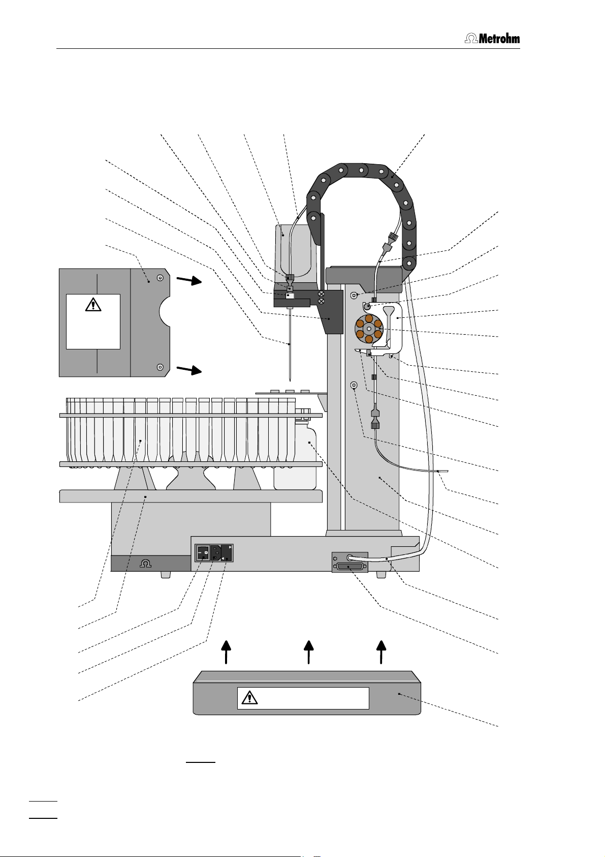
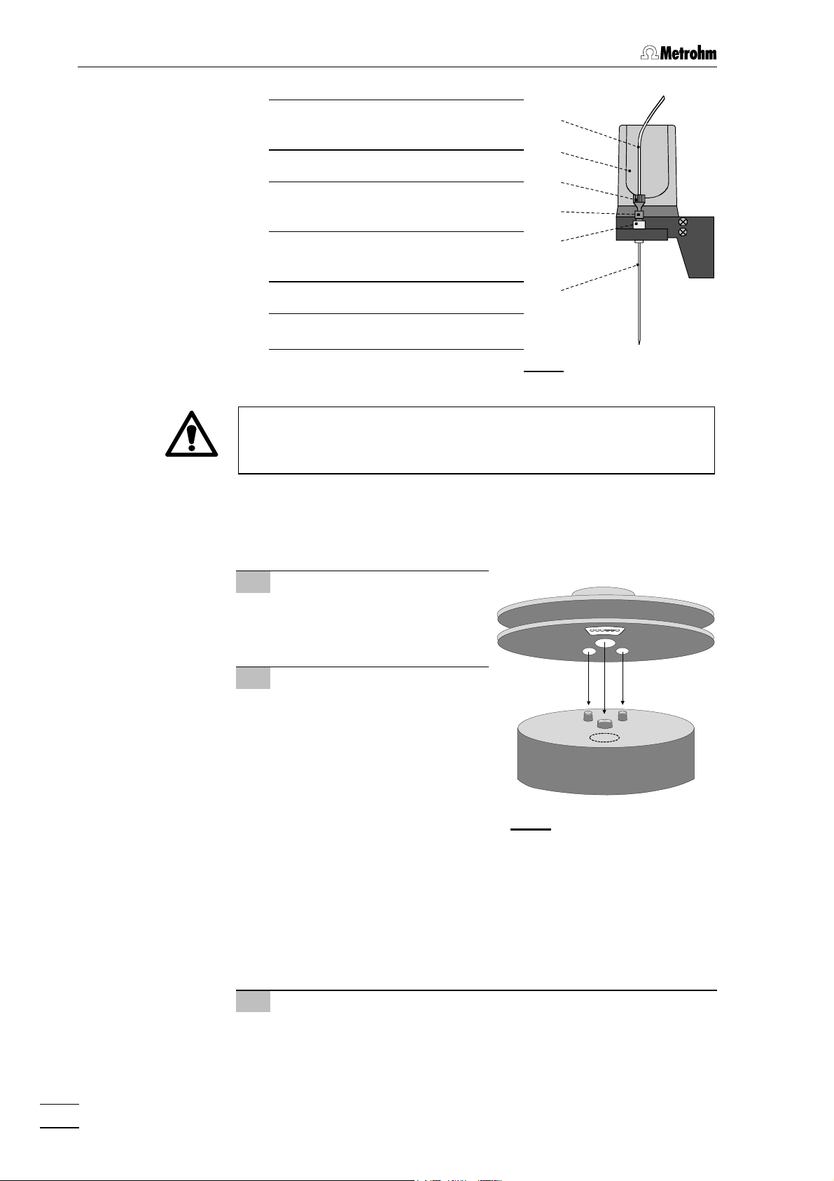
Fig. 1: Side view of the 766 IC Sample Processor
1818
1919
2020
2121
2222
2323
2
766 IC Sample Processor
Page 8

1.2 Parts and controls
11 Splash protection
(6.2751.040)
Must be installed always in
operation!
22 Needle
Steel needle (6.2624.000) or
PEEK needle (6.1835.000)
33 Lift
With swing head attached
44 Needle holder
(attached)
55 PEEK compression fitting
(4.766.4070)
For peek capillary 88
66 PEEK compression fitting
(6.2744.010)
1515 Contact pressure lever
For adjusting the contact pressure
1616 Holding clamp
For locking the tubing cartridge into
place
1717 Snap-action lever
For releasing the tubing cartridge
1818 PEEK capillary (6.1831.060; 1 m)
For conveying the sample to the
injection valve of the 733 IC Separation Center
1919 Tower
2020 PE bottle (6.1608.080; 300 mL)
77 Swing head
(attached)
88 PEEK capillary (6.1831.050;
40 cm)
Connection needle – pump
tubing
99 Guide chain
For fixing tubings and cables
1010 Pump tubing (6.1826.040)
For conveying the sample
1111 Screw thread for splash
protection
1212 Mounting pin
For attaching the tubing
cartridge
2121 Connection cable for swing head
Attached, incl. branch plug for remote
connection
2222 Remote connection
2323 Plug cover (6.2752.010)
2424 Fuse holder
Changing the fuses, see section 2.2.2
2525 Mains connection plug
Mains connection, see section 2.2.3
2626 Mains switch
For switching the instrument on/off:
I = ON 0 = OFF
1313 Tubing cartridge (6.2755.000)
For 6.1826.0X0 pump tubing
1414 Pump drive
Roller head with contact rollers
766 IC Sample Processor
2727 Sample rack (6.2041.430)
2828 PP sample tube (6.2743.050)
(can be sealed with 6.2743.060 PE
caps)
3
Page 9
1 Introduction
99
2929
1313
2929
2020
2323
2929
1919
11
2929
2828
2020
3030
Type 1.766.
RS 232 Keyboard
Made by Metrohm Herisau Switzerland
3131
3232
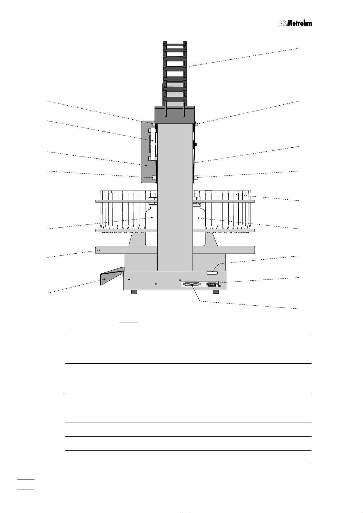
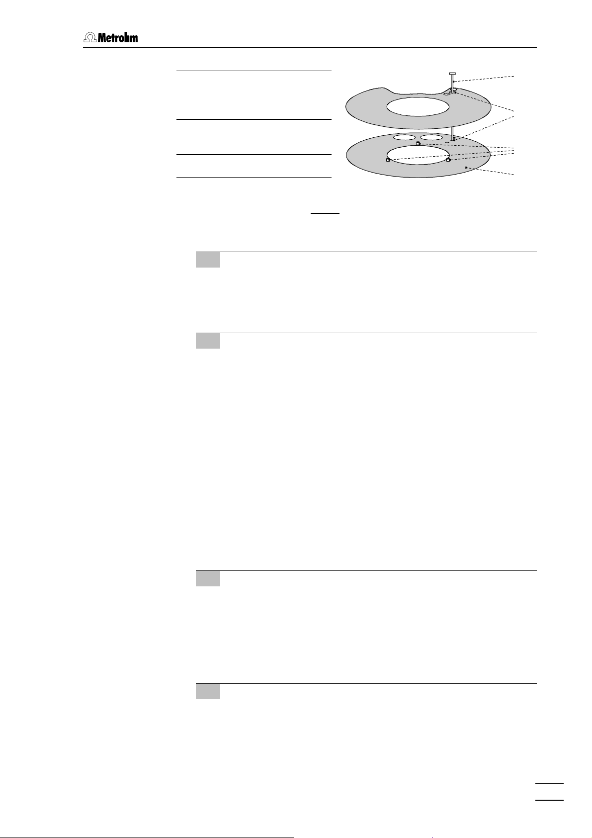
Fig. 2: Rear of the 766 IC Sample Processor
11 Splash protection (6.2751.040)
Must be installed always in
operation!
99 Guide chain
For fixing tubings and cables
1313 Tubing cartridge (6.2755.000)
For 6.1826.0X0 pump tubing
1919 Tower 3030 Serial number
2020 PE bottle (6.1608.080; 300 mL) 3131 Keyboard connection
2323 Plug cover (6.2752.010) 3232 RS232 connection
4
2727 Sample rack (6.2041.430)
2828 PP sample tube (6.2743.050)
(can be sealed with 6.2743.060 PE
caps)
2929 Mounting screws for splash
protection
766 IC Sample Processor
Page 10

1.3 Information about the Instructions for Use
1.3 Information about the Instructions for Use
Please read through these Instructions for Use carefully before operating the 766 IC Sample Processor. The Instructions for Use contain
information and warnings to which the user must pay attention in order
to assure safe operation of the instrument.
1.3.1 Organization
These 8.766.1003 Instructions for Use for the 766 IC Sample Processor provide a comprehensive overview of the installation, startup procedure, operation, fault rectification and technical specifications of this
instrument. The Instructions for Use are organized as follows:
Section 1 Introduction
Description of the instrument, parts and controls,
safety notes
Section 2 Installation
Mains connection, attachment of accessories,
connection of external devices
Section 3 Operating tutorial
Introduction to the operation
Section 4 Operation
Detailed description of display, keyboard, methods,
manual operation, sample racks, standard methods
Section 5 Interfaces
Remote interface, RS232 interface and
remote control language
Section 6 Appendix
Error messages, technical data, maintenance
and servicing, diagnosis, warranty, declaration
of conformity, standard equipment, optional
accessories, index
To find the information you require about the instruments please use
either the Table of contents or the Index at the back. The 8.766.1013
Quick Reference Guide is suitable for use as a reference work for
daily use as it explains the most important parameters and key functions.
766 IC Sample Processor
5
Page 11
1 Introduction
1.3.2 Notation and pictograms
The following notations and pictograms (symbols) are used in these Instructions for Use:
<PUMP> Switch or key
1515 Part or control of 766
8989 Part or control of 732/733
2626 Part or control of 754
'rack number' Parameter or entry value
at 766 IC Sample Processor
******** counter 0/127
PUMP- ready
Display
Text in keyboard display of 766
IC Sample Processor
Hazard
This symbol draws attention to
a possible danger to life or
injury if the associated
directions are not followed
correctly.
Warning
This symbol draws attention to
possible damage to instruments
or instrument parts if the associated directions are not followed correctly.
Caution
This symbol marks important
information. Read these directions before continuing.
Comment
This symbol marks additional
information and tips.
6
766 IC Sample Processor
Page 12
1.4 Support documentation
1.4.1 Application Bulletins
The «Application Bulletin» is a collection of analytical methods, application examples and literature references. Of Metrohm's approximately
200 Application Bulletins, 34 currently refer to ion chromatography. All
these Application Bulletins are available on request free of charge from
your Metrohm supplier.
You will find an updated list of the Application Bulletins at any time under «http://www.metrohm.ch».
1.4.2 Application Notes
The «Application Notes» present application information in concentrated form, i.e. on maximum 2 pages. There are currently 88 Application Notes (in English) in the field of ion chromatography. You can order
these free of charge from your Metrohm supplier or view them in the
Internet under «http://www.metrohm.ch» and copy them from there.
1.4 Support documentation
1.5 Safety notes
1.5.1 Electrical safety
While electrical safety in the handling of the 766 IC Sample Processor is
assured in the context of the specifications IEC 1010-1 (protection class
1, degree of protection IP40), the following points should be noted:
• Mains connection
Set the mains voltage and check the mains fuse and mains
connection in accordance with the instructions in section 2.2.
• Opening the 766 IC Sample Processor
To avoid all danger of coming into contact with live components do
not open the instrument or remove any parts when the 766 IC Sample
Processor is connected to the power supply. Always disconnect the
instrument from all voltage sources before you open it and ensure that
the mains cable is disconnected from mains connection 2525 !
766 IC Sample Processor
7
Page 13
1 Introduction
• Protection against static charges
Electronic components are sensitive to static charging and can be
destroyed by discharges. Before you touch any of the components
inside the 766 IC Sample Processor, you should earth yourself and
any tools you are using by touching an earthed object (e.g. housing of
the instrument or a radiator) to eliminate any static charges which
exist.
1.5.2 General safety rules
• Install splash protection
To avoid any danger of injury by the needle, the splash protection
must always be installed when operating the 766 IC Sample Processor!
• Install plug cover
To prevent any contamination of the mains and remote connection by
spilled solvents or chemicals, the plug cover must always be installed
when operating the 766 IC Sample Processor !
• Do not use caps together with the PEEK tube
If you are using the 6.1835.000 PEEK needle, the sample tubes may
not be sealed with caps because they cannot be pierced by the PEEK
needle and the needle may be damaged thereby.
• Handling of solvents
Check the pump tubing and all input and output leads periodically for
possible leaks. Follow the relevant instructions regarding the handling
of flammable and/or toxic solvents and their disposal.
• Regular exchange of pump tubings
Pump tubings constitute consumable material and must be replaced
from time to time (see section 6.3.3). Suitable measures must be
taken so that any leak which might occur in the pump tubing or
connections during unattended operation will cause no damage
(collection device for any liquid which may leak out).
8
766 IC Sample Processor
Page 14
2 Installation
2.1 Setting up the instrument
2.1.1 Packaging
The 766 IC Sample Processor is supplied together with the separately
packed accessories in special packagings containing shock-absorbing
foam linings designed to provide excellent protection. The actual instrument is packed in an evacuated polyethylene bag to prevent the ingress of dust. Please store all these special packagings as only they
can assure damage-free transport of the instrument.
2.1 Setting up the instrument
2.1.2 Check
After receipt, immediately check whether the shipment is complete and
undamaged (compare with delivery note and list of accessories in sec-
tion 6.8). In the case of transport damage, see instructions in section
6.7.1 "Warranty".
2.1.3 Location
Position the instrument in the laboratory at a location convenient for operation, free from vibrations and protected against a corrosive atmosphere and contamination by chemicals.
Do not operate the 766 IC Sample Processor without splash protection 11 and plug cover 2323 being installed!
2.1.4 Arrangement of the instruments
To make the connection between needle 22 and the injection valve at
the 733 IC Separation Center with the peek capillary 1818 (length 1 m)
supplied, position the 766 IC Sample Processor immediately on the left
side of the IC system.
766 IC Sample Processor
Take precautions to ensure that any leaks from pump tubings or
connections cannot cause more damage.
9
Page 15
2 Installation
2.2 Mains connection
Follow the instructions below for connecting to the power supply. If
the instrument is operated with the mains voltage set wrongly and/or
wrong mains fuse there is a danger of fire!
2.2.1 Setting the mains voltage
Before switching on the 766 IC Sample Processor for the first time,
check that the mains voltage set on the instrument (see Fig. 2) matches
the local mains voltage. If not, reset the mains voltage on the instrument as follows:
Disconnect mains cable
1
Disconnect mains cable from mains connection plug 2525 of the
766 IC Sample Processor.
Remove fuse holder
2
Using a screwdriver, loosen fuse holder 2424 beside the mains
connection 2525 and take out completely.
Check fuse
3
Carefully take the fuse installed for the desired mains voltage out
of fuse holder 2424 and check its specifications (the position of the
fuse in the fuse holder is marked by the white arrow imprinted
next to the mains voltage range):
100……120 V 0.5 A (slow-blow) Metrohm-Nr. U.600.0013
220……240 V 0.25 A (slow-blow) Metrohm-Nr. U.600.0010
Insert fuse
4
Change fuse if necessary and reinsert in fuse holder 2424.
Install fuse holder
5
Depending on the desired mains voltage, insert fuse holder 2424 in
the 766 IC Sample Processor so that the corresponding mains
voltage range can be read normally and the adjacent white
arrow points to the white bar imprinted on the right side of the
fuse holder (see Fig. 3).
10
766 IC Sample Processor
Page 16
2.2 Mains connection
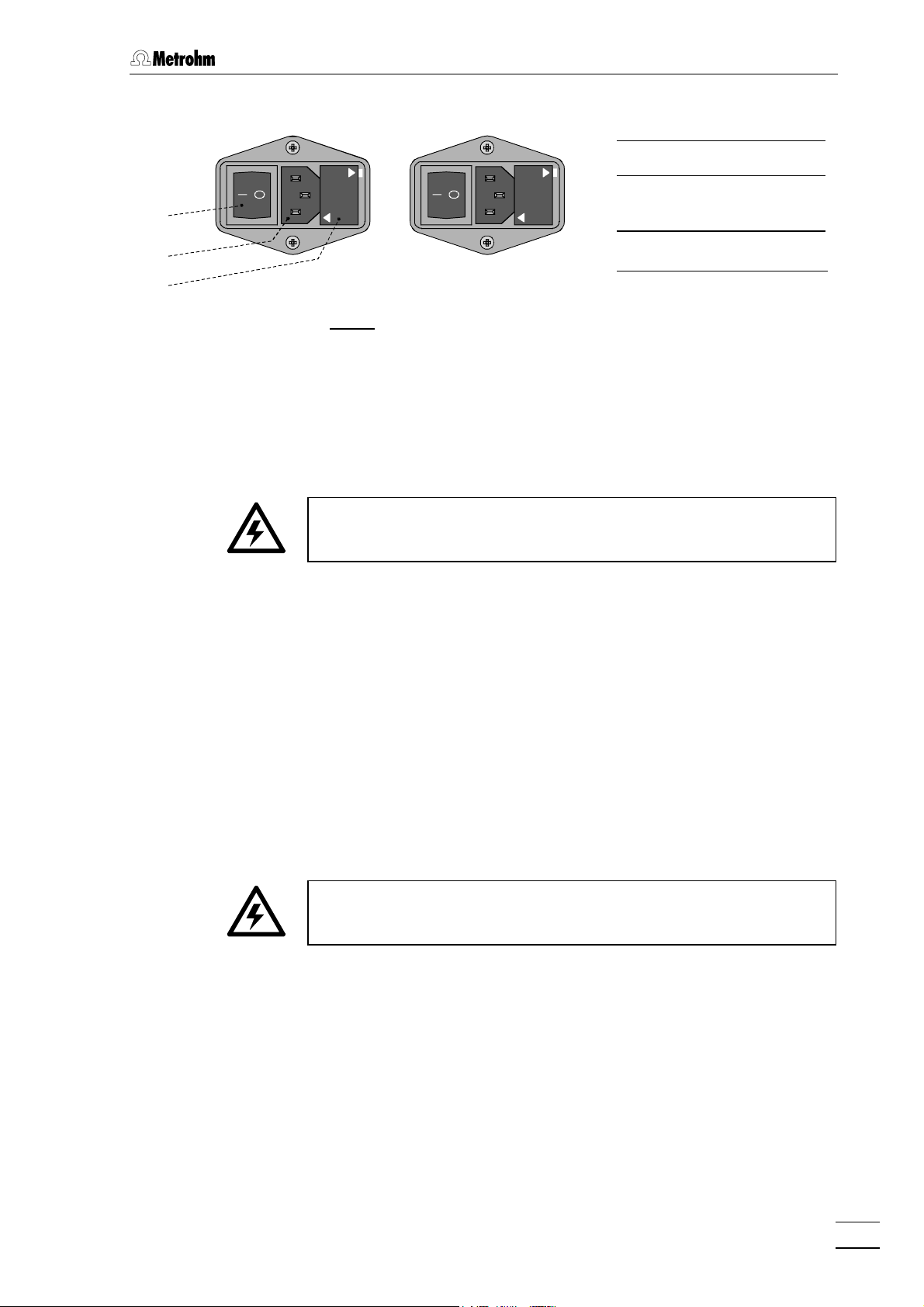
100 – 120 V
2626
2525
2424
2.2.2 Fuses
220 – 240 V
220
-
- 240 V
-
- 120 V
100
100
-
- 120 V
-
- 240 V
220
2424 Fuse holder
2525 Mains connection
plug
2626 Mains switch
Fig. 3: Setting the mains voltage
One of the two fuses 0.5 A/slow-blow for 100…120 V or 0.25 A/slowblow for 220…240 V is installed in fuse holder 2424 of the 766 IC Sample
Processor as standard.
Ensure that the instrument is never put into operation with fuses of
another type, otherwise there is danger of fire!
For checking or changing fuses, proceed as described in section 2.2.1.
2.2.3 Mains cable and mains connection
Mains cable
The instrument is supplied with one of three mains cables
• 6.2122.020 with plug SEV 12 (Switzerland, …)
• 6.2122.040 with plug CEE(7), VII (Germany, …)
• 6.2133.070 with plug NEMA 5-15 (USA, …)
which are three-cored and fitted with a plug with an earthing pin. If a
different plug has to be fitted, the yellow/green lead (IEC standard)
must be connected to protective earth (protection class 1).
Any break in the earthing inside or outside the instrument can make it
a hazard!
Mains connection
Plug the mains cable into mains connection plug 2525 of the 766 IC
Sample Processor (see Fig. 3).
2.2.4 Switching the instrument on/off
The 766 IC Sample Processor is switched on and off using mains
switch 2626.
766 IC Sample Processor
11
Page 17
2 Installation
2.3 Attaching the accessories
For attaching the accessories at the 766 IC Sample Processor, proceed in the order described below.
2.3.1 Connecting the swing head
Plug in the branch plug of the connection cable 2121 permanently at-
tached to the swing head into the remote connection socket at the 766
IC Sample Processor and screw it onto this connection using a screwdriver (see Fig. 1).
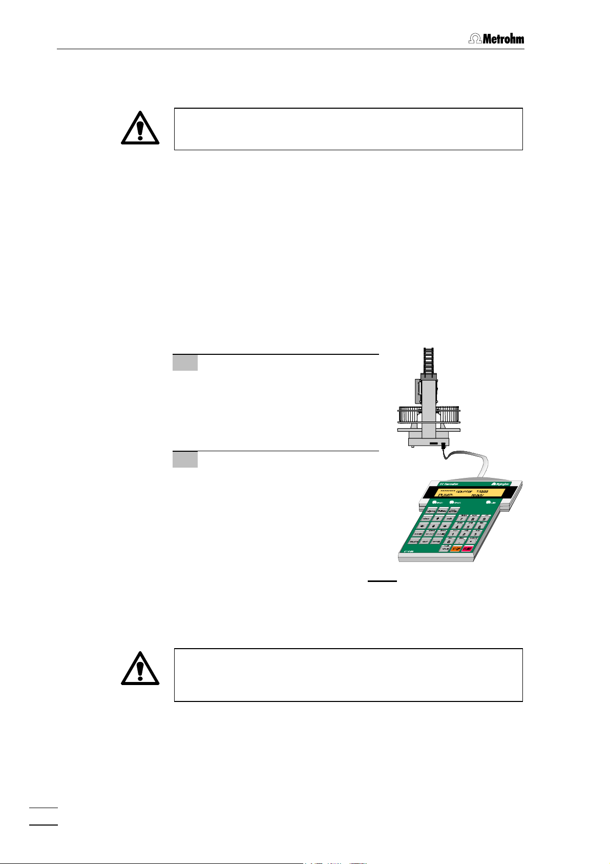
2.3.2 Connecting the keyboard
Connecting the keyboard
1
Connect the 6.2142.010 keyboard
to the keyboard connection 3131
"Keyboard". For disconnection,
press the plug together slightly on
both sides.
Switch on instrument
2
Switch on the 766 IC Sample
Processor with mains switch 2626.
The keyboard display lights up.
The instrument is initialized and
the lift is raised completely.
2.3.3 Installing the plug cover
Fig. 4: Keyboard connection
12
To prevent any contamination of the mains and remote connection by
spilled solvents or chemicals, the 6.2752.010 plug cover must always
be installed when operating the 766 IC Sample Processor !
Install the plug cover 2323 in the corresponding guide groove above
mains connection plug 2525 and remote connection 2222 (see Fig. 1 and
Fig. 2).
766 IC Sample Processor
Page 18
2.3.4 Installing the splash protection
To avoid any danger of injury by the needle, the 6.2751.040 splash
protection must always be installed when operating the 766 IC Sample Processor!
Remove holding screws
1
Remove the holding screws 2929 and the washer mounted on the
screw threads 1111 at tower 1919 using the 6.2621.100 Allen key.
Remove protective film from splash protection
2
Remove the plastic film glued on both sides of the splash protection 11.
Install splash protection
3
Attach splash protection 11 onto the screw threads 1111 at the
tower 1919 and fix it with the holding screws 2929 and the washer
using the 6.2621.100 Allen key.
2.3 Attaching the accessories
11 Splash protection
(6.2751.040)
2929 Holding screws
2.3.5 Installing the needle
Remove PEEK compression fitting 5
1
Remove PEEK compression fitting 55 screwed onto the needle
holder 44.
Insert needle
2
Insert needle 22 (6.2624.000 steel needle or 6.1835.000 PEEK
needle) completely into the opening of the needle holder 44.
2929
11
2929
Fig. 5: Installing the splash protection
766 IC Sample Processor
Fix needle
3
Tighten compression fitting 55 in needle holder 44 by hand (never
use tools!).
13
Page 19
2 Installation
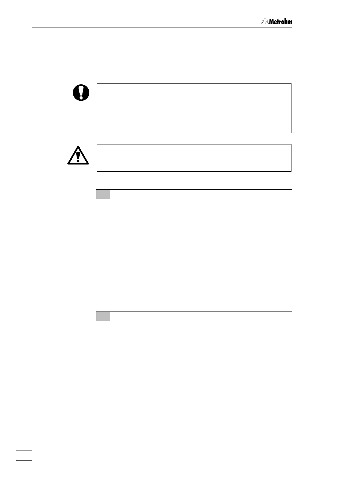
22 Steel needle (6.2624.000) or
PEEK needle (6.1835.000)
88
77
44 Needle holder
66
55 PEEK compression fitting
(4.766.4030)
66 PEEK compression fitting
(6.2744.010)
77 Swing head
88 PEEK capillary (6.1831.050)
If you are using the 6.1835.000 PEEK needle, the sample tubes may
not be sealed with caps because they cannot be pierced by the PEEK
needle and the needle may be damaged thereby.
55
44
22
Fig. 6: Needle installation
2.3.6 Placing the sample rack
Place sample rack
1
Place sample rack 2727 on the
turntable of the 766 IC Sample
Processor acc. to Fig. 7.
Read magnetic code
2
Press <RESET> to move the
rack to the home position, in
which the magnetic code can
be read (details see section
4.5).
2.3.7 Adjusting the sample rack
If a new sample rack is placed on the 766 IC Sample Processor for the
first time, it must be adjusted on a rack position in the middle row
(example: position 37) as follows:
Fig. 7: Sample rack placing
14
Place sample rack
1
Place empty sample rack 2727 on the 766 IC Sample Processor
and press <RESET> (see section 2.3.6).
766 IC Sample Processor
Page 20
2.3 Attaching the accessories
22 Steel neddle
(6.2624.000) or PEEK
needle (6.1835.000)
2727 Sample rack
(6.2041.430)
3232 Adjusting position 37
3333 Adjusting screw
Move to adjusting position
2
Press <MOVE>, enter number '37' and confirm with
<ENTER>. Sample rack and swing head are turned until needle
22 is above the adjusting position 3232 (position 37: first opening of
the middle row).
Check needle position
3
• Press <ê> until the needle 22 is ca. 1 cm above the upper
level of the sample rack 2727.
• Check needle position: If the needle 2 cannot be lowered
unhindered through the upper hole of the adjusting position
32, continue directly with point 4.
• Continue lowering the needle by pressing <ê> until the
needle 22 is ca. 1 cm above the lower level of the sample rack
2727.
• Check needle position: If the needle 2 cannot be lowered
unhindered through the lower hole of the adjusting position
32, continue directly with point 4.
• Lower needle completely by pressing <ê>.
• Check needle position: If the needle 22 is in the middle of the
lower hole, the sample rack must not be adjusted (continue in
this case with point 5).
22
3232
3333
2727
Fig. 8: Adjusting the sample rack
766 IC Sample Processor
Adjust sample rack
4
• Loosen the three adjusting screws 3333 on the lower level of the
sample rack using the 6.2621.100 Allen key
• Carefully turn the two upper levels of the sample rack 2727 by
hand until the lowered needle 22 is exactly in the middle of the
lower hole at the adjusting position 3232.
• Tighten the adjusting screws 3333.
Move to rest position
5
Press <RESET> to move the sample rack to the rest position.
15
Page 21
2 Installation
2.3.8 Tubing connections 766 – 733
For transferring the sample from the 766 IC Sample Processor to the
injection valve of the 733 IC Separation Center the following tubing
connections must be made:
Pump tubings are consumable material with a lifetime which depends
on the contact pressure (see section 6.3.3). This is why the tubing
cartridges should be raised completely by loosening snap-action lever
1717 on the right-hand side if the pump is to remain switched off for a
considerable length of time (the set contact pressure remains unchanged).
The 6.1826.0X0 pump tubing is made of PVC and must not be used
for rinsing with solutions which contain acetone. In such cases, rinse
with different pump tubing or a different pump.
Install pump tubing
1
• Release tubing cartridge 1313 from holding clamp 1616 by
pressing down snap-action lever 1717 and remove from
mounting pin 1212 on the 766 IC Sample Processor (see Fig.
1).
• Press contact pressure lever 1515 on the tubing cartridge down
as far as it will go.
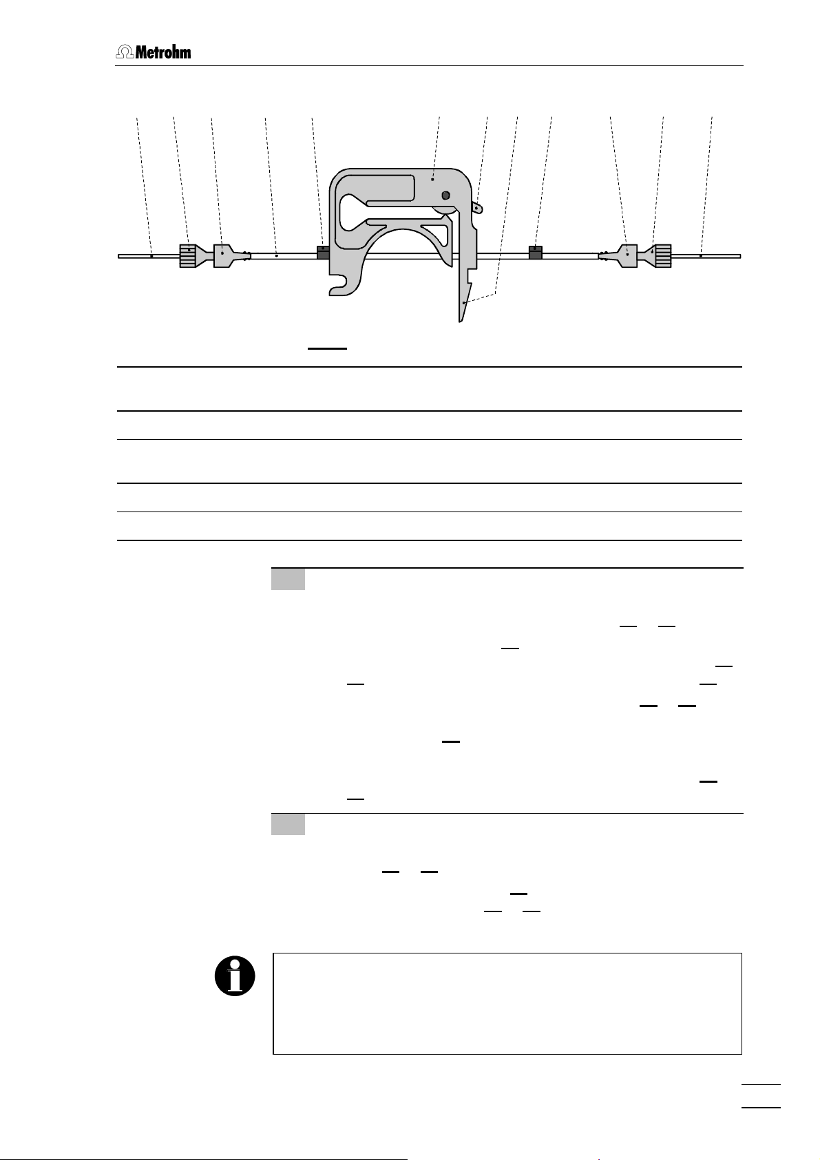
• Insert pump tubing 1010 in the tubing cartridge 1313 as shown in
Fig. 9. The black-black stopper 3636 must click into the corre-
sponding holder on the left-hand side of the tubing cartridge.
• Place the tubing cartridge 1313 on mounting pin 1212 and press
down on the right-hand side until snap-action lever 1717 clicks
into position on holding clamp 1616. Take care that no kinks are
formed in the pump tubing.
Connection needle – pump tubing
2
• Mount the PEEK compression fitting 66 on one end of the
PEEK capillary 88 and the PEEK compression fitting 3434 on the
other end.
• Screw the PEEK capillary 88 with the PEEK compression fitting
66 on to the PEEK compression fitting 55 already mounted on
needle holder 44 (see Fig. 6).
• Insert PEEK capillary 88 into the guide chain 99 (see Fig. 1 and
section 2.3.8).
• Screw a coupling 3535 on to the PEEK compression fitting 3434 at
the other end of PEEK capillary 88.
• Push coupling 3535 on to the inlet end of the pump tubing 1010
(see Fig. 6).
16
766 IC Sample Processor
Page 22
88 3535 1010 3636 1313 1515 3636 3535 18181717 343466
2.3 Attaching the accessories
Fig. 9: Installing the pump tubing
66 PEEK compression fitting
1717 Snap-action lever
(6.2744.010)
88 PEEK capillary (6.1831.050) 1818 PEEK capillary (6.1831.060)
1010 Pump tubing (6.1826.040) 3434 PEEK compression fitting
(6.2744.010)
1313 Tubing cartridge (6.2755.000) 3535 Coupling (6.2744.030)
1515 Contact pressure lever 3636 Stopper (black-black)
Connection pump tubing – injection valve
3
• At the 733 IC Separation Center, loosen the rotary nipple
screwed onto the interior side of connection 2222 or 2828.
• Take PTFE suction tubing 8484 (see Fig. 14 and Fig. 15 of the
732/733 Instructions for Use) completely out of connection 2222
or 2828 and unscrew from connection "1" of injection valve 6666.
• Pull the PEEK capillary 1818 through the opening 2222 or 2828 of
the 733 IC Separation Center and screw onto connection "1"
of injection valve 6666 using a 6.2744.010 PEEK compression
fitting.
• Retighten rotary nipple on the interior side of connection 2222
or 2828 to fix the capillary 1818.
766 IC Sample Processor
Tubing connection injection valve – waste
4
• Insert 6.2744.020 coupling (from 733 accessories) into con-
nection 2121 or 2727 of the 733 IC Separation Center.
• Screw PTFE suction tubing 8484 onto the 6.2744.020 coupling
attached to connection 2121 or 2727 and lead it into the waste
container.
In the case of the 733.0020 IC Separation Center with two injection
valves, it is possible to fill both sample loops from the same 766 IC
Sample Processor. For this, connection "1" of valve A (outlet of the
sample loop) must be connected to connection "2" of valve B (inlet of
the sample loop) using a 6.1803.040 PEEK capillary (15 cm).
17
Page 23
2 Installation
2.3.9 Tubing connections 766 – 754
If the 766 IC Sample Processor is used for an IC system with sample
dialysis (see section 2.4.6), the peristaltic pump at the 754 Dialysis Unit
is used for sample conveying instead of the pump at the 766 IC Sample
Processor. The tubing connections between the 754 Dialysis Unit 754
and the 733 IC Separation Center 733 have to be made as shown in
Fig. 8 of the 754 Instruction for Use. The only change concerns the inlet
of the sample, which is installed as follows:
Install a PEEK compression fitting 6.2744.010 on the inlet end of the
PTFE tubing 2626 (6.1803.030, see Fig. 8 of the 754 Instruction for Use)
connected to the 754 Dialysis Unit and screw it on the PEEK compression fitting 55 (see Fig. 6).
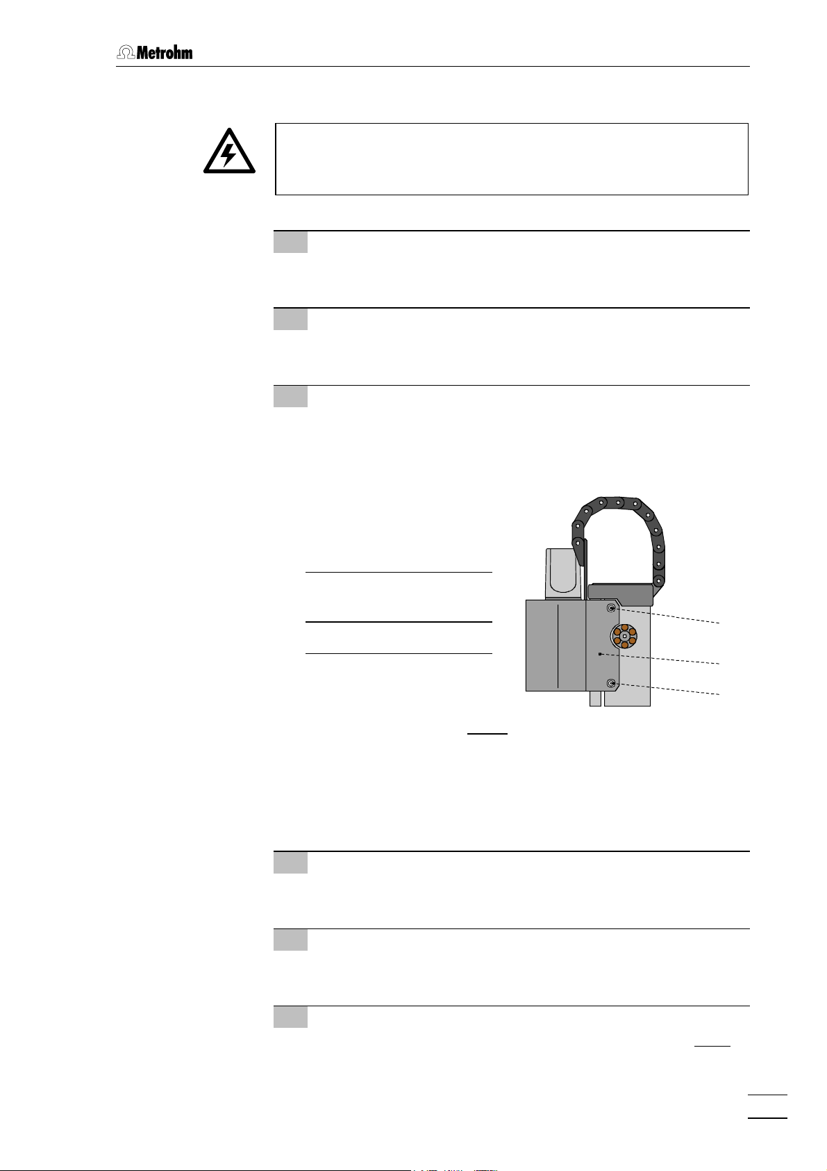
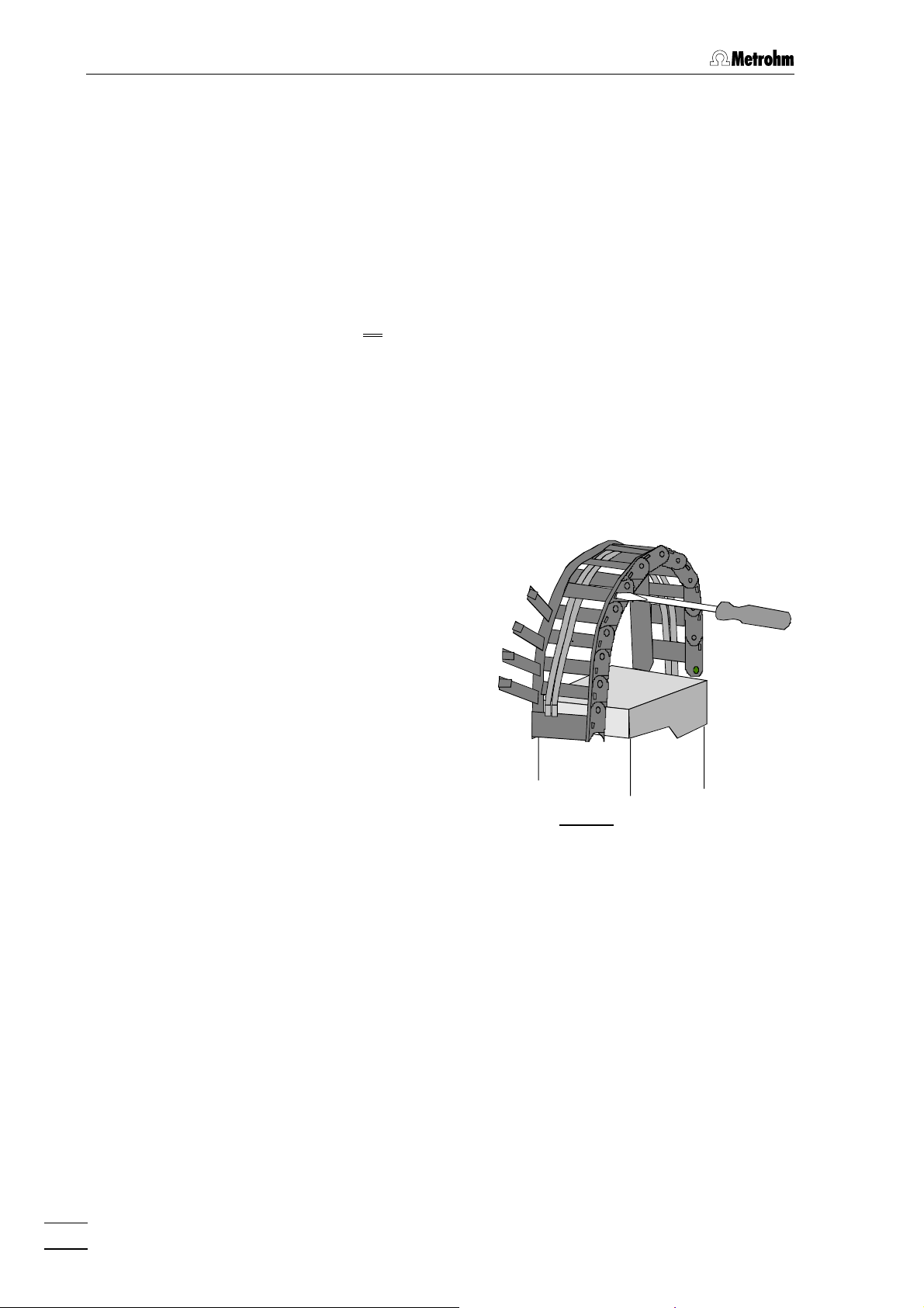
2.3.10 Fixing tubing and cables
In order to fix tubing or cables in
the guide chain 99 any chain link
may be opened with a screw
driver or another appropriate tool.
Fig. 10: Opening chain links
18
766 IC Sample Processor
Page 24
2.4 Connection of devices to the remote interface
732/1 Remote
2.4 Connection of devices to the
remote interface
2.4.1 General information on remote interface
The branch plug of cable 2121 leading from the swing head (see Fig. 1) is
plugged into the 25 pin remote interface (see section 2.3.1). Any external devices can be connected to remote connection 2222 of this branch
plug. The 766 IC Sample Processor can be remote controlled via the 8
input lines, the 14 output lines can be used to control external devices.
Before an external device is connected to remote connection 2222, the
766 IC Sample Processor must always be switched off using mains
switch 2626!
The pin assignment of the remote interface, its functions, the electrical
requirements and conditions are described in section 5.1.
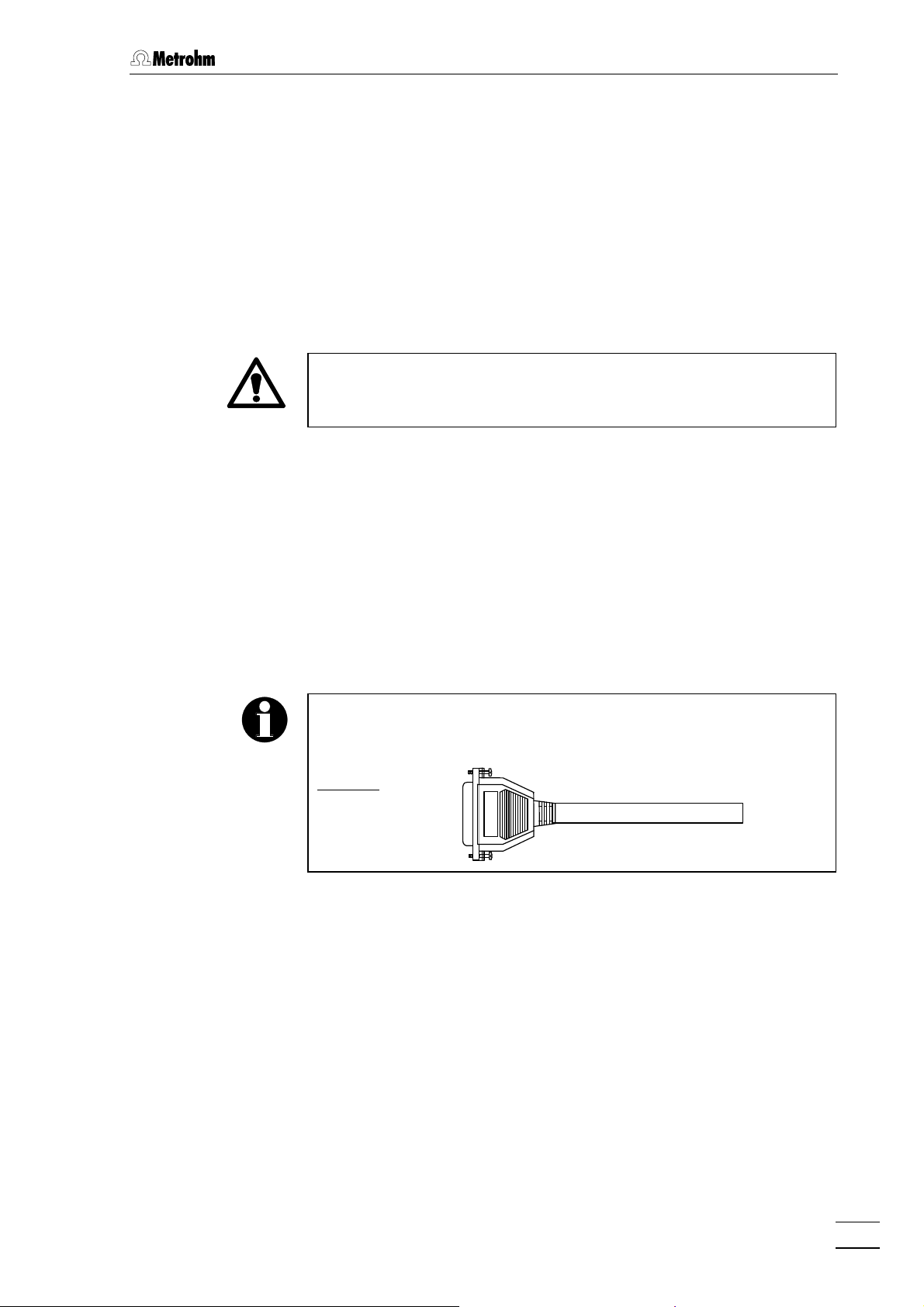
2.4.2 Connection cables
Connecting peripheral instruments to the 766 IC Sample Processor requires Metrohm cables. Otherwise a safe data transmission may not be
guaranteed.
Metrohm cables are labeled with the type of the instrument which they
may be connected with and optionally with the particular socket. Mind
the cable ends.
Example:
766 IC Sample Processor
19
Page 25
2 Installation
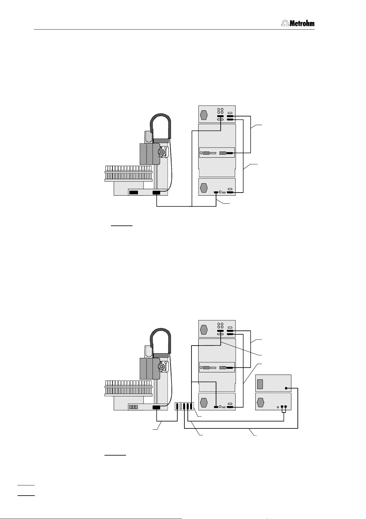
2.4.3 IC system without suppression
The 766 IC Sample Processor is connected to an IC system without
suppression consisting of 732 IC Detector, 733 IC Separation Center
and 709 IC Pump as shown in Fig. 11 using the 6.2141.110 cable. With
this interconnection the standard methods 'PC', 'PC Seg', 'SP' and
'SP Seg' can be used (see section 4.6).
732
733
6.2125.060 cable
709
766
6.2141.110 cable
Fig. 11: Interconnection with IC system without suppression
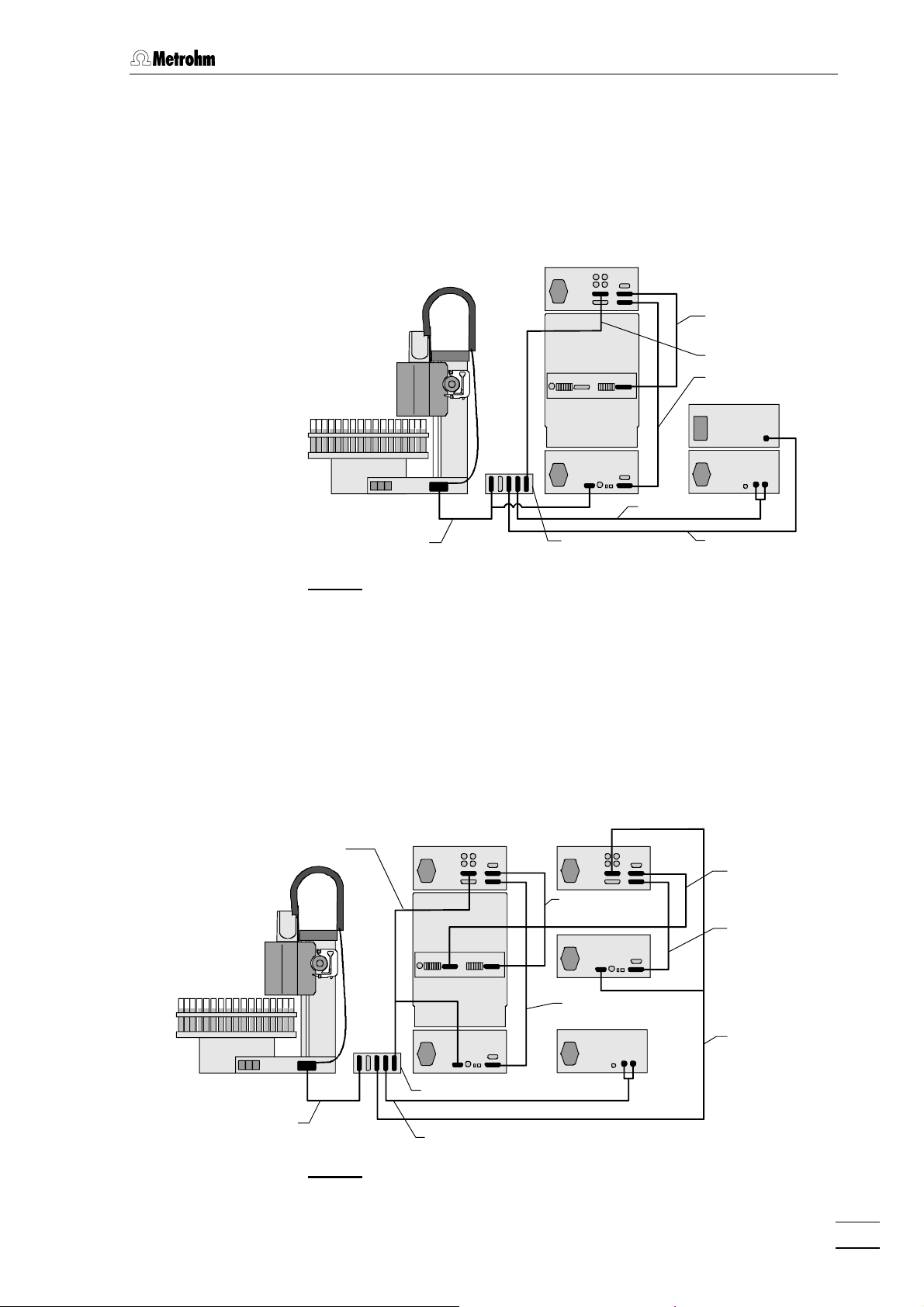
2.4.4 IC system with suppression with 766 as "Master"
The 766 IC Sample Processor is connected to an IC system with suppression consisting of 732 IC Detector, 733 IC Separation Center, 709
IC Pump and either 752 Pump Unit or 753 Suppressor Module as
shown in Fig. 12 using the 6.2125.120 adaptor. With this interconnection, in which the 766 IC Sample Processor is the "Master", the standard
methods 'SP' and 'SP Seg' can be used (see section 4.6).
6.2125.090 cable
20
732
733
709
766
6.2125.120 adaptor
6.2125.090 cable
6.2143.210 cable
6.2125.090 cable
6.2141.110 cable
6.2125.060 cable
752
753
6.2143.200 cable
Fig. 12: Interconnection with IC system with suppression with
766 as "Master"
766 IC Sample Processor
Page 26
2.4 Connection of devices to the remote interface
2.4.5 IC system with suppression with PC as "Master"
The 766 IC Sample Processor is connected to an IC system with suppression consisting of 732 IC Detector, 733 IC Separation Center, 709
IC Pump and either 752 Pump Unit or 753 Suppressor Module as
shown in Fig. 13 using the 6.2125.120 adaptor. With this interconnection, in which the PC is the "Master", the standard methods 'PC',
'PC Seg' and 'Preconc' can be used (see section 4.6).
732
733
709
766
6.2141.110 cable
6.2125.120 adaptor
Fig. 13: Interconnection with IC system with suppression with
PC as "Master"
2.4.6 IC system for simultaneous anion/cation
determination
The 766 IC Sample Processor is connected to an IC system for simultaneous determination of anions and cations consisting of two 732 IC
Detectors, the 733 IC Separation Center, two 709 IC Pumps and (if
suppression is used) the 753 Suppressor Module as shown in Fig. 14
using the 6.2125.120 adaptor. With this interconnection the standard
methods 'AnCat' and 'AnCatSeg' can be used (see section 4.6).
6.2125.090 cable
6.2125.090 cable
6.2125.060 cable
752
753
6.2143.210 cable
6.2143.200 cable
6.2141.110 cable
766
6.2125.090 cable
766 IC Sample Processor
732/1
733
709/1
6.2125.120 adaptor
6.2143.210 cable
732/2
6.2125.090 cable
709/2
6.2125.060 cable
753
Fig. 14: Interconnection for anion/cation system
6.2125.090 cable
6.2125.060 cable
6.2141.120 cable
21
Page 27
2 Installation
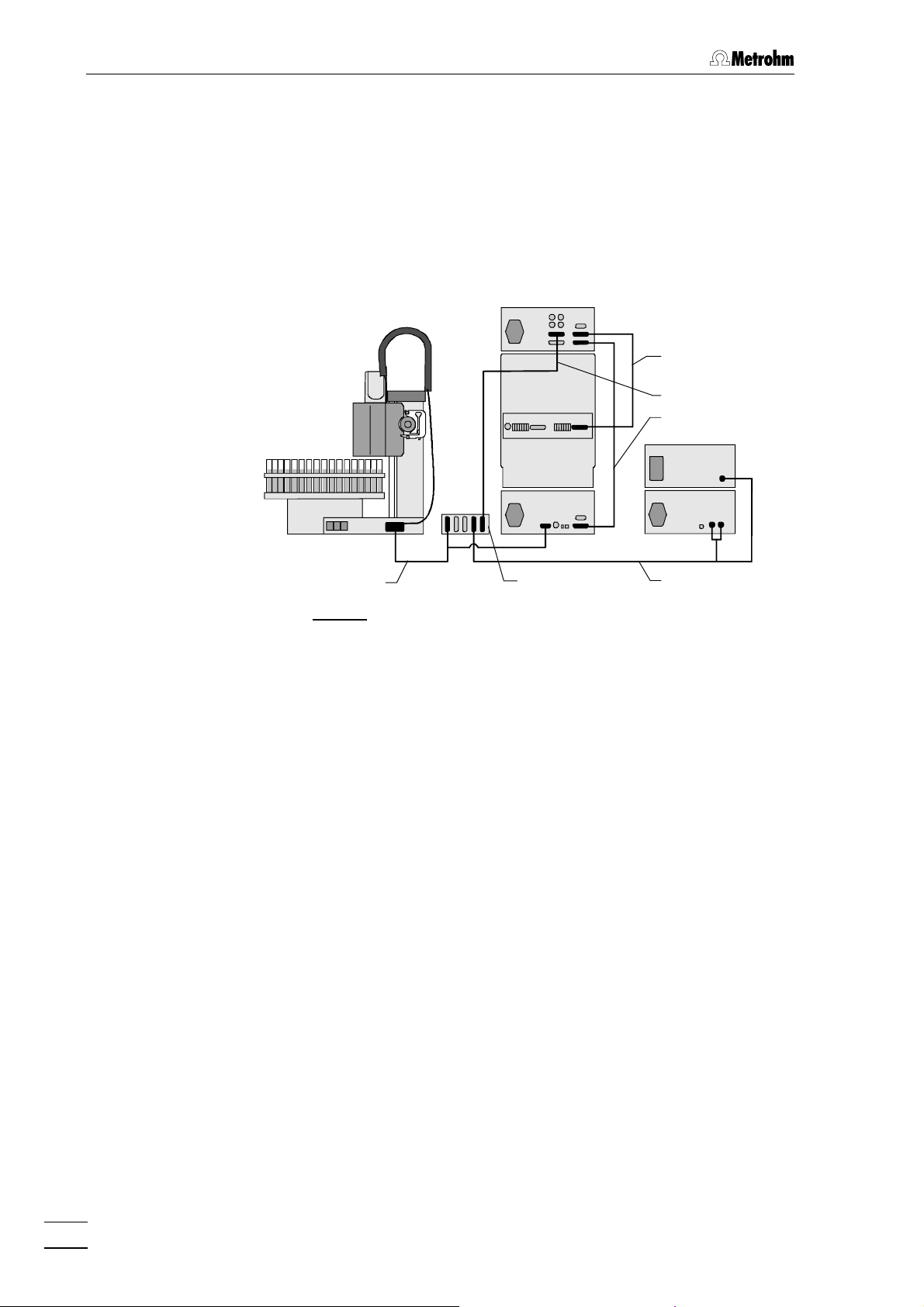
2.4.7 IC system with sample dialysis
The 766 IC Sample Processor is connected to an IC system with sample dialysis consisting of 732 IC Detector, 733 IC Separation Center,
709 IC Pump, 754 Dialysis Unit and (if suppression is used) the 753
Suppressor Module as shown in Fig. 15 using the 6.2125.120 adaptor.
With this interconnection the standard method 'Dialysis' can be used
(see section 4.6). If no suppression is used, the 754 Dialysis Unit can
be connected to the 6.2125.120 adaptor using the 6.2143.200 cable.
732
733
709
766
6.2125.120 adaptor
6.2125.090 cable
6.2125.090 cable
6.2125.060 cable
754
753
6.2143.220 cable6.2141.110 cable
Fig. 15: Interconnection with IC system with dialysis
22
766 IC Sample Processor
Page 28
2.5 Connection of devices to the RS232 interface
6.2125.060 cable
Printer cables, see section 2.5.2
2.5 Connection of devices to the RS232
interface
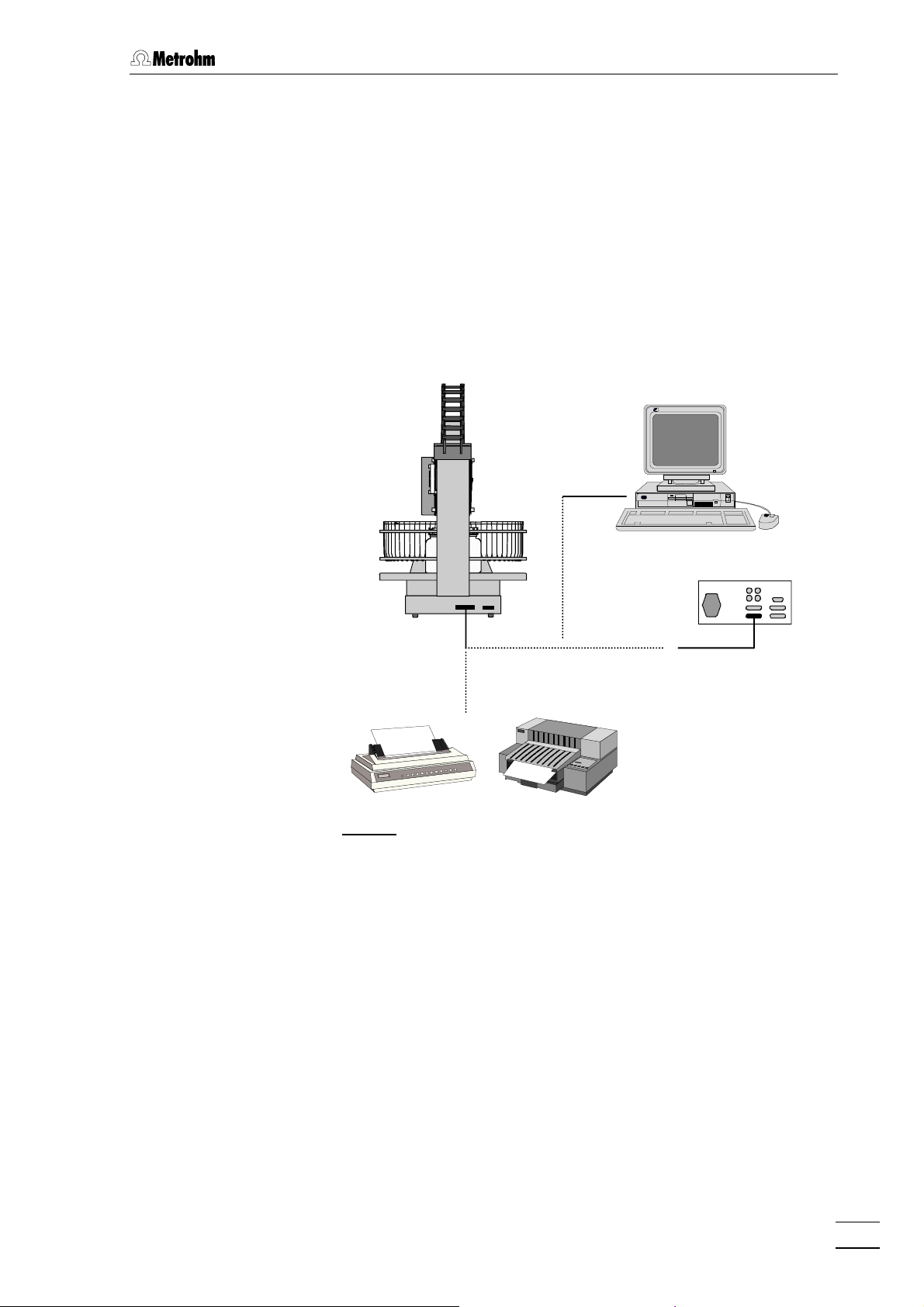
2.5.1 General information on RS232 interface
Many different instruments may be connected via the serial RS232 interface 3232. In addition to all Metrohm instruments that support the
Metrohm remote control language (see section 5.2) any printer with serial interface (or parallel interface and parallel/serial converter) or a personal computer (PC) may be connected. Any other measuring instrument may be controlled via RS232 interface, as long as it supports
serial data transmission.
766
732
Fig. 16: Connection possibilities for the RS232 interface
In order to guarantee safe data transmission, it is important to set the
same RS232 interface parameters correctly for both instruments connected (see section 2.5.2).
Control commands (examples)
CTL:RS &M;$G starts a Metrohm instrument
CTL:RS &M;$S stops a Metrohm instrument
PRINT: config prints a configuration report to
a printer or PC
766 IC Sample Processor
Scanning input data (example):
SCN:RS : *R" waiting for readiness of a Metrohm
instrument
23
Page 29
2 Installation
2.5.2 Connection of a printer
Printers with the following printer drivers may be connected:
IBM IBM Proprinter and printers with IBM emulation
Epson Epson printers and printers with Epson emulation
Seiko Seiko printers DPU-411 and DPU-414
Citizen Citizen printer IDP562-RS
HP HP printers and compatibles with HP PCL3 emulation
If you connect other printers, ensure that these emulate a printer mode
supported by the 766 IC Sample Processor.
Most printers with a serial interface are connected using the 6.2125.050
Cable. Printers with a parallel interface need a serial/parallel converter
(e.g. 2.145.0300) and the 6.2125.020 Cable.
Before connecting a printer to the RS232 interface, switch off the 766
IC Sample Processor !
The interface parameters are set in the configuration submenu ">RS232
settings".
The following table provides information on a few selected printers.
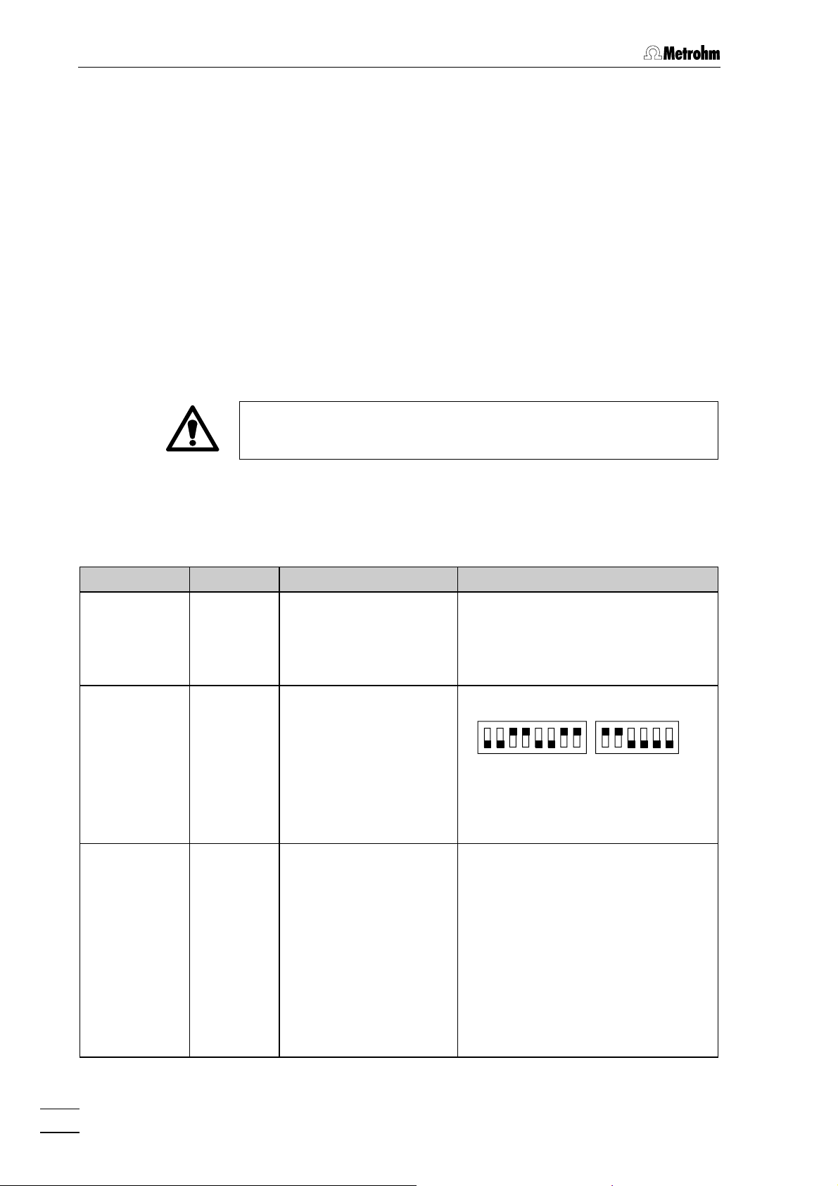
Printer Cable RS232 settings Settings on printer
IBM Proprinter 6.2125.050
Seiko
DPU-411
Seiko
DPU-414
6.2125.020 baud rate: 9600
6.2125.130 baud rate: 9600
baud rate: 9600
data bit: 8
stop bit: 1
parity: none
handshake: Hws
character set: IBM
data bit: 8
stop bit: 1
parity: none
handshake: Hws
character set: Seiko
data bit: 8
stop bit: 1
parity: none
handshake: Hws
character set: Seiko
see printer manual
Settings of the DIP switches:
DIP01 DIP02
on
off
1 2 3 4 5 6 7 8 1 2 3 4 5 6
The switchable 7-bit ASCII character set of
the printer will be automatically set by the
732 IC Detector to the national character
sets in accordance with the set dialog
language.
Settings of the DIP switches:
Dip SW-1Dip SW-1 Dip SW-2Dip SW-2 Dip SW-3Dip SW-3
11 OFF ON ON
22 ON OFF ON
33 ON ON ON
44 OFF ON ON
55 ON ON OFF
66 OFF ON ON
77 ON OFF ON
88 ON OFF ON
The switchable 7-bit ASCII character set of
the printer will be automatically set by the
732 IC Detector to the national character
sets in accordance with the set dialog
language.
24
766 IC Sample Processor
Page 30
2.5 Connection of devices to the RS232 interface
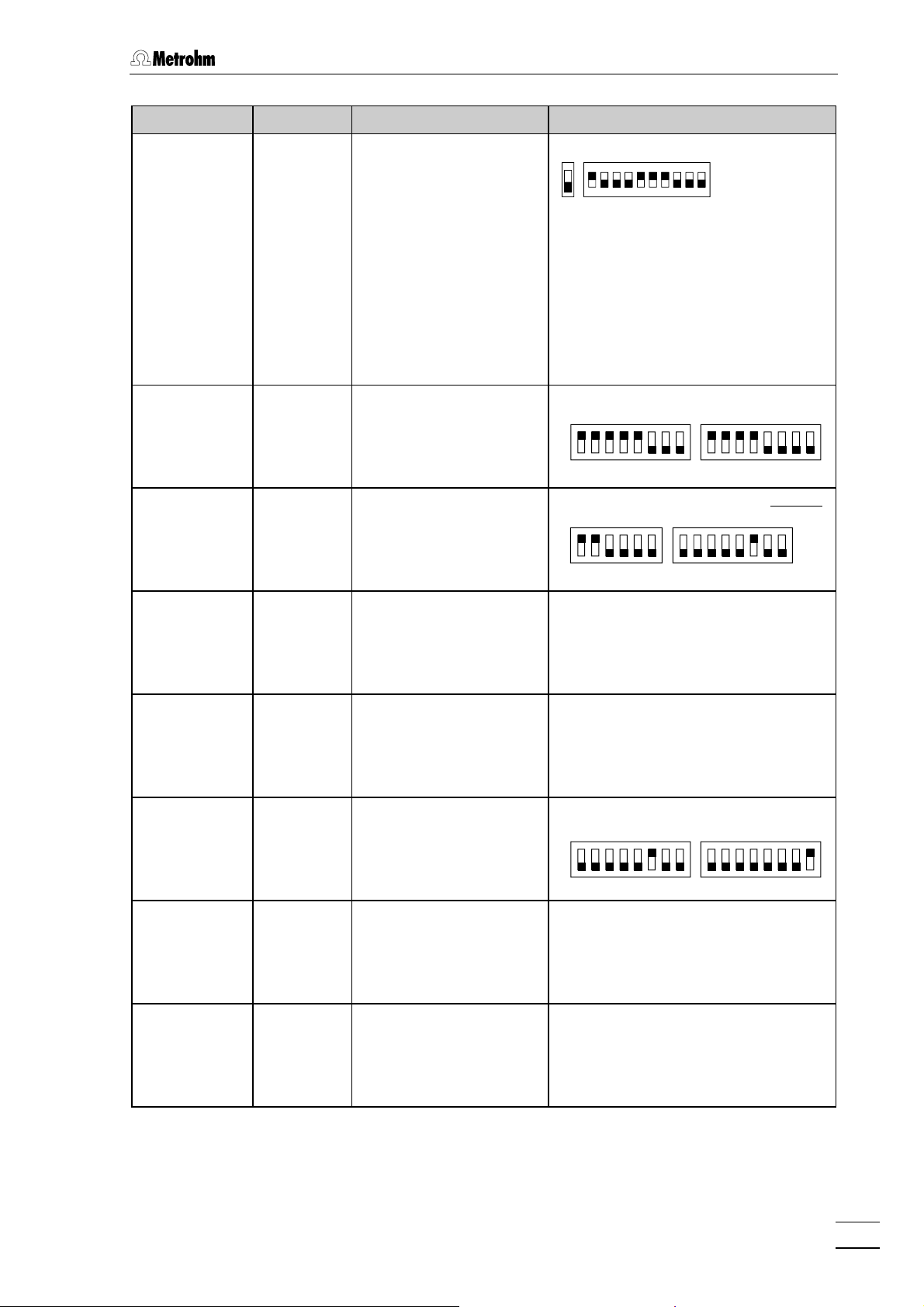
Printer Cable RS232 settings Settings on printer
Citizen
IDP562-RS
6.2125.050 baud rate: 9600
data bit: 8
stop bit: 1
parity: none
handshake: Hws
character set:Citizen
Epson
with 6-pin round
connector
6.2125.040 baud rate: 9600
data bit: 8
stop bit: 1
parity: none
handshake: Hws
character set: Epson
Epson
with additional
serial interface
#8148
6.2125.050 baud rate: 9600
data bit: 8
stop bit: 1
parity: none
handshake: Hws
character set: Epson
Epson LX-300 6.2125.050 baud rate: 9600
data bit: 8
stop bit: 1
parity: none
handshake: Hws
character set: Epson
Epson and
Canon printers
with parallel
interface
HP Deskjet
with serial
interface
HP Laserjet
with serial
interface
6.2125.020
+
2.145.0300
serial/
parallel
converter
6.2125.050
or adaptor
cable 25-pin
neg./9-pin
pos. (e.g. HP
C2933A)
Adaptor
cable 25-pin
neg./9-pin
pos. (e.g. HP
C2933A)
baud rate: 9600
data bit: 8
stop bit: 1
parity: none
handshake: Hws
character set: Epson
baud rate: 9600
data bit: 8
stop bit: 1
parity: none
handshake: Hws
character set: HP
baud rate: 9600
data bit: 8
stop bit: 1
parity: none
handshake: Hws
character set: HP
HP Deskjet/
Laserjet
with parallel
6.2125.020
+
2.145.0300
serial/
parallel
converter
baud rate: 9600
data bit: 8
stop bit: 1
parity: none
handshake: Hws
character set: HP
Settings of the DIP switches:
ON
1 2 3 4 5 6 7 8 9
SSW1
The switchable 7-bit ASCII character set of
the printer can be changed to the national
character sets only by setting Dip switch 4
and 5:
44 55 Character setCharacter set
OFF OFF USA
ON ON Great Britain
ON OFF France
OFF ON Germany
Spanish does not have its own character set
(it is best to select French).
Settings of the DIP switches:
SW1 SW2
on
off
1 2 3 4 5 6 7 8 1 2 3 4 5 6 7 8
Settings of the DIP switches on the interface:
SW1 SW2
on
off
1 2 3 4 5 6 7 81 2 3 4 5 6
see printer manual
see printer manual
Settings of the DIP switches:
A B
on
off
1 2 3 4 5 6 7 8 1 2 3 4 5 6 7 8
see printer manual
see printer manual
10
766 IC Sample Processor
25
Page 31

2 Installation
26
766 IC Sample Processor
Page 32

3 Operating tutorial
In order to become acquainted with the 766 IC Sample Processor and its
mode of operation, it is helpful to work through the short Operating
Tutorial. The basic operating steps that are required to prepare the first
sample series and run it with a given method are described here.
For further explanations of the operation, please refer to section 4, which
describes the functions of the individual keys and the programming in
detail.
3.1 Prerequisites / Preparations
3.1 Prerequisites / Preparations
• It is assumed that the 766 IC Sample Processor is fully installed (see
section 2). Don’t forget to mount the splash protection and the plug
cover.
• Connect a 732 IC Detector at the remote connection 2222 (see section
2.4).
• Choose a simple IC method that you have saved in the 732 IC De-
tector or create a new simple method.
• The <é> and <ê> keys can be used to move the lift up or down.
RESET
CLEAR
ENDSEQ
>
*
• Install the 6.2041.430 sample rack. Press <RESET> or
<ENDSEQ> + <ENTER>. The 766 IC Sample Processor is initialized in this way with the lift and rack placed in the rest position. In
this position the magnetic rack code can be read so that the internally stored rack data (position table, etc.) can be loaded.
This should be done after every rack change.
• Insert some sample tubes into the sample rack, beginning with
position 1. Using the keys <ç> and <è> the rack can be turned
for this purpose.
766 IC Sample Processor
27
Page 33

3 Operating tutorial
3.2 Configuration
• The dialog language can be set in the configuration menu. Press
CONFIG
ENTER
<CONFIG>
• and then <ENTER>.
configuration
>auxiliaries
>auxiliaries
dialog: english
TOWER
SELECT
4 × <ê>
<ENTER>
• This menu item has a colon, indicating that here the parameters can
be selected from a list. Press <SELECT> several times in order to
view the various selections and get used to this type of dialog.
>auxiliaries
dialog: deutsch
• With <ENTER> you can accept the suggestion 'dialog: eng-
lish'.
>auxiliaries
display contrast: 3
• By pressing <ê> 4 times you reach the menu selection 'max. lift
way'.
>auxiliaries
max. lift way 125 mm
• Here the lowest allowable lift position for automatic and manual
operation can be set. For the 6.2041.430 sample rack with
6.2743.050 sample tubes, this limit value of 125 mm should not be
changed. Accept the value by pressing <ENTER>.
28
QUIT
or
STOP
configuration
>rack definitions
• In order to put the 766 IC Sample Processor back into the initial
position, press <QUIT> or <STOP>.
******** counter 0/127
PUMP- ready
• In the normal state, the method name and the sample counter
reading are displayed in the first line. The second line serves as
status line which displays the pump status and the changer status.
766 IC Sample Processor
Page 34

3.3 Rack configuration
RESET
CLEAR
• At the end of this basic configuration the 766 IC Sample Processor
must be turned off and on again or re-initialized by pressing
<RESET> to make the latest settings effective.
• All data entered up to this point however, are retained. The same is
true for any methods that may have been saved.
3.3 Rack configuration
• Using the keys <é> and <ê> you can run the lift to the desired
work position for the needle.
CONFIG
<ê>
<ENTER>
<ENTER>
<ê>
RESET
CLEAR
• Now open the configuration menu with <CONFIG> and move the
cursor key <ê>, until you reach the submenu '>rack defini-
tions'. Press <ENTER> to open this submenu where you can de-
fine the rack configuration.
>rack definitions
rack number 2
• The rack number of the engaged rack will be displayed as soon as
the sample rack has been correctly identified. By confirming with
<ENTER> you access the rack data. (By entering another rack
number you can also edit the data of a sample rack that is not engaged.)
• You can skip the first entries (code and rack type) with the cursor
key <ê>. Now you can enter the work position of the needle.
>rack definitions 2
work position 125 mm
• Because you have already positioned the needle at the desired
height, you can accept the current lift position directly by pressing
<CLEAR>. Of course the work position can be entered manually or
the value that has automatically been accepted can be modified
later. Lift positions are given in millimeters (0…125 mm), measured
from the uppermost limit (rest position) of the lift. Consider during
the input of the working position that with sample tubes sealed with
PE caps the work position must be set to 125 mm, since otherwise a
vacuum can develop in the sample tube and the sample will not be
aspirated correctly.
766 IC Sample Processor
29
Page 35

3 Operating tutorial
>rack definitions 2
work position 71 mm
<ENTER>
<ENTER>
<ENTER>
• In any case don’t forget to confirm the value with <ENTER>.
>rack definitions 2
rinse position 125 mm
• The next menu item 'rinse position' defines the height at which
the lift must be when the needle is rinsed. As for the work position,
the value here can also be entered manually or automatically accepted. For the latter, the configuration menu must be exited by
pressing <QUIT> twice and the lift newly positioned.
>rack definitions 2
rinse position 105 mm
>rack definitions 2
shift position 0 mm
• The menu item 'shift position' defines the height of the needle
when the sample rack is rotated. For the 766 IC Sample Processor
this height is set to 0 mm and cannot be changed.
• Press <ENTER>.
<ENTER>
<ENTER>
<ENTER>
STOP
>rack definitions 2
special position 0 mm
• The 'special position' defines a further height of the lift. For the
entry proceed as for the work position.
>rack definitions 2
special position 55 mm
• The final entry in the rack configuration is the definition of the posi-
tion of the special beakers.
>rack definitions 2
>>special positions
• In the submenu '>>special positions' enter the positions at which
you have placed conditioning or rinsing beakers (for the 6.2041.430
sample rack the two positions 'special beaker 1 128' and 'spe-
cial beaker 2 129' are already set).
• The configuration can now be exited with <STOP> or by pressing
<QUIT> three times. The rack data entered are now available at all
times and must not be re-defined every time.
30
766 IC Sample Processor
Page 36

3.4 Methods
3.4 Methods
USER
METHOD
<ENTER>
TOWER
SELECT
<ENTER>
• Now open the user method menu by pressing <USER METHOD>.
methods
>recall method
• Press <ENTER> to load a predefined method.
>recall method
method: ∗∗∗∗∗∗∗∗∗∗∗∗∗∗∗∗
• Choose 'SP' with the <SELECT> key. This is a universal method
with the 766 IC Sample Processor as "Master" from which you can
learn the basic sample changer commands.
• After you have confirmed loading the method with <ENTER>, the
name of the method appears in the upper left corner of the display.
You can now use the TRACE function to run the method in steps to
understand how it works (see section 3.5).
3.5 "Tracing"
SAMPLE
• Before you begin tracing, set the position of the first sample with the
7
<2>
<ENTER>
PARAM
<3>
<ENTER>
• Press <2> and <ENTER>.
• Now press <PARAM> to open the parameter menu. All parameters
• The first menu entry defines the number of sample tubes (without
SAMPLE command. Press <SAMPLE>.
manual operation
SAMPLE: = 1
and sequences that are stored with methods can be found here.
parameters
number of samples: rack
the special beakers) that are to be treated in a series. Here you can
choose between 'rack' (= a sample rack that is partially or completely filled, only positions with a sample tube are counted) and '*'
(= infinite number of samples) with <SELECT>. However for this
learning sequence, enter '3' on the keyboard. It is also possible
here, as with the other parameters, to enter data manually or use the
"select" choice.
766 IC Sample Processor
31
Page 37

3 Operating tutorial
<ENTER>
<ê>
START
parameters
>start sequence
• In the submenu '>start sequence' the commands that are exe-
cuted at the start of a sample series are found.
>start sequence
1 CTL:Rm: INIT
• The first command is a CTL command for the initialization of the
remote interface. This command should be used in the start sequence of every method. Do not change anything here and press
<ê>.
>start sequence
2 CTL:Rm: PUMP 752 ON
• With the second CTL command the 752 Pump Unit used for the
operation of the suppressor is started. If you use a suppressor and
the 752 Pump Unit is connected to the remote interface of the 766 IC
Sample Processor, press <START>. The 752 Pump Unit is started.
<QUIT>
<ê>
<ENTER>
START
<START>
• Leave this submenu with <QUIT>.
• In the submenu '>sample sequence' you find the command se-
quences that are executed for every sample. It is recommended to
test out this procedure line by line with the TRACE function.
>sample sequence
1 SCN:Rm : Pump1 ?
• In the first line the SCAN command is used to scan the status of the
709 IC Pump. The 766 IC Sample Processor 766 waits until the
pump drive of the 709 IC Pump is switched on. Therefore switch on
the pump drive at the 709 IC Pump. If you press <START> at this
point, this command is executed and the next program line appears.
>sample sequence
2 MOVE 1 : sample
• Press <START> to place the sample tube in the position predefined
as sample position 2 below the needle.
>sample sequence
3 LIFT: 1 : work mm
32
<START>
LEARN
HOLD
• On the next line press <START> again to move the needle into the
work position you previously defined for this rack.
• With this command you can become acquainted with the LEARN
mode. It allows the user to manually set the parameters of a command on a trial basis.
• Press <LEARN> to access the LEARN mode. The blinking LEARN-
LED indicates that the 766 IC Sample Processor is ready to execute
the command.
766 IC Sample Processor
Page 38

<ENTER>
3.5 "Tracing"
• Now move the lift into the desired position with the <ê> and <é>
keys. You will notice that the current lift position is always indicated
"live". During execution of the command the LEARN-LED is lit continuously. Accept the lift position that has been set by pressing
<ENTER> and thereby exit the LEARN mode. The LEARN LED
goes off again.
>sample sequence
4 CTL:Rm: FILL A 1
<START>
<START>
LEARN
HOLD
LEARN
HOLD
<ENTER>
• In this line the injection valve at the 733 IC Separation Center is
switched to the "Fill" position.
>sample sequence
5 PUMP 1.1 : 120 s
• In this line the peristaltic pump at the 766 IC Sample Processor is
started in order to convey the sample from the sample tube to the
sample loop at the 733 IC Separation Center.
• Here, you can use the LEARN mode to optimize the pump time too.
• In this case, as with the other "teachable" commands (the LIFT
command is an exception), pressing the <LEARN> key causes
immediate execution of the corresponding command. The elapsed
time is also displayed here "live". By pressing the <LEARN> key
again the command can be interrupted.
• The blinking LED indicates that the IC Sample Processor is still in the
LEARN mode. If you now switch the pump back on with the
<LEARN> key, you will see that the "live" value (pump time) is now
added to the existing value.
• Now set the pump time in this way. Accept the total time with
<ENTER> and exit the LEARN mode in this way.
<START>
<START>
<ENTER>
>sample sequence
6 CTL:Rm: ZERO 1
• In this line the autozero function at the 732 IC Detector is triggered.
>sample sequence
7 CTL:Rm: INJECT A 1
• In this line the injection valve at the 733 IC Separation Center is
switched to the "Inject" position.
>sample sequence
8 WAIT 1200 s
• In this line a waiting time is defined that is used for the acquisition of
the chromatogram.
• The LEARN mode can also be used with the WAIT command.
766 IC Sample Processor
33
Page 39

3 Operating tutorial
>sample sequence
9 NOP
<QUIT>
<ê>
<ENTER>
START
START
• An empty line with a 'NOP'-entry (no operation) always forms the end
of a sequence.
• Exit the sample sequence with <QUIT> and go to the final se-
quence.
• After all sample tubes have been processed, the final sequence is
executed.
>final sequence
1 CTL:Rm: PUMP R/S 1
• In this line the pump drive at the 709 IC Pump is switched off. Press
<START>.
>final sequence
2 CTL:Rm: PUMP 752 OFF
• In this line the pump drive at the 752 Pump Unit is switched off.
Press <START>.
>final sequence
3 NOP
PARAM
QUIT
START
SAMPLE
7
• Now you have reached the end of the final sequence and have
completed the entire run of a sample series.
• By pressing <QUIT> twice the 766 IC Sample Processor returns to
the normal state.
• Now prepare some sample tubes and place them on the sample
rack. Prepare the IC system with 732 IC Detector, 733 IC Separation
Center, 709 IC Pump and 752 Pump Unit for the recording of chromatograms.
• Enter the number of samples to be processed (<PARAM>) and
define the position of the first sample (SAMPLE = 1).
• Now you can start your first sample series with <START>.
34
766 IC Sample Processor
Page 40

4 Operation
This section provides a detailed description of the operation of the
766 IC Sample Processor using the keyboard and dialog display. The
overview of the fundamentals of operation and key functions
(section 4.1) is followed by a detailed description of configuration
settings (section 4.2), methods (section 4.3), manual operation
(section 4.4), sample racks (section 4.5), and standard methods
(section 4.6).
4.1 Fundamentals of operation
4.1 Fundamentals of operation
4.1.1 Display
The display on the 6.2142.010 keyboard consists of two lines, each
having 24 characters.
The first line serves as a title line in which the current method and the
sample counter reading are displayed. In the edit mode the menu title
is shown.
The second line serves as a status line which displays specific activities
depending on the operating state. In the edit mode it serves as an entry
line.
Normal State
Method name èè
Pump status èè
Method processing
******** counter 1/127
PUMP- ready
Sample counter êê
Sample counter êê
çç Changer status
766 IC Sample Processor
Method name èè
Running sequence èè
Edit mode
Menu title èè
Menu line/command èè
******** counter 2/127
START 03 WAIT 11 s
éé Current command with line number
>sample sequence
1 MOVE 1 : sample
é 1st Parameter
çç Parameter
çç 2nd Parameter
35
Page 41

4 Operation
4.1.2 Keyboard
SC Controller
******** counter 1/999
PUMP- ready
TOWER 1 TOWER 2 LEARN
CONFIG
HOME
PARAM
USER
METHOD
END
SAMPLE
7
PUMP
MOVE
8
STIR DOS
4 5
TOWER
INSERT
DELETE QUIT ENTER
SELECT
RESET
CLEAR
SCAN
1
DEF
0
LEARN
CTRL
2
PRINT
.
MetrohmMetrohm
LIFT
9
6
WAIT
3
ENDSEQ
<
*
>
HOLD
6.2142.010
STARTSTOP
Most of the keys have two functions according to whether the 766 IC
Sample Processor is in the normal state or in the edit mode.
The uppermost row contains the keys which make the menus accessible (<CONFIG>, <PARAM>, <USER METHOD>). Here with the help
of the keys on the left side of the keyboard, you can navigate and
change parameters. For the latter, the numerical keypad on the right
half of the keyboard is available. Except for the menu 'methods' the
entries under these selection menus can be altered while a method is in
process and for the most part, have an immediate effect on the procedure which is running.
The lowermost row of keys (<HOLD>, <STOP>, <START>) is used
for the direct control of method processing.
36
766 IC Sample Processor
Page 42

4.1.3 Overview of key functions
Key Normal state Edit mode
4.1 Fundamentals of operation
CONFIG
PARAM
Open the configuration menu
• The <CONFIG> key opens the
selection menu for the configuration of the 766 IC Sample Processor.
• The settings in the configuration
menu remain constant until they are
changed or the working memory
(RAM) for the configuration settings
is re-initialized.
Open the parameter menu
• The <PARAM> key opens the
selection menu for the changer
settings.
• All settings that are set in the
parameter menu belong to a
method and will be saved with the
method. These parameters are
method-specific.
Select configuration settings
• When the configuration menu is
open, pressing the <CONFIG>
key displays the next menu line.
• After the last line is displayed, the
first one follows.
• <QUIT> exits the menu.
Select method parameters
• When the parameter menu is open,
pressing the <PARAM> key displays the next menu line.
• After the last line is displayed, the
first one follows.
• <QUIT> exits the menu.
USER
METHOD
HOME
Open the user method menu
• The <USER METHOD> key opens
the selection menu for the loading,
saving and deletion of user-defined
methods.
Bring lift to zero-position
• The <HOME> key runs the lift with
the needle to the zero-position
(0 mm), i.e. to the upper stop.
Select method functions
• When the user method menu is
open, pressing the <USER
METHOD> key displays the next
menu line.
• After the last line is displayed, the
first one follows.
• <QUIT> exits the menu.
Select the first line of a menu
• With the <HOME> key, the first
line in a menu or a sequence can
be accessed.
• Any data that has been altered in a
menu or command line is not carried over (see <ENTER> key).
766 IC Sample Processor
37
Page 43

4 Operation
Key Normal state Edit mode
END
Lift in work position
• The <END> key runs the lift into
the work position.
• The work position is defined
separately for every sample rack in
the configuration menu under
'>rack definitions' (in mm from
the rest position, i.e. as measured
from the upper stop).
Run lift upwards
• Run lift upwards. The lift movement
is executed as long as the key
remains pressed.
Select the last line of a menu
• With the <END> key, the last line
in a menu or a sequence can be
accessed.
• Any data that has been altered in a
menu or command line is not carried over (see <ENTER> key).
Select previous menu line
• In a Select menu or a sequence the
<é> key accesses the previous
line.
• Any data that has been altered in a
menu or command line is not carried over (see <ENTER> key).
Run lift downwards
• Run lift downwards. The lift
movement is executed as long as
the key remains pressed.
Turn rack left
• The <ç> key turns the sample
rack one position to the left, i.e. in
the counterclockwise direction. The
next highest beaker position is
placed under the needle.
• The turning speed of the rack can
be defined in the Parameter menu.
• The rotation of the rack can only be
carried out when the lift is at or
above the shift position.
Select next menu line
• In a Select Menu or a sequence the
<ê> key accesses the next line.
• Any data that has been altered in a
menu or command line is not carried over (see <ENTER> key).
Move the cursor one column
to the left
• With the <ç> key the cursor is
moved one column to the left in an
edit line with two parameters.
• Any altered data will not be carried
over during this action (see
<ENTER> key).
38
766 IC Sample Processor
Page 44

Key Normal state Edit mode
4.1 Fundamentals of operation
INSERT
Turn rack right
• The <è> key turns the sample
rack one position to the right, i.e. in
the clockwise direction. The next
lowest beaker position is placed
under the needle.
• The turning speed of the rack can
be defined in the Parameter menu.
• The rotation of the rack can only be
carried out when the lift is at or
above the shift position.
Move the cursor one column
to the right
• With the <è> key the cursor is
moved one column to the right in
an editing line with two parameters.
• Any data which has been altered
will not be carried over during this
action (see <ENTER> key).
Add a command line to a
sequence
• Adds a new command line above
the current line in a sequence.
The NOP command (no operation)
automatically occupies this line and
has no function.
• The lines following this line are
shifted one line downwards.
DELETE
TOWER
SELECT
Delete a command line in a
sequence
• Deletes the current line in a
sequence.
• The lines which follow shift upwards
by one line.
Select parameter
• With the <SELECT> key given
data values can be selected for a
particular parameter in manual
operation.
• With every repeated keystroke the
next value that can be selected is
displayed. The last value is followed
again by the first.
• The data is accepted with
<ENTER>.
766 IC Sample Processor
39
Page 45

4 Operation
Key Normal state Edit mode
RESET
CLEAR
QUIT
Initialization of the IC Sample
Processor
• The <RESET> key serves to
initialize the IC Sample Processor.
• A method in the working memory
remains unchanged. The sample
rack and the lift return to their initial
positions in this case.
Interruption of a method after
the current sequence
• During processing of a method, the
sample series can be aborted with
<CLEAR> so that the sample
currently being processed is processed to completion. The final
sequence is not executed in this
case.
Aborting a command already
in operation
• When a sequence is being
processed the currently running
command will be aborted and
continued in the course of the next
command line. This is useful when
a programmed waiting time should
be shortened or when a signal
cannot be recorded with a SCAN
command.
Quitting error message
• With the <QUIT> key error
messages can be acknowledged.
Before acknowledging error messages, the cause should be remedied.
• The command during which the
error message occurs will nevertheless be carried out (during
manual operation).
• If an error occurs during method
processing the error message is
acknowledged by pressing the
<QUIT> key and the method is
interrupted (HOLD status). Afterwards <START> can be used to
continue with the following command line or <STOP> will halt
processing.
Deleting parameters, setting
the default values
• The <CLEAR> key sets the initial
(default) value given for a parameter.
Delete last character
• In text edit mode the last character
will be deleted with <CLEAR>
(Backspace).
Abort entry, select next
highest menu level
• With the <QUIT> key the active
(sub)menu or a menu or command
line is exited. The next highest
menu level or the basic state is
selected.
• Any data from a menu or command
line which has been changed will
not be taken over in this case. This
will be signaled by an acoustic
signal (see <ENTER> key).
• <QUIT> acknowledges error
messages.
40
766 IC Sample Processor
Page 46

Key Normal state Edit mode
Accept data, next line
ENTER
• The <ENTER> key accepts the
value entered and selects the next
menu line.
• A modification of data or parame-
ters must always be confirmed by
<ENTER>, otherwise the change
will not be accepted.
• If a change in a parameter is not
confirmed by <ENTER> and
another menu line is accessed, the
previous value will be retained. This
is indicated by an acoustic signal.
4.1 Fundamentals of operation
SAMPLE
7
MOVE
8
Set sample position
• The <SAMPLE> key serves to set
the current sample position.
• When starting a method, this
position is assumed to have the
first sample of a series.
• If the current sample position is not
manually set before the start of a
sample series, rack position 1 is
always started first.
Position sample tube
• Turn the sample rack to position
the described sample tube under
the needle. In addition to the predefined sample tubes, the eight
rack-specific special beakers available can be placed. Absolute positions can also be chosen.
• The turning speed can be altered in
the Parameter menu.
Numerical entry ('7')
or
Set sample position
• In a start sequence the SAMPLE
command serves to define the first
sample of a sample series.
• If no SAMPLE definition is made in
any sequence, the manually set
rack position is assumed to be the
first sample.
Numerical entry ('8')
or
Position sample tube
• Turning the sample rack to position
the described sample tube under
the needle. In addition to the predefined sample tubes, the 8 rack
specific special beakers available
can also be placed. Absolute positions can also be chosen.
• The turning speed can be altered in
the Parameter menu.
766 IC Sample Processor
41
Page 47
4 Operation
Key Normal state Edit mode
LIFT
9
PUMP
4
Positioning the lift
• Raises or lowers the lift to a
predefined position. These positions (work position, rinse position,
shift position, special position) can
be defined in the Configuration
menu as rack-specific.
• An absolute lift position in mm can
also be given.
Control pump
• The <PUMP> key is used to
switch the peristaltic pump of the
766 IC Sample Processor on or off.
• The state of the pump is shown in
the second display line in the normal state. 'PUMP+' means
"switched on", 'PUMP–' means
"switched off").
Numerical entry ('9')
or
Positioning the lift
• The lift can be run to the predefined
positions (work position, rinse
position, shift position, special
position) in a sequence.
• An absolute lift position in mm can
also be given.
Numerical entry ('4')
or
Control pump
• The pump can be specifically
switched on and off in a sequence
or set to operate for a fixed amount
of time (in seconds).
SCAN
1
Display input signals
• Display of the incoming signal or
data on the remote or RS interface.
This function serves to control the
data communication or states of
connected instruments.
• The first parameter represents the
interface selection. The signals for
data being received at that moment
are displayed as the second parameter.
• If the parallel remote interface (Rm)
is selected, the signal states of the
incoming remote lines are displayed in binary form (1 = line
active, 0 = line inactive). Details
see section 5.1.
• If the serial RS232 interface (RS) is
selected, the character string being
received is displayed line by line
(14 characters). Details see section
5.2.
Numerical entry ('1')
or
Scan input signals
• In a sequence the SCAN command
causes method processing to stop
until the predefined bit pattern (with
the remote interface) or the given
character string (with the RS232
interface) is received.
• Predefined bit patterns are
available for the remote interface
and can be selected via simple
short-names (e.g. 'Ready 1' or
'End 2').
• Character strings consisting of 14
ASCII characters may be defined
with the RS232 interface.
42
766 IC Sample Processor
Page 48

Key Normal state Edit mode
4.1 Fundamentals of operation
CTRL
2
Interface control
• Controlling of external instruments
via the remote and RS232 interface.
This function is used for data communication with or control of connected instruments.
• The first parameter stands for the
selection of the interface. The
second parameter defines the state
of the remote output lines or data to
be transmitted via RS232 interface.
Parameters for remote interface
• Bit pattern with 14 digits (0, 1 or *)
for the 14 output lines or predefined
patterns accessible by the
<SELECT> key ('INIT 732',
'FILL A 1', etc.).
Parameters for RS232 interface
• Character string with up to 14
alphanumerical characters. Default
value: '&D.S"9"', may be set with
<CLEAR>. Most Metrohm instruments can be controlled with such
remote control commands, see
section 5.2.
Numerical entry ('2')
or
Interface control
• Setting the 14 signal lines of the
remote interface or sending a
character string via the RS232
interface to control instruments
connected.
• Predefined bit patterns are
available for the remote interface
and can be selected via simple
short-names (e.g. 'INIT 732' or
'FILL A 1').
• Character strings consisting of 14
ASCII characters may be defined
with the RS232 interface.
WAIT
3
DEF
0
PRINT
.
Print report
<
• The <PRINT> key serves for the
manual printout of reports.
• The choice of printer type and the
parameters of the RS232 interface
must be done in the Configuration
menu under '>RS232 settings'.
Numerical entry ('3')
or
Define waiting time
• Waiting for a certain time interval to
elapse in a sequence.
Numerical entry ('0')
Numerical entry ('.')
Text entry
• In a menu or sequence line in
which entry of text is required, (e.g.
method name), text edit mode is
activated with "<".
• Existing text is deleted in this event
and the text cursor is set on the left
margin of the text field.
766 IC Sample Processor
43
Page 49

4 Operation
Key Normal state Edit mode
• "<" serves also for shifting the
chain of characters to chose from,
i.e. the text cursor is shifted one
place to the left for each instance
(see section 4.1.6).
ENDSEQ
*
Initialization
>
• The 766 IC Sample Processor is
initialized with the <ENDSEQ> key
followed by <ENTER>.
• A method in the working memory
remains unchanged. The rack and
the lift are run to the initial position.
Text entry
• In a menu or sequence line in
which entry of text is required, (e.g.
method name), text edit mode is
activated with ">". Existing text
remains in this event and the text
cursor is set at the end of the existing character string.
• ">" serves also for shifting the
chain of characters to chose from,
i.e. the text cursor is shifted one
place to the right for each instance
(see section 4.1.6).
Set end mark
• For test purposes an <ENDSEQ>
command can be placed at any
line desired in a sequence. This
has the effect that the sequence is
only executed up to this end mark.
START
Start a method
• The <START> key starts a
method. Starting is only possible
when the IC Sample Processor is in
the normal state, i.e. when 'ready'
is shown in the display.
• When starting a sample series, the
sample counter is set to 0.
• When <START> is pressed after
an interruption (<HOLD>), the
sequence is continued with the next
command line.
Trace function
• During editing of a sequence, the
command defined in the command
line can be directly executed with
the <START> key.
• A sequence can therefore be tested
from start to finish (or in parts) in
single steps ("tracing").
44
766 IC Sample Processor
Page 50

Key Normal state Edit mode
4.1 Fundamentals of operation
STOP
Stop process and peripheral
instruments
• The <STOP> key terminates a
method.
• Any peripheral instruments that are
connected (e.g. 709 IC Pump) are
not automatically stopped. In
'>manual stop options', a sub-
menu of the Parameter menu, you
can specify what signal or data is to
be transmitted via the interface
involved (remote or RS232) during
manual activation of the <STOP>
key. The connected instrument can
be halted or if necessary, initialized
(see section 4.3.2).
• During a manual halt of a sample
series with <STOP>, the end
sequence of the method will not be
executed.
• In the normal state the <STOP>
key also stops the pump. The
'>manual stop options' for con-
nected peripheral instruments are
also effective in the normal state.
Stop editing
• <STOP> causes the editing to
abort and the instrument to return
to the normal state. (exception:
Process sequences).
LEARN
HOLD
Interrupt Process
• The <HOLD> key interrupts the
processing of a method. However
connected peripheral instruments
(e.g. 709 IC Pump) are not halted.
Only method processing is interrupted. In the "HOLD" state a
method can be completely halted
with <STOP> or continued with
the next command in line by
pressing <START>.
• After quitting an error message
during method processing the IC
Sample Processor automatically
goes into the "HOLD" state.
Switch on LEARN mode
• The <LEARN> key serves to start
the LEARN mode. This mode is
provided for easier editing of process sequences. It allows direct
acceptance of a parameter value
that has been set by manual control. The LEARN mode is available
for the following commands:
LIFT, PUMP, SCN, WAIT
• Details concerning the LEARN
mode see section 4.3.4.
766 IC Sample Processor
45
Page 51

4 Operation
4.1.4 Instrument dialog
The instrument dialog of the 766 IC Sample Processor is organized in
the form of so-called rolling inquiries which are arranged in menu levels
in a hierarchical manner and are subject to the following rules:
Main menu
The main function keys <CONFIG>, <PARAM> and <USER
METHOD> of the 766 IC Sample Processor open a main menu whose
thematically arranged submenus are selected by repeated pressing of
this key or with <ê>. The name of the key always appears in the top
line of the display.
Submenu
Each submenu has a title marked by ">" which appears in the bottom
line of the display. <ENTER> is used to move from the title to the individual inquiries, which are used to change the most important settings
of the instrument. The top line of the display always shows the title of
the active submenu.
Navigating within the menus is accomplished with the cursor keys;
<HOME> jumps to the first, <END> to the last menu line.
<QUIT> exits the active menu, opens the next highest menu level or
returns to the normal state.
<ENTER> either opens a submenu or confirms data entry at the lowermost menu level.
Inquiries
In inquiries without ":", the values must be entered using the numeric
keys. <ENTER> is used to accept the inputted value and the next inquiry appears.
In the case of inquiries with ":", the admissible values can be selected
with the <SELECT> key>. <ENTER> is used to accept the set value
and the next inquiry appears.
Depending on the parameter, <CLEAR> is used to reset the displayed
value to the smallest possible value or the default value. The
<CLEAR> key also serves to abort wrong entries.
<QUIT> is used to quit the inquiries and return to the main menu.
You will find a schematic representation of the instrument dialog in
Fig. 17.
46
766 IC Sample Processor
Page 52

Normal state
KEY
4.1 Fundamentals of operation
QUIT
Kex title
>Submenu 1
KEY
Key title
>Submenu 2
KEY
ENTER
ENTER
ENTER
>Submenu 1
Inquiry 1
ENTER
>Submenu 1
Inquiry 2
>Submenu 1
Inquiry n
>Submenu 2
Inquiry 1
ENTER
QUIT
QUIT
>Submenu 2
Inquiry 2
ENTER
>Submenu 2
Inquiry n
Key title
>Submenu n
KEY
Fig. 17: Schematic representation of the instrument dialog
766 IC Sample Processor
47
Page 53

4 Operation
4.1.5 Data entry
Edit line
In a menu line or a sequence one or two parameters respectively can
be entered. A blinking block cursor indicates where a parameter can be
entered.
>changer settings
lift rate 1 ÛÛ12 mm/s
é é é
ç title line
ç edit line
menu item cursor parameter
>sample sequence
7 PUMP 1.1 : ÛÛ150 s
é é é
ç title line
ç edit line
command 1st param. 2nd param.
The cursor keys<è> and <ç> can be used to switch between the
parameters. Pressing <ENTER> shifts the cursor automatically to the
right, pressing <QUIT> correspondingly to the left.
<Select> choices (Roll-up selection)
TOWER
SELECT
Data can usually be entered directly via the numerical keypad
block on the keyboard. Pressing <SELECT> at entries which are
specially identified by a colon displays a preset selection of data.
This selection is cyclic, structured like a revolving drum.
Example:
>RS232 settings
character set: IBM
<SELECT>
>RS232 settings
character set: Epson
Epson
Seiko
Citizen
IBM
HP
<ENTER>
48
766 IC Sample Processor
Page 54

4.1.6 Text entry
The text editor can be used when text entry is provided.
Numbers can be entered directly via the keyboard.
Opening the text editor
PRINT
.
ENDSEQ
*
PRINT
.
ENDSEQ
*
The keys "<<" or ">>" open the text editor. With "<<" an existing character
<
string is deleted and the text cursor is set to the left margin of the edit
line. With ">>" an existing character string remains and the text cursor is
set on the last character of the existing text.
>
A character chain is displayed that is composed of all the characters in
alphabetical order that can be entered. The blinking character is the
currently selected one (text cursor).
Character selection
The keys "<<" and ">>" move the character chain composed of all
<
possible characters (capital and small letters, numbers and special
characters, in alphabetical order) in the desired direction underneath
the text cursor. Pressing these keys once has the effect that the
>
character chain is shifted one position left or right. The character chain
can be shifted quickly by pressing the keys longer.
4.1 Fundamentals of operation
ENTER
RESET
CLEAR
QUIT
Confirmation of the character selection
The <ENTER> key causes the character that is currently positioned at
the text cursor to be appended to the existing text. When the entire
width of the edit line is filled, text edit mode is left and the text is
accepted with <ENTER>.
Delete character
The <CLEAR> key deletes the last character of the existing text line.
The text cursor automatically shifts one character to the left.
Exit text entry
With <QUIT> the text edit mode is exited. The text line displayed can
be accepted with <ENTER> or rejected by pressing <QUIT> a
second time.
766 IC Sample Processor
49
Page 55

4 Operation
Scheme
>store method
method: ********
"<" or ">"
blinking text cursor
>store method
method:
<ENTER>
>store method
method:
>store method
method: Chloride
ÛÛ
ABCDEFGHIJ...abcd...1234...*%&/()=...
ÛÛ
DEFGHIJ...abcd...1234...*%&/()=...
CC
<QUIT>
<ENTER>
blinking text cursor
"<" or ">"
...<ENTER>...
<QUIT>
character chain
2x ">"
reject
50
accept
An entire text line can be entered in this way, for example, for the naming of a method. Text editing can be ended with <QUIT>. The text line
will be displayed in its entirety and can be accepted with <ENTER> or
rejected with <QUIT>.
766 IC Sample Processor
Page 56

4.2 Basic settings
4.2.1 Configuration – <CONFIG> key
The <CONFIG> is used for the entry of basic settings of general appli-
CONFIG
cability. If you have changed the configuration, press <RESET> or
switch on and off the instrument to make the entries effective. The
<CONFIG> key opens the following main menu:
4.2 Basic settings
configuration
>auxiliaries
configuration
>rack definitions
configuration
>RS232 settings
configuration
>auxiliaries
Various general instrument settings
Sample rack settings
Settings for RS232 interface
Repeated pressing of the <CONFIG> key selects the submenus in
turn. Use <ê> or <é> to move up or down one menu item; use
<HOME> or <END> to move to the first or last menu item respectively. The submenu is opened with <ENTER>, <QUIT> returns to the
normal state. The following listings show all dialog items which appear
under <CONFIG>. The values shown in the display are the default values, the possible entry values or ranges are shown below the display.
General instrument settings
>auxiliaries
dialog: english
english,deutsch,
français,español
>auxiliaries
display contrast 3
766 IC Sample Processor
0…7
Dialog language
english English
deutsch German
français French
español Spanish
Display contrast
0 = large contrast
7 = weak contrast
51
Page 57

4 Operation
>auxiliaries
beeper: ON
ON,OFF
>auxiliaries
device label
8 ASCII characters
>auxiliaries
program 5.766.0010
read only
>auxiliaries
max. lift way 125 mm
0…125 mm
Acoustic warning signal
ON Acoustic warning signal in case of error
messages
OFF No warning signal
Device label
Freely selectable ASCII character string for characterizing the instrument (text entry, see section 4.1.6).
Number of the program version
Display only (no entry possibility).
Please specify this number in inquiries to Metrohm.
Maximum stroke path for needle
The following entry becomes effective after a RESET or
switching the IC Sample Processor off and on again.
This setting for max. lift way is important for safe operation. If the value for this entry is correct, damage to
the needle can be avoided because this prevents the
needle from being driven lower than the position indicated. If you use the 6.2041.430 sample rack with
6.2743.050 sample tubes, the default value of 125 mm
should be retained.
Pressing <CLEAR> directly accepts the current lift position of the active tower.
configuration
>rack definitions
>rack definitions
rack number 2
>rack definitions 2
code 010001
Definition of sample racks
Number of the rack
The number of the rack in position is automatically dis-
1…16
played here, when its configuration is already stored
and when a RESET has been performed. If the configuration of another rack must be changed, its rack
number must be entered and confirmed with
<ENTER>. The rack number will be shown in the first
menu line for the subsequent entries. For more information concerning sample racks, see section 4.5. The
number 2 is assigned to the 6.2041.430 sample rack
delivered.
Identification code of the rack
The rack code must be unique and can only occur once
6 bits
in the instrument (see section 4.5).
52
766 IC Sample Processor
Page 58

4.2 Basic settings
>rack definitions 2
type: M129-2
M129-2……
>rack definitions 2
work position 125 mm
0…125 mm
If you use the steel needle for 6.2743.050 sample tubes which are
sealed with 6.2743.060 PE caps, the working position must always be
set to 125 mm, since otherwise a vacuum can develop in the sample
tube and the sample will not be aspirated correctly.
>rack definitions 2
rinse position 125 mm
0…125 mm
Type description of the rack
<SELECT> enables the choice of Metrohm-specific
and self-defined rack types (see section 4.5).
Working position of the needle
in mm from the upper stop.
Pressing <CLEAR> directly accepts the current lift po-
sition.
Rinsing position of the needle
in mm from the upper stop.
Pressing <CLEAR> directly accepts the current lift po-
sition.
>rack definitions 2
shift position 0 mm
0 mm
>rack definitions 2
special position 0 mm
0…125 mm
>rack definitions 2
>>special positions
Submenu
>>special positions
special beaker 1 128
0…number of positions
Shifting position of the needle
in mm from the upper stop.
Only the value '0' is permissible.
Special position of the needle
in mm from the upper stop.
Pressing <CLEAR> directly accepts the current lift po-
sition.
Special positions submenu
Position of special beaker 1
>>special positions
special beaker 2 129
0…number of positions
etc. up to special beaker 8
766 IC Sample Processor
Position of special beaker 2
Up to 8 special beaker positions can be defined
(see section 4.5).
53
Page 59

4 Operation
configuration
>RS232 settings
>RS232 settings
baud rate: 9600
9600,4800,2400,
1200,600,300
>RS232 settings
data bit: 8
>RS232 settings
stop bit: 1
>RS232 settings
parity: none
none,odd,even
Settings for RS232 interface
For further details on the RS232 interface, see section 5.2.
Data transmission rate (baud rate)
Data transmission rate in bit/s
Data bits
7,8
Stop bits
1,2
Parity
none Parity is not checked.
odd Odd parity.
even Even parity.
>RS232 settings
handshake: HWs
HWs,HWf,
SWchar,SWline,none
>RS232 settings
character set: IBM
IBM,HP,Epson,
Seiko,Citizen
>RS232 settings
RS control: ON
ON,OFF
Handshake
HWs Reduced hardware handshake.
HWf Full hardware handshake.
SWchar Software handshake with character stop.
SWline Software handshake with line stop.
none No handshake.
For detailed information on the handshake, see section
5.2.8.
Character set for printer or PC
The settings for the printers recommended by Metrohm
are listed in section 2.5.2. For printers not listed, the
setting 'Epson' is recommended. In any case the
printer handbook should be consulted. For data transfer
with personal computers, 'IBM' must be chosen.
Control via RS232 interface
ON Data receipt via RS232 interface switched
on.
OFF Data receipt via RS232 interface switched off
(no external control via RS232 possible).
54
766 IC Sample Processor
Page 60

4.2.2 Locking keyboard functions
4.2 Basic settings
Switch on +
CONFIG
Certain domains of the user dialog can be made inaccessible to the novice user by locking particular keys.
For example, the inadvertent overwriting of a method or
even the changing of parameters can be prevented in
this way.
The menu '>keyboard options' for the corresponding
functions is opened by holding down the <CONFIG>
key while switching on the 766 IC Sample Processor.
Alternatively, a reset can be executed by pressing
<CLEAR> and then the <CONFIG> key within
0.4 seconds. This menu is also accessible when the entire keyboard has been locked
The individual key domains that can be locked are the
following:
>keyboard options
lock keyboard: OFF
ON,OFF
>keyboard options
lock configuration: OFF
ON,OFF
Locking the entire keyboard
If, during routine use, only one particular method is to
be used, it may be desirable to block manual manipulations on the 766 IC Sample Processor. Almost all the
keys on the keyboard can be locked for this purpose.
The <START>, <STOP> and <CLEAR/RESET> keys
however, remain operable so that it is still possible to
start and stop a method. This can also be beneficial
when using the 766 IC Sample Processor with a PC
software (e.g. «IC Metrodata»). For this application the
keyboard may be disconnected.
Locking <CONFIG> key
The basic configuration of the changer can be protected from overwriting. All settings of the configuration
menu are no longer accessible at this point.
>keyboard options
lock parameters: OFF
766 IC Sample Processor
ON,OFF
Locking <PARAM> key
If user methods are generally used, it might be wise to
protect the stored method parameters from alteration.
The parameter menu can then be made inaccessible.
55
Page 61

4 Operation
>keyboard options
>user methods
>user methods
lock method recall: OFF
>user methods
lock method store: OFF
>user methods
lock method delete: OFF
Submenu for locking method storage functions
Lock loading of methods
ON,OFF
Lock storage of methods
ON,OFF
Lock deletion of methods
ON,OFF
>keyboard options
lock display: OFF
ON,OFF
Locking the display
If the IC Sample Processor is to be operated exclusively
by an external control software (e.g. «IC Metrodata»),
the display for manual operation can be switched off.
56
766 IC Sample Processor
Page 62

4.3 Methods
4.3.1 Structure of a method
A method consists of the following parts:
• Number of samples to be processed
• Process sequences (start, sample and final sequence)
• Definition of the various instrument settings
(changer settings, manual stop options)
These method parameters are accessible by pressing the <PARAM>
key (see section 4.3.2). With the <USER METHOD> key, methods can
be stored, loaded and deleted (see section 4.3.8).
A sequence is a succession of commands that are carried out in the
order specified during automatic processing of a sample series. There
are functions for controlling lift and pump and for moving the turntable
(racks). External instruments (732 IC Detector, 709 IC Pump, 752 Pump
Unit, etc.) can be controlled using the corresponding commands.
4.3 Methods
Processing a sample series is accomplished in three phases. These
are:
• Start sequence Sequence of commands that is exe-
cuted once at the beginning of a series.
• Sample sequence Sequence of commands used for each
sample.
• Final sequence Sequence of commands that is exe-
cuted once at the end of a series.
number
of samples
<START>
start sequence final sequence
sample sequence
normal state
The creation of sequences is done in the submenus '>start se-
quence', '>sample sequence' and '>final sequence', which are ac-
cessible via the parameter menu (see section 4.3.2).
A sequence is organized in lines. When a command is entered, a new
line with the corresponding command is added after the command that
is displayed at the moment. The line number is visible in the display. 99
lines per sequence are possible.
766 IC Sample Processor
In a command sequence, the commands that are on the numerical
keypad as alternate functions can be used. For the most part these are
the same commands that are used for manual operation (see sec-
tion 4.4). However, in a sequence these can exhibit different or more
extensive selection possibilities.
57
Page 63

4 Operation
4.3.2 Method parameters – <PARAM> key
The <PARAM> key combines the most important parameter settings
PARAM
for the 766 IC Sample Processor. All these settings constitute a method
and may be saved as such (see section 4.3.8). The key opens the following main menu:
parameters
number of samples: rack
parameters
>start sequence
parameters
>sample sequence
parameters
>final sequence
parameters
>changer settings
parameters
>manual stop
Number of samples to be processed
(parameter)
Start sequence before sample series
Sample sequence for sample series
Final sequence after sample series
Sample changer settings
Options with manual stop
Repeated pressing of the <PARAM> key selects the submenus in turn.
Use <ê> or <é> to move up or down one menu item; use
<HOME> or <END> to move to the first or last menu item respectively. The submenu is opened with <ENTER>, <QUIT> returns to the
normal state. The following listings show all dialog items which appear
under <PARAM>. The values shown in the display are the default values, the possible entry values or ranges are shown below the display.
parameters
number of samples: rack
1…999,rack,*
Number of samples to be processed
rack = all sample positions of the rack
* = infinite number of samples
All sample positions of an engaged rack will be processed when the instrument is on the 'rack' setting
(max. number of rack positions – number of special
beakers defined). It is important that the 766 IC Sample
Processor can recognize the rack. This is only possible
when the rack is at the ground position. It is recommended to initialize the 766 IC Sample Processor with
the <CLEAR> key or <ENDSEQ> and <ENTER> after every rack change.
58
766 IC Sample Processor
Page 64

4.3 Methods
parameters
>start sequence
parameters
>sample sequence
parameters
>final sequence
Start sequence of a sample series
The processing sequence entered here is executed once at
the start of a sample series. This can be useful for switching
on external devices, for example.
In this submenu up to 99 command lines can be entered as a
processing sequence (see section 4.3.3).
Processing sequence for each sample
This processing sequence is executed during the processing of every sample of a series.
In this submenu up to 99 command lines can be entered as a
processing sequence (see section 4.3.3).
Final sequence of a sample series
This processing sequence is executed once at the end of a
sample series. This could be the useful for switching off external devices, for example.
In this submenu up to 99 command lines can be entered as a
processing sequence (see section 4.3.3).
parameters
>changer settings
>changer settings
rack number 2
>changer settings
lift rate 1 12 mm/s
>changer settings
shift rate 20
0…16
3…12 mm/s
3…20
Settings for 766 IC Sample Processor
Rack that is assigned to the method
0 = no particular rack
This setting can force the use of a certain rack with the
method chosen. If this is not desired, the rack number
'0' must be chosen.
Stroke speed of lift
Rack shift rate
Turning speed of the rack in angular degrees/second
766 IC Sample Processor
59
Page 65

4 Operation
parameters
>manual stop
>manual stop
CTL Rmt: **************
14 bit (1,0 or *)
>manual stop
CTL RS232:
14 ASCII characters
Actions at manual stop
The following entries define the commands or signals that are
transmitted via the interfaces when the <STOP> key is
pressed. This enables peripheral instruments connected to
be stopped automatically.
Signal output via remote interface
The 3 lines 11, 12 and 13 are occupied for the swing
head and are therefore ignored (see section 5.1).
Data to be transmitted via RS232 interface
Clear value '&PR;$S'
4.3.3 Programming of sequences
The creation of sequences is done in the submenus '>start se-
quence', '>sample sequence' and '>final sequence', which are ac-
cessible via the parameter menu (see section 4.3.2).
Each sequence is organized in lines. In each line, the commands that
are on the numerical keypad as alternate functions can be used to enter commands (see section 4.3.6 ). After selecting a command and entering the necessary data, the entry is accepted with <ENTER>. The
line number is visible in the display. 99 lines per sequence are possible.
Navigation in a sequence is accomplished as in the other menus. In
addition the <INSERT> and <DELETE> keys can be used.
<INSERT> adds a new command line above the current line in a
INSERT
DELETE
sequence. It is automatically occupied by the "NOP" command that has
no function. The following lines are shifted one line downwards.
<DELETE> deletes the current line in a sequence. The following lines
are shifted one line upwards.
60
The "LEARN" mode is available for the easy entry of parameters
(details see section 4.3.4).
Furthermore the "TRACE" function can be used to execute every command line step by step (details see section 4.3.5).
766 IC Sample Processor
Page 66

4.3.4 LEARN mode
4.3 Methods
LEARN
HOLD
When editing a method, the parameters of a command are most easily
determined experimentally, i.e. by manual execution, and it is for this
reason that certain commands are "teachable". The LEARN function
makes the manual execution of particular changer commands possible
during the editing of a sequence. The resulting parameters (for example, the lift position or the status of the input lines) can be taken over in
the current command line. The LEARN function can be used repetitively. When times or volumes are "learned", the repetitive values are
added up.
Procedure for creating a method
• Enter a command or select an existing command line.
• Press the <LEARN> key.
− Function is started, "LEARN" LED lights up.
− Press the <LEARN> key.
− Function is stopped, "LEARN" LED blinks.
− With the <ENTER> key, accept the value
(or re-start the LEARN function).
• "LEARN" LED goes out, edit next command line.
The LEARN function can be used with the following commands:
Command Teachable parameter Mode of function
LIFT Lift position in mm absolute
PUMP Pump time in sec additive
WAIT Waiting time in sec additive
SCN Rm Status of the 8 remote lines "live" value
SCN RS Character sequence received "live" value
4.3.5 TRACE function
The "TRACE" function is a valuable aid for operating through an entire
START
sequence or method (or parts thereof) for test purposes. Every command line in a sequence can be executed directly by pressing the
<START> key. Upon completion of the action the next command line
is displayed.
766 IC Sample Processor
Tracing can be executed immediately after entry of a sequence line or
at any time after opening the parameter menu and selecting a sequence.
61
Page 67

4 Operation
4.3.6 Commands for sequences
The following commands are programmable within a sequence. Most
of them are also available in manual operation but may vary partially in
their operation or exhibit a limited parameter selection (see section 4.4).
SAMPLE
SAMPLE
7
>start sequence
1 SAMPLE: = 1
=,+,–; 1…999
Define current sample
position
The SAMPLE command defines the rack position for the current sample
(SAMPLE = X). This is stored as a index variable. It may be modified for
example, in a sample sequence (SAMPLE + X or SAMPLE – X), in order to
control the course of a sample series during processing.
The SAMPLE command does not have to be used for simple applications. As a general rule the first sample of a series is assumed to be in
rack position 1 unless specified otherwise. Therefore it is recommended
not to place the special beakers in the first rack positions; place them in
the highest positions instead.
Before starting a sample series, the position of the first sample can be
defined with the <SAMPLE> key in manual operation, as long as this
has not been defined in the method itself.
If a certain sample tube order is needed for each application of a
method, the position of the first sample can be defined in the start sequence with 'SAMPLE = X' and this setting can be saved with the corresponding method.
MOVE
MOVE
8
If the SAMPLE command is not executed during a sample sequence,
the SAMPLE variable will be increased by 1 after every processing of
the sample sequence.
>sample sequence
2 MOVE 1 : sample
sample,spec.1…8,1…999
Position vessel /
Turn rack
The MOVE command can place the current sample tube or a special
beaker below the needle position by rotating the rack. An absolute rack
position can also be specified.
During method processing a MOVE command automatically sets the lift
to the shift position. In the parameter menu under '>changer settings'
the turning speed can be defined specifically for each method.
If there is no sample tube in the rack position chosen, this is not recognized by the IC Sample Processor, and air is aspirated instead of
sample solution. Therefore always make sure that sample tubes are
placed at all rack positions defined in the processing sequence.
62
766 IC Sample Processor
Page 68

LIFT
4.3 Methods
LIFT
9
PUMP
PUMP
4
>sample sequence
3 LIFT: 1 : rest mm
work,rinse,shift,
special,rest,0…125 mm
Position the lift
Raising or lowering the lift to a defined position. Work, rinse, shift and
special position are rack-specifically defined in the Configuration menu
under '>rack definitions' (see section 4.2.1).
The rest position is the zero position (0 mm) of the lift, i.e. the upper
stop.
Each lift can also be precisely positioned to the millimeter. The LEARN
function is also available for this purpose (see section 4.3.4).
With LIFT commands, please note that if you are using the 6.1835.000
PEEK needle, the sample tubes may not be sealed with caps because they cannot be pierced by the PEEK needle !
>sample sequence
4 PUMP 1.1 :
1 s
Pump control
SCAN
SCAN
1
1…999 s,ON,OFF
With the <PUMP> command the peristaltic pump of the 766 IC Sample Processor can be controlled.
The pump can be turned off and on as desired or operated for a specific amount of time. The LEARN function is useful for determining the
interval of time (see section 4.3.4).
>sample sequence
5 SCN:Rm : Ready1
Rm,RS Ready1
End1
End2
Wait1
Wait2
Wait∗
Pump1 ?
Pump2 ?
Pump∗ ?
8 bit (1,0 or ∗)
Scanning the remote
interface
= Waiting until 732/1 is ready
= Waiting for EOD pulse of 732/1
= Waiting for EOD pulse of 732/2
= Waiting until remote line 3 of 732/1 is set to 1
= Waiting until remote line 3 of 732/2 is set to 1
= Waiting until remote line 3 of 732/1 and 732/2
are set to 1
= Waiting until IC Pump 709/1 is running
= Waiting until IC Pump 709/2 is running
= Waiting until IC Pumps 709/1 and 709/2 are
running
any 8-bit pattern
766 IC Sample Processor
In a sequence the SCN:Rm command causes method processing to stop
until the predefined bit pattern is received.
63
Page 69

4 Operation
Predefined bit patterns are supported which can be selected by short
names (e.g. 'Ready1' or 'End2').
'Ready' signifies a static "ready" line of an external instrument. 'End'
stands for pulse signals, for example EOD (= end of determination).
When scanning for pulse signals parallel scanning of several lines cannot be applied.
Setting special bit patterns allows flexible control of connected instruments.
Here the following is valid: 0 = line inactive
1 = line active
∗ = arbitrary line state
Example: 00000001 = input line 0 is active = instrument 1 "ready"
The bit pattern (= line state) can be taken over interactively with the
LEARN function (see section 4.3.4).
For details about the remote interface, see section 5.1.
SCAN
1
>sample sequence
6 SCN:RS
Rm,RS
14 ASCII characters
Scanning the RS232 interface
arbitrary series of 14 characters
In a sequence the SCN:RS command causes method processing to stop
until the predefined character string (up to 14 characters) is received via
serial RS232 interface. The received data is compared character by
character.
Be sure that the interface parameters agree with those of the instrument
connected (see Configuration menu '>RS232 settings, section 4.2.1).
Any letters, numbers and special characters from the character set of
the IC Sample Processor can be chosen. The asterisk '*' may be used
as a wildcard for an arbitrary character or character string. (If '*' is to
be interpreted as an ASCII character, '**' has to be set). A wildcard
may be used in any position of a character string. If the first part of
character string is correctly identified, the first appearance of the character following the asterisk '*' is scanned. When it is found, the next
part of the character string is compared.
This function is especially suited to instruments with Metrohm remote
control language. Here the autoinfo status messages can be scanned.
For example, the 732 IC Detector has the following possibilities for
scanning autoinfo information:
64
*R"* Ready, "Ready" state reached, e.g. at program end
*S"* Stop, instrument manually stopped
*W"* Instrument in wait status
*E"* Error, error message
These status messages, however, are only transmitted if the corresponding status message has been previously switched on, for example, in the the start sequence (e.g. for the "Ready" message of the 732
IC Detector 732 with the command 'CTL:RS &Set.A.R"on"').
766 IC Sample Processor
Page 70

CTL
4.3 Methods
More detailed information about the syntax can be found in the Instructions for Use of the instrument from which the status messages should
be transmitted.
With the LEARN function transmitted data (= character strings) can be
taken over interactively (see section 4.3.4).
CTRL
2
>sample sequence
7 CTL:Rm: INIT
Rm,RS INIT
INIT 732
PROG R/S 1
PROG R/S 2
PUMP R/S 1
FILL A 1
INJECT A 1
FILL B/STEP 1
INJECT B 1
ZERO 1
PUMP 752 ON
PUMP 752 OFF
STEP MSM 753
******0*001***
******0*010***
******1*000***
******0*101***
******1*010***
******0*011***
*******1******
*******0******
14 bit (1,0 or *)
Setting the remote lines
= initialize remote lines of 766
= initialize remote lines of 732/1 and 732/2
= run/stop time program at 732/1
= run/stop time program at 732/2
= run/stop IC Pump 709/1
= switch valve A at 733/1 to "Fill"
= switch valve A at 733/1 to "Inject"
= switch valve B at 733/1 to "Fill" or switch
suppressor to next position
= switch valve B at 733/1 to "Inject"
= trigger the autozero function at 732/1
= switch on pump at 752/753
= switch off pump at 752/753
= switch suppressor at 753 to next position
= run/stop IC Pump 709/2
= switch valve A at 733/2 to "Fill"
= switch valve A at 733/2 to "Inject"
= switch valve B at 733/2 to "Fill" or switch
suppressor to next position
= switch valve B at 733/2 to "Inject"
= trigger the autozero function at 732/2
= switch on pump at 754
(with 6.2143.220 cable)
= switch off pump at 754
(with 6.2143.220 cable)
arbitrary 14 bit pattern
CTRL
2
The CTL:Rm command controls external instruments via the remote interface. It causes the setting of defined line states or the sending of
pulses via the 14 remote output lines.
Predefined bit patterns are supported which can be selected by short
names (e.g. 'INIT 732' or 'ZERO 1').
Setting particular bit patterns allows flexible control of connected instruments.
Here the following is valid: 0 = line inactive
1 = line active
∗ = do not change line state
Example: ***000*******1 = Output line 0 active
= start/stop time program at 732/1
For details about the remote interface, see section 5.1.
>sample sequence
8 CTL:RS
Rm,RS
Clear value: &D.S"9"
14 ASCII characters
Data communication via
serial RS232 interface
= start/stop time program at 732
arbitrary string of 14 characters
766 IC Sample Processor
65
Page 71

4 Operation
Data (= character string) can be sent to instruments connected via the
serial RS232 interface.
Make sure that the transmission parameters of the RS232 interface
correspond to those of the connected instrument (see Configuration
menu '>RS232 settings', section 4.2.1).
Any letters, numbers and special characters can be chosen from the
character set of the 766 IC Sample Processor.
This function is suitable for instruments with Metrohm remote control
language. These can be controlled with so-called triggers.
&M;$G Go, start instrument in current mode
&M;$S Stop, stop instrument
&M;$Q Query, request of information
The following remote control commands (for example, in a start sequence) can switch on the autoinfo status messages of the 732 IC Detector 732:
&Set.A.R"on" "Ready" status message
&Set.A.S"on" status message at manual stop
&Set.A.W"on" status message at waiting state
&Set.A.P"on" status message at switching on the instrument
&Set.A.E"on" status message during an error condition
WAIT
WAIT
3
ENDSEQ
ENDSEQ
>
*
To be consistent, the corresponding autoinfo messages should also be
switched off again in a final sequence (..."off").
Detailed information about the syntax of the Metrohm remote control
language can be found in section 5.2 or in the instruction manual of
your instrument. Please keep the syntax and conventions of the foreign
instruments or computers the 766 IC Sample Processor is communicating with.
>sample sequence
9 WAIT 1 s
0…1…9999 s
Waiting time
The WAIT command sets a particular waiting interval during method
processing.
>sample sequence
10 ENDSEQ
End of the sequence
66
End mark of a sequence. This ENDSEQ command can be inserted in
any desired command line for test purposes. This has the effect that the
sequence (start, sample, or final sequence) is processed only up to this
line.
766 IC Sample Processor
Page 72

4.3.7 Process control
With <START> a method is started from the normal state. If there is no
START
STOP
manual intervention or unexpected errors, the sample series is correctly
processed and closed with the final sequence. The sample sequence is
executed repeatedly according to the entry under 'number of sam-
ples', beginning with the sample tube that is defined as 'SAMPLE'.
If the sample series is interrupted with <STOP>, the IC Sample Processor returns immediately to the normal state. Samples that have not
been processed are ignored and the end sequence is not executed. If
settings for such instances have been activated under 'manual stop
options', the corresponding actions or commands are also executed
via the interfaces to stop instruments that are connected or to initiate
other actions.
4.3 Methods
LEARN
HOLD
RESET
CLEAR
QUIT
With <HOLD> the processing of a method can be interrupted. The
command that is active at this point is immediately interrupted as a result. <START> continues the active sequence beginning with the
command immediately following the one interrupted. Any peripheral instrument connected is not stopped with the <HOLD> key.
<CLEAR> interrupts a sample series at the end of a currently active
sequence (soft break). The sample currently being processed will be
completed.
<QUIT> interrupts the command currently being executed and starts
the next command line in the sequence.
If errors occur during the sample series, the corresponding error mes-
sage is displayed and must be acknowledged with <QUIT>. The IC
Sample Processor then goes into the HOLD status (see above). After
remedying the error, <START> resumes the sequence or <STOP>
halts it entirely.
766 IC Sample Processor
During the course of a method it is possible to change all entries in the
menus '>configuration' and '>parameters'. These changes have an
immediate effect on the course of the method (with few exceptions, see
section 4.2.1).
Care should be taken when editing process sequences. These can be
edited "live" (including insertion or deletion of a command line). The
TRACE and LEARN functions however, are not available in this case.
Testing of the edited function is therefore not possible. Illogical command sequences could easily result, which would cause an error
condition and force the interruption of a sample series.
67
Page 73

4 Operation
4.3.8 User defined methods
USER
METHOD
fined methods, which can be stored and recalled under freely selectable names. A method comprises the parameters defined under the
<PARAM> key. The key opens the following main menu:
The <USER METHOD> key is used for the management of user de-
methods
>recall method
methods
>store method
methods
>delete method
Repeated pressing of the <USER METHOD> key selects the submenus in turn. Use <ê> or <é> to move up or down one menu item;
use <HOME> or <END> to move to the first or last menu item respectively. The submenu is opened with <ENTER>, <QUIT> returns
to the normal state. The following listings show all dialog items which
appear under <USER METHOD>. The values shown in the display are
the default values, the possible entry values or ranges are shown below
the display.
Recall method
Store method
Delete method
methods
>recall method
>recall method
method: ********
8 ASCII characters
methods
>store methods
>store methods
method: ********
8 ASCII characters
Recall existing method
Selection of the method
With <SELECT> any method saved can be chosen. If
an "empty" method is to be loaded, the method
'********' can be selected. Like this, the actual work
memory is deleted.
Storage of methods
Define method name
"<" or ">" activates text edit mode where any method
name desired can be entered (see section 4.1.6).
When a certain method should be worked off after
switching on the IC Sample Processor, a command sequence can be stored under the name 'POWERUP'. This
method is started automatically after switching on the
main switch (see section 4.3.9).
68
766 IC Sample Processor
Page 74

4.3 Methods
methods
>delete method
>delete method
method: ********
8 ASCII characters
>delete method
delete ******** ?
Deletion of methods
4.3.9 POWERUP method
When the 766 IC Sample Processor is switched on, the sample rack
and the needle are brought into the rest position. To bring them to other
positions, the "POWERUP" method can be used. This method is started
automatically, when the 766 IC Sample Processor is switched on.
Selection of the method
Selection of the method which should be deleted using
the <SELECT> key.
Confirmation of the deletion
Confirmation with <ENTER>
Abort with <QUIT>
Create a method that contains the command sequence which should
be worked off, when the 766 IC Sample Processor is switched on. Store
this method under the name 'POWERUP' (see section 4.3.8).
766 IC Sample Processor
69
Page 75

4 Operation
4.4 Manual operation
4.4.1 Turning the sample rack / Positioning the samples
Using the <ç> and <è> keys the sample rack can be
turned one position to the left (in the counterclockwise direction)
or right (clockwise).
MOVE
8
4.4.2 Moving the lift
manual operation
MOVE 1 : sample
sample,spec.1…8,
1…999
Position vessel /
Turn rack
With the MOVE command, a particular sample tube or other
vessel can be placed under the needle. With <SELECT> the
numerical rack position as well as the predefined current sample (SAMPLE command) or the special beakers 1-8 can be
chosen.
For security reasons turning the sample rack is only possible
when the lift is in or above the shift position.
The keys <é> and <ê> allow upward and downward move-
ment of the lift. The lowest possible lift position is defined by the
configuration parameter 'max. lift way'.
70
HOME
LIFT
9
The <HOME> key runs the lift to the rest position (0 mm), i.e. to
END
the upper limit.
<END> runs the lift to the predefined work position (see sec-
tion 4.3.2).
manual operation
LIFT: 1 : rest mm
work,rinse,shift,
special,rest,
0…125 mm
Position the lift
With the LIFT command, the lift can be run to a given position.
In addition to selecting an exact position in mm (0 - 125 mm),
the <SELECT> key can select a predefined position (work position, rinse position, shift position, special position, rest position
= 0 mm).
766 IC Sample Processor
Page 76
4.4.3 Setting the sample position
4.4 Manual operation
SAMPLE
7
manual operation
SAMPLE: = 1
The <SAMPLE> command serves to set the current sample position. It defines the first sample tube for the subsequent sample series.
44.4.4.4 .4 Pump control
PUMP
4
******** counter 1/128
PUMP+ ready
The PUMP command is used to switch on/off the peristaltic pump at
the 766 IC Sample Processor. The pump command switches the
selected pump on or off, according to the current state. The current
state of the pumps is shown directly in the display:
Pump switched on: PUMP + (+ = ON)
Define current sample
position
1…999
Switch pump on/off
PUMP+,PUMP-
Pump switched off: PUMP - (- = OFF)
By pressing <STOP> the pump is also stopped.
4.4.5 Display interface signals
SCAN
1
manual operation
SCN:Rm :00000000
Rm,RS 0,1
The SCN:Rm command causes the signal states of the incoming remote lines to be displayed in binary form (1 = line active, 0 = line
inactive).
manual operation
SCN:RS
Rm,RS ASCII
characters
The SCN:RS command causes the character string received at the
RS232 interface to be displayed line by line (14 characters).
Display remote interface
signals
Display RS232 interface
signals
766 IC Sample Processor
71
Page 77

4 Operation
4.4.6 Interface control
CTRL
2
manual operation
CTL:Rm : INIT
Rm,RS INIT
INIT 732
PROG R/S 1
PROG R/S 2
PUMP R/S 1
FILL A 1
INJECT A 1
FILL B/STEP 1
INJECT B 1
ZERO 1
PUMP 752 ON
PUMP 752 OFF
STEP MSM 753
******0*001***
******0*010***
******1*000***
******0*101***
******1*010***
******0*011***
*******1******
*******0******
14 bit (1,0 or *)
Setting the remote lines
= initialize remote lines of 766
= initialize remote lines of 732/1 and 732/2
= run/stop time program at 732/1
= run/stop time program at 732/2
= run/stop IC Pump 709/1
= switch valve A at 733/1 to "Fill"
= switch valve A at 733/1 to "Inject"
= switch valve B at 733/1 to "Fill" or switch
suppressor to next position
= switch valve B at 733/1 to "Inject"
= trigger the autozero function at 732/1
= switch on pump at 752/753
= switch off pump at 752/753
= switch suppressor at 753 to next position
= run/stop IC Pump 709/2
= switch valve A at 733/2 to "Fill"
= switch valve A at 733/2 to "Inject"
= switch valve B at 733/2 to "Fill" or switch
suppressor to next position
= switch valve B at 733/2 to "Inject"
= trigger the autozero function at 732/2
= switch on pump at 754
(with 6.2143.220 cable)
= switch off pump at 754
(with 6.2143.220 cable)
arbitrary 14 bit pattern
The CTL:Rm command controls external instruments via the remote
interface. It causes the setting of defined line states or the sending
of pulses via the 14 remote output lines. Predefined bit patterns are
supported which can be selected by short names (e.g. 'INIT 732'
or 'ZERO 1').
Here the following is valid: 0 = line inactive
1 = line active
∗ = do not change line state
Example: ***000*******1 = Output line 0 active
= start/stop time program at 732/1
For details about the remote interface, see section 5.1.
manual operation
CTL:RS
Rm,RS
Clear value: &D.S"9"
14 ASCII characters
Data communication via
RS232 interface
= start/stop time program at 732
arbitrary string of 14 characters
Using the CTL:RS command data (= character string) can be sent to
instruments connected via the serial RS232 interface.
72
For details about the remote interface, see section 4.3.6 and section
5.2.
766 IC Sample Processor
Page 78

44.4.4.7 .7 Print out reports
4.4 Manual operation
PRINT
.
<
******** counter 1/128
Print: param
all
config
param
usermeth
Print out a report
All reports in the order usermeth,
config, param
Configuration report
Method parameter report
Report of stored methods
The <PRINT> key is used for the output of reports on an external
printer or PC connected to the RS232 interface (see section 2.5).
Example of "config" report
'co
766 IC Sample Proc. 0100 5.766.0010
configuration
>auxiliaries
dialog: english
display contrast 3
beeper: ON
device label ********
program 5.766.0010
max. lift way 125 mm
>rack definitions
number code type
1 000110 M128-2
work position 125 mm
rinse position 125 mm
shift position 0 mm
special position 0 mm
position special beaker 1...8
127 128 0 0 0 0 0 0
number code type
2 010001 M129-2
work position 125 mm
rinse position 125 mm
shift position 0 mm
special position 0 mm
position special beaker 1...8
128 129 0 0 0 0 0 0
number code type
3 001010 M142-2
work position 125 mm
rinse position 125 mm
shift position 0 mm
special position 0 mm
position special beaker 1...8
142 0 0 0 0 0 0 0
>RS232 settings
baud rate: 9600
data bit: 8
stop bit: 1
parity: none
handshake: HWs
character set: IBM
------------
766 IC Sample Processor
73
Page 79
4 Operation
Example of "param" report
'pa
766 IC Sample Proc. 0100 5.766.0010
parameters
method ********
number of samples: rack
>start sequence
>sample sequence
>final sequence
>changer settings
rack number 0
lift rate 1 12 mm/s
shift rate 20
>manual stop
CTL Rmt: **************
CTL RS232:
------------
Example of "usermeth" report
'um
766 IC Sample Proc. 0100 5.766.0010
user memory
>methods
PC 760
PC Seg 808
SP 872
SP Seg 920
An Cat 1216
AnCatSeg 1304
Preconc 904
Dialysis 680
remaining bytes 26192
------------
74
766 IC Sample Processor
Page 80

4.5 Sample racks
4.5.1 Standard rack (6.2041.430)
Metrohm delivers the following standard sample rack for the 766 IC
Sample Processor:
4.5 Sample racks
Type Number of
M129-2 127
If desired, other user-defined racks can be delivered and defined in the
instrument via PC software. Irregular arrangements of vessel positions
are also possible.
4.5.2 Magnetic code
Every single rack can be identified by a unique magnetic code. Rod
magnets which are attached to the bottom of the rack can be combined to form a 6-place binary code. The 766 IC Sample Processor can
then automatically recognize the mounted rack. This is possible when
the rack is positioned in the normal position. When changing a rack, the
766 IC Sample Processor should first be re-set to the normal position
by pressing the <RESET> key or <ENDSEQ> and <ENTER>. This
way the save recognition of a rack and therefore the correct vessel positioning is made possible. An internal position table containing the unambiguous definition of the turning angles and vessel positions is assigned to each rack type.
vessels
2
Type of vessel Predef.
code
PP Sample tube (6.2743.050; 11 mL)
PE Bottle (6.1608.080; 300 mL)
010001 2
Predef.
rack no.
766 IC Sample Processor
When a sample series is started the IC Sample Processor first runs the
rack automatically into the normal starting position so that it is always
ensured that the vessel positions correspond with the internal position
table of the current rack.
The rack code is used for automatic rack recognition. A code can be
assigned only once. The standard rack supplied by Metrohm already
have a predefined code. The rack code is a 6-place binary pattern with
the digits 0 and 1 and this has to correspond to the order of the rod
magnets. The digit 1 stands for a magnet which is inserted and 0 signifies that no magnet is inserted. 63 different codes are possible (000001
to 111111).
75
Page 81

4 Operation
Magnets inserted
In this example
the code is:
000110
Rack bottom view
In order to assign a certain sample rack for different applications, certain properties or recognition data can be defined for up to 16 racks.
This is useful when a certain beaker size or the size of the sample series or a certain course of processing is to be predefined in an application.
4.5.3 Rack data
The following recognition data can be defined for each rack:
The Rack number serves to identify a rack. It can be chosen from 1 to
16. In a method a particular rack number can be assigned to the process sequences (see section 4.3.2). This ensures that if the wrong sample rack is used, the automatic rack recognition will realize this and issue a warning to the user.
Rack number unique identification
Code automatic rack recognition
Type rack type / position table
Work position working height of the needle
Rinse position rinsing height of the needle
Shift position turning height of the needle
Special position additional height of the needle
Special beaker position reserved beaker positions
76
The Code is used for automatic rack recognition. Make sure that this 6place binary code in the rack configuration agrees with the actual inserted magnet code on the rack. Rack codes can be changed at any
time. They must however, only be assigned to one rack. The assignment of standard predefined codes of standard racks provided by
Metrohm should be avoided.
766 IC Sample Processor
Page 82

4.5 Sample racks
The rack Type serves for the assignment to a position table internal to
the instrument, in which the positions of the sample tubes in the rack
are defined in tenths of a degree (0-3599) of the full turning angle. The
rack type is coded as Mxxx-y, whereby M stands for Metrohm-defined
types. The placeholder xxx stands for the number of sample tubes in a
rack. The numerical code y is a special code for the number of rows on
a rack (0 = single-row, 1 = double-row, 2 = triple-row). Position tables
for user-defined rack types can be created with a suitable PC software
and introduced into the instrument via the serial interface. The name of
the rack type may be chosen at will this way.
The Work position determines the height of the needle in which the
sample solution is aspirated. In this way the ideal position for every
sample rack can be chosen dependent on the height of the sample
tubes. This work position can be accessed directly in manual operation
with the <END> key. In a process sequence this can be programmed
with 'LIFT :1 : work mm'.
The Rinse position determines the correct position of the needle in
which, for example, a rinsing solution should be aspirated. In this way
the ideal position for every sample rack can be chosen dependent on
the height of the sample tubes. This rinse position can be accessed
with 'LIFT :1: rinse mm'.
The Shift position determines the correct position of the needle, in
which the rack can be turned. This height must be 0 mm for the 766 IC
Sample Processor 766. If the lift is not at or above the shift position, the
sample rack can not be turned in manual operation. This is a safety
feature to prevent damage to the needle due to turning maneuvers of
the rack. However, a prerequisite is that this shift position is correctly
set. In a process sequence the positioning of the lift to the shift position
can be programmed with 'LIFT :1 : shift mm'.
The Special position determines an additional user defined height of
the needle. This special position can be accessed with
'LIFT :1 : special mm'.
766 IC Sample Processor
77
Page 83

4 Operation
4.5.4 Special beakers
Special beakers are reserved positions in a sample rack. 0 to 8 special
beakers can be defined per rack. They can be placed under the needle
during method processing for particular operations without interrupting
or hindering the sample series run. Special beakers can be used in a
sample sequence for rinsing the needle.
Special beakers are placed under the needle with 'MOVE 1 : spec.1'.
Reserved special beaker positions, that can be individually defined for
each rack, are recognized as such in a sample series and are omitted
during processing of the individual sample beakers.
For the 6.2041.430 sample rack, the two positions 128 and 129 are already defined as special positions for the 6.1608.080 PE bottles
(300 mL).
Sample method for the use of special beakers
With this method 'PCRinse', modified from the standard method 'PC',
the needle and the tubing leading to the sample loop is rinsed with
rinsing solution during 60 s after each sample. For this method, a
6.1608.080 PE bottle filled with rinsing solution must be set as special
beaker 2 on position 129 of the sample rack.
766 IC Sample Proc. 11111 5.766.0010
parameters
method PCRinse
number of samples: rack
>start sequence
1 CTL:Rm: INIT
>sample sequence
1 SCN:Rm : Wait1
2 SCN:Rm : Pump1 ?
3 MOVE 1 : sample
4 LIFT: 1 : work mm
5 CTL:Rm: FILL A 1
6 PUMP 1.1 : 120 s
7 CTL:Rm: ZERO 1
8 CTL:Rm: INJECT A 1
9 MOVE 1 : spec.2
10 LIFT: 1 : rinse mm
11 PUMP 1.1 : 60 s
>final sequence
>changer settings
rack number 0
lift rate 1 12 mm/s
shift rate 20
>manual stop
CTL Rmt: **************
CTL RS232:
------------
− Report header with serial number and program ver-
sion
− Method name
− Number of samples to be processed (entire sample
rack
− Initialize remote interface
− Wait until 732 IC Det. sends signal on remote line 3
− Wait until 709 IC Pump runs
− Move needle to sample
− Place needle at working position
− Switch injection valve A at 733 to "Fill"
− Fill sample loop with sample during 120 s
− Trigger autozero at 732 IC Detector
− Switch injection valve A at 733 to "Inject"
− Move needle to rinsing solution
− Place needle at rinsing position
− Rinse tubing to injection valve during 60 s with rins-
ing solution
− —— Settings for changer functions ——
− —— Reaction to manual stop ———
78
766 IC Sample Processor
Page 84

4.6 Standard methods
The following pages contain the listing of standard user methods included with the instrument with explanations of the important commands. A prerequisite for the use of these methods is a correct configuration of the 766 IC Sample Processor for the 6.2041.430 sample
rack supplied (M129-2).
The user methods are designed for IC systems with the Metrohm instruments 732 IC Detector, 733 IC Separation Center, 709 IC Pump,
752 Pump Unit, 753 Suppressor Module, and 754 Dialysis Unit and the
PC evaluation program «IC Metrodata». The specific IC methods have
to be programmed at the 732 IC Detector or via PC program «IC Metrodata». Details for the connection of these instruments to the remote
connection 2222 can be found in section 2.4.
It is recommended to work through every new method step-by-step
with the TRACE function, making adjustments where necessary, before
starting the method for the first time.
4.6 Standard methods
4.6.1 Method "PC"
Application
Processing a queue with the PC program «IC Metrodata» with the PC
as "Master".
Interconnection
see Fig. 11 (without suppression) and Fig. 13 (with suppression)
Program of 766 IC Sample Processor
766 IC Sample Proc. 11111 5.766.0010
parameters
method PC
number of samples: rack
>start sequence
1 CTL:Rm: INIT
>sample sequence
1 SCN:Rm : Wait1
2 SCN:Rm : Pump1 ?
3 MOVE 1 : sample
4 LIFT: 1 : work mm
5 CTL:Rm: FILL A 1
6 PUMP 1.1 : 120 s
7 CTL:Rm: ZERO 1
8 CTL:Rm: INJECT A 1
>final sequence
>changer settings
rack number 0
lift rate 1 12 mm/s
shift rate 20
>manual stop
CTL Rmt: **************
CTL RS232:
------------
− Report header with serial number and program ver-
sion
− Method name
− Number of samples to be processed (entire sample
rack)
− Initialize remote interface
− Waiting until 732 IC Det. sends signal on rem. line 3
− Waiting until 709 IC Pump runs
− Move needle to sample
− Place lift with needle to working position
− Switch injection valve A at 733 to "Fill"
− Fill sample loop with sample during 120 s
− Trigger autozero at 732 IC Detector
− Switch injection valve A at 733 to "Inject"
− —— Settings for changer functions ——
− —— Reaction to manual stop ———
766 IC Sample Processor
79
Page 85

4 Operation
Settings in the «IC Metrodata» program
Definition of IC method (analysis time, start parameters for IC instruments 732, 733 and 709, etc.), additional association of this method
with the following time program for the 732 IC Detector:
Method / Equipment / Setup / Program / Text:
0.0 Puls_766_set Set remote line 3 at 732/1 to 1 (s. below)
0.1 Puls_766_reset Set remote line 3 at 732/1 to 0 (s. below)
0.2 Flag end Program end
Method / Equipment / Setup / Program / Remote configuration:
Puls_766_set = **1***** Set remote line 3 at 732/1 to 1
Puls_766_reset = **0***** Set remote line 3 at 732/1 to 0
Method / Equipment:
Start with method
Procedure at program start
1. Start 766 IC Sample Processor with <START>.
2. Create new queue in the program «IC Metrodata» and start it.
4.6.2 Method "PC Seg"
Application
Processing a queue with the PC program «IC Metrodata» with the PC
as "Master", additional insertion of a defined air bubble between the
samples.
Interconnection
see Fig. 11 (without suppression) and Fig. 13 (with suppression)
Program of 766 IC Sample Processor
766 IC Sample Proc. 11111 5.766.0010
parameters
method PC Seg
number of samples: rack
>start sequence
1 CTL:Rm: INIT
>sample sequence
1 SCN:Rm : Wait1
2 SCN:Rm : Pump1 ?
3 MOVE 1 : sample
4 PUMP 1.1 : 5 s
5 LIFT: 1 : work mm
6 CTL:Rm: FILL A 1
7 PUMP 1.1 : 120 s
8 CTL:Rm: ZERO 1
9 CTL:Rm: INJECT A 1
>final sequence
>changer settings
rack number 0
lift rate 1 12 mm/s
shift rate 20
>manual stop
CTL Rmt: **************
CTL RS232:
------------
− Report header with serial number and program ver-
sion
− Method name
− Number of samples to be processed (entire sample
rack)
− Initialize remote interface
− Waiting until 732 IC Det. sends signal on rem. line 3
− Waiting until 709 IC Pump runs
− Move needle to sample
− Aspirate air into the transfer tubing during 5 s
− Place lift with needle to working position
− Switch injection valve A at 733 to "Fill"
− Fill sample loop with sample during 120 s
− Trigger autozero at 732 IC Detector
− Switch injection valve A at 733 to "Inject"
− —— Settings for changer functions ——
− —— Reaction to manual stop ———
80
766 IC Sample Processor
Page 86

4.6 Standard methods
Settings in the «IC Metrodata» program
Definition of IC method (analysis time, start parameters for IC instruments 732, 733 and 709, etc.), additional association of this method
with the following time program for the 732 IC Detector:
Method / Equipment / Setup / Program / Text:
0.0 Puls_766_set Set remote line 3 at 732/1 to 1 (s. below)
0.1 Puls_766_reset Set remote line 3 at 732/1 to 0 (s. below)
0.2 Flag end Program end
Method / Equipment / Setup / Program / Remote configuration:
Puls_766_set = **1***** Set remote line 3 at 732/1 to 1
Puls_766_reset = **0***** Set remote line 3 at 732/1 to 0
Method / Equipment:
Start with method
Procedure at program start
1. Start 766 IC Sample Processor with <START>.
2. Create new queue in the program «IC Metrodata» and start it.
4.6.3 Method "SP"
Application
Processing a queue with the PC program «IC Metrodata» with the 766
IC Sample Processor as "Master".
Interconnection
see Fig. 11 (without suppression) and Fig. 12 (with suppression)
Program of 766 IC Sample Processor
766 IC Sample Proc. 11111 5.766.0010
parameters
method SP
number of samples: rack
>start sequence
1 CTL:Rm: INIT
2 CTL:Rm: PUMP 752 ON
>sample sequence
1 SCN:Rm : Pump1 ?
2 MOVE 1 : sample
3 LIFT: 1 : work mm
4 CTL:Rm: FILL A 1
5 PUMP 1.1 : 120 s
6 CTL:Rm: ZERO 1
7 CTL:Rm: INJECT A 1
8 WAIT 1200 s
>final sequence
1 CTL:Rm: PUMP R/S 1
2 CTL:Rm: PUMP 752 OFF
>changer settings
rack number 0
lift rate 1 12 mm/s
shift rate 20
>manual stop
CTL Rmt: **************
CTL RS232:
------------
− Report header with serial number and program ver-
sion
− Method name
− Number of samples to be processed (entire sample
rack)
− Initialize remote interface
− Switch on 752 Pump Unit for suppressor
− Waiting until 709 IC Pump runs
− Move needle to sample
− Place lift with needle to working position
− Switch injection valve A at 733 to "Fill"
− Fill sample loop with sample during 120 s
− Trigger autozero at 732 IC Detector
− Switch injection valve A at 733 to "Inject"
− Waiting time for recording and evaluation of the
chromatogram (must be adapted)
− Switch off 709 IC Pump
− Switch off 752 Pump Unit
− —— Settings for changer functions ——
− —— Reaction to manual stop ———
766 IC Sample Processor
81
Page 87

4 Operation
Settings for 732 IC Detector
Setting the measurement parameters.
Settings in the «IC Metrodata» program
Definition of an IC method without method associated remote control.
The analysis time Duration must be equal to the waiting time WAIT entered under sample sequence in the 766 IC Sample Processor.
Procedure at program start
1. Create new queue in the program «IC Metrodata» and start it.
2. Enter parameter number of samples for 766 IC Sample Processor.
3. Start 766 IC Sample Processor with <START>.
4.6.4 Method "SP Seg"
Application
Processing a queue with the PC program «IC Metrodata» with the 766
IC Sample Processor as "Master", additional insertion of a defined air
bubble between the samples.
Interconnection
see Fig. 11 (without suppression) and Fig. 12 (with suppression)
Program of 766 IC Sample Processor
766 IC Sample Proc. 11111 5.766.0010
parameters
method SP Seg
number of samples: rack
>start sequence
1 CTL:Rm: INIT
2 CTL:Rm: PUMP 752 ON
>sample sequence
1 SCN:Rm : Pump1 ?
2 MOVE 1 : sample
3 PUMP 1.1 : 5 s
4 LIFT: 1 : work mm
5 CTL:Rm: FILL A 1
6 PUMP 1.1 : 120 s
7 CTL:Rm: ZERO 1
8 CTL:Rm: INJECT A 1
9 WAIT 1200 s
>final sequence
1 CTL:Rm: PUMP R/S 1
2 CTL:Rm: PUMP 752 OFF
>changer settings
rack number 0
lift rate 1 12 mm/s
shift rate 20
>manual stop
CTL Rmt: **************
CTL RS232:
------------
− Report header with serial number and program ver-
sion
− Method name
− Number of samples to be processed (entire sample
rack)
− Initialize remote interface
− Switch on 752 Pump Unit for suppressor
− Waiting until 709 IC Pump runs
− Move needle to sample
− Aspirate air into the transfer tubing during 5 s
− Place lift with needle to working position
− Switch injection valve A at 733 to "Fill"
− Fill sample loop with sample during 120 s
− Trigger autozero at 732 IC Detector
− Switch injection valve A at 733 to "Inject"
− Waiting time for recording and evaluation of the
chromatogram (must be adapted)
− Switch off 709 IC Pump
− Switch off 752 Pump Unit
− —— Settings for changer functions ——
− —— Reaction to manual stop ———
82
766 IC Sample Processor
Page 88

Settings for 732 IC Detector
Setting the measurement parameters.
Settings in the «IC Metrodata» program
Definition of an IC method without method associated remote control.
The analysis time Duration must be equal to the waiting time WAIT entered under sample sequence in the 766 IC Sample Processor.
Procedure at program start
1. Create new queue in the program «IC Metrodata» and start it.
2. Enter parameter number of samples for 766 IC Sample Processor.
3. Start 766 IC Sample Processor with <START>.
4.6.5 Method "An Cat"
Application
Simultaneous determination of anions and cations.
Interconnection
see Fig. 14
4.6 Standard methods
Program of 766 IC Sample Processor
766 IC Sample Proc. 11111 5.766.0010
parameters
method An Cat
number of samples: rack
>start sequence
1 CTL:Rm: INIT
>sample sequence
1 SCN:Rm : Wait1
2 SCN:Rm : Pump* ?
3 MOVE 1 : sample
4 LIFT: 1 : work mm
5 CTL:Rm: FILL A 1
6 CTL:Rm: STEP MSM 753
7 PUMP 1.1 : 150 s
8 CTL:Rm: ZERO 1
9 CTL:Rm: INJECT A 1
10 SAMPLE: + 1
11 MOVE 1 : sample
12 LIFT: 1 : work mm
13 CTL:Rm: ******0*010***
14 CTL:Rm: INIT 732
15 PUMP 1.1 : 150 s
16 CTL:Rm: ******0*011***
17 CTL:Rm: INIT 732
18 CTL:Rm: ******1*000***
19 CTL:Rm: INIT 732
20 SAMPLE: + 1
>final sequence
>changer settings
rack number 0
lift rate 1 12 mm/s
shift rate 20
>manual stop
CTL Rmt: **************
CTL RS232:
------------
− Report header with serial number and program ver-
sion
− Method name
− Number of samples to be processed (entire sample
rack)
− Initialize remote interface
− Waiting until 732 IC Det. sends signal on rem. line 3
− Waiting until the two 709 IC Pumps run
− Move needle to sample position
− Place lift with needle to working position
− Switch injection valve A at 733 to "Fill"
− Switch 753 suppressor module to next position
− Fill sample loop A with sample during 150 s
− Trigger autozero at 732/1 IC Detector
− Switch injection valve A at 733 to "Inject"
− Raise sample position by 1
− Move needle to sample position
− Place lift with needle to working position
− Switch injection valve B at 733 to "Fill"
− Initialize remote lines at 732/1 and 732/2
− Fill sample loop B with sample during 150 s
− Trigger autozero at 732/2 IC Detector
− Initialize remote lines at 732/1 and 732/2
− Switch injection valve B at 733 to "Inject"
− Initialize remote lines at 732/1 and 732/2
− Raise sample position by 1
− —— Settings for changer functions ——
− —— Reaction to manual stop ———
766 IC Sample Processor
83
Page 89

4 Operation
Settings in the «IC Metrodata» program
1. Definition of anion method for channel 1 (analysis time, start parameters for IC instruments 732, 733 and 709, etc.), additional association of this method with the following time program for the 732/1
IC Detector:
Method / Equipment / Setup / Program / Text:
0.0 Puls_766_set Set remote line 3 at 732/1 to 1 (s. below)
0.1 Puls_766_reset Set remote line 3 at 732/1 to 0 (s. below)
0.2 Flag end Program end
Method / Equipment / Setup / Program / Remote configuration:
Puls_766_set = **1***** Set remote line 3 at 732/1 to 1
Puls_766_reset = **0***** Set remote line 3 at 732/1 to 0
Method / Equipment:
Start with method
2. Definition of cation method for channel 2 (analysis time, start parameters for IC instruments 732, 733 and 709, etc.). The analysis
time Duration must be shorter than the analysis time for the anion
method.
Procedure at program start
1. Create queue with cation method for channel 2 in the program «IC
Metrodata» and start it.
2. Start 766 IC Sample Processor with <START>.
3. Create queue with anion method for channel 1 in the program «IC
Metrodata» and start it.
4.6.6 Method "AnCatSeg"
Application
Simultaneous determination of anions and cations, additional insertion
of a defined air bubble between the samples.
Interconnection
see Fig. 14
Program of 766 IC Sample Processor
766 IC Sample Proc. 11111 5.766.0010
parameters
method AnCatSeg
number of samples: rack
>start sequence
1 CTL:Rm: INIT
>sample sequence
1 SCN:Rm : Wait1
2 SCN:Rm : Pump* ?
3 MOVE 1 : sample
4 PUMP 1.1 : 5 s
5 LIFT: 1 : work mm
6 CTL:Rm: FILL A 1
− Report header with serial number and program ver-
sion
− Method name
− Number of samples to be processed (entire sample
rack)
− Initialize remote interface
− Waiting until 732 IC Det. sends signal on rem. line 3
− Waiting until the two 709 IC Pumps run
− Move needle to sample position
− Aspirate air into the transfer tubing during 5 s
− Place lift with needle to working position
− Switch injection valve A at 733 to "Fill"
84
766 IC Sample Processor
Page 90

4.6 Standard methods
7 CTL:Rm: STEP MSM 753
8 PUMP 1.1 : 150 s
9 CTL:Rm: ZERO 1
10 CTL:Rm: INJECT A 1
11 SAMPLE: + 1
12 MOVE 1 : sample
13 PUMP 1.1 : 5 s
14 LIFT: 1 : work mm
15 CTL:Rm: ******0*010***
16 CTL:Rm: INIT 732
17 PUMP 1.1 : 150 s
18 CTL:Rm: ******0*011***
19 CTL:Rm: INIT 732
20 CTL:Rm: ******1*000***
21 CTL:Rm: INIT 732
22 SAMPLE: + 1
>final sequence
>changer settings
rack number 0
lift rate 1 12 mm/s
shift rate 20
>manual stop
CTL Rmt: **************
CTL RS232:
------------
− Switch 753 suppressor module to next position
− Fill sample loop A with sample during 150 s
− Trigger autozero at 732/1 IC Detector
− Switch injection valve A at 733 to "Inject"
− Raise sample position by 1
− Move needle to sample position
− Aspirate air into the transfer tubing during 5 s
− Place lift with needle to working position
− Switch injection valve B at 733 to "Fill"
− Initialize remote lines at 732/1 and 732/2
− Fill sample loop B with sample during 150 s
− Trigger autozero at 732/2 IC Detector
− Initialize remote lines at 732/1 and 732/2
− Switch injection valve B at 733 to "Inject"
− Initialize remote lines at 732/1 and 732/2
− Raise sample position by 1
− —— Settings for changer functions ——
− —— Reaction to manual stop ———
Settings in the «IC Metrodata» program
1. Definition of anion method for channel 1 (analysis time, start parameters for IC instruments 732, 733 and 709, etc.), additional association of this method with the following time program for the 732/1
IC Detector:
Method / Equipment / Setup / Program / Text:
0.0 Puls_766_set Set remote line 3 at 732/1 to 1 (s. below)
0.1 Puls_766_reset Set remote line 3 at 732/1 to 0 (s. below)
0.2 Flag end Program end
Method / Equipment / Setup / Program / Remote configuration:
Puls_766_set = **1***** Set remote line 3 at 732/1 to 1
Puls_766_reset = **0***** Set remote line 3 at 732/1 to 0
Method / Equipment:
Start with method
2. Definition of cation method for channel 2 (analysis time, start parameters for IC instruments 732, 733 and 709, etc.). The analysis
time Duration must be shorter than the analysis time for the anion
method.
Procedure at program start
1. Create queue with cation method for channel 2 in the program «IC
Metrodata» and start it.
2. Start 766 IC Sample Processor with <START>.
766 IC Sample Processor
3. Create queue with anion method for channel 1 in the program «IC
Metrodata» and start it.
85
Page 91

4 Operation
Waste
Sample
Sample
Waste
Sample injection
Preconcentration
IC column
Preconc. column
Eluent
IC column
Eluent
4.6.7 Method "Preconc"
Application
Preconcentration of samples with very low concentrations in an preconcentration column (trace analysis).
Interconnection
see Fig. 13
Installation of the preconcentration column
The preconcentration column, consisting of the 6.1006.200 Metrosep
Anion preconcentration cartridge and the 6.2828.010 glass cartridge
holder, is installed at the injection valve of the 733 IC Separation Center
instead of the sample loop (see Fig. 18). It is important to install the
sample inlet from the 766 IC Sample Processor at connection 2 of the
injection valve in order to run the preconcentration column for the enrichment and the sample injection in the opposite direction. If a larger
sample throughput is desired, install the optionally available 6.1826.040
pump tubing (inner diameter 1.6 mm, flow ca. 3 mL/min) at the peristaltic pump of the 766 IC Sample Processor.
3 6
Fig. 18: Installation of the preconcentration column
Program of 766 IC Sample Processor
766 IC Sample Proc. 11111 5.766.0010
parameters
method Preconc
number of samples: rack
>start sequence
1 CTL:Rm: INIT
2 CTL:Rm: INJECT A 1
>sample sequence
1 SCN:Rm : Wait1
2 SCN:Rm : Pump1 ?
3 MOVE 1 : sample
4 LIFT: 1 : work mm
5 PUMP 1.1 : ON s
6 WAIT 60 s
7 CTL:Rm: FILL A 1
8 WAIT 120 s
9 PUMP 1.1 : OFF s
10 CTL:Rm: ZERO 1
11 CTL:Rm: INJECT A 1
12
4 5
− Report header with serial number and program ver-
sion
− Method name
− Number of samples to be processed (entire sample
rack)
− Initialize remote interface
− Switch injection valve A at 733 to "Inject"
− Waiting until 732 IC Det. sends signal on rem. line 3
− Waiting until 709 IC Pump runs
− Move needle to sample position
− Place lift with needle to working position
− Switch on pump at 766
− Waiting time 60 s
− Switch injection valve A at 733 to "Fill"
− Sample preconcentration during 120 s
(preconcentration time must be adapted)
− Switch off pump at 766
− Trigger autozero at 732 IC Detector
− Switch injection valve A at 733 to "Inject"
12
3 6
4 5
86
766 IC Sample Processor
Page 92

4.6 Standard methods
>final sequence
>changer settings
rack number 0
lift rate 1 12 mm/s
shift rate 20
>manual stop
CTL Rmt: **************
CTL RS232:
------------
Settings in the «IC Metrodata» program
Definition of IC method (analysis time, start parameters for IC instruments 732, 733 and 709, etc.), additional association of this method
with the following time program for the 732 IC Detector:
Method / Equipment / Setup / Program / Text:
0.0 Puls_766_set Set remote line 3 at 732/1 to 1 (s. below)
0.1 Puls_766_reset Set remote line 3 at 732/1 to 0 (s. below)
0.2 Flag end Program end
Method / Equipment / Setup / Program / Remote configuration:
Puls_766_set = **1***** Set remote line 3 at 732/1 to 1
Puls_766_reset = **0***** Set remote line 3 at 732/1 to 0
Method / Equipment:
Start with method
− —— Settings for changer functions ——
− —— Reaction to manual stop ———
Procedure at program start
1. Start 766 IC Sample Processor with <START>.
2. Create new queue in the program «IC Metrodata» and start it.
4.6.8 Method "Dialysis"
Application
IC determinations with automatic sample dialysis.
Interconnection
see Fig. 13 and section 2.3.9 as well as 754 Instructions for Use
Program of 766 IC Sample Processor
766 IC Sample Proc. 11111 5.766.0010
parameters
method Dialysis
number of sample: rack
>start sequence
1 CTL:Rm: INIT
>sample sequence
1 SCN:Rm : Pump1 ?
2 MOVE 1 : sample
3 LIFT: 1 : work mm
4 CTL:Rm: PROG R/S 1
5 SCN:Rm : Ready1
− Report header with serial number and program ver-
sion
− Method name
− Number of samples to be processed (entire sample
rack)
− Initialize remote interface
− Waiting until 709 IC Pump runs
− Move needle to sample position
− Place lift with needle to working position
− Start time program at 732
− Waiting until 732 IC Detector sends ready signal
766 IC Sample Processor
87
Page 93

4 Operation
>final sequence
1 CTL:Rm: PUMP R/S 1
>changer settings
rack number 0
lift rate 1 12 mm/s
shift rate 20
>manual stop
CTL Rmt: **************
CTL RS232:
------------
Settings for 732 IC Detector
Setting of measurement parameters and creation of a program according to section 3.3.2 of the 754 Instruction for Use. For the program
type, select remote instead of cycle.
Settings in the «IC Metrodata» program
Definition of an IC method without method associated remote control.
The analysis time Duration must be ca 1 min shorter than the analysis
time entered in the 732 IC Detector.
Procedure at program start
1. Enter parameter number of samples for 766 IC Sample Processor.
2. Create new queue in the program «IC Metrodata» and start it.
3. Start 766 IC Sample Processor with <START>.
− Switch off 709 IC Pump
− —— Settings for changer functions ——
− —— Reaction to manual stop ———
88
766 IC Sample Processor
Page 94

5 Interfaces
5.1 Remote interface
Peripheral instruments connected such as 732 IC Detector, 709 IC
Pump, 752 Pump Unit, etc. can be controlled via the remote interface
(25-pin socket).
14 lines (Output 0 – 13) are available for the emission signals. Lines 11
– 13 are used for swing head control.
5.1 Remote interface
For receiving signals (e.g. the "ready" signal of the 732 IC Detector) 8
lines (Input 0 – 7) are provided. Line 7 is used for the swing head.
5.1.1 Pin assignment of the remote socket:
14 1
1325
t
>20 ms
p
Output 6
Output 7
Output 4
Output 2
Output 0
Output 8
Output 9
Output 10
Input 1
Input 3
Input 5
Input 7
Output 11
0 Volt
+5 Volt
Output 5
Output 3
Output 1
Output 12
Output 13
Input 0
Input 2
Input 4
Input 6
0 Volt
Inputs
t
p
+5V
active = low
inactive = high
766 IC Sample Processor
t
Outputs
p
t
>200 ms
p
V
CEO
I
C
= 40 V
= 20 mA
active = low
inactive = high
+5V I ≤ 20 mA
The +5 V supply line may by charged with 20 mA maximally.
89
Page 95

5 Interfaces
For the 766 IC Sample Processor, the output lines 11–13 and the input
line 7 are occupied for the control of the swing head. These four lines
are not continued in the plug and ignored, when further instruments are
connected via the remote cable (see section 2.4).
Various remote cables are available to use the specific functions of the
individual instruments of the various Metrohm model lines (see section
2.4). Metrohm also delivers special cables on request suited to the
customer’s needs, which allow complex couplings (including foreign instruments).
5.1.2 Functional characteristics
Output lines
The 14 output lines of the remote socket can be separately set
(statically) in manual operation as well as during method processing
with the "Control" command (CTL). A 14-place bit pattern must be
defined for this. Every bit is assigned to an output line.
Output 13 12 11 10 9 8 7 6 5 4 3 2 1 0
Bit 13 12 11 10 9 8 7 6 5 4 3 2 1 0
(Bits are always numbered from right to left)
Example: CTL Rm ************1*
sets the output line 1 to active (=set), that for example,
would switch on the pump of a connected 752 Pump Unit.
0 = inactive (high)
1 = active (low)
* = no change
It is recommended to mask the output lines that are not relevant with a
asterisk (*) to prevent alterations to these line states.
90
766 IC Sample Processor
Page 96

5.1 Remote interface
Input lines
The 8 input lines of the remote socket are queried during method processing with the "Scan" command (SCN). Method processing is interrupted until the predefined bit pattern compares to the effective state
of the input lines (for example, the status of the ready line of the 732 IC
Detector). An 8-place bit pattern must be set for this. Every bit is assigned to an input line. If there is correspondence, method processing
will continue with the next command line. During manual operation the
SCAN command serves as a status display of all input lines.
Input 7 6 5 4 3 2 1 0
Bit 7 6 5 4 3 2 1 0
(Bits are always numbered from right to left)
Example: SCN Rm *******1
expects an active input line 0 (1=set or active). This line is
set for example, by the 732 IC Detector, if no program runs.
0 = inactive (high)
1 = active (low)
* = arbitrary
Input lines that are not being used or for which no defined state can be
predicted, should also be masked here with an asterisk (*).
Control of instruments
With a suitable multi-cable (with special wiring) or with the 6.2125.120
adaptor several instruments can be controlled simultaneously via the
remote lines (see section 2.4). The bit patterns for the CTL and SCN
commands can be combined for this. Be aware, however, that some
instruments only transmit short impulses (typically 20 ms) at the end of
a determination and therefore a combined query of the end of determination with other instruments is only possible under certain conditions
(dependent upon time).
To simplify the use of these remote control commands especially when
connecting several instruments with Metrohm cables, the following
command parameters are available for the CTL and SCN commands.
Beside these command parameters the first table contains some further useful, but not implemented bit patterns for the control of IC instruments, which are sent as static signals and not as pulses as for the
predefined commands. In order to get such commands becoming effective, the command 'INIT 732' to reset the remote lines at 732/1 and
732/2 must be sent after each command.
766 IC Sample Processor
91
Page 97

5 Interfaces
CTL commands
Parameter Bit pattern Function Signal
INIT 00000000000000 initializes the remote interface static
INIT 732 ***0000*000**0 initializes the remote lines at 732/1 and 732/2 static
PROG R/S 1 ***000*******1 starts/stops time program at 732/1 pulse (200 ms)
PROG R/S 2 ******0*100*** starts/stops time program at 732/2 pulse (200 ms)
PUMP R/S 1 ***001*******0 starts/stops 709/1 IC Pump pulse (200 ms)
FILL A 1 ***010*******0 switches valve A at 733/1 to "Fill" pulse (200 ms)
INJECT A 1 ***100*******0 switches valve A at 733/1 to "Inject" pulse (200 ms)
FILL B/STEP 1 ***001*******1 switches valve B at 733/1 to "Fill" pulse (200 ms)
INJECT B 1 ***110*******0 switches valve B at 733/1 to "Inject" pulse (200 ms)
ZERO 1 ***011*******0 triggers autozero at 732/1 pulse (200 ms)
PUMP 752 ON ************1* switches on pump at 752/753 static
PUMP 752 OFF ************0* switches off pump at 752/753 static
STEP MSM 753 ***********1** switches 753 suppressor module to next position pulse (200 ms)
[PUMP R/S 2 ] ******0*001*** starts/stops 709/2 IC Pump static
[FILL A 2 ] ******0*010*** switches valve A at 733/2 to "Fill" static
[INJECT A 2 ] ******1*000*** switches valve A at 733/2 to "Inject" static
[FILL B/STEP 2] ******0*101*** switches valve B at 733/2 to "Fill" static
[INJECT B 2 ] ******1*010*** switches valve B at 733/2 to "Inject" static
[ZERO 2 ] ******0*011*** triggers autozero at 732/2 static
[PUMP 754 ON ] *******1****** switches on pump at 754 (with 6.2143.220 cable) static
[PUMP 754 OFF ] *******0****** switches off pump at 754 (with 6.2143.220 cable) static
SCAN commands
Parameter Bit pattern Function
Ready1 *******1 waits until the "ready" state of 732/1 is reached
End1 ****1*** waits until the 732/1 sends the EOD signal
End2 *1****** waits until the 732/2 sends the EOD signal
Wait1 *****1** waits until the 732/1 sets the remote line 3 to 1
Wait2 ***1**** waits until the 732/2 sets the remote line 3 to 1
Wait* ***1*1** waits until the 732/1 and 732/2 set their remote line 3 to 1
Pump1 ? ******1* waits until the 709/1 IC Pump is running
Pump2 ? **1***** waits until the 709/2 IC Pump is running
Pump* ? **1***1* waits until the 709/1 and 709/2 IC Pumps are running
92
766 IC Sample Processor
Page 98

5.2 RS232 interface
5.2.1 General rules for remote control
The 766 IC Sample Processor is equipped with the comprehensive
Metrohm remote control language, which allows full control over the instrument via an RS232 interface, i.e. the 766 IC Sample Processor can
receive data from an external device or send data to an external device.
The 766 IC Sample Processor sends 2×CRR and L
requested data block. In contrast, CRR and LFF are used as the terminator of a data line. On receipt of data from an external device, this must
always close its commands with CRR and LFF. If more than one command
is sent on a line, ‘;’ must be used as a delimiter between the individual
commands.
The data are grouped logically and readily understandable. For example, to select the dialog language the command
&Config.Aux.Language"english"
must be sent with entry of the boldface characters sufficing, in other
words
&C.A.L"english"
5.2 RS232 interface
as the terminator of a
F F
All quantities of the 766 IC Sample Processor are collected in groups.
The entries for the configuration, for example, are located in the group
&Config
The ‘Config’ group contains sub-groups, e.g. for setting the RS232 interface parameters
&Config.RSset
or for various settings
&Config.Aux
The data have a hierarchical structure (tree structure). The quantities
which appear in this tree are called objects in what follows. The dialog
language is that object which is called up with the command
&Config.Aux.Language
Once you are at the desired location in the tree, you can request the
value of the object:
&Config.Aux.Language $Q Q for query
The inquiry ‘$Q’ initiates the output of the value on the instrument, in
other words the value output is triggered. Entries which begin with the
character ‘$’ always trigger something and are hence referred to as
triggers in what follows.
766 IC Sample Processor
However, values of objects can not only be requested, they can also be
modified. Values are always inputted in inverted commas, e.g.
&Config.Aux.Language"english"
93
Page 99

5 Interfaces
5.2.2 Call-up of objects
A section from the object tree is shown below:
Node 3
Node 2
Node 1
Language Prog
Aux
RSset
Config
Mode
Node 0
&
Root
The following rules apply to the call-up of objects:
Rules Examples
The root of the tree is designated by ‘&’.
For the call-up of an object, the nodes (levels) of the tree are
marked by a point (.).
For the call-up of the objects, as many characters as necessary to allow unambiguous allocation of the object suffice. If
the call-up is not unambiguous, the first object in the series
is identified.
Call up of the dialog language:
&Config.Aux.Language
or
&C.A.L
Uppercase and lowercase letters can be used. &C.A.L or &c.a.l
A value can be assigned to an object. Values are marked at
both their beginning and end by inverted commas ("). They
can contain maximum 24 ASCII characters. In the case of
parameters with specified text expressions (e.g. on, off), only
the English expressions may be used. Numeric values can
contain up to 6 digits, a negative sign and a decimal point.
Numbers with more than 6 digits are not accepted; more
than 4 decimal places are rounded off. With numbers <1,
leading zeros must be entered.
Until a new object is called up, the old object remains in
force.
New objects can be addressed relative to the old object:
A leading point leads one node forwards in the tree.
More than one leading point leads one node backwards
in the tree. n nodes backwards require n+1 leading points.
To return to the root, enter a leading '&'. Switch from node 'Language' via
Entry of the dialog language:
&C.A.L"english"
Correct numeric entries:
"0.1"
Incorrect numeric entries:
"1,5" or "+3" or ".1"
Entry of a different dialog language: "deutsch"
From the root to the node 'Aux':
&C.A
Forwards from the node 'Aux' to
'Prog': .P
Jump from node 'Prog' to the
node 'Aux' and selection of the
new object 'Language' at this
node: ..L
the root to node 'Mode': &M
94
766 IC Sample Processor
Page 100

5.2.3 Trigger
5.2 RS232 interface
Triggers initiate an action at the 766 IC Sample Processor, e.g. sequence start or data transmission. Triggers are marked by the introducer '$'.
The following triggers are possible:
$G Go Starts processes, e.g. starting the mode run or set-
ting the RS232 interface parameters
$S Stop Stops processes
$Q Query Used to request all information from the current
node in the tree forwards up to and including the
values
$Q.P Path Used to request the path from the root of the tree
up to the current node
$Q.H Highest
Index
$Q.N"i" Name Used to request the name of the daughter node
$D Detail-Info Used to request detailed status information
$U qUit Used to terminate the data flow of the instrument,
Used to request the number of daughter nodes of
the current node
with index i, i = 1...n
e.g. after $Q
The triggers '$G' and '$S' are linked to particular objects, see Overview table in section 5.2.6.
All other triggers can always be used at all locations in the data tree.
Examples:
Request of the baud rate value: &Config.RSset.Baud $Q
Request of all values of the node 'RSset': &Config.RSset $Q
Request of the path of the node 'RSset': &Config.RSset $Q.P
Start mode: &Mode $G
Request of the detailed status: $D
766 IC Sample Processor
95
 Loading...