


 Loading...
TM 55-2420-224-14
TECHNICAL MANUAL
TRANSPORTABILITY GUIDANCE
SMALL EMPLACEMENT EXCAVATOR (SEE) (NSN 2420-01-160-2754)
HIGH MOBILITY ENTRENCHER (HME) (NSN 2420-01-228-8610)
HIGH MOBILITY MATERIAL HANDLER (HMMH) (NSN 2420-01-205-8636)
Approved for public release; distribution is unlimited
HEADQUARTERS, |
DEPARTMENT |
OF |
THE |
ARMY |
18 FEBRUARY 1990

|
T M 5 5 - 2 4 2 0 - 2 2 4 - 1 4 |
TECHNICAL M A N U A L |
HEADQUARTERS |
NO. 55-2420-224-14 |
DEPARTMENT OF THE ARMY |
WASHINGTON , DC 18 February 1990 |
|
TRANSPORTABILITY |
GUIDANCE |
SMALL EMPLACEMENT EXCAVATOR (NSN 2420-01-160-2754)
HIGH MOBILITY ENTRENCHER (HME) (NSN 2420-01-228-8610)
HIGH MOBILITY MATERIAL HANDLER (HMMH) (NSN 2420-01-205-8636)
CHAPTER |
I. INTRODUCTION |
Paragraph |
Page |
||
1-1 |
1-1 |
||||
|
|
Purpose and Scope . . . . . . . . . . . . . . . . . . . . . . . . . . . . . . . . . . . . . . . . . . . . . . . . . . . . . . . . . . . . . . . . . . . . . . |
|||
|
|
Reporting of Recommendations and Comments . . . . . . . . . . . . . . . . . . . . . . . . . . . . . . . . . . . . . . . . . . . |
1-2 |
1-1 |
|
CHAPTER |
2. |
Definitions of Warnings, Cautions, and Notes . . . . . . . . . . . . . . . . . . . . . . . . . . . . . . . . . . . . . . . . . . . . . |
1-3 |
1-1 |
|
TRANSPORTABILITY DATA |
|
|
|||
SECTION |
I. GENERAL |
|
|
||
|
|
Scope . . . . . . . . . . . . . . . . . . . . . . . . . . . . . . . . . . . . . . . . . . . . . . . . . . . . . . . . . . . . . . . . . . . . . . . . . . . . . |
2-1 |
2-1 |
|
|
|
Description . . . . . . . . . . . . . . . . . . . . . . . . . . . . . . . . . . . . . . . . . . . . . . . . . . . . . . . . . . . . . . . . . . . . . . . . . . . . |
2-2 |
2-1 |
|
|
|
Transportability Drawings . . . . . . . . . . . . . . . . . . . . . . . . . . . . . . . . . . . . . . . . . . . . . . . . . . . . . . . . . . . . . . |
2-3 |
2-1 |
|
|
II. CHARACTERISTICS AND RELATED DATA |
|
|
||
|
|
General Transportability Characteristics . . . . . . . . . . . . . . . . . . . . . . . . . . . . . . . . . . . . . . . . . . . . . . . . . |
2-4 |
2-7 |
|
|
|
Reduced Configuration . . . . . . . . . . . . . . . . . . . . . . . . . . . . . . . . . . . . . . . . . . . . . . . . . . . . . . . . . . . . . . . . . . |
2-5 |
2-6 |
|
|
|
Unusual Characteristics . . . . . . . . . . . . . . . . . . . . . . . . . . . . . . . . . . . . . . . . . . . . . . . . . . . . . . . . . . . . . . . . . |
2-6 |
2-6 |
|
CHAPTER |
3. |
Hazardous and Dangerous Characteristics. . . . . . . . . . . . . . . . . . . . . . . . . . . . . . . . . . . . . . . . . . . . . . . . |
2-7 |
2-6 |
|
SAFETY |
|
|
|||
|
|
General . . . . . . . . . . . . . . . . . . . . . . . . . . . . . . . . . . . . . . . . . . . . . . . . . . . . . . . . . . . . . . . . . . . . . . . . . . . . . . . . |
3-1 |
3-1 |
|
CHAPTER |
4. |
Specific Safety Requirements . . . . . . . . . . . . . . . . . . . . . . . . . . . . . . . . . . . . . . . . . . . . . . . . . . . . . . . . . . . . |
3-2 |
3-1 |
|
AIR TRANSPORTABILITY GUIDANCE |
|
|
|||
|
|
Scope . . . . . . . . . . . . . . . . . . . . . . . . . . . . . . . . . . . . . . . . . . . . . . . . . . . . . . . . . . . . . . . . . . . . . . . . . . . . . . . . . . |
4-1 |
4-1 |
|
|
|
Maximum Use of Aircraft Capacity . . . . . . . . . . . . . . . . . . . . . . . . . . . . . . . . . . . . . . . . . . . . . . . . . . . . . . |
4-2 |
4-1 |
|
|
|
Applicability . . . . . . . . . . . . . . . . . . . . . . . . . . . . . . . . . . . . . . . . . . . . . . . . . . . . . . . . . . . . . . . . . . . . . . . . . . |
4-3 |
4-1 |
|
|
|
Safety . . . . . . . . . . . . . . . . . . . . . . . . . . . . . . . . . . . . . . . . . . . . . . . . . . . . . . . . . . . . . . . . . . . . . . . . . . . . . . . . . . |
4-4 |
4-1 |
|
|
|
Reparation of Equipment . . . . . . . . . . . . . . . . . . . . . . . . . . . . . . . . . . . . . . . . . . . . . . . . . . . . . . . . . . . . . . . |
4-5 |
4-1 |
|
|
|
Transport by US Aircraft . . . . . . . . . . . . . . . . . . . . . . . . . . . . . . . . . . . . . . . . . . . . . . . . . . . . . . . . . . . . . . |
4-6 |
4-1 |
|
|
|
Transport by LVAD and LAPE . . . . . . . . . . . . . . . . . . . . . . . . . . . . . . . . . . . . . . . . . . . . . . . . . . . . . . . . . . |
4-7 |
4-2 |
|
CHAPTER |
5. |
Helicopter Transport . . . . . . . . . . . . . . . . . . . . . . . . . . . . . . . . . . . . . . . . . . . . . . . . . . . . . . . . . . . . . . . . . . . . |
4-8 |
4-2 |
|
HIGHWAY TRANSPORTABILITY GUIDANCE |
|
|
|||
SECTION |
I. GENERAL |
|
|
||
|
|
Scope . . . . . . . . . . . . . . . . . . . . . . . . . . . . . . . . . . . . . . . . . . . . . . . . . . . . . . . . . . . . . . . . . . . . . . . . . . . . . . |
5-1 |
5-1 |
|
|
|
Safety . . . . . . . . . . . . . . . . . . . . . . . . . . . . . . . . . . . . . . . . . . . . . . . . . . . . . . . . . . . . . . . . |
5-2 |
5-1 |
|
|
II. SELF-PROPELLED MOVEMENT |
|
|
||
|
|
General . . . . . . . . . . . . . . . . . . . . . . . . . . . . . . . . . . . . . . . . . . . . . . . . . . . . . . . . . . . . . . . . . . . . . . . . . . . . . . |
5-3 |
5-1 |
|
|
|
Preparation of the SEE, HME, and HMMH . . . . . . . . . . . . . . . . . . . . . . . . . . . . . . . . . . . . . . . . . . . . |
5-4 |
5-1 |
|
|
III. TRANSPORT BY TRACTOR-TRAILER OR SEMITRAILER |
|
|
||
|
|
General . . . . . . . . . . . . . . . . . . . . . . . . . . . . . . . . . . . . . . . . . . . . . . . . . . . . . . . . . . . . . . . . . . . . . . . . . . . . . . |
5-5 |
5-1 |
|
CHAPTER |
6. |
Transport on M345 Trailer . . . . . . . . . . . . . . . . . . . . . . . . . . . . . . . . . . . . . . . . . . . . . . . . . . . . . . . . . . . . . . |
5-6 |
5-1 |
|
MARINE AND TERMINAL TRANSPORTABILITY GUIDANCE |
|
|
|||
SECTION |
I. GENERAL |
|
|
||
|
|
Scope . . . . . . . . . . . . . . . . . . . . . . . . . . . . . . . . . . . . . . . . . . . . . . . . . . . . . . . . . . . . . . . . . . . . . . . . . . . . |
6-1 |
6-1 |
|
|
|
Safety . . . . . . . . . . . . . . . . . . . . . . . . . . . . . . . . . . . . . . . . . . . . . . . . . . . . . . . . . . . . . . . |
6-2 |
6-1 |
|
|
|
Water Shipment . . . . . . . . . . . . . . . . . . . . . . . . . . . . . . . . . . . . . . . . . . . . . . . . . . . . . . . . . . . . . . . . . . . . . . . . |
6-3 |
6-1 |
|
|
II. LOADING AND SECURING |
|
|
||
|
|
General Rules . . . . . . . . . . . . . . . . . . . . . . . . . . . . . . . . . . . . . . . . . . . . . . . . . . . . . . . . . . . . . . . . . . . . . . . . . . |
6-4 |
6-1 |
|
|
|
General Cargo and Barge-Type (LASH and SEABEE) Ships . . . . . . . . . . . . . . . . . . . . . . . . . . . . . . . |
6-5 |
6-1 |
|
|
|
Roll-on/Roll-off (RORO), Seatrain, Landing, and Attack Cargo Ships . . . . . . . . . . . . . . . . . |
6-6 |
6-5 |
|
i
T M 5 5 - 2 4 2 0 - 2 2 4 - 1 4
C H A P T E R 7 . RAIL TRANSPORTABILITY GUIDANCE |
Paragraph |
Page |
|
|
|
||
S ECTION |
I. GENERAL |
7-1 |
7-1 |
|
Scope . . . . . . . . . . . . . . . . . . . . . . . . . . . . . . . . . . . . . . . . . . . . . . . . . . . . |
||
|
Maximum Use of Railcard . . . . . . . . . . . . . . . . . . . . . . . . . . . . . |
. . . . . . . . . . . . . . . . . . . . . . . . . . . . . . . . . 7-2 |
7-1 |
|
II. TRANSPORT ON CONUS RAILWAYS |
7-3 |
7-1 |
|
General . . . . . . . . . . . . . . . . . . . . . . . . . . . . . . . . |
||
|
Preparation . . . . . . . . . . . . . . . . . . . . . . . . . . . . . . . . . . . . . . . |
. . . . . . . . . . . . . . . . . . . . . . . . . . . . . 7-4 |
7-1 |
|
Loading the SEE or Variants on a General-Purpose Flatcar . . |
. . . . . . . . . . . . . . . . . . . . . . . . . . . . . 7-5 |
7-1 |
|
Loading the SEE or Variants on Special-Purpose Flatcars . . . . |
. . . . . . . . . . . . . . . . . . . . . . . . . . . . . 7-6 |
7-1 |
|
III. TRANSPORT ON FOREIGN RAILWAYS |
7-7 |
7-7 |
|
General . . . . . . . . . . . . . . . . . . . . . . . . . . . . . . . . . . . . . . . . . . |
||
|
Transport on Foreign-Service Flatcars . . . . . . . . . . . . . . . . . . . . |
. . . . . . . . . . . . . . . . . . . . . . . . . . . . . . . . 7-8 |
7-7 |
APPENDIX A. CONVERSION TABLES . . . . . . . . . . . . . . . . . . . . . . . |
. . . . . . . . . . . . . . . . . . . . . . . . . . . . . . . . . . . |
A-1 |
|
|
B. REFERENCES . . . . . . . . . . . . . . . . . . . . . . . . . . . . . . |
. . . . . . . . . . . . . . . . . . . . . . . . . . . . . . . . . |
B-1 |
|
LIST OF ILLUSTRATIONS |
|
|
Figure |
|
|
Page |
2-1 |
Small emplacement excavator (SEE) . . . . . . . . . . . . . |
. . . . . . . . . . . . . . . . . . . . . . . . . . . . . . . |
2-2 |
2-2 |
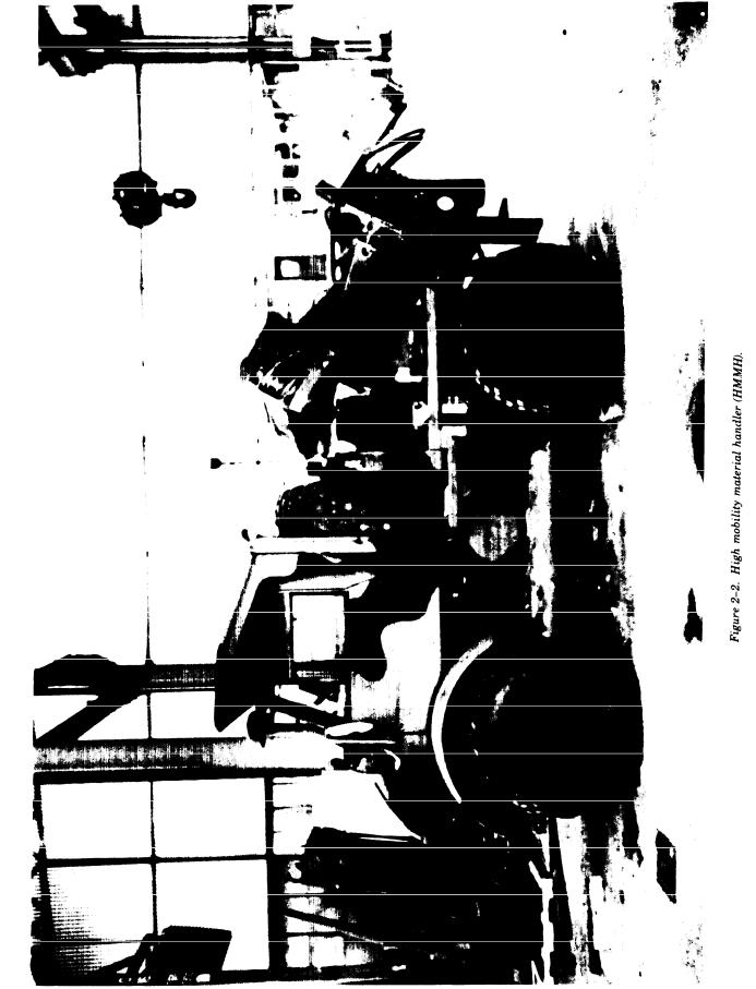
High mobility material handler (HMMH). . . . . . . . . . . . . . . . . . . . . . . . . . . . . . |
2-3 |
|
2-3 |
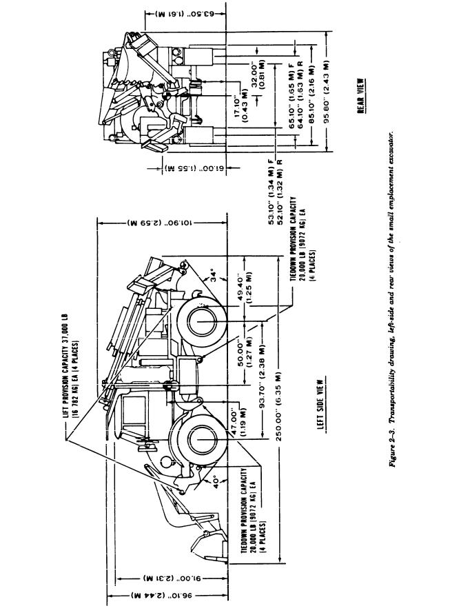
Transportability drawing, left-side and rear views of the small emplacement excavator . . . . . . . . . . . . . . . . . . |
2-4 |
|
2-4 |
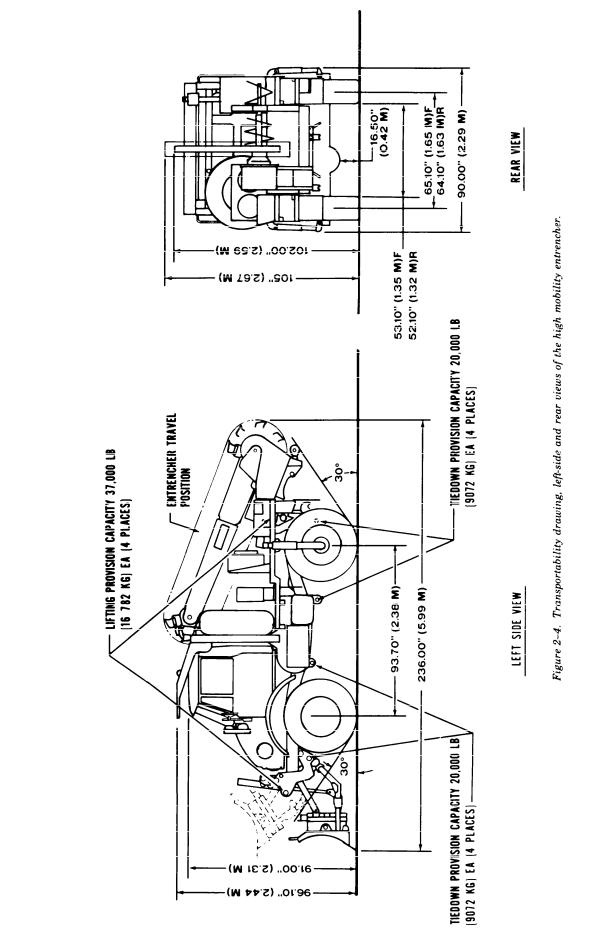
Transportability drawing, left-side and rear views of the high mobility entrenched . . . . . . . . . . . . . . . . . . . . . . |
2-5 |
|
2-5 |
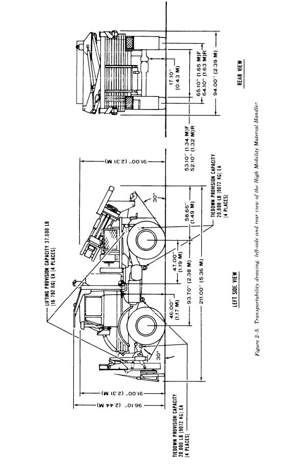
Transportability drawing, left-side and rear views of the high mobility material handler . . . . . . . . . . . . . . . . |
2-6 |
|
4-1 |
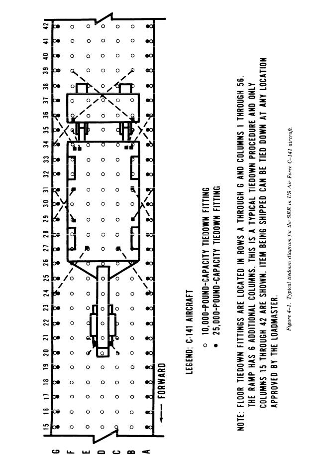
Typical tiedown diagram for the SEE in US Air Force C-141 aircraft . . . . . . . . . . . . . . . . . . . . . . . . . . . . . . . . . . |
4-3 |
|
4-2 |
Typical tiedown diagram for the HME in US Air Force C-130 aircraft . . . . . . . . . . . . . . . . . . . . . . . . . . . . . . . . . |
4-4 |
|
4-3 |
Typical tiedown diagram for the HMMH in US Air Force C-5 aircraft . . . . . . . . . . . . . . . . . . . . . . . . . . . . . . . . . |
4-5 |
|
4-4 |
SEE being lifted with single-hook method by CH-47 helicopter. . . . . . . . . . . . . . . . . . . . . . . . . . . . . . . . . . . . . . . . |
4-6 |
|
4-5 |
SEE being lifted with dual-hook method by CH-47 helicopter. . |
. . . . . . . . . . . . . . . . . . . . . . . . . . . . . . . . . . . . . . . |
4-7 |
4-6 |
SEE being lifted by CH-54 helicopter . . . . . . . . . . . . . . . . . . . . |
. . . . . . . . . . . . . . . . . . . . . . . . . . . . . . . . . . . . . . . . . . . . |
4-8 |
4-7 |
Front sling legs preparation on SEE (front view) . . . . . . . . . . . . |
. . . . . . . . . . . . . . . . . . . . . . . . . . . . . . . . . . . . . . . . . . |
4-9 |
4-8 |
Right rear sling leg preparation on SEE (rear view) . . . . . . . . . . |
. . . . . . . . . . . . . . . . . . . . . . . . . . . . . . . . . . . . . . . . . |
4-10 |
4-9 |
Left rear sling leg preparation on SEE (rear view) . . . . . . . . . . . |
. . . . . . . . . . . . . . . . . . . . . . . . . . . . . . . . . . . . . . . . . |
4-12 |
5-1 |
Typical tiedown diagram for the SEE, HME, and HMMH on an M345 trailer (side view) . . . . . . . . . . . . . . . . |
5-2 |
|
6-1 |
Typical four-leg sling-lifting diagram for the SEE, HME, and HMMH with wire rope . . . . . . . . . . . . . . . . . . . |
6-2 |
|
6-2 |
Typical blocking and tiedown of the SEE, HME, and HMMH in general-cargo and barge-type vessels . . . . |
6-3 |
|
6-3 |
Typical loading of the SEE, HME, and HMMH on a LASH lighter with wire rope, cable clamps, |
6-6 |
|
|
turnbuckles, and blocking . . . . . . . . . . . . . . . . . . . . . |
. . . . . . . . . . . . . . . . . . . . . . . . . . . . . . . . . . |
|
6-4 |
Typical tiedown of the SEE, HME, and HMMH on a RORO vessel . . . . . . . . . . . . . . . . . . . . . . . . . . . . . . . . . . . . . |
6-7 |
|
7-1 |
Typical blocking and tiedown for the SEE and HME on a CONUS general-purpose flatcar (side view) . . . . |
7-2 |
|
7-2 |
Typical blocking and tiedown for the SEE and HME on a CONUS general-purpose flatcar (rear view) . . . . |
7-3 |
|
7-3 |
Typical blocking and tiedown detail diagram . . . . . . . . . . . . . . . |
. . . . . . . . . . . . . . . . . . . . . . . . . . . . . . . . . . . . . . . . . . |
7-4 |
7-4 |
Typical tiedown for the SEE and variants on a CONUS conventional wood-deck, chain-tiedown flatcar |
7-8 |
|
|
(side view) . . . . . . . . . . . . . . . . . . . . . . . . . . . . . . . . . . . . . . . . . . . |
||
7-5 |
Typical tiedown for the SEE and variants on a CONUS conventional wood-deck, chain-tiedown flatcar |
7-9 |
|
|
(rear view) . . . . . . . . . . . . . . . . . . . . . . . . . . |
. . . . . . . . . . . . . . . . . . . . . . . . . . |
|
|
LIST OF TABLES |
|
|
Table |
|
|
Page |
5-1 |
Bill of Materials for Blocking and Tiedown of the SEE, HME, and HMMH on the M345 Trailer (Fig 5-1) |
5-3 |
|
5-2 |
Application of Materials for Blocking and Tiedown of the SEE, HME, and HMMH on the M345 Trailer |
5-3 |
|
|
(Fig 5-1) . . . . . . . . . . . . . . . . . . . . . . . . |
. . . . . . . . . . . . . . . . . . . . . . . . |
|
6-1 |
Bill of Materials for Blocking and Tiedown of a Typical SEE, HME, and HMMH in a General-Cargo |
6-4 |
|
|
Vessel (Fig 6-2) . . . . . . . . . . . . . . . . . . . . . . . . . . |
of. . .a. Typical. . . . . . .SEE,. . . . HME,. . . . . .and. . .HMMH. . . . . . .in. .a |
|
6-2 |
Application of Materials for Blocking and Tiedown |
6-4 |
|
|
General-Cargo Vessel (Fig 6-2) . . . . . . . . . . . . . . . . . . . . |
. . . . . . . . . . . . . . . . . . . . . . . . . . . . . . . . . . . . . . |
|
7-1 |
Bill of Materials for Blocking and Tiedown of the SEE and HME on a CONUS General-Purpose Flatcar |
7-5 |
|
|
(Figs 7-1 and 7-2) . . . . . . . . . . . . . . . . . . . . . . |
. . . . . . . . . . . . . . . . . . . . . . . . . . . . |
|
7-2 |
Application of Materials for Blocking and Tiedown of the SEE and HME on a CONUS General-Purpose |
7-5 |
|
|
Flatcar (Figs 7-1 and 7-2) . . . . . . . . . . . . . . |
. . . . . . . . . . . . . . . . . . . . . . . . . . |
|
7-3 |
Application of Chain Tiedowns for Securing the HMMH on HTTX or Similar Type of Flatcars (Figs 7-4 |
7-6 |
|
|
and 7-5) . . . . . . . . . . . . . . . . . . . . . . . . . . . . . . . |
. . . . . . . . . . . . . . . . . . . . . . . . . . . . . . . |
|
i i

T M 5 5 - 2 4 2 0 - 2 2 4 - 1 4
CHAPTER 1
INTRODUCTION
1-1. Purpose and Scope
This manual provides transportability guidance for logistical handling and movement of the small emplacement excavator (SEE), high mobility entrencher (HME), and high mobility material handler (HMMH). It contains information considered appropriate for safe transport of the SEE and its variants. The information includes significant technical and physical characteristics, as well as safety considerations, required for worldwide movement by the various transport modes. Where considered necessary, metric equivalents appear in parentheses following the dimensions or other measurements. This manual is for transportation officers and other personnel responsible for moving the SEE, HME, and HMMH, or for providing transport services.
1 - 2 . R e p o r t i n g o f R e c o m m e n d a t i o n s and Comments
Users of this manual are encouraged to submit
comments and to recommend changes for its im-
provement. Comments and recommendations should be prepared on DA Form 2028 (Recommended Changes to DA Publications and Blank Forms) and forwarded to Commander, Military Traffic Management Command Transportation Engineering Agency, ATTN: MTTE-TRS, PO Box 6276, Newport News, VA 23606–0276. Electrically transmitted messages should be addressed to CDR MTMCTEA FT EUSTIS VA//MTTE-TRS//.
1 - 3 . D e f i n i t i o n s o f W a r n i n g s , C a u - tions, and Notes
Throughout this manual, warnings, cautions, and notes emphasize important or critical guidance. They are used for the following conditions:
a.Warning. Instructions that, if not followed, could result in injury to or death of personnel.
b.Caution. Instructions that, if not strictly observed, could result in damage to or destruction of equipment.
c.Note. An operating procedure or condition that must be emphasized.
1-1

T M 5 5 - 2 4 2 0 - 2 2 4 - 1 4
CHAPTER 2
TRANSPORTABILITY DATA
Section I. GENERAL
2 - 1 . S c o p e
This chapter provides transportability characteristics of the SEE, HME, and HMMH.
2-2. Description
The SEE, HME, and HMMH are commercial items of construction equipment. The tractor portion of the equipment is a light truck chassis equipped with a diesel engine, multispeed range transmission, and offroad flotation tires. The tractor has a 45-mile-per-hour (72-km/h) highway convoy speed as well as a full drive rough-terrain capability.
a. The SEE tractor configuration consists of the basic tractor with a 3/4-cubic-yard-capacity front end loader and rear-mounted backhoe. The backhoe has a 7-cubic-foot-capacity bucket, as shown in figure 2-1.
b.The HME variant consists of the same basic tractor as the SEE, but with a dozer blade (85 inches wide and 32 inches high) on the front end and an entrencher on the rear. No photograph is available at this time.
c.The HMMH variant consists of the same basic tractor as the SEE, but with a 4,000-pound (1814-kg)-capacity forklift mounted to the front and a 6,000 pound (2722-kg)-capacity crane attached to the rear of the vehicle, as shown in figure 2-2.
2-3. Transportability Drawings
Figures 2-3 through 2-5 are detailed sideand rear-view transportability drawings of the SEE, HME, and HMMH with dimensions, tiedown and lifting provisions, and load-rating capacities.
2-1

T M 5 5 - 2 4 2 0 - 2 2 4 - 1 4
Figure 2-1.
2-2
T M 5 5 - 2 4 2 0 - 2 2 4 - 1 4
Figure 2-2.
2-3
T M 5 5 - 2 4 2 0 - 2 2 4 - 1 4
Figure 2-3.
2 - 4
T M 5 5 - 2 4 2 0 - 2 2 4 - 1 4
Figure 2-4.
2-5
T M 5 5 - 2 4 2 0 - 2 2 4 - 1 4
Figure 2-5.
2-6
T M 5 5 - 2 4 2 0 - 2 2 4 - 1 4
Section II. CHARACTERISTICS AND RELATED DATA
2-4. General Transportability Characteristics
Data contained here apply to the model numbers or national stock numbers (NSN) shown. Changes in model numbers or NSN may affect the loadability of the item as related to the guidance in this manual.
a. Small Emplacement Excavator.
National stock number . . . . . . . . . . . . . . . . . . . . . . . . . . . . . . . . . . . . . . . . . . . . . . . . . . . . . . . . . . . . . . . . . . . . . .
Line item number . . . . . . . . . . . . . . . . . . . . . . . . . . . . . . . . . . . . . . . . . . . . . . . . . . . . . . . . . . . . . . . . . . . . . . . . . . . . . .
Length:
Operational configuration (maximum) . . . . . . . . . . . . . . . . . . . . . . . . . . . . . . . . . . . . . . . . . . . . . . . . . . . . . . . .
Travel configuration . . . . . . . . . . . . . . . . . . . . . . . . . . . . . . . . . . . . . . . . . . . . . . . . . . . . . . . . . . . . . . . . . . . . . . . .
Width:
Operational configuration (maximum) . . . . . . . . . . . . . . . . . . . . . . . . . . . . . . . . . . . . . . . . . . . . . . . . . . . . . . . .
Travel configuration . . . . . . . . . . . . . . . . . . . . . . . . . . . . . . . . . . . . . . . . . . . . . . . . . . . . . . . . . . . . . . . . . . . . . . .
Height:
Operational configuration (maximum) . . . . . . . . . . . . . . . . . . . . . . . . . . . . . . . . . . . . . . . . . . . . . . . . . . . . . . . .
Travel configuration . . . . . . . . . . . . . . . . . . . . . . . . . . . . . . . . . . . . . . . . . . . . . . . . . . . . . . . . . . . . . . . . . . . . . . .
Area:
Operational configuration (maximum) . . . . . . . . . . . . . . . . . . . . . . . . . . . . . . . . . . . . . . . . . . . . . . . . . . . . . . . .
Travel configuration . . . . . . . . . . . . . . . . . . . . . . . . . . . . . . . . . . . . . . . . . . . . . . . . . . . . . . . . . . . . . . . . . . . . . . .
Volume:
Operational configuration (maximum). . . . . . . . . . . . . . . . . . . . . . . . . . . . . . . . . . . . . . . . . . . . . . . . . . . . . . . .
Travel configuration . . . . . . . . . . . . . . . . . . . . . . . . . . . . . . . . . . . . . . . . . . . . . . . . . . . . . . . . . . . . . . . . . . . . . . .
Weight:
Front axle . . . . . . . . . . . . . . . . . . . . . . . . . . . . . . . . . . . . . . . . . . . . . . . . . . . . . . . . . . . . . . . .
Rear axle . . . . . . . . . . . . . . . . . . . . . . . . . . . . . . . . . . . . . . . . . . . . . . . . . . . . . . . . . . . . . . . . . . . . . . . . . . . . . . . . . .
Total weight . . . . . . . . . . . . . . . . . . . . . . . . . . . . . . . . . . . . . . . . . . . . . . . . . . . . . . . . . . . . . . . . . . . . . . . . . . . . . . . .
Tires:
Number/size . . . . . . . . . . . . . . . . . . . . . . . . . . . . . . . . . . . . . . . . . . . . . . . . . . . . . . . . . . . . . . . . . . . . . . . . . . . . . . . .
Pressure:
Front . . . . . . . . . . . . . . . . . . . . . . . . . . . . . . . . . . . . . . . . . . . . . . . . . . . . . . . . . . . . . . . . . . . . . . . . . . . . . . . . . . . . . .
Rear . . . . . . . . . . . . . . . . . . . . . . . . . . . . . . . . . . . . . . . . . . . . . . . . . . . . . . . . . . . . . . . . . . . . . . . . . . . . . . . . . . . . . . .
Contact area:
Front . . . . . . . . . . . . . . . . . . . . . . . . . . . . . . . . . . . . . . . . . . . . . . . . . . . . . . . . . . . . . . . . . . . . . . . . . . . . . . . . . . . . . .
Rear . . . . . . . . . . . . . . . . . . . . . . . . . . . . . . . . . . . . . . . . . . . . . . . . . . . . . . . . . . . . . . . . . . . . . . . . . . . . . . . . . . . . . . .
Speed/range:
Maximum speed . . . . . . . . . . . . . . . . . . . . . . . . . . . . . . . . . . . . . . . . . . . . . . . . . . . . . . . . . . . . . . . . . . . . . . . . . . . .
Operational range . . . . . . . . . . . . . . . . . . . . . . . . . . . . . . . . . . . . . . . . . . . . . . . . . . . . . . . . . . . . . . . . . . . . . . . . . .
Ground clearances–differential . . . . . . . . . . . . . . . . . . . . . . . . . . . . . . . . . . . . . . . . . . . . . . . . . . . . . . . . . . . . . .
2420-01-160-2754
T34437
340.2in. (8.64 m)
250.0in. (6.35 m)
95.8in. (2.43 m)
95.8in. (2.43 m)
96.1in. (2.44m)
101.9in. (2.59 m)
226.3ft2 (21.05 m2)
166.3ft2 (15.47 m2)
1,720.7 ft3 (48.73 m3)
1,412.3 ft3 (39.99 m3)
8,760 lb (3973 kg)
7,160 lb (3248 kg)
15,920 lb (7221 kg)
4 ea 12.5 x 20
50 psi (344.40 kpa)
45 psi (310.30 kpa)
89.9 in.2 (0.06 m2)
95.5 in.2 (0.06 m2)
45 mph (72.41 km/h)
10 hours
17.1 in. (0.43 m)
b. High Mobility Entrenched.
National stock number. . . . . . . . . . . . . . . . . . . . . . . . . . . . . . . . . . . . . . . . . . . . . . . . . . . . . . . . . . . . . . . . . . . . .
Line item number . . . . . . . . . . . . . . . . . . . . . . . . . . . . . . . . . . . . . . . . . . . . . . . . . . . . . . . . . . . . . . . . . . . . . . . . . .
Length, travel configuration . . . . . . . . . . . . . . . . . . . . . . . . . . . . . . . . . . . . . . . . . . . . . . . . . . . . . . . . . . . . . . . . .
Width, travel configuration . . . . . . . . . . . . . . . . . . . . . . . . . . . . . . . . . . . . . . . . . . . . . . . . . . . . . . . . . . . . . . . . . .
Height, travel configuration . . . . . . . . . . . . . . . . . . . . . . . . . . . . . . . . . . . . . . . . . . . . . . . . . . . . . . . . . . . . . . . . .
Area, travel configuration.. . . . . . . . . . . . . . . . . . . . . . . . . . . . . . . . . . . . . . . . . . . . . . . . . . . . . . . . . . . . . . . . . .
Volume, travel configuration . . . . . . . . . . . . . . . . . . . . . . . . . . . . . . . . . . . . . . . . . . . . . . . . . . . . . . . . . . . . . . . .
Weight:
Front axle . . . . . . . . . . . . . . . . . . . . . . . . . . . . . . . . . . . . . . . . . . . . . . . . . . . . . . . . . . . . . . . . . . . . . . . . . . . . . . . . . . .
Rear axle . . . . . . . . . . . . . . . . . . . . . . . . . . . . . . . . . . . . . . . . . . . . . . . . . . . . . . . . . . . . . . . . . . . . . . . . . . . . . . . . . .
Total weight. . . . . . . . . . . . . . . . . . . . . . . . . . . . . . . . . . . . . . . . . . . . . . . . . . . . . . . . . . . . . . . . . . . . . . . . . . . . . . . .
Tires:
Number/size . . . . . . . . . . . . . . . . . . . . . . . . . . . . . . . . . . . . . . . . . . . . . . . . . . . . . . . . . . . . . . . . . . . . . . . . . . . . . . . .
Pressure:
Front . . . . . . . . . . . . . . . . . . . . . . . . . . . . . . . . . . . . . . . . . . . . . . . . . . . . . . . . . . . . . . . . . . . . . . . . . . . . . . . . . . . . . .
Rear . . . . . . . . . . . . . . . . . . . . . . . . . . . . . . . . . . . . . . . . . . . . . . . . . . . . . . . . . . . . . . . . . . . . . . . . . . . . . . . . . . . . . . .
2420-01-228-8610
T34437
236.0 in. (5.99 m)
90.0 in. (2.29 m)
105.0in. (2.67 m)
147.5ft2 (13.71 m2) 1,290.6 ft3 (36.55 m3)
7,830 lb (3551 kg)
7,670 lb (3479 kg)
15,500 lb (7030 kg)
4 ea 12.5 x 20
55 psi (379.72 kpa)
55 psi (379.72 kpa)
2-7
T M 5 5 - 2 4 2 0 - 2 2 4 - 1 4
Contact area:
Front . . . . . . . . . . . . . . . . . . . . . . . . . . . . . . . . . . . . . . . . . . . . . . . . . . . . . . . . . . . . . . . . . . . . . . . .
Rear . . . . . . . . . . . . . . . . . . . . . . . . . . . . . . . . . . . . . . . . . . . . . . . . . . . . . . . . . . . . . . . . . . . . . . .
Speed/range:
Maximum speed . . . . . . . . . . . . . . . . . . . . . . . . . . . . . . . . . . . . . . . . . . . . . . . . . . . . . . . . .
Operational range . . . . . . . . . . . . . . . . . . . . . . . . . . . . . . . . . . . . . . . . . . . . . . . . . . . . . . . . . . . . .
Ground clearances–differential. . . . . . . . . . . . . . . . . . . . . . . . . . . . . . . . . . . . . . . . . . . . . . . . . . . . . . . . . . . . . .
c. High Mobility Material Handler.
National stock number . . . . . . . . . . . . . . . . . . . . . . . . . . . . . . . . . . . . . . . . . . . . . . . . . . . . . . . . .
Line item number . . . . . . . . . . . . . . . . . . . . . . . . . . . . . . . . . . . . . . . . . . . . . . . . . . . . . . . . . . . . . . .
Length, travel configuration . . . . . . . . . . . . . . . . . . . . . . . . . . . . . . . . . . . . . . . . . . . . . . . . . . . . . . . . . . . . . . . . .
Width, travel configuration . . . . . . . . . . . . . . . . . . . . . . . . . . . . . . . . . . . . . . . . . . . . . . . . . . . . . . . . .
Height, travel configuration . . . . . . . . . . . . . . . . . . . . . . . . . . . . . . . . . . . . . . . . . . . . . . . . . . . . . . . .
Area, travel configuration . . . . . . . . . . . . . . . . . . . . . . . . . . . . . . . . . . . . . . . . . . . . . . . . . . . . . . . . . . . . .
Volume, travel configuration . . . . . . . . . . . . . . . . . . . . . . . . . . . . . . . . . . . . . . . . . . . . . . . . . . . . . . . . . . . . . . . .
Weight:
Front axle . . . . . . . . . . . . . . . . . . . . . . . . . . . . . . . . . . . . . . . . . . . . . . . . . . . . . . . . . . . . . . . . . . . . . . . . . . . . . . . . . . . . . . . . . . . . . . . . .
Rear axle . . . . . . . . . . . . . . . . . . . . . . . . . . . . . . . . . . . . . . . . . . . . . . . . . . . . . . . . . . . . . . . . . . . . . . . . . . . . . . . . . . . . . . . . .
Total weight . . . . . . . . . . . . . . . . . . . . . . . . . . . . . . . . . . . . . . . . . . . . . . . . . . . . . . . . . . . . . . . . . . . . .
Tires:
Number/size . . . . . . . . . . . . . . . . . . . . . . . . . . . . . . . . . . . . . . . . . . . . . . . . . . . . . . . . . . . . . . . . . . . . . . . . . . . . . . .
Pressure:
Front . . . . . . . . . . . . . . . . . . . . . . . . . . . . . . . . . . . . . . . . . . . . . . . . . . . . . . . . . . . . . . . . . . . . . . . . . . . . . . . . . . .
Rear . . . . . . . . . . . . . . . . . . . . . . . . . . . . . . . . . . . . . . . . . . . . . . . . . . . . . . . . . . . . . . . . . . . . . . . . . . . . . . . . . .
Contact area:
Front . . . . . . . . . . . . . . . . . . . . . . . . . . . . . . . . . . . . . . . . . . . . . . . . . . . . . . . . . . . . . . . . . . . . . . . . . . . . . . . . . . . . . . . . . . . . . .
Rear . . . . . . . . . . . . . . . . . . . . . . . . . . . . . . . . . . . . . . . . . . . . . . . . . . . . . . . . . . . . . . . . . . . . . . .
Speed/range:
Maximum speed . . . . . . . . . . . . . . . . . . . . . . . . . . . . . . . . . . . . . . . . . . . . . . . . . . . . . . . . . . . . . .
Operational range . . . . . . . . . . . . . . . . . . . . . . . . . . . . . . . . . . . . . . . . . . . .
Ground clearances–differential . . . . . . . . . . . . . . . . . . . . . . . . . . . . . . . . . . . . . . . . . . . . . . . . . . . . . . . . . . . . . .
77.9 in.2 (0.05 m2)
76.0 in.2 (0.04 m2)
45 mph (72.41 km/h)
10 hours
16.5 in. (0.42 m)
2420-01-205-3636
Z90450
211.0 in. (5.36 m)
94.0in. (2.39 m)
96.1in. (2.44 m)
137.7ft2 (12.80 m2) 1,130.0 ft3 (30.89 m3)
8,018 lb (3637 kg)
7,632 lb (3462 kg)
15,650 lb (7099 kg)
4 ea 12.5 x 20
55 psi (379.72 kpa)
55 psi (379.72 kpa)
79.5 in.2 (0.05 m2)
76.1 in.2 (0.04 m2)
45 mph (72.41 km/h)
10 hours
17.1 in. (0.43m)
2-5. Reduced Configuration
Lower cost shipping can be obtained by reducing each SEE, HME, and HMMH to its minimum dimensions for terminal handling and ocean transport. Both side mirrors are to be folded in, and the rear-mounted attachment is placed in the travel position.
2-6. Unusual Characteristics
These vehicles have no unusual characteristics
that would require special attention be given to
temperature, atmospheric pressure, or humidity
variations during their exposure to normal trans-
portation environments.
2-7. Hazardous and Dangerous Characteristics
Under usual circumstances, the SEE, HME, and HMMH will not present any hazardous or dangerous characteristics during exposure to normal transportation environments.
NOTE
Those regulations and/or transportation procedures normally associated with vehicles containing diesel fuel apply.
2-8

T M 5 5 - 2 4 2 0 - 2 2 4 - 1 4
CHAPTER 3
SAFETY
3 - 1 . G e n e r a l
General safety considerations and precautions for movement are as follows:
a.Check each vehicle to ensure that all loose items are properly secured.
b.When backing a vehicle, ensure that no personnel or obstacles are in danger of being hurt or damaged by the vehicle.
WARNING
WARNING
When vehicle engine is operating, provide
proper ventilation during loading and un-
loading operations. Prolonged inhalation
of carbon monoxide fumes could be fatal.
3-2. Specific Safety Requirements
Appropriate chapters of this manual contain per-
tinent safety requirements by individual mode.
Fire extinguishers must be readily available during all loading and unloading operations.
3-1

T M 5 5 - 2 4 2 0 - 2 2 4 - 1 4
CHAPTER 4
AIR TRANSPORTABILITY GUIDANCE
4 - 1 . S c o p e
This chapter provides air transportability guidance for movement of the SEE, HME, and HMMH. It covers significant technical and physical characteristics and safety considerations. Also, it prescribes the materials required to prepare, load, and unload the SEE, HME, and HMMH when transported in the C–130, C–141, and C–5 US Air Force aircraft and the Boeing 747 Civil Reserve Air Fleet (CRAF) aircraft.
4-2. Maximum Use of Aircraft Capac-
ity
Additional cargo, including personnel within allowable load limits and restrictions prescribed by pertinent safety regulations, may be transported with these vehicles on US Air Force aircraft.
4 - 3 . A p p l i c a b i l i t y
a. US Air Force Aircraft. When prepared for loading as described in paragraph 4-5, the SEE, HME, and HMMH are transportable in C-130, C-141, and C-5 aircraft.
b.Tiedown Devices. The SEE, HME, and HMMH will be tied down according to section IV of applicable procedures in TO 1C-XXX–9.
c.Loadmaster. The loadmaster will ensure that
the loaded equipment is secured according to restraint criteria outlined in TO 1C–XXX–9.
NOTE
Air Force aircraft loads in this manual are illustrated to a minimum restraint of 3 g forward, 1.5 g aft, 1.5 g lateral and 2 g vertical. (Reference 1C-XXX-9 and MIL-STD-1791.)
4 - 4 . S a f e t y
In addition to safety precautions contained in chapter 3, the following precautions apply for the SEE, HME, and HMMH:
a.Ensure that the fuel tanks are not less than one-fourth or more than three-fourths full.
b.Check each vehicle carefully to ensure that
all loose items are properly secured.
c.Check each vehicle to ensure there are no fluid leaks.
d.Check all tiedown provisions and attached structural members for any damage.
e.Check tire pressure to ensure tires are at recommended highway pressure.
f. Check batteries to ensure they are protected against short circuits and secured so that leakage of acid cannot occur (reference TM 38–250, para 8-47a). Also, check the fuel tanks and hydraulic systems to ensure they comply with TM 38–250.
WARNING
Fire extinguishers must be readily available during all loading and unloading.
WARNING
Provide proper ventilation during loading. Prolonged inhalation of exhaust fumes could be fatal.
WARNING
Do not allow the vehicle to exceed 3 miles per hour (walking speed) inside the aircraft or on the loading ramps.
4-5. Preparation of Equipment
a.Fold both mirrors and secure them with rope to the roll over protection structure (ROPS).
b.Secure rear attachments with 1/2-inch wire rope (safety cable) and two clips, when shipped in the travel position. Install wire rope taut (not tight) around the ROPS (or tiedown provision as directed) and rear attachment to restrain the attachment in case the mechanical lock is not engaged or fails.
4-6. Transport by US Aircraft
a. The SEE, when shipped in C–130 and C–141 aircraft, will have the backhoe attachment in the operational configuration. The SEE should be backed into the C-130 and C-141 aircraft using two qualified operators. One driver operates the tractor and the other operates the backhoe, adjusting height during loading and unloading operations. Each SEE requires two stacks of parking shoring (2 x 6 inches x 4 feet, two per stack) between the front end loader and the aircraft floor. Also, place two stacks of shoring (2 x 6 inches x 4 feet, two per stack) under lowered bucket and aircraft floor.
b. The HME and HMMH, when shipped in C–130 and C–141 aircraft, must be in the travel configuration.
(1) HME. Install 1/2-inch wire rope (safety cable) through ROPS and over entrenched attachment, forming a loop. Secure the loop by pulling and installing the wire rope taut (not tight) with two 1/2-inch clips. Each HME requires two stacks
4-1
T M 5 5 - 2 4 2 0 - 2 2 4 - 1 4
of parking shoring (2 x 6 inches x 4 feet, two per stack) between the front dozer blade and the aircraft floor.
(2) HMMH. Install 1/2-inch wire rope (safety cable) around top crane arm and through left center tiedown provision on chassis, forming a loop. Secure the loop by pulling the wire rope taut (not tight) and installing two 1/2-inch clips. Repeat same procedure for right side, except loop wire rope through right provision on chassis. Each HMMH requires two stacks of parking shoring (2 x 6 inches x 5 feet, two per stack) between the front forklift tines and the aircraft floor. Also the rear outriggers are to be secured with 1/2-inch wire rope (safety cable) looped around each outrigger and secured with two 1/2-inch clips.
c. The C–5 aircraft can transport the SEE, HME, and HMMH in the travel configurations.
(1)SEE. Install 1/2-inch wire rope (safety cable) taut (not tight) around the ROPS and the backhoe attachment and secure with two 1/2-inch clips. Also, install on right outrigger a 1/2-inch wire rope (safety cable) taut (not tight) through the bucket tiedown provisional and around outriggers. Repeat procedures for left outrigger. Each SEE requires two stacks of parking shoring (2 x 6 inches x 4 feet, two per stack) between the front end loader and the aircraft floor.
(2)HME and HMMH. To transport the HME and HMMH in the C–5 aircraft, follow the same
procedures in paragraph 4-6b.
d.The shoring is required to protect the aircraft floor and any downward motion of the front or rear implements on the aircraft floor.
e.All shoring material will be furnished by the shipper and installed as directed by the aircraft loadmaster.
f.The aircraft commander or his/her representative ensures that the vehicles are loaded/unloaded and properly secured in the aircraft according to the criteria in section IV of the appropriate technical order.
g.Typical tiedown diagrams (figs 4-1 through 4–3) are based on acceptable methods. They can be
used as a guide for loading and securing the SEE, HME, and HMMH aboard aircraft and also for preparing a vehicle for air transport. The tiedowns are part of the aircraft equipment.
4-7. Transport by LVAD and LAPE
The SEE is certified for low altitude parachute extraction (LAPE) from US Air Force C–130 aircraft and certified for low velocity airdrop (LVAD) from US Air Force C-130 and C-141 aircraft. Preparation and procedures for LAPE and LVAD
airdrops are described in FM 10–539 and TO 13C7-1-17.
4-8. Helicopter Transport
The SEE is within the external lift capability of the CH–47D helicopter in either single-hook (fig 4–3) or dual-hook (fig 4–4) configuration at airspeeds of 100 knots. The load is also suitable for external transport by the CH–54 helicopter (fig 4-5) at airspeeds of 95 knots.
a.Materials.
(1)Sling set (25,000-pound capacity) – one
each.
(2)Nylon cord, Type III-as required.
(3)Cotton webbing–as required.
(4)Tape, adhesive, pressure-sensitive, 2-inch roll—as required.
(5)Felt, padding, sheet–four each (for cushioning material).
b.Preparation.
(1)Ensure that the front end loader assembly travel locks at the ends of both front end loader boom cylinders are properly pinned in place.
(2)Secure steering wheel, doors, and all loose equipment with cord and tape as necessary.
(3)Fold side mirrors inboard and tie or tape as required.
(4)Tape windshield wipers to windshield.
(5)Securely tie and tape engine compartment
hood.
(6)Tie or tape the hydraulic lines and hoses close to the forward lifting provisions to prevent possible entanglement during hookup.
c.Rigging Procedures.
(1)Place apex fitting on top of the falling object protection system (FOPS). Route the outer sling legs (1 and 2) to the front of the SEE and the inner sling legs (3 and 4) to the rear of the SEE.
NOTE
Sling legs 1 and 3 should be the same side of the load.
(2) Loop the chain ends of sling legs 1 and 2 through the respective front lifting provisions, and insert link 3 into the grabhook. Wrap a felt sheet around the chain ends of the sling legs and secure with tape or nylon cord (fig 4–7).
(3) Loop the chain end of sling leg 3 through the right rear lifting provision (closest to the backhoe bucket) and insert link 10 into the grabhook. Wrap a felt sheet (cushioning material) around the chain end of the sling leg and secure with tape or nylon cord. Tape or tie excess chain links (fig 4-8).
4-2
T M 5 5 - 2 4 2 0 - 2 2 4 - 1 4
Figure 4-1.
4-3
Loading...