


MAKITA DRT50Z Manual
|
EN |
Cordless Trimmer |
INSTRUCTION MANUAL |
13 |
|
|
|
|
|
|
|
Batteridriven kantfräs |
BRUKSANVISNING |
22 |
|
SV |
|||
|
|
|
|
|
|
|
Batteridrevet |
BRUKSANVISNING |
31 |
|
NO |
|||
|
tilskjæringsmaskin |
|||
|
|
|
|
|
|
|
Akkukäyttöinen jyrsin |
KÄYTTÖOHJE |
40 |
|
FI |
|||
|
|
|
|
|
|
|
Bezvadu apgriezējmašīna |
LIETOŠANAS INSTRUKCIJA |
49 |
|
LV |
|||
|
|
|
|
|
|
|
Belaidė freza |
NAUDOJIMO INSTRUKCIJA |
58 |
|
LT |
|||
|
|
|
|
|
|
|
Akuga servamismasin |
KASUTUSJUHEND |
67 |
|
ET |
|||
|
|
|
|
|
|
|
Аккумуляторный Триммер |
РУКОВОДСТВО ПО |
76 |
|
RU |
|||
|
ЭКСПЛУАТАЦИИ |
|||
|
|
|
|
DRT50
1 |
2 |
3 |
Fig.1 |
|
1 |
|
2 |
Fig.2 |
|
1 |
2 |
Fig.3 |
1 |
Fig.4 |
2 |
1 |
Fig.5 |
1 |
Fig.6 |
1 |
2 |
Fig.7 |
1 |
2
3
Fig.8
2

2 |
1 |
Fig.9 |
1 |
2 |
|
Fig.10 |
3 |
|
|
|
1 |
Fig.11 |
|
1 |
|
2
Fig.12
1 |
Fig.13 |
1 |
Fig.14 |
1 |
Fig.15 |
1 |
Fig.16 |
3
1 |
2 |
|
|
|
|
3 |
|
|
|
4 |
|
|
|
5 |
|
Fig.17 |
|
|
|
|
|
|
1 |
1 |
2 |
Fig.21 |
|
|
|
|
|
|
|
3 |
|
|
|
1 |
|
|
|
4 |
|
Fig.18 |
|
|
|
1 |
|
|
|
|
|
1 |
2 |
|
|
Fig.22 |
|
Fig.19 |
|
|
|
|
|
Fig.23 |
|
|
|
1 |
|
Fig.20 |
|
|
|
|
|
4 |
|
1 |
Fig.24 |
1 |
2 |
3 |
Fig.25 |
1 |
2 |
Fig.26 |
5 |
1 |
2 |
3 |
Fig.27 |
1 |
Fig.28 |
1 |
Fig.29 |
1 |
2 |
Fig.30 |
1 |
Fig.31 |
1 |
Fig.32 |
1 |
2 |
3 |
Fig.33 |
1 |
2 |
3 |
Fig.34 |
6 |
1 |
2 |
Fig.35 |
1 |
Fig.36 |
1 |
2 |
Fig.37 |
1 |
2 |
3 |
Fig.38 |
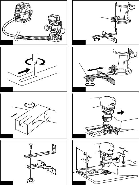
Fig.39 |
Fig.40 |
1 |
2 |
3 |
Fig.41 |
1 |
2 
Fig.42
1 |
Fig.43 |
1 |
Fig.44 |
Fig.45 |
A |
Fig.46
7
1 |
Fig.47 |
1 |
Fig.48 |
1 |
2 |
Fig.49 |
1 |
2 |
Fig.50 |
8 |
Fig.51 |
|
1 |
2 |
|
|
|
3 |
Fig.52 |
4 |
|
Fig.53 |
1 |
Fig.54
1 |
|
|
|
2 |
|
Fig.55 |
Fig.59 |
|
1 |
1 |
2 |
|
2 |
|
Fig.56 |
3 |
|
|
|
Fig.60 |
Fig.57 |
1 |
|
1 |
1 |
2 |
|
2 |
|
Fig.61 |
Fig.58 |
|
|
9 |
1 |
|
|
1 |
|
2 |
2 |
|
|
Fig.66 |
Fig.62 |
|
1 |
|
2 |
3 |
|
|
|
4 |
|
Fig.67 |
Fig.63 |
|
|
1 |
|
Fig.68 |
Fig.64 |
|
|
A |
|
Fig.69 |
Fig.65 |
|
10
1 |
2 |
|
3 |
Fig.70 |
|
D |
|
L1 |
|
L2 |
|
A |
|
Fig.71 |
|
D |
|
L1 |
|
L2 |
|
A |
|
R |
|
Fig.72 |
|
|
11 |
|
D |
|
|
L1 |
|
|
L2 |
|
|
θ |
|
|
A |
|
Fig.73 |
|
|
|
D |
|
|
|
L1 |
|
L2 |
|
|
L3 |
|
Fig.74 |
A |
|
|
D |
|
|
L3 |
L1 |
|
|
|
|
L2 |
|
|
L4 |
|
Fig.75 |
A |
|
|
D |
|
|
L3 |
L1 |
|
L2 |
|
|
R |
|
|
A2 |
|
|
A1 |
|
Fig.76 |
|
|
D |
|
|
|
L3 |
L1 |
|
θ |
L2 |
|
|
|
A |
|
|
Fig.77 |
|
|
D |
|
|
|
|
L1 |
|
L2 |
|
A |
R |
|
|
|
|
Fig.78 |
|
|
D |
|
|
|
|
L1 |
|
L2 |
|
A |
|
|
Fig.79 |
|
|
D |
|
|
|
L3 |
L1 |
|
L2 |
|
A2 |
R |
|
|
|
|
A1 |
|
|
Fig.80 |
|
|
|
|
12 |
|
D |
|
|
|
L1 |
|
|
L2 |
|
|
θ |
|
A2 |
|
Fig.81 |
A1 |
|
|
|
|
|
D |
|
|
L3 |
L1 |
|
R L2 |
|
|
A3 |
|
|
|
|
A2 |
|
|
|
Fig.82 |
A1 |
|
|
|
|
D |
|
|
|
|
|
L3 |
L1 |
|
|
|
|
L2 |
|
|
A4 |
R |
|
|
|
|
|
|
|
|
A3 |
|
|
|
|
A2 |
|
|
|
Fig.83 |
A1 |
|
|
|
|
D |
|
|
|
|
|
|
L3 |
L1 |
|
|
|
L2 |
|
|
|
|
R1 |
|
|
A2 |
R2 |
|
|
|
|
|
|
|
Fig.84 |
A1 |
|
|
|
|
|
|
|
|

ENGLISH (Original instructions)
SPECIFICATIONS
Model: |
DRT50 |
|
|
Collet chuck capacity |
6 mm, 8 mm, 1/4", or 3/8" |
No load speed |
10,000 - 30,000 min-1 |
Overall length |
226 mm |
Rated voltage |
D.C. 18 V |
Standard battery cartridge |
BL1815N / BL1820 / BL1820B / BL1830 / BL1830B / BL1840 / |
|
BL1840B / BL1850 / BL1850B / BL1860B |
Net weight |
1.8 - 2.1 kg |
|
|
•Due to our continuing program of research and development, the speciications herein are subject to change without notice.
•Speciications and battery cartridge may differ from country to country.
•The weight may differ depending on the attachment(s), including the battery cartridge. The lightest and heavi- est combination, according to EPTA-Procedure 01/2014, are shown in the table.
Intended use
The tool is intended for lush trimming and proiling of wood, plastic and similar materials.
Noise
The typical A-weighted noise level determined accord-
ing to EN60745:
Sound pressure level (LpA) : 78 dB(A) Uncertainty (K) : 3 dB(A)

 WARNING: Wear ear protection.
Vibration
The vibration total value (tri-axial vector sum) deter- mined according to EN60745:
Work mode: rotation without load
Vibration emission (ah) : 2.5 m/s2 or less Uncertainty (K) : 1.5 m/s2
Work mode: cutting grooves in MDF
Vibration emission (ah) : 4.5 m/s2 Uncertainty (K) : 1.5 m/s2
NOTE: The declared vibration emission value has been
measured in accordance with the standard test method and may be used for comparing one tool with another.
NOTE: The declared vibration emission value may also be used in a preliminary assessment of exposure.
 WARNING: The vibration emission during actual use of the power tool can differ from the declared
emission value depending on the ways in which the tool is used.
 WARNING: Be sure to identify safety measures
to protect the operator that are based on an estima- tion of exposure in the actual conditions of use (taking account of all parts of the operating cycle such as
the times when the tool is switched off and when it is running idle in addition to the trigger time).
EC Declaration of Conformity
For European countries only
The EC declaration of conformity is included as Annex A to this instruction manual.
SAFETY WARNINGS
General power tool safety warnings
 WARNING: Read all safety warnings, instructions, illustrations and speciications provided with this power tool. Failure to follow all instructions listed below may result in electric shock, ire and/or serious injury.
Save all warnings and instruc-
tions for future reference.
The term "power tool" in the warnings refers to your mains-operated (corded) power tool or battery-operated (cordless) power tool.
Cordless trimmer safety warnings
1.Hold power tool by insulated gripping surfaces,
because the cutter may contact hidden wiring.
Cutting a "live" wire may make exposed metal parts of the power tool "live" and shock the operator.
2.Use clamps or another practical way to secure and support the workpiece to a stable platform.
Holding the work by your hand or against the body leaves it unstable and may lead to loss of control.
3.Wear hearing protection during extended period of operation.
4.Handle the trimmer bits very carefully.
5.Check the trimmer bit carefully for cracks or damage before operation. Replace cracked or damaged bit immediately.
13 ENGLISH

6.Avoid cutting nails. Inspect for and remove all nails from the workpiece before operation.
7.Hold the tool irmly.
8.Keep hands away from rotating parts.
9.Make sure the trimmer bit is not contacting the workpiece before the switch is turned on.
10.Before using the tool on an actual workpiece, let it run for a while. Watch for vibration or wobbling that could indicate improperly installed bit.
11.Be careful of the trimmer bit rotating direction and the feed direction.
12.Do not leave the tool running. Operate the tool only when hand-held.
13.Always switch off and wait for the trimmer bit to come to a complete stop before removing the tool from workpiece.
14.Do not touch the trimmer bit immediately after operation; it may be extremely hot and could burn your skin.
15.Do not smear the tool base carelessly with thinner, gasoline, oil or the like. They may cause cracks in the tool base.
16.Use trimmer bits of the correct shank diameter suitable for the speed of the tool.
17.Some material contains chemicals which may be toxic. Take caution to prevent dust inhalation and skin contact. Follow material supplier safety data.
18.Always use the correct dust mask/respirator for the material and application you are working with.
SAVE THESE INSTRUCTIONS.
 WARNING: DO NOT let comfort or familiarity with product (gained from repeated use) replace strict adherence to safety rules for the subject product. MISUSE or failure to follow the safety rules stated in this instruction manual may cause serious personal injury.
Important safety instructions for battery cartridge
1.Before using battery cartridge, read all instructions and cautionary markings on (1) battery charger, (2) battery, and (3) product using battery.
2.Do not disassemble battery cartridge.
3.If operating time has become excessively shorter, stop operating immediately. It may result in a risk of overheating, possible burns and even an explosion.
4.If electrolyte gets into your eyes, rinse them out with clear water and seek medical attention right away. It may result in loss of your eyesight.
5.Do not short the battery cartridge:
(1)Do not touch the terminals with any conductive material.
(2)Avoid storing battery cartridge in a container with other metal objects such as nails, coins, etc.
(3)Do not expose battery cartridge to water
or rain.
A battery short can cause a large current low, overheating, possible burns and even a
breakdown.
6.Do not store the tool and battery cartridge in locations where the temperature may reach or exceed 50 °C (122 °F).
7.Do not incinerate the battery cartridge even if
it is severely damaged or is completely worn out. The battery cartridge can explode in a ire.
8.Be careful not to drop or strike battery.
9.Do not use a damaged battery.
10.The contained lithium-ion batteries are subject to the Dangerous Goods Legislation requirements.
For commercial transports e.g. by third parties, forwarding agents, special requirement on pack-
aging and labeling must be observed.
For preparation of the item being shipped, consult- ing an expert for hazardous material is required.
Please also observe possibly more detailed
national regulations.
Tape or mask off open contacts and pack up the battery in such a manner that it cannot move around in the packaging.
11.Follow your local regulations relating to disposal of battery.
12.Use the batteries only with the products speciied by Makita. Installing the batteries to non-compliant products may result in a ire, exces- sive heat, explosion, or leak of electrolyte.
SAVE THESE INSTRUCTIONS.
 CAUTION: Only use genuine Makita batteries.
Use of non-genuine Makita batteries, or batteries that
have been altered, may result in the battery bursting causing ires, personal injury and damage. It will also void the Makita warranty for the Makita tool and
charger.
Tips for maintaining maximum battery life
1.Charge the battery cartridge before completely discharged. Always stop tool operation and charge the battery cartridge when you notice less tool power.
2.Never recharge a fully charged battery cartridge. Overcharging shortens the battery service life.
3.Charge the battery cartridge with room temperature at 10 °C - 40 °C (50 °F - 104 °F). Let a hot battery cartridge cool down before charging it.
4.Charge the battery cartridge if you do not use it for a long period (more than six months).
14 ENGLISH

FUNCTIONAL DESCRIPTION
 CAUTION: Always be sure that the tool is switched off and the battery cartridge is removed before adjusting or checking function on the tool.
Installing or removing battery cartridge
 CAUTION: Always switch off the tool before installing or removing of the battery cartridge.
 CAUTION: Hold the tool and the battery cartridge irmly when installing or removing battery
cartridge. Failure to hold the tool and the battery cartridge irmly may cause them to slip off your hands
and result in damage to the tool and battery cartridge and a personal injury.
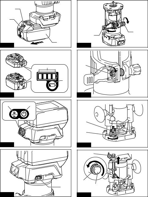
► Fig.1: 1. Red indicator 2. Button 3. Battery cartridge
To remove the battery cartridge, slide it from the tool while sliding the button on the front of the cartridge.
To install the battery cartridge, align the tongue on the battery cartridge with the groove in the housing and slip
it into place. Insert it all the way until it locks in place with a little click. If you can see the red indicator on the upper side of the button, it is not locked completely.
 CAUTION: Always install the battery cartridge
fully until the red indicator cannot be seen. If not, it may accidentally fall out of the tool, causing injury to
you or someone around you.
 CAUTION: Do not install the battery cartridge forcibly. If the cartridge does not slide in easily, it is
not being inserted correctly.
Indicating the remaining battery capacity
Only for battery cartridges with the indicator
► Fig.2: 1. Indicator lamps 2. Check button
Press the check button on the battery cartridge to indi- cate the remaining battery capacity. The indicator lamps light up for a few seconds.
|
Indicator lamps |
Remaining |
|
|
capacity |
Lighted |
Off |
Blinking |
|
|
75% to 100% |
|
|
50% to 75% |
|
|
25% to 50% |
|
|
0% to 25% |
|
|
Charge the |
|
|
battery. |
|
|
The battery |
|
|
may have |
|
|
malfunctioned. |
NOTE: Depending on the conditions of use and the ambient temperature, the indication may differ slightly from the actual capacity.
Tool / battery protection system
The tool is equipped with a tool/battery protection sys- tem. This system automatically cuts off power to the motor to extend tool and battery life. The tool will auto- matically stop during operation if the tool or battery is placed under one of the following conditions:
Overload protection
When the battery is operated in a manner that causes it to draw an abnormally high current, the tool automat-
ically stops without any indication. In this situation, turn the tool off and stop the application that caused the tool to become overloaded. Then turn the tool on to restart.
Overheat protection
When the tool or battery is overheated, the tool stops
automatically and the lamp blinks. In this case, let the tool and battery cool before turning the tool on again.
Overdischarge protection
When the battery capacity is not enough, the tool stops automatically. In this case, remove the battery from the
tool and charge the battery.
Switch action
To turn on the tool, press the lock/unlock button. The tool turns into the standby mode. To start the tool, press the start/stop button in the standby mode. To stop the tool, press the start/stop button again. The tool turns into the standby mode. To turn off the tool, press the
lock/unlock button in the standby mode.
► Fig.3: 1. Lock/unlock button 2. Start/stop button
NOTE: If the tool is left for 10 seconds without any
operation in the standby mode, the tool automatically turns off and the lamp goes off.
NOTE: You can also stop and turn off the tool by pressing the lock/unlock button while the tool is operating.
Lighting up the front lamp
 CAUTION: Do not look in the light or see the source of light directly.
To turn on the lamp, press the lock/unlock button. To turn off the lamp, press the lock/unlock button again.
NOTICE: When the tool is overheated, the lamp lickers. Cool down the tool fully before operating
the tool again.
NOTE: Use a dry cloth to wipe the dirt off the lens of the lamp. Be careful not to scratch the lens of lamp, or
it may lower the illumination.
15 ENGLISH

Speed adjusting dial
The rotation speed of the tool can be changed by turn- ing the speed adjusting dial. The table below shows
the number on the dial and the corresponding rotation
speed.
► Fig.4: 1. Speed adjusting dial
Number |
Speed |
|
|
1 |
10,000 min-1 |
2 |
15,000 min-1 |
3 |
20,000 min-1 |
4 |
25,000 min-1 |
5 |
30,000 min-1 |
NOTICE: If the tool is operated continuously at low speed for a long time, the motor will get overloaded, resulting in tool malfunction.
NOTICE: When changing the speed dial from "5" to "1", turn the dial counterclockwise. Do not turn the dial clockwise forcibly.
Electronic function
The tool is equipped with the electronic functions for easy operation.
•Constant speed control
The speed control function provides the constant rotation speed regardless of load conditions.
•Soft start
The soft-start function minimizes start-up shock, and makes the tool start smoothly.
Adjusting cutting depth
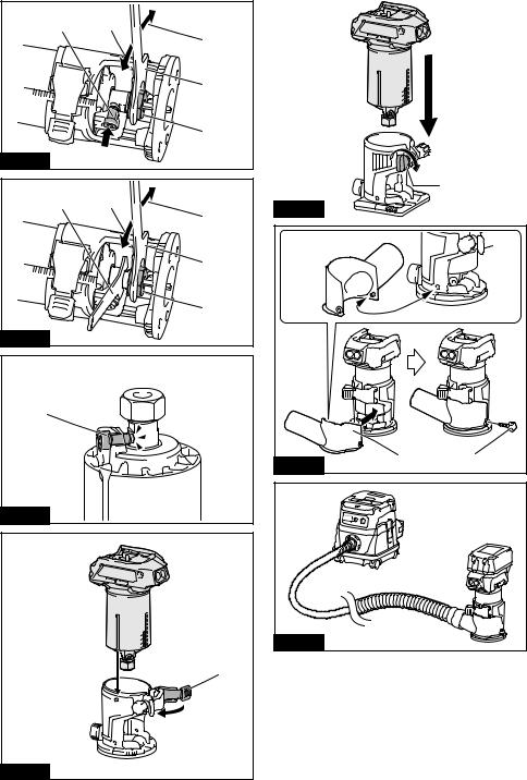
To adjust the cutting depth, open the lock lever, then move the tool base up or down by turning the adjusting screw. After the adjustment, close the lock lever irmly. ► Fig.5: 1. Lock lever 2. Adjusting screw
NOTICE: If the tool is not secured after closing the lock lever, tighten the hex nut, and then close the lock lever.
► Fig.6: 1. Hex nut
Adjusting cutting depth with the plunge base
Optional accessory
1.Place the tool on the lat surface.
2.Select the stopper screw by rotating the stopper
base.
► Fig.7: 1. Stopper screw 2. Stopper base
3.Loosen the stopper pole ixing nut, then pull up the stopper pole while pressing the feed button.
► Fig.8: 1. Stopper pole 2. Fixing nut 3. Feed button
4.Push down the tool until the tip of the trimmer bit touches the lat surface, and then turn the ixing lever to
secure the tool.
► Fig.9: 1. Fixing lever 2. Trimmer bit
5. Press down the stopper pole while pressing the feed button until it contacts the stopper screw.
►Fig.10: 1. Stopper pole 2. Stopper screw 3. Feed button
6.Slide the depth pointer so that the pointer indicates "0" on the scale.
►Fig.11: 1. Depth pointer
7.Adjust the cutting depth by pulling up the stopper pole while pressing the feed button.
►Fig.12: 1. Stopper pole 2. Feed button
8.To perform ine adjustment of the cutting depth, turn the dial on the stopper pole so that it indicates "0".
►Fig.13: 1. Dial
9.Turn the head of the stopper pole to obtain the desired depth. To increase the depth, turn the head counterclockwise. To decrease the depth, turn the head
clockwise.
► Fig.14: 1. Head of the stopper pole
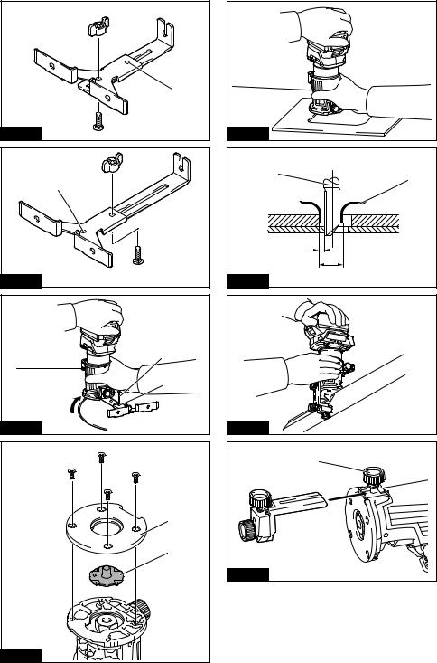
10.Tighten the stopper pole ixing nut. ► Fig.15: 1. Fixing nut
11.Release the ixing lever.
► Fig.16: 1. Fixing lever
ASSEMBLY
 CAUTION: Always be sure that the tool is switched off and the battery cartridge is removed before carrying out any work on the tool.
Installing or removing trimmer bit
NOTICE: Do not tighten the collet nut without inserting the bit. The collet cone may break.
Insert the trimmer bit all the way into the collet cone.
Press the shaft lock and tighten the collet nut with the
wrench or tighten the collet nut securely with the two wrenches. To remove the bit, follow the installation
procedure in reverse.
►Fig.17: 1. Shaft lock 2. Loosen 3. Tighten
4.Wrench 5. Collet nut
►Fig.18: 1. Wrench 2. Loosen 3. Tighten 4. Collet nut
NOTE: The shaft lock may not return to the original
position when you tighten the collet nut at the instal- lation of the trimmer bit. The shaft lock returns to the
original position when you start the tool.
► Fig.19: 1. Shaft lock
Installing or removing the trimmer base
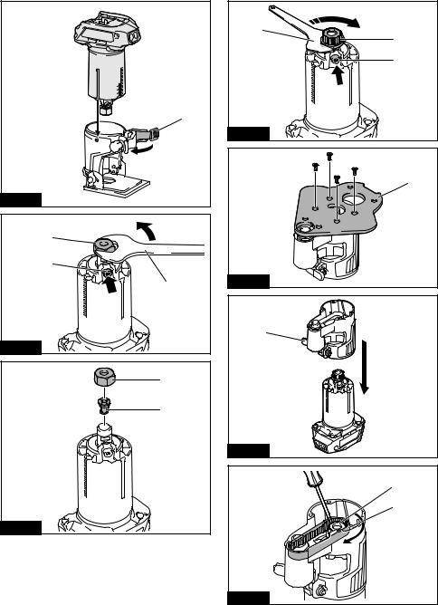
1. Open the lock lever of the trimmer base, then insert the tool into the trimmer base aligning the groove on the tool with the protrusion on the trimmer base.
► Fig.20: 1. Lock lever
16 ENGLISH

NOTE: You can use the trimmer base (resin) as an optional accessory as shown in the igure. When using the trimmer base (resin), loosen or tighten the thumb nut instead of opening or closing the lock lever.
►Fig.21: 1. Thumb nut
2.Close the lock lever.
3.Attach the dust nozzle to the trimmer base, and
then tighten the thumb screw.
►Fig.22: 1. Dust nozzle 2. Thumb screw
►Fig.23
To remove the base, follow the installation procedure in reverse.
 CAUTION: When using the tool with the trimmer base, be sure to install the dust nozzle on the trimmer base.
Installing or removing the tilt base
Optional accessory
1.Open the lock lever of the tilt base, then insert the tool into the tilt base aligning the groove on the tool with
the protrusion on the tilt base.
► Fig.24: 1. Lock lever
2.Close the lock lever.
To remove the base, follow the installation procedure in reverse.
Installing or removing the offset base
Optional accessory
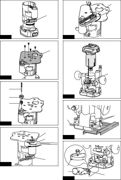
1.Press the shaft lock, then loosen the collet nut.
►Fig.25: 1. Collet nut 2. Shaft lock 3. Wrench
2.Remove the collet nut and the collet cone.
►Fig.26: 1. Collet nut 2. Collet cone
3.Install the pulley on the tool by pressing the shaft
lock and tightening the pulley with the wrench.
► Fig.27: 1. Wrench 2. Pulley 3. Shaft lock
4.Loosen the screws on the base plate, and then
remove the base plate.
► Fig.28: 1. Base plate
5.Open the lock lever of the offset base, then insert the tool into the offset base.
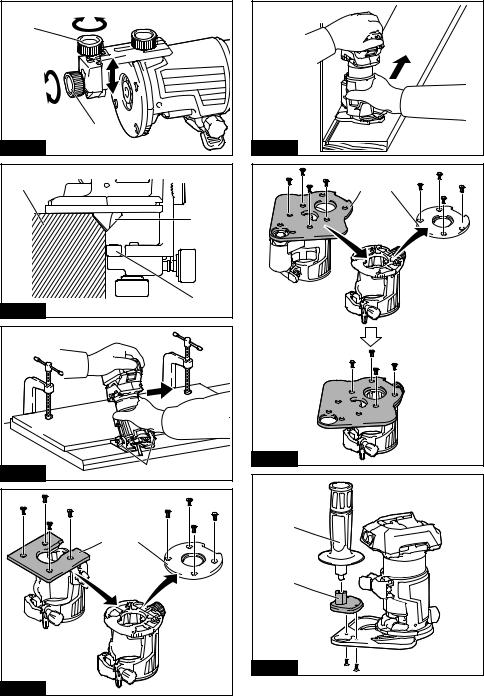
► Fig.29: 1. Lock lever
6.Mount the belt to the pulley by rotating the belt
manually.
► Fig.30: 1. Pulley 2. Belt
7.Close the lock lever.
► Fig.31: 1. Lock lever
8.Attach the base plate by tightening the screws. ► Fig.32: 1. Base plate
9.Insert the collet cone and the trimmer bit into the offset base, and then tighten the collet nut.
► Fig.33: 1. Trimmer bit 2. Collet nut 3. Collet cone
10.Insert the hex wrench into the hole of the offset
base, and then tighten the collet nut with the wrench. ► Fig.34: 1. Collet nut 2. Wrench 3. Hex wrench
To remove the base, follow the installation procedure in reverse.
NOTE: You can also mount the belt to the pulley with- out removing the base plate as shown in the igure.
► Fig.35: 1. Pulley 2. Belt
Installing or removing the plunge base
Optional accessory
1.Open the lock lever of the plunge base, then insert the tool into the plunge base all the way aligning the groove on the tool with the protrusion on the plunge
base.
► Fig.36: 1. Lock lever
2.Close the lock lever.
To remove the base, follow the installation procedure in reverse.
Installing or removing the parallel ruler on the plunge base
Optional accessory
Insert the guide bars into the holes in the plunge base, and then tighten the wing bolts. To remove the ruler, follow the installation procedure in reverse.
► Fig.37: 1. Wing bolt 2. Guide bar
Installing or removing the dust nozzle on the plunge base
Insert the dust nozzle into the plunge base so that the protrusion on the dust nozzle its in the notch in the
plunge base, and then tighten the thumb screw on the dust nozzle. To remove the nozzle, follow the installa-
tion procedure in reverse.
►Fig.38: 1. Protrusion 2. Dust nozzle 3. Thumb screw
►Fig.39
OPERATION
Using the tool with the trimmer base
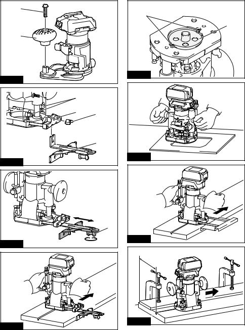
Set the tool base on the workpiece without the trimmer bit making any contact. Turn the tool on and wait until the bit attains full speed. Move the tool forward over the workpiece surface. Keep the tool base lush while
moving the tool.
When cutting the edge, be sure to keep the workpiece surface on the left side of the trimmer bit in the feed
direction.
► Fig.40
17 ENGLISH

NOTE: Before cutting on the actual workpiece, it is recommended to make a sample cut. The proper feed speed depends on the trimmer bit size, the kind of workpiece, and depth of cut. Moving the tool forward too fast may cause a poor quality of cut, or damage to the bit or motor. Moving the tool forward too slowly may burn and mar the cutting surface.
When using the trimmer shoe, the straight guide, or the
trimmer guide, be sure to keep it on the right side in the feed direction. This will help to keep it lush with the side of the workpiece.
► Fig.41: 1. Trimmer bit 2. Workpiece 3. Straight guide
NOTICE: Since excessive cutting may cause overload of the motor or dificulty in controlling
the tool, the depth of cut should not be more than 3 mm at a pass when cutting grooves. When you wish to cut grooves more than 3 mm deep, make several passes with progressively deeper bit settings.
Using the straight guide
Optional accessory
1.Assemble the straight guide with the bolt and the
wing nut.
► Fig.42: 1. Bolt 2. Wing nut
2.Attach the straight guide to the trimmer base with
the clamp screw.
► Fig.43: 1. Clamp screw
3.Loosen the wing nut on the straight guide and adjust the distance between the bit and the straight guide. At the desired distance, tighten the wing nut.
► Fig.44: 1. Wing nut
4. Move the tool with the straight guide lush with the side of the workpiece.
► Fig.45
If the distance (A) between the side of the workpiece and the cutting position is too wide for the straight guide, or if the side of the workpiece is not straight, the
straight guide cannot be used.
In this case, irmly clamp a straight board to the work-
piece and use it as a guide against the trimmer base.
Feed the tool in the direction of the arrow. ► Fig.46
Using the straight guide for circular work
For circular work, assemble the straight guide as shown in the igures. The minimum and maximum radius of circles to be cut (distance between the center of circle and the center of bit) are as follows:
•Minimum: 70 mm
•Maximum: 221 mm
For cutting circles between 70 mm and 121 mm in radius.
► Fig.47: 1. Center hole
For cutting circles between 121 mm and 221 mm in radius.
► Fig.48: 1. Center hole
NOTE: Circles between 172 mm and 186 mm in radius cannot be cut using this guide.
Align the center hole in the straight guide with the cen- ter of the circle to be cut. Drive a nail less than 6 mm
in diameter into the center hole to secure the straight guide. Pivot the tool around the nail in the clockwise direction.
► Fig.49: 1. Nail 2. Center hole
Using the templet guide
Optional accessory
The templet guide allows for repetitive cut with templet patterns by using a templet.
1.Loosen the screws on the base plate, and then remove the base plate from the trimmer base.
2.Place the templet guide on the base, and then
attach the base plate by tightening the screws.
► Fig.50: 1. Base plate 2. Templet guide
3. Place the tool on the templet and move the tool with the templet guide sliding along the side of the
templet.
► Fig.51
NOTE: The actual cut size on the workpiece is slightly different from the templet. The difference is the dis- tance (X) between the trimmer bit and the outside of the templet guide. The distance (X) can be calculated by using the following equation:
Distance (X) = (outside diameter of templet guide - trimmer bit diameter) / 2
►Fig.52: 1. Trimmer bit 2. Templet guide 3. Distance
(X)4. Outside diameter of templet guide
Using the trimmer guide
Optional accessory
The trimmer guide allows for trimming the curved side like veneers for furniture by moving the guide roller along the side of the workpiece.
► Fig.53
1.Loosen the clamp screw, then install the trimmer guide on the trimmer base, and then tighten the clamp
screw.
► Fig.54: 1. Clamp screw
2.Loosen the clamp screw and adjust the distance
between the trimmer bit and the trimmer guide by turn- ing the adjusting screw (1 mm per turn). At the desired
distance, tighten the clamp screw to secure the trimmer guide.
►Fig.55: 1. Adjusting screw 2. Clamp screw
3.Move the tool with the guide roller riding the side of the workpiece.
►Fig.56: 1. Workpiece 2. Bit 3. Guide roller
18 ENGLISH

Using the tool with the tilt base
The tilt base is convenient for chamfering. Loosen the wing screws, then tilt the tool at the desired angle, and then tighten the wing screws.
Firmly clamp a straight board to the workpiece and use
it as a guide against the tilt base. Feed the tool in the direction of the arrow.
► Fig.57: 1. Wing screw
Using the tilt base plate with the trimmer base
To use the trimmer base with a square base plate, remove the base plate from the tilt base, and then
attach it to the trimmer base.
► Fig.58: 1. Tilt base plate 2. Trimmer base plate
Using the tool with the offset base
The offset base is convenient for work in a tight area such as a corner.
► Fig.59
Using the trimmer base with the offset base plate and grip
The offset base plate can also be used with a trimmer base and a grip attachment (optional accessory) for
more stability.
1.Loosen the screws on the base plate, then remove the base plate from the offset base.
► Fig.60: 1. Offset base plate 2. Trimmer base plate
2.Attach the offset base plate to the trimmer base by tightening the screws.
3.Attach the grip attachment and the bar type grip to the offset base plate by tightening the screws.
► Fig.61: 1. Bar type grip 2. Grip attachment
The knob type grip removed from the plunge base can be installed on the offset base instead of the bar type
grip.
► Fig.62: 1. Screw 2. Knob type grip
Using the tool with the plunge base
Always hold the grips irmly with both hands during operation. Operate the tool in the same way as the trimmer base.
Using the straight guide
Optional accessory
1.Install the straight guide to the guide holder by tightening the wing nut. Insert the guide holder into the holes in the plunge base, and then tighten the wing
bolts.
► Fig.63: 1. Wing bolt 2. Guide holder 3. Wing nut
4.Straight guide
2.Loosen the wing nut on the straight guide and adjust the distance between the bit and the straight guide. At the desired distance, tighten the wing nut.
► Fig.64: 1. Wing nut
3. Operate the tool in the same way as the straight guide for the trimmer base.
► Fig.65
Using the templet guide
Optional accessory
1. Loosen the screws on the base and remove them. Place the templet guide on the base, and then tighten
the screws.
► Fig.66: 1. Screw 2. Templet guide
2. Operate the tool in the same way as the templet guide for the trimmer base.
► Fig.67
Using the parallel ruler
The parallel ruler is effectively used for straight cuts when chamfering or grooving. Adjust the distance between the bit and the parallel ruler. At the desired
distance, tighten the wing bolts to secure the parallel
ruler. When cutting, move the tool with the parallel ruler lush with the side of the workpiece.
► Fig.68
If the distance (A) between the side of the workpiece and the cutting position is too wide for the parallel ruler, or if the side of the workpiece is not straight, the parallel
ruler cannot be used.
In this case, irmly clamp a straight board to the work-
piece and use it as a guide against the plunge base.
Feed the tool in the direction of the arrow. ► Fig.69
Changing knob type grip to bar type grip
To install the bar type grip on the plunge base, loosen the screw of the knob type grip, then remove the knob
type grip, and then install the bar type grip by tightening
it.
► Fig.70: 1. Knob type grip 2. Screw 3. Bar type grip
MAINTENANCE
 CAUTION: Always be sure that the tool is switched off and the battery cartridge is removed before attempting to perform inspection or maintenance.
NOTICE: Never use gasoline, benzine, thinner, alcohol or the like. Discoloration, deformation or cracks may result.
To maintain product SAFETY and RELIABILITY, repairs, any other maintenance or adjustment should be performed by Makita Authorized or Factory Service
Centers, always using Makita replacement parts.
19 ENGLISH

OPTIONAL
ACCESSORIES
 CAUTION: These accessories or attachments
are recommended for use with your Makita tool speciied in this manual. The use of any other accessories or attachments might present a risk of injury to persons. Only use accessory or attachment for its stated purpose.
If you need any assistance for more details regard- ing these accessories, ask your local Makita Service Center.
•Straight and groove forming bits
•Edge forming bits
•Laminate trimming bits
•Straight guide assembly
•Trimmer guide assembly
•Trimmer base assembly
•Trimmer base assembly (resin)
•Tilt base assembly
•Plunge base assembly
•Offset base assembly
•Grip attachment
•Templet guide
•Collet cone 6 mm
•Collet cone 6.35 mm (1/4")
•Collet cone 8 mm
•Collet cone 9.53 mm (3/8")
•Wrench 13
•Wrench 22
•Makita genuine battery and charger
NOTE: Some items in the list may be included in the tool package as standard accessories. They may differ from country to country.
Trimmer bits
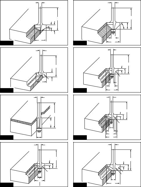
Straight bit ► Fig.71
|
D |
A |
L1 |
L2 |
|
|
|
|
|
20 |
6 |
20 |
50 |
15 |
|
|
|
|
|
20E |
1/4" |
|
|
|
8 |
8 |
8 |
60 |
25 |
|
|
|
|
|
8 |
6 |
|
50 |
18 |
8E |
1/4" |
|
|
|
|
|
|
|
|
6 |
6 |
6 |
50 |
18 |
|
|
|
|
|
6E |
1/4" |
|
|
|
Unit: mm |
|
|
|
|
"U" Grooving bit |
|
|
|
|
► Fig.72 |
|
|
|
|
|
D |
A |
L1 |
L2 |
R |
|
|
|
|
|
|
6 |
6 |
6 |
50 |
18 |
3 |
6E |
1/4" |
|
|
|
|
|
|
|
|
|
|
Unit: mm |
|
|
|
|
|
"V" Grooving bit ► Fig.73
D |
|
|
A |
|
|
|
|
L1 |
|
|
|
L2 |
|
|
|
|
θ |
|
|
|
|||||
1/4" |
|
|
|
20 |
|
|
|
|
50 |
|
|
|
15 |
|
|
|
|
90° |
|
||||||
|
|
|
|
|
|
|
|
|
|
|
|
|
|
|
|
|
|
|
|
|
|
|
|
|
|
Unit: mm |
|
|
|
|
|
|
|
|
|
|
|
|
|
|
|
|
|
|
|
|
|
|
|
|
|
Drill point lush trimming bit |
|
|
|
|
|
|
|
|
|
|
|
|
|||||||||||||
► Fig.74 |
|
|
|
|
|
|
|
|
|
|
|
|
|
|
|
|
|
|
|
|
|||||
|
|
|
|
|
|
|
|
|
|
|
|
|
|
|
|
|
|
|
|
|
|
|
|
|
|
|
|
|
D |
|
|
A |
|
|
L1 |
|
|
|
L2 |
|
|
|
|
L3 |
|||||||
|
|
|
|
|
|
|
|
|
|
|
|
|
|
|
|
|
|
|
|
|
|
|
|
|
|
8 |
|
|
8 |
|
|
|
|
8 |
|
|
|
60 |
|
|
20 |
|
|
|
|
35 |
|||||
|
|
|
|
|
|
|
|
|
|
|
|
|
|
|
|
|
|
|
|
|
|
|
|
|
|
6 |
|
|
6 |
|
|
|
|
|
|
6 |
|
|
|
|
|
|
|
|
18 |
|
|
28 |
|||
6E |
|
1/4" |
|
|
|
|
|
|
|
|
|
|
|
|
|
|
|
|
|
|
|
|
|
||
|
|
|
|
|
|
|
|
|
|
|
|
|
|
|
|
|
|
|
|
|
|
|
|
|
|
Unit: mm |
|
|
|
|
|
|
|
|
|
|
|
|
|
|
|
|
|
|
|
|
|
|
|
|
|
Drill point double lush trimming bit |
|
|
|
|
|
|
|
||||||||||||||||||
► Fig.75 |
|
|
|
|
|
|
|
|
|
|
|
|
|
|
|
|
|
|
|
|
|||||
|
|
|
|
|
|
|
|
|
|
|
|
|
|
|
|
|
|
|
|
|
|||||
|
|
D |
|
A |
|
|
|
L1 |
|
|
L2 |
|
|
L3 |
|
|
L4 |
||||||||
|
|
|
|
|
|
|
|
|
|
|
|
|
|
|
|
|
|
|
|
|
|
|
|
||
8 |
|
8 |
|
|
|
8 |
|
|
|
80 |
|
|
95 |
|
|
|
20 |
|
|
|
25 |
||||
|
|
|
|
|
|
|
|
|
|
|
|
|
|
|
|
|
|
|
|
|
|
|
|||
6 |
|
6 |
|
|
|
|
6 |
|
|
70 |
|
40 |
|
|
12 |
|
|
14 |
|||||||
|
|
|
|
|
|
|
|
|
|
|
|
|
|
|
|
|
|
|
|
|
|
|
|
||
6E |
1/4" |
|
|
|
|
|
|
|
|
|
|
|
|
|
|
|
|
|
|
|
|
|
|||
Unit: mm |
|
|
|
|
|
|
|
|
|
|
|
|
|
|
|
|
|
|
|
|
|
|
|
|
|
Corner rounding bit |
|
|
|
|
|
|
|
|
|
|
|
|
|
|
|
|
|||||||||
► Fig.76 |
|
|
|
|
|
|
|
|
|
|
|
|
|
|
|
|
|
|
|
|
|||||
|
|
|
|
|
|
|
|
|
|
|
|
|
|
|
|
|
|||||||||
|
|
D |
|
A1 |
|
A2 |
L1 |
|
|
L2 |
|
L3 |
|
|
R |
||||||||||
|
|
|
|
|
|
|
|
|
|
|
|
|
|
|
|
|
|
|
|
|
|||||
8R |
|
6 |
|
|
|
25 |
|
|
9 |
48 |
|
|
|
13 |
|
|
5 |
|
|
|
8 |
||||
8RE |
|
1/4" |
|
|
|
|
|
|
|
|
|
|
|
|
|
|
|
|
|
|
|
|
|
|
|
|
|
|
|
|
|
|
|
|
|
|
|
|
|
|
|
|
|
|
|
|
|||||
4R |
|
6 |
|
|
|
20 |
|
|
8 |
45 |
|
|
|
10 |
|
|
4 |
|
|
|
4 |
||||
4RE |
|
1/4" |
|
|
|
|
|
|
|
|
|
|
|
|
|
|
|
|
|
|
|
|
|
|
|
|
|
|
|
|
|
|
|
|
|
|
|
|
|
|
|
|
|
|
|
|
|
|
|
|
|
Unit: mm |
|
|
|
|
|
|
|
|
|
|
|
|
|
|
|
|
|
|
|
|
|
|
|
|
|
Chamfering bit |
|
|
|
|
|
|
|
|
|
|
|
|
|
|
|
|
|
|
|||||||
► Fig.77 |
|
|
|
|
|
|
|
|
|
|
|
|
|
|
|
|
|
|
|
|
|||||
|
|
|
|
|
|
|
|
|
|
|
|
|
|
|
|
|
|
||||||||
D |
|
A |
|
|
L1 |
|
|
L2 |
|
|
|
L3 |
|
|
|
|
θ |
||||||||
6 |
|
|
23 |
|
|
|
46 |
|
|
11 |
|
|
|
|
6 |
|
|
|
|
|
30° |
||||
6 |
|
|
20 |
|
|
|
50 |
|
|
13 |
|
|
|
|
5 |
|
|
|
|
|
45° |
||||
|
|
|
|
|
|
|
|
|
|
|
|
|
|
|
|
|
|
|
|
|
|
||||
6 |
|
|
20 |
|
|
|
49 |
|
|
14 |
|
|
|
|
2 |
|
|
|
|
|
60° |
||||
Unit: mm |
|
|
|
|
|
|
|
|
|
|
|
|
|
|
|
|
|
|
|
|
|
|
|
|
|
Cove beading bit |
|
|
|
|
|
|
|
|
|
|
|
|
|
|
|
|
|
|
|||||||
► Fig.78 |
|
|
|
|
|
|
|
|
|
|
|
|
|
|
|
|
|
|
|
|
|||||
|
|
|
|
|
|
|
|
|
|
|
|
|
|
|
|
|
|
|
|
|
|||||
D |
|
|
A |
|
|
|
|
L1 |
|
|
|
L2 |
|
|
|
|
R |
|
|
|
|||||
|
|
|
|
|
|
|
|
|
|
|
|
|
|
|
|
|
|
|
|
|
|||||
6 |
|
|
|
20 |
|
|
|
|
43 |
|
|
|
8 |
|
|
|
|
4 |
|
|
|
|
|||
6 |
|
|
|
25 |
|
|
|
|
48 |
|
|
|
13 |
|
|
|
|
8 |
|
|
|
|
|||
|
|
|
|
|
|
|
|
|
|
|
|
|
|
|
|
|
|
|
|
|
|
|
|
|
|
Unit: mm |
|
|
|
|
|
|
|
|
|
|
|
|
|
|
|
|
|
|
|
|
|
|
|
|
|
Ball bearing lush trimming bit |
|
|
|
|
|
|
|
|
|
|
|
|
|||||||||||||
► Fig.79 |
|
|
|
|
|
|
|
|
|
|
|
|
|
|
|
|
|
|
|
|
|||||
|
|
|
|
|
|
|
|
|
|
|
|
|
|
|
|
|
|
|
|
|
|||||
D |
|
|
|
|
A |
|
|
|
|
L1 |
|
|
|
|
|
|
L2 |
|
|
|
|||||
|
|
|
|
|
|
|
|
|
|
|
|
|
|
|
|
|
|
|
|
|
|||||
6 |
|
|
|
|
|
|
|
10 |
|
|
|
|
50 |
|
|
|
|
|
|
20 |
|||||
1/4" |
|
|
|
|
|
|
|
|
|
|
|
|
|
|
|
|
|
|
|
|
|
|
|
|
|
|
|
|
|
|
|
|
|
|
|
|
|
|
|
|
|
|
|
|
|
|
|
|
|
|
|
Unit: mm |
|
|
|
|
|
|
|
|
|
|
|
|
|
|
|
|
|
|
|
|
|
|
|
|
|
20 ENGLISH
Ball bearing corner rounding bit ► Fig.80
D |
|
A1 |
|
|
A2 |
|
|
|
L1 |
|
|
L2 |
|
L3 |
|
|
R |
|||||||||
6 |
|
|
15 |
|
|
|
8 |
|
|
37 |
|
|
|
7 |
|
|
|
3.5 |
|
|
3 |
|||||
|
|
|
|
|
|
|
|
|
|
|
|
|
|
|
|
|
|
|
|
|
|
|
|
|
|
|
6 |
|
|
21 |
|
|
|
|
|
40 |
|
|
10 |
|
|
|
|
|
|
|
6 |
||||||
1/4" |
|
|
|
|
|
|
|
|
|
|
|
|
|
|
|
|
|
|
|
|
|
|
|
|
|
|
|
|
|
|
|
|
|
|
|
|
|
|
|
|
|
|
|
|
|
|
|
|
|
|
|
|
|
Unit: mm |
|
|
|
|
|
|
|
|
|
|
|
|
|
|
|
|
|
|
|
|
|
|
||||
Ball bearing chamfering bit |
|
|
|
|
|
|
|
|
|
|
|
|
|
|||||||||||||
► Fig.81 |
|
|
|
|
|
|
|
|
|
|
|
|
|
|
|
|
|
|
|
|
|
|
||||
|
|
|
|
|
|
|
|
|
|
|
|
|
|
|
|
|
|
|
|
|
|
|
|
|||
D |
|
|
A1 |
|
|
|
A2 |
|
|
L1 |
|
|
|
L2 |
|
|
|
|
θ |
|||||||
6 |
|
|
|
|
26 |
|
8 |
|
|
|
|
42 |
|
|
|
12 |
|
|
45° |
|||||||
1/4" |
|
|
|
|
|
|
|
|
|
|
|
|
|
|
|
|
|
|
|
|
|
|
|
|
|
|
|
|
|
|
|
|
|
|
|
|
|
|
|
|
|
|
|
|
|
|
|
|
|
|
|||
6 |
|
|
|
20 |
|
|
|
|
|
|
|
|
41 |
|
|
|
11 |
|
|
|
|
60° |
||||
Unit: mm |
|
|
|
|
|
|
|
|
|
|
|
|
|
|
|
|
|
|
|
|
|
|
||||
Ball bearing beading bit |
|
|
|
|
|
|
|
|
|
|
|
|
|
|
||||||||||||
► Fig.82 |
|
|
|
|
|
|
|
|
|
|
|
|
|
|
|
|
|
|
|
|
|
|
||||
|
|
|
|
|
|
|
|
|
|
|
|
|
|
|
|
|
|
|
|
|
|
|||||
D |
|
A1 |
|
A2 |
|
A3 |
|
|
L1 |
|
|
L2 |
|
L3 |
|
|
|
R |
||||||||
|
|
|
|
|
|
|
|
|
|
|
|
|
|
|
|
|
|
|
|
|
|
|||||
6 |
|
20 |
|
12 |
|
8 |
|
|
40 |
|
|
10 |
|
|
5.5 |
|
|
|
4 |
|||||||
6 |
|
26 |
|
|
|
|
|
|
|
|
42 |
|
|
12 |
|
|
4.5 |
|
|
|
7 |
|||||
|
|
|
|
|
|
|
|
|
|
|
|
|
|
|
|
|
|
|
|
|
|
|
|
|
||
Unit: mm |
|
|
|
|
|
|
|
|
|
|
|
|
|
|
|
|
|
|
|
|
|
|
||||
Ball bearing cove beading bit |
|
|
|
|
|
|
|
|
|
|
|
|
|
|||||||||||||
► Fig.83 |
|
|
|
|
|
|
|
|
|
|
|
|
|
|
|
|
|
|
|
|
|
|
||||
|
|
|
|
|
|
|
|
|
|
|
|
|
|
|
|
|
|
|||||||||
D |
|
A1 |
A2 |
A3 |
A4 |
|
|
L1 |
|
L2 |
|
|
L3 |
|
|
|
R |
|||||||||
|
|
|
|
|
|
|
|
|
|
|
|
|
|
|
|
|
||||||||||
6 |
|
20 |
|
18 |
|
12 |
|
8 |
|
40 |
|
10 |
|
|
5.5 |
|
|
|
3 |
|||||||
6 |
|
26 |
|
22 |
|
|
|
|
|
|
|
42 |
|
12 |
|
|
5 |
|
|
|
|
5 |
||||
|
|
|
|
|
|
|
|
|
|
|
|
|
|
|
|
|
|
|
|
|
|
|
|
|||
Unit: mm |
|
|
|
|
|
|
|
|
|
|
|
|
|
|
|
|
|
|
|
|
|
|
||||
Ball bearing roman ogee bit |
|
|
|
|
|
|
|
|
|
|
|
|
|
|||||||||||||
► Fig.84 |
|
|
|
|
|
|
|
|
|
|
|
|
|
|
|
|
|
|
|
|
|
|
||||
|
|
|
|
|
|
|
|
|
|
|
|
|
|
|
|
|
|
|
||||||||
D |
|
A1 |
|
A2 |
|
L1 |
|
|
L2 |
|
|
L3 |
|
R1 |
|
|
|
R2 |
||||||||
6 |
|
20 |
|
8 |
|
40 |
|
|
|
10 |
|
|
4.5 |
|
|
2.5 |
|
|
|
4.5 |
||||||
|
|
|
|
|
|
|
|
|
|
|
|
|
|
|
|
|
|
|
|
|
|
|||||
6 |
|
26 |
|
|
|
|
42 |
|
|
|
12 |
|
|
|
|
|
|
3 |
|
|
|
6 |
||||
Unit: mm
21 ENGLISH

SVENSKA (Originalinstruktioner)
SPECIFIKATIONER
Modell: |
DRT50 |
|
|
Spännhylschuckens kapacitet |
6 mm, 8 mm, 1/4″ eller 3/8″ |
Hastighet utan belastning |
10 000 - 30 000 min-1 |
Total längd |
226 mm |
Märkspänning |
18 V likström |
Standardbatterikassett |
BL1815N / BL1820 / BL1820B / BL1830 / BL1830B / BL1840 / |
|
BL1840B / BL1850 / BL1850B / BL1860B |
Nettovikt |
1,8 - 2,1 kg |
|
|
•På grund av vårt pågående program för forskning och utveckling kan dessa speciikationer ändras utan föregå- ende meddelande.
•Speciikationer och batterikassett kan variera mellan olika länder.
•Vikten kan variera beroende på tillbehören, inklusive batterikassett. Den lättaste och den tyngsta kombinatio- nen enligt EPTA-procedur 01/2014 visas i tabellen.
Avsedd användning
Verktyget är avsett för trimning och proilering av trä, plast och liknande material.
Buller
Den normala bullernivån för A-belastning är bestämd
enligt EN60745:
Ljudtrycksnivå (LpA) : 78 dB (A) Mättolerans (K): 3 dB (A)

 VARNING: Använd hörselskydd.
Vibration
Det totala vibrationsvärdet (treaxlad vektorsumma)
bestämt enligt EN60745:
Arbetsläge: rotation utan belastning Vibrationsemission (ah) : 2,5 m/s2 eller lägre Mättolerans (K): 1,5 m/s2
Arbetsläge: spårfräsning i MDF Vibrationsemission (ah) : 4,5 m/s2 Mättolerans (K): 1,5 m/s2
OBS: Det deklarerade vibrationsemissionsvärdet har
uppmätts i enlighet med standardtestmetoden och kan användas för att jämföra en maskin med en annan.
OBS: Det deklarerade vibrationsemissionsvärdet kan också användas i en preliminär bedömning av exponering för vibration.
 VARNING: Viberationsemissionen under faktisk användning av maskinen kan skilja sig från det deklarerade emissionsvärdet, beroende på hur maskinen används.
 VARNING: Var noga med att identiiera säkerhets-
åtgärder för att skydda användaren, vilka är grundade på en uppskattning av graden av exponering för vibra- tioner under de faktiska användningsförhållandena, (ta, förutom avtryckartiden, med alla delar av användarcy- keln i beräkningen, som till exempel tiden då maskinen är avstängd och när den går på tomgång).
EG-försäkran om överensstämmelse
Gäller endast inom EU
EG-försäkran om överensstämmelse inkluderas som bilaga A till denna bruksanvisning.
SÄKERHETSVARNINGAR
Allmänna säkerhetsvarningar för maskiner
 VARNING: Läs alla säkerhetsvarningar, anvisningar, illustrationer och speciikationer som medföljer det här maskinen. Underlåtenhet att följa
instruktionerna kan leda till elstötar, brand och/eller allvarliga personskador.
Spara alla varningar och instruk-
tioner för framtida referens.
Termen ”maskin” som anges i varningarna hänvisar till din eldrivna maskin (sladdansluten) eller batteridrivna maskin (sladdlös).
Säkerhetsvarningar för batteridriven kantfräs
1.Håll i maskinens isolerade greppytor eftersom kapmaskinen kan komma i kontakt med dolda
kablar. Om verktyget kommer i kontakt med en strömförande ledning blir dess metalldelar ström- förande och kan ge operatören en elektrisk stöt.
2.Använd tvingar eller liknande för att säkra och stödja arbetsstycket på ett stabilt underlag. Att hålla
arbetsstycket i händerna eller mot kroppen ger inte tillräckligt stöd, och du riskerar då att förlora kontrollen.
3.Använd hörselskydd vid längre tids användning.
4.Iaktta försiktighet vid hantering av fräshuvuden.
22 SVENSKA

5.Kontrollera att fräshuvudet inte är sprucket eller skadat före användning. Byt omedelbart ut ett skadat eller sprucket fräshuvud.
6.Undvik att såga i spik. Kontrollera arbetsstycket och ta bort alla spikar före arbetet påbörjas.
7.Håll verktyget i ett fast grepp.
8.Håll händerna på behörigt avstånd från roterande delar.
9.Se till att fräshuvudet inte kommer i kontakt med arbetsstycket innan strömbrytaren slagits på.
10.Låt verktyget vara igång en stund innan det används på arbetsstycket. Kontrollera att det inte förekommer vibrationer eller kast som indikerar att fräshuvudet monterats felaktigt.
11.Kontrollera fräshuvudets rotationsoch matningsriktning.
12.Lämna inte verktyget igång. Använd endast verktyget när du håller det i händerna.
13.Stäng alltid av verktyget och vänta tills fräshuvudet har stannat helt innan du avlägsnar verktyget från arbetsstycket.
14.Rör inte vid fräshuvudet omedelbart efter avslutat arbete. Det kan vara extremt varmt och orsaka brännskador.
15.Iaktta försiktighet med förtunningsmedel, bensin, olja eller liknande på verktygsfästet som vid. Överdriven användning kan orsaka sprickor i verktygsfästet.
16.Använd fräshuvuden med en skaftdiameter som passar verktygets hastighet.
17.Vissa material kan innehålla giftiga kemikalier. Se till att du inte andas in dammet från kemikalier eller får något på huden. Följ anvisningarna i leverantörens materialsäkerhetsblad.
18.Använd alltid dammask eller andningsrespirator som är anpassad efter det material du arbetar med och de förhållanden du arbetar under.
SPARA DESSA ANVISNINGAR.
 VARNING: GLÖM INTE att också fortsättningsvis strikt följa säkerhetsanvisningarna för maskinen även efter att du blivit van att använda den. Vid FELAKTIG HANTERING av maskinen eller om inte säkerhetsanvisningarna i denna bruksanvisning följs kan följden bli allvarliga personskador.
5.Kortslut inte batterikassetten.
(1)Rör inte vid polerna med något strömförande material.
(2)Undvik att förvara batterikassetten tillsammans med andra metallobjekt som t.ex. spikar, mynt o.s.v.
(3)Skydda batteriet mot vatten och regn.
En batterikortslutning kan orsaka ett stort strömlöde, överhettning, brand och
maskinhaveri.
6.Förvara inte maskinen och batterikassetten på platser där temperaturen kan nå eller överstiga 50 °C.
7.Bränn inte upp batterikassetten även om den är svårt skadad eller helt utsliten. Batterikassetten kan explodera i öppen eld.
8.Var försiktig så att du inte råkar tappa batteriet och utsätt det inte för stötar.
9.Använd inte ett skadat batteri.
10.De medföljande litiumjonbatterierna är föremål för kraven i gällande lagstiftning för farligt
gods.
För kommersiella transporter (av t.ex. tredje parter som speditionsirmor) måste de särskilda trans- portkrav som anges på emballaget och etiketter
iakttas.
För att förbereda den produkt som ska avsändas krävs att du konsulterar en expert på riskmaterial. Var också uppmärksam på att det i ditt land kan innas ytterligare föreskrifter att följa.
Tejpa över eller maskera blottade kontakter och packa batteriet på sådant sätt att det inte kan röra sig fritt i förpackningen.
11.Följ lokala föreskrifter beträffande avfallshantering av batteriet.
12.Använd endast batterierna med de produkter som speciicerats av Makita. Att använda bat- terierna med ej godkända produkter kan leda till brand, överdriven värme, explosion eller utläck- ande elektrolyt.
SPARA DESSA ANVISNINGAR.
 FÖRSIKTIGT: Använda endast äkta Makitabatterier. Användning av oäkta Makita-batterier eller
batterier som har manipulerats kan leda till person- och utrustningsskador eller till att batteriet fattar eld. Det upphäver också Makitas garanti för verktyget och
laddaren.
Viktiga säkerhetsanvisningar för batterikassetten
1.Innan batterikassetten används ska alla instruktioner och varningsmärken på (1) batteriladdaren, (2) batteriet och (3) produkten läsas.
2.Montera inte isär batterikassetten.
3.Om drifttiden blivit avsevärt kortare ska användningen avbrytas omedelbart. Det kan uppstå överhettning, brännskador och t o m en explosion.
4.Om du får elektrolyt i ögonen ska de sköljas
med rent vatten och läkare uppsökas omedelbart. Det inns risk för att synen förloras.
Tips för att uppnå batteriets maximala livslängd
1.Ladda batterikassetten innan den är helt urladdad. Stanna alltid maskinen och ladda batterikassetten när du märker att maskinen blir svagare.
2.Ladda aldrig en fulladdad batterikassett. Överladdning förkortar batteriets livslängd.
3.Ladda batterikassetten vid en rumstemperatur på 10 °C - 40 °C. Låt en varm batterikassett svalna innan den laddas.
4.Ladda batterikassetten om du inte har använt den på länge (mer än sex månader).
23 SVENSKA

FUNKTIONSBESKRIVNING
 FÖRSIKTIGT: Se alltid till att maskinen är avstängd och batterikassetten borttagen innan du justerar maskinen eller kontrollerar dess funktioner.
Montera eller demontera batterikassetten
 FÖRSIKTIGT: Stäng alltid av maskinen innan du monterar eller tar bort batterikassetten.
 FÖRSIKTIGT: Håll stadigt i maskinen och
batterikassetten när du monterar eller tar bort batterikassetten. I annat fall kan det leda till att de glider ur dina händer och orsakar skada på maskinen
och batterikassetten samt personskada.
► Fig.1: 1. Röd indikator 2. Knapp 3. Batterikassett
Ta bort batterikassetten genom att skjuta ner knap- pen på kassettens framsida samtidigt som du drar ut
batterikassetten.
Sätt i batterikassetten genom att rikta in tungan på batterikassetten mot spåret i höljet och skjut den på plats. Tryck in batterikassetten ordentligt tills den låser fast med ett klick. Om du kan se den röda indikatorn på knappens ovansida är den inte låst ordentligt.
 FÖRSIKTIGT: Sätt alltid i batterikassetten
helt tills den röda indikatorn inte längre syns.
I annat fall kan den oväntat falla ur maskinen och skada dig eller någon annan.
 FÖRSIKTIGT: Montera inte batterikassetten med våld. Om kassetten inte lätt glider på plats är den felinsatt.
Indikerar kvarvarande batterikapacitet
Endast för batterikassetter med indikator
► Fig.2: 1. Indikatorlampor 2. Kontrollknapp
Tryck på kontrollknappen på batterikassetten för att se kvarvarande batterikapacitet. Indikatorlamporna lyser i ett par sekunder.
|
Indikatorlampor |
Kvarvarande |
|
|
kapacitet |
Upplyst |
Av |
Blinkar |
|
|
75% till 100% |
|
|
50% till 75% |
|
|
25% till 50% |
|
|
0% till 25% |
|
|
Ladda |
|
|
batteriet. |
|
|
Batteriet kan |
|
|
ha skadats. |
OBS: Beroende på användningsförhållanden och den omgivande temperaturen kan indikationen skilja sig lätt från den faktiska batterikapaciteten.
Skyddssystem för maskinen/ batteriet
Verktyget är utrustat med ett skyddssystem för verkty-
get/batteriet. Detta system bryter automatiskt strömmen till motorn för att förlänga verktygets och batteriets
livslängd. Verktyget stoppar automatiskt under använd- ningen om verktyget eller batteriet hamnar i en av föl- jande situationer:
Överbelastningsskydd
Om batteriet används på ett sätt som gör att det drar
onormalt mycket ström kan det stoppas automatiskt utan någon varning. När detta sker stänger du av verk- tyget och upphör med arbetet som gjorde att verktyget överbelastades. Starta därefter verktyget igen.
Överhettningsskydd
När verktyget eller batteriet överhettas stoppas det automatiskt och lampan börjar blinka. I sådant fall ska du låta verktyget och batteriet svalna innan du startar
verktyget igen.
Överurladdningsskydd
När batteriets kapacitet är otillräcklig stoppar maskinen automatiskt. I sådant fall ska batteriet tas ur maskinen
och laddas.
Avtryckarens funktion
Tryck på lås-/upplåsningsknappen för att starta maski- nen. Maskinen går till standby-läge. För att starta maskinen i standby-läge, tryck på start-/stoppknap- pen. Tryck en gång till på start-/stoppknappen för att stoppa maskinen. Maskinen går till standby-läge. För att stänga av maskinen i standby-läge, tryck på lås-/ upplåsningsknappen.
► Fig.3: 1. Lås-/upplåsningsknapp 2. Start-/ stoppknapp
OBS: Om maskinen lämnas i 10 sekunder utan några åtgärder i standbyläge, stängs maskinen automatiskt
av och lampan släcks.
OBS: Du kan även stoppa och stänga av maskinen genom att trycka på lås-/upplåsningsknappen när
maskinen används.
Tända frontlampan
 FÖRSIKTIGT: Titta inte in i ljuset eller direkt i ljuskällan.
Tryck på lås-/upplåsningsknappen för att släcka lam- pan. Tryck på lås-/upplåsningsknappen igen för att
tända lampan.
OBSERVERA: Lampan blinkar när maskinen är överhettad. Låt maskinen svalna fullständigt innan den används igen.
24 SVENSKA

OBS: Använd en torr trasa för att torka bort smuts från lampglaset. Var försiktig så att inte lampglaset repas eftersom ljuset då kan bli svagare.
Ratt för hastighetsinställning
Maskinens rotationshastighet kan ändras genom att vrida på ratten för hastighetsinställning. Tabellen nedan
visar rattens nummer och motsvarande hastighet.
► Fig.4: 1. Ratt för hastighetsinställning
Nummer |
Hastighet |
|
|
1 |
10 000 min-1 |
2 |
15 000 min-1 |
3 |
20 000 min-1 |
4 |
25 000 min-1 |
5 |
30 000 min-1 |
OBSERVERA: Om maskinen används oavbrutet på låg hastighet under lång tid överbelastas motorn, vilket leder till funktionsfel på maskinen.
OBSERVERA: Vid byte på hastighetsratten från ”5” till ”1”, vrid ratten moturs. Vrid inte ratten medurs med våld.
Elektronisk funktion
Maskinen är utrustad med elektroniska funktioner för enkel användning.
•Konstant hastighetskontroll Hastighetskontrollfunktionen ger en konstant rota- tionshastighet oavsett belastningsförhållanden.
•Mjukstart
Mjukstartsfunktionen minimerar ryck vid uppstar- ten och gör att maskinen får en mjuk start.
Ställa in kapningsdjup
Justera kapningsdjupet genom att lossa låsspaken och lytta maskinens bottenplatta uppåt eller nedåt genom att vrida på inställningsskruven. Dra åt låsspaken ordentligt efter justeringen. ► Fig.5: 1. Låsspak 2. Inställningsskruv
OBSERVERA: Om maskinen inte är fäst när låsspaken är stängd, dra åt insexmuttern och stäng därefter låsspaken.
► Fig.6: 1. Insexmutter
Ställa in kapningsdjup med den sänkbara bottenplattan
Extra tillbehör
1.Placera verktyget på ett plant underlag.
2.Välj djupanslagsskruven genom att vrida på djupanslagsplattan.
► Fig.7: 1. Djupanslagsskruv 2. Djupanslagsplatta
3.Lossa på stoppstångens fästmutter, dra ut stopp- stången samtidigt som du håller matningsknappen
nedtryckt.
►Fig.8: 1. Stoppstång 2. Fästmutter
3.Matningsknapp
4. Tryck ner maskinen tills fräshuvudets spets vidrör den plana ytan och vrid därefter ixerspaken för att
säkra maskinen.
► Fig.9: 1. Fixerspak 2. Fräshuvud
5.Tryck ner stoppstången och matningsknappen samtidigt tills den nuddar djupanslagsskruven.
►Fig.10: 1. Stoppstång 2. Djupanslagsskruv
3.Matningsknapp
6.Skjut pekaren för fräsdjup så att pekaren visar ”0” på skalan.
►Fig.11: 1. Pekare för fräsdjup
7.Ställ inkapningsdjupet genom att dra ut stopp- stången samtidigt som du håller matningsknappen
nedtryckt.
► Fig.12: 1. Stoppstång 2. Matningsknapp
8. För att utföra en ininställning av kapningsdjupet, vrid på stoppstångens ratt tills den visar ”0”.
► Fig.13: 1. Ratt
9.Vrid på stoppstångens huvud för att erhålla önskat djup. Vrid på huvudet moturs för att öka djupet. Vrid på huvudet medurs för att minska djupet.
►Fig.14: 1. Stoppstångens huvud
10.Dra åt stoppstångens fästmutter.
►Fig.15: 1. Fästmutter
11.Släpp ixerspaken.
►Fig.16: 1. Fixerspak
MONTERING
 FÖRSIKTIGT: Se alltid till att maskinen är avstängd och batterikassetten borttagen innan du underhåller maskinen.
Montera eller demontera fräshuvud
OBSERVERA: Dra inte åt hylsmuttern utan att ha monterat fräshuvudet. Spännhylsan kan gå
sönder.
För in fräshuvudet hela vägen in i spännhylsan. Tryck in spindellåset och dra åt spännhylsmuttern med nyckeln eller dra åt hylsmuttern ordentligt med de två nycklarna. Följ monteringsförfarandet i omvänd ordning för att avlägsna fräsverktyget.
►Fig.17: 1. Spindellås 2. Lossa 3. Dra åt 4. Nyckel
5.Hylsmutter
►Fig.18: 1. Nyckel 2. Lossa 3. Dra åt 4. Hylsmutter
OBS: Spindellåset kanske inte går tillbaka till ursprungsläge när du drar åt hylsmuttern vid instal- lation av fräshuvud. Spindellåset går tillbaka till
ursprungsläge när du startar maskinen.
► Fig.19: 1. Spindellås
25 SVENSKA

Montera eller demontera kantfräsens bottenplatta
1. Öppna låsspaken på kantfräsens bottenplatta, för in verktyget i kantfräsens bottenplatta och rikta in spåren i verktyget med den utskjutande delen på kant- fräsens bottenplatta.
► Fig.20: 1. Låsspak
OBS: Du kan använda bottenplattan (harts) som valfritt tillbehör enligt vad som visas på bilden. När bottenplattan (harts) används, lossa eller spänn åt den lättrade muttern istället för att öppna eller stänga låsspärren.
►Fig.21: 1. Lättrad mutter
2.Stäng låsspaken.
3.Fäst dammunstycket på kantfräsens bottenplatta och dra åt tumskruven.
►Fig.22: 1. Dammunstycke 2. Tumskruv
►Fig.23
Ta bort bottenplattan genom att följa monteringsproce- duren i omvänd ordning.
 FÖRSIKTIGT: När du använder maskinen med kantfräsens bottenplatta ska du alltid montera dammunstycket på kantfräsens bottenplatta.
Montera eller demontera den fällbara bottenplattan
Extra tillbehör
1.Öppna låsspaken på den fällbara bottenplattan, för in verktyget i den fällbara bottenplattan och rikta in spåren i verktyget med den utskjutande delen på den fällbara bottenplattan.
►Fig.24: 1. Låsspak
2.Stäng låsspaken.
Ta bort bottenplattan genom att följa monteringsproce- duren i omvänd ordning.
Montera eller demontera distansbottenplattan
Extra tillbehör
1.Tryck på spindellåset och lossa därefter
hylsmuttern.
► Fig.25: 1. Hylsmutter 2. Spindellås 3. Nyckel
2.Ta bort hylsmuttern och spännhylsan.
►Fig.26: 1. Hylsmutter 2. Spännhylsa
3.Montera drivhjulet på maskinen genom att trycka på spindellåset och dra åt drivhjulet med en nyckel.
►Fig.27: 1. Nyckel 2. Drivhjul 3. Spindellås
4.Lossa skruven på bottenplattan och ta bort bottenplattan.
►Fig.28: 1. Bottenplatta
5.Öppna distansbottenplattans låsspak och sätt därefter i verktyget i distansbottenplattan.
►Fig.29: 1. Låsspak
6.Montera remmen på drivhjulet genom att snurra
remmen manuellt.
► Fig.30: 1. Drivhjul 2. Rem
7.Stäng låsspaken.
►Fig.31: 1. Låsspak
8.Fäst basplattan genom att dra åt skruvarna.
►Fig.32: 1. Bottenplatta
9.För in spännhylsan och fräshuvudet i distansbot- tenplattan och dra åt hylsmuttern.
►Fig.33: 1. Fräshuvud 2. Hylsmutter 3. Spännhylsa
10.Sätt in insexnyckeln i distansbottenplattans hål och dra åt hylsmuttern med nyckeln.
►Fig.34: 1. Hylsmutter 2. Nyckel 3. Insexnyckel
Ta bort bottenplattan genom att följa monteringsproce- duren i omvänd ordning.
OBS: Du kan även montera remmen på drivhjulet utan att ta bort basplattan enligt iguren.
► Fig.35: 1. Drivhjul 2. Rem
Montera eller demontera den sänkbara bottenplattan
Extra tillbehör
1.Öppna låsspaken på den sänkbara bottenplattan, för in verktyget hela vägen i den sänkbara bottenplattan och rikta in spåren i verktyget med den utskjutande delen på den sänkbara bottenplattan.
►Fig.36: 1. Låsspak
2.Stäng låsspaken.
Ta bort bottenplattan genom att följa monteringsproce- duren i omvänd ordning.
Montera eller demontera parallellinjalen på den sänkbara bottenplattan
Extra tillbehör
Sätt i anhållsstängerna i hålen på den sänkbara botten- plattan och dra åt vingbultarna. Ta bort linjalen genom att följa monteringsproceduren i omvänd ordning.
► Fig.37: 1. Vingbult 2. Svärd
Montera eller demontera dammunstycket på den sänkbara bottenplattan
Sätt i dammunstycket på den sänkbara bottenplattan så att den utskjutande delen på dammunstycket passar in i skåran i den sänkbara bottenplattan och dra därefter åt tumskruven på dammunstycket. Ta bort munstycket genom att följa monteringsproceduren i omvänd
ordning.
►Fig.38: 1. Utsprång 2. Dammunstycke 3. Tumskruv
►Fig.39
26 SVENSKA

ANVÄNDNING
Använda maskinen med kantfräsens bottenplatta
Placera bottenplattan på arbetsstycket utan att fräs-
huvudet kommer i kontakt med det. Starta maskinen och vänta tills fräsverktyget uppnått full hastighet. För maskinen framåt över arbetsstyckets yta. Håll botten- plattan jäms med arbetsstycket när du lyttar maskinen. Vid fräsning av kanten ska arbetsstyckets yta beinna sig på vänster sida av fräshuvudet i matningsriktningen.
► Fig.40
OBS: Innan du fräser på arbetsstycket rekommende- ras att göra en provfräsning. Lämplig matningshastig- het beror på fräsverktygets dimension, typ av arbets- stycke och fräsdjup. Om maskinen matas framåt för snabbt kan den frästa ytan få en dålig inish, eller så kan fräsverktyget eller motorn skadas. Om maskinen förs framåt för långsamt kan arbetsstycket bli bränt
och ytan skadas.
När fräsanslaget, parallellanslaget eller rullanslaget används, skall du se till att hålla anslaget på den högra sidan i matningsriktningen. Det blir då lättare att hålla
anslaget plant mot arbetsstyckets sida.
►Fig.41: 1. Fräshuvud 2. Arbetsstycke
3.Parallellanslag
OBSERVERA: Eftersom en för kraftig fräsning kan orsaka överbelastning av motorn eller svårigheter att kontrollera maskinen, bör fräsdjupet inte
vara mer än 3 mm per gång vid spårfräsning. Gör lera fräsningar med en gradvis ökande inställning av fräsdjupet när du vill fräsa spår som är djupare än 3
mm.
Använda parallellanslag
Extra tillbehör
1.Fäst parallellanslaget med bulten och vingmuttern. ► Fig.42: 1. Bult 2. Vingmutter
2.Montera parallellanslaget på kantfräsens botten- platta med låsskruven.
► Fig.43: 1. Spännskruv
3.Lossa vingmuttern på parallellanslaget och justera avståndet mellan fräsverktyget och parallellanslaget. Fäst vingmuttern vid önskat avstånd.
►Fig.44: 1. Vingmutter
4.För verktyget med parallellanslaget plant mot arbetsstyckets sida.
►Fig.45
Om avståndet (A) mellan arbetsstyckets sida och fräslinjen är för stort för parallellanslaget, eller om
arbetsstyckets sida inte är rak, kan parallellanslaget
inte användas.
Spänn i sådant fall fast en träskiva med rak kant på arbetsstycket och använd den som anslag mot kantfrä-
sens bottenplatta. För maskinen i pilens riktning.
► Fig.46
Använda ett parallellanslag för cirkelarbete
Montera parallellanslaget för cirkelarbete enligt igu- rerna. Minsta och maximala radie hos cirklar som ska fräsas (avståndet mellan cirkelns mittpunkt och fräs- verktygets mittpunkt) är enligt följande:
•Min: 70 mm
•Max: 221 mm
För fräsning av cirklar med en radie mellan 70 mm
och 121 mm.
► Fig.47: 1. Mitthål
För fräsning av cirklar med en radie mellan 121 mm
och 221 mm.
► Fig.48: 1. Mitthål
OBS: Cirklar med en radie mellan 172 mm och 186 mm kan inte fräsas med detta anslag.
Rikta in mitthålet på parallellanslaget efter mittpunkten på den cirkel som ska fräsas. Slå i en spik som är min- dre än 6 mm i diameter i mitthålet för att fästa parallel-
lanslaget. Sväng maskinen medurs runt spiken.
► Fig.49: 1. Spik 2. Mitthål
Använda mallanslag
Extra tillbehör
Med ett mallanslag kan man upprepa fräsningen efter mallmönster med en mall.
1.Lossa skruven på bottenplattan och ta bort botten- plattan från kantfräsens bottenplatta.
2.Placera mallanslaget på bottenplattan och fäst därefter bottenplattan genom att dra åt skruvarna.
►Fig.50: 1. Bottenplatta 2. Mallanslag
3.Placera verktyget på mallen och för verktyget med mallanslaget glidande utefter mallens sida.
►Fig.51
OBS: Den faktiska fräsdimensionen på arbetsstycket skiljer sig lite från mallen. Skillnaden är avståndet
(X) mellan fräshuvudet och mallanslagets utsida. Avståndet (X) kan beräknas genom att använda följande ekvation:
Avstånd (X) = (mallanslagets ytterdiameter - fräshu- vudets diameter)/2
►Fig.52: 1. Fräshuvud 2. Mallanslag 3. Avstånd (X)
4.Mellanslagets ytterdiameter
Använda fräsanslag
Extra tillbehör
Fräsanslaget möjliggör trimning av den rundade sidan som exempelvis fanér för möbler genom att föra rullan-
slaget längs med arbetsstycket.
► Fig.53
1. Lossa låsskruven och montera fräsanslaget på kantfräsens bottenplatta och dra åt låsskruven.
► Fig.54: 1. Spännskruv
27 SVENSKA
 Loading...