


X-4
Fish-Finding Sonar
Installation and Operation
Instructions
Copyright © 2010 Navico
All rights reserved.
No part of this manual may be copied, reproduced, republished, transmitted or distributed for any purpose, without prior written consent of Navico. Any unauthorized commercial distribution of this manual is strictly prohibited.
Lowrance® is a registered trademark of Navico.
Navico may find it necessary to change or end our policies, regulations, and special offers at any time. We reserve the right to do so without notice. All features and specifications subject to change without notice. All screens in this manual are simulated.
For free owner's manuals and other information, visit our web site:
www.lowrance.com
Table of Contents |
|
Specifications: X-4.............................................................................. |
iii |
Preparations ......................................................................................... |
1 |
Transducer Installation ....................................................................... |
1 |
Selecting a Transducer Location..................................................... |
2 |
How low should you go? ................................................................... |
4 |
Transom Transducer Assembly And Mounting ............................. |
4 |
Trolling Motor Bracket Installation (single-frequency only) ...... |
10 |
Transducer Orientation and Fish Arches..................................... |
11 |
Power Connections (permanent mount only) ................................... |
13 |
Mounting the Sonar Unit: In-Dash, Bracket or Portable............ |
14 |
Bracket Installation ....................................................................... |
15 |
Portable Sonar Installation ............................................................... |
17 |
Installing the Batteries.................................................................. |
18 |
Mounting the Unit ............................................................................. |
19 |
Portable Transducer Assembly ..................................................... |
20 |
Operation.......................................................................................... |
22 |
Keyboard Basics ................................................................................. |
22 |
Memory ............................................................................................... |
22 |
Display ................................................................................................ |
22 |
Full Chart ........................................................................................... |
23 |
Depth Range ....................................................................................... |
24 |
Zoom.................................................................................................... |
24 |
Sensitivity........................................................................................... |
25 |
Grayline® ............................................................................................ |
26 |
Chart Speed ........................................................................................ |
28 |
Fish I.D.™........................................................................................... |
28 |
FishTrack™ ........................................................................................ |
29 |
Fish Alarm.......................................................................................... |
29 |
Depth Alarms ..................................................................................... |
30 |
Shallow Alarm.................................................................................... |
30 |
Deep Alarm......................................................................................... |
31 |
i |
|
Battery Alarm .................................................................................... |
32 |
Noise Reject and ASP™..................................................................... |
33 |
Depth Display..................................................................................... |
33 |
Voltage ................................................................................................ |
34 |
Temperature Display ......................................................................... |
34 |
Units.................................................................................................... |
34 |
Backlight............................................................................................. |
35 |
Contrast .............................................................................................. |
35 |
Simulator ............................................................................................ |
36 |
Set Language...................................................................................... |
36 |
Software Information......................................................................... |
36 |
Reset Options ..................................................................................... |
36 |
ii
Specifications: X-4
|
General |
Case size: ......................... |
5.8" H x 4.3" W x 2.5" D (14.7 cm H x 10.8 cm |
|
W x 6.6 cm D) sealed, waterproof; suitable for |
|
saltwater use. |
Display: ............................ |
High-contrast Film SuperTwist LCD. Di- |
|
agonal viewing area: 3.5" (8.9 cm). |
Resolution: ...................... |
240 pixels (vert.) x 160 pixels (horiz.) resolu- |
|
tion; 38,400 total pixels |
Backlighting: .................. |
incandescent backlit screen |
Input power: ................... |
10 to 17 volts DC. |
Current drain:................ |
170 ma lights off; 240 ma lights on. |
Back-up memory: .......... |
Built-in memory stores sonar settings when |
|
unit is turned off. |
|
Sonar |
|
Frequency: ...................... |
200 kHz. |
|
Transducers:................... |
A Skimmer® transducer comes packed with |
|
|
your unit. Its 20° cone angle offers a wide |
|
|
fish detection area of up to 60º with high |
|
|
sensitivity settings. Operates at boat speeds |
|
|
up to 70 mph (61 kts). |
|
Transmitter:.................... |
800 watts peak-to-peak power (typical); 100 |
|
Sonar sounding |
watts RMS power (typical). |
|
600 feet (180 meters). Actual capability de- |
||
depth capability:............ |
||
|
pends on transducer configuration and instal- |
|
|
lation, bottom composition and water condi- |
|
|
tions. All sonar units typically read deeper in |
|
|
fresh water than in salt water. |
|
|
iii |
Depth display: ................ |
Continuous digital readout. |
Audible alarms:.............. |
Deep/shallow/fish. |
Automatic ranging:....... |
Yes, with instant screen updates. |
Auto bottom track:........ |
Yes. |
Zoom bottom track:....... |
Yes. |
Split-screen zoom:......... |
No. |
Surface water temp: ..... |
Yes, built into transducer. Optional external |
|
temperature sensor or combo speed/temp |
|
sensor available. |
NOTICE!
The storage temperature for your unit is from -4 degrees to +167 degrees Fahrenheit (-20 degrees to +75 degrees Celsius). Extended storage in temperatures higher or lower than specified will damage the liquid crystal display in your unit. This type of damage is not covered by the warranty. For more information, contact the factory's Customer Service Department; phone numbers are inside the manual's back cover.
iv
Transducer Installation
Preparations
You can install the sonar in some other order if you prefer, but we recommend this installation sequence:
Caution:
You should read over this entire installation section before drilling any holes in your vehicle or vessel!
1.Determine the approximate location for the sonar/GPS unit, so you can plan how and where to route the cables for the transducer and power. This will help you make sure you have enough cable length for the desired configuration.
2.Determine the approximate location for the transducer and its cable route.
3.Determine the location of your battery or other power connection, along with the power cable route.
4.Install the transducer and route the transducer cable to the sonar/GPS unit.
6.Install the power cable and route it to the sonar/GPS unit.
7.Mount the sonar/GPS unit to the bracket.
Transducer Installation
These instructions will help you install your Skimmer® transducer on a transom, on a trolling motor or inside a hull. These instructions cover both singleand dual-frequency Skimmer transducers. Please read all instructions before proceeding with any installation.
The smaller single-frequency Skimmers typically use a one-piece, stainless steel mounting bracket. The larger dual-frequency Skimmers typically use a two-piece, plastic mounting bracket. The trolling motor mount uses a one-piece plastic bracket with an adjustable strap.
1
These are all "kick-up" mounting brackets. They help prevent damage if the transducer strikes an object while the boat is moving. If the transducer does "kick-up," the bracket can easily be pushed back into place without tools.
Read these instructions carefully before attempting the installation. Determine which of the mounting positions is right for your boat. Remember, the transducer installation is the most critical part of a sonar installation.
NOTE:
The following installation types also call for these recommended tools and required supplies that you must provide (supplies listed here are not included):
Single-frequency transom installations
Tools include: two adjustable wrenches, drill, #29 (0.136") drill bit, Phillips head screwdriver. Supplies: high quality, marine grade aboveor below-waterline sealant/adhesive compound.
Dual-frequency transom installations
Tools: two adjustable wrenches, drill, #20 (0.161") drill bit, Phillips head screwdriver. Supplies: four, 1" long, #12 stainless steel slotted wood screws, high quality, marine grade aboveor below-waterline sealant/adhesive compound.
Single-frequency trolling motor installations
Tools: two adjustable wrenches, Phillips head screwdriver. Supplies: plastic cable ties.
Selecting a Transducer Location
1.The location must be in the water at all times, at all operating speeds.
2.The transducer must be placed in a location that has a smooth flow of water at all times. If the transducer is not placed in a smooth flow of water, interference caused by bubbles and turbulence will show on the sonar's display in the form of random lines or dots whenever the boat is moving.
2
NOTE:
Some aluminum boats with strakes or ribs on the outside of the hull create large amounts of turbulence at high speed. These boats typically have large outboard motors capable of propelling the boat at speeds faster than 35 mph. Typically, a good transom location on aluminum boats is between the ribs closest to the engine.
3.The transducer should be installed with its face pointing straight down, if possible.
4.If the transducer is mounted on the transom, make sure it doesn't interfere with the trailer or hauling of the boat. Also, don't mount it closer than approximately one foot from the engine's lower unit. This will prevent cavitation (bubble) interference with propeller operation.
5.If possible, route the transducer cable away from other wiring on the boat. Electrical noise from engine wiring, bilge pumps and aerators can be displayed on the sonar's screen. Use caution when routing the transducer cable around these wires.
CAUTION: Clamp the transducer cable to transom near the transducer. This will help prevent the transducer from entering the boat if it is knocked off at high speed.
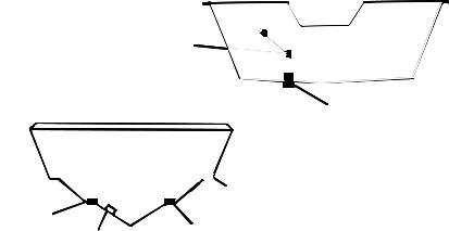
Good location
|
Poor location |
Good |
|
location |
Good location |
Poor angle |
Good and poor transducer locations.
3
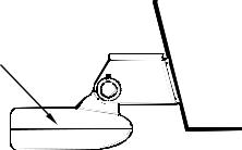
How low should you go?
For most situations, you should install your Skimmer transducer so that its centerline is level with the bottom of the boat hull.
This will usually give you the best combination of smooth water flow and protection from bangs and bumps.
Transom
Transducer centerline
Hull bottom
Align transducer centerline with hull bottom.
However, there are times when you may need to adjust the transducer slightly higher or lower. (The slots in the mounting brackets allow you to loosen the screws and slide the transducer up or down.) If you frequently lose bottom signal lock while running at high speed, the transducer may be coming out of the water as you cross waves or wakes. Move the transducer a little lower to help prevent this.
If you cruise or fish around lots of structure and cover, your transducer may be frequently kicking up from object strikes. If you wish, you may move the transducer a little higher for more protection.
There are two extremes you should avoid. Never let the edge of the mounting bracket extend below the bottom of the hull. Never let the bottom – the face – of the transducer rise above the bottom of the hull.
Transom Transducer Assembly And Mounting
The best way to install these transducers is to loosely assemble all of the parts first, place the transducer's bracket against the transom and see if you can move the transducer so that it's parallel with the ground.
4
The following instructions sometimes vary depending on the mounting bracket that came with your transducer. Single-frequency Skimmers come with a one-piece stainless steel bracket, while dual-frequency Skimmers come with a two-piece plastic mounting bracket. Use the set of instructions that fits your model.
1.Assembling the bracket.
A. One-piece bracket: Press the two small plastic ratchets into the sides of the metal bracket as shown in the following illustration. Notice there are letters molded into each ratchet. Place each ratchet into the bracket with the letter "A" aligned with the dot stamped into the metal bracket. This position sets the transducer's coarse angle adjustment for a
14° transom. Most outboard and stern-drive transoms have a 14° angle.
Dot
Align plastic ratchets in bracket.
B. Two-piece bracket: Locate the four plastic ratchets in the transducer's hardware package. Press two ratchets into the sides of the plastic bracket and two on either side of the transducer as shown in the following illustrations. Notice there are letters molded into each ratchet.
Place the ratchets into the bracket with the letter "A" aligned with the alignment mark molded into the bracket. Place the ratchets onto the transducer with the letter "A" aligned with the 12 o'clock position on the transducer stem. These positions set the transducer's coarse angle adjustment for a 14° transom. Most outboard and stern-drive transoms have a 14° angle.
5
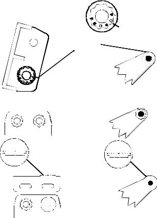
Alignment letters
Alignment |
|
positions |
|
Transducer |
|
Transducer bracket |
|
Insert and align ratchets. |
|
Transducer bracket |
Transducer |
Ratchet |
Ratchet |
|
Add ratchets to bracket and transducer.
2. Aligning the transducer on the transom.
To align the transducer to the transom, side the transducer between the ratchets. Look at the transducer from the side and adjust it so that its face is parallel to the ground. The alignment letters on either side of the bracket need be the same.
6
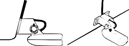
If the transducer's face isn't parallel with the ground, remove the transducer and ratchets from the bracket. Place the ratchets into the holes in the bracket with the letter "B" aligned with the dot stamped in the bracket.
Reassemble the transducer and bracket and place them against the transom. Again, check to see if you can move the transducer so it's parallel with the ground. If you can, then go to step 3A.
3.Assembling the transducer.
A. One-piece bracket: Once you determine the correct position for the ratchets, assemble the transducer as shown in the following figure. Don't tighten the lock nut at this time.
Position transducer mount on transom and mark mounting holes. Side view shown, left, and seen from above at right.
7
Nut |
washer |
|
|
Rubber |
Metal washer |
washers |
|
|
Bolt |
Assemble transducer and bracket.
B. Two-piece bracket: Once you determine the correct position for the ratchets, assemble the transducer as shown in the figure in step 2B. Don't tighten the lock nut at this time.
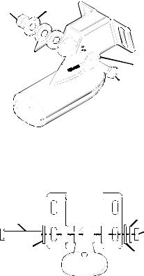
Bolt |
Lock washer |
|
Nut |
||
|
||
Flat washer |
Flat washer |
Assemble transducer and bracket.
4.Drilling mounting holes.
Hold the transducer and bracket assembly against the transom. The transducer should be roughly parallel to the ground. The transducer's centerline should be in line with the bottom of the hull. Don't let the bracket extend below the hull!
8
 Loading...