


Pub. 988-0147-582
Installation Instructions for
Skimmer Transducers
Singleor Dual-Frequency
This instruction booklet will help you install your Skimmer transducer on a transom, on a trolling motor or inside a hull. These instructions cover both singleand dual-frequency Skimmer transducers.
Read these instructions carefully before attempting the installation. Determine which of the mounting positions is right for your boat. Use extreme care if mounting the transducer inside the hull, because once it is epoxied into position, the transducer usually cannot be removed.
Remember, the transducer location and installation is the most critical part of a sonar installation!
The smaller single-frequency Skimmers typically use a one-piece, stainless steel mounting bracket. The larger dual-frequency Skimmers typically use a two-piece, plastic mounting bracket. The trolling motor mount uses a one-piece plastic bracket with an adjustable strap.
These are all "kick-up" mounting brackets. They help prevent damage if the transducer strikes an object while the boat is moving. If the transducer does "kick-up," the bracket can easily be pushed back into place without tools.
Depending on your sonar unit's connectors, your transducer cable may also have the sonar unit's power cable attached to it. If that is the case, be sure to install the transducer first, before connecting the power cable to a power source. See the instructions in your sonar unit's manual for connecting the power cable to a battery or other power supply. (Lost your manual? Most current product manuals are available for free download from the manufacturers' web sites. See the back page for web links.)
Recommended Tools and supplies
If you prefer the option of routing the cable through the transom, you will need either a 1" drill bit or a 5/8" drill bit depending on the type of cable connector (see figure at top of page 11). Each transom mount requires use of a high quality, marine grade aboveor below-waterline sealant/adhesive compound. The following installation types also call for these recommended tools and required supplies (supplies are not included):
Single-frequency transom installations
Tools include: two adjustable wrenches, drill, #29 (0.136") drill bit, flathead screwdriver. Supplies: none.
1
Dual-frequency transom installations
Tools: two adjustable wrenches, drill, #20 (0.161") drill bit, flat-head screwdriver. Supplies: four, 1" long, #12 stainless steel slotted wood screws.
Single-frequency trolling motor installations
Tools: two adjustable wrenches, flat-head screwdriver. Supplies: plastic cable ties.
Shoot-through hull installations
Tools: these will vary depending on your hull's composition. Consult your boat dealer or manufacturer. Other tools are a wooden craft stick or similar tool for stirring and applying epoxy, and a paper plate or piece of cardboard to mix the epoxy on. Supplies: rubbing alcohol, 100 grit sandpaper, specially formulated epoxy adhesive available from LEI (see ordering information on page 20). A sandwich hull also requires polyester resin.
Selecting a Transducer Location
1.The location must be in the water at all times, at all operating speeds.
2.The transducer must be placed in a location that has a smooth flow of water at all times. If the transducer is not placed in a smooth flow of water, interference caused by bubbles and turbulence will show on the sonar's display in the form of random lines or dots whenever the boat is moving.
NOTE:
Some aluminum boats with strakes or ribs on the outside of the hull create large amounts of turbulence at high speed. These boats typically have large outboard motors capable of propelling the boat at speeds faster than 35 mph. Typically, a good transom location on aluminum boats is between the ribs closest to the engine.
3.The transducer should be installed with its face pointing straight down, if possible. For shoot-thru applications: Many popular fishing
boat hulls have a flat keel pad that offers a good mounting surface. On vee hulls, try to place the transducer where the deadrise is 10° or less.
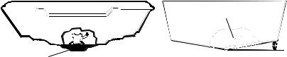
Deadrise less than 10°
 Strakes
Pad
Left, vee pad hull; right, vee hull. A pod style transducer is shown here, but the principle is the same for Skimmers inside a hull.
4. If the transducer is mounted on the transom, make sure it doesn't
2
interfere with the trailer or hauling of the boat. Also, don't mount it closer than approximately one foot from the engine's lower unit. This will prevent cavitation (bubble) interference with propeller operation.
5.If possible, route the transducer cable away from other wiring on the boat. Electrical noise from engine wiring, bilge pumps and aerators can be displayed on the sonar's screen. Use caution when routing the transducer cable around these wires.
CAUTION: Clamp the transducer cable to transom near the transducer. This will help prevent the transducer from entering the boat if it is knocked off at high speed.
Good location
|
Poor location |
|
Good |
|
|
location |
Good location |
|
Poor angle |
||
|
Good and poor transducer locations.
How low should you go?
For most situations, you should install your Skimmer transducer so that its centerline is level with the bottom of the boat hull. This will usually give you the best combination of smooth water flow and protection from bangs and bumps.
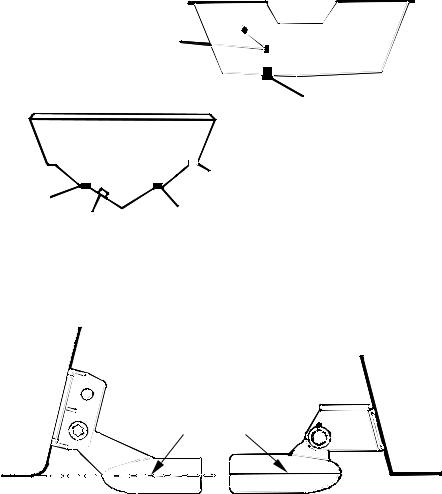
Transom
Transom
Transducer centerline
Hull bottom |
Hull bottom |
Align transducer centerline with hull bottom. A dual frequency transducer is shown at left and a single frequency transducer at right.
However, there are times when you may need to adjust the transducer
3
slightly higher or lower. (The slots in the mounting brackets allow you to loosen the screws and slide the transducer up or down.) If you frequently lose bottom signal lock while running at high speed, the transducer may be coming out of the water as you cross waves or wakes. Move the transducer a little lower to help prevent this.
If you cruise or fish around lots of structure and cover, your transducer may be frequently kicking up from object strikes. If you wish, you may move the transducer a little higher for more protection.
There are two extremes you should avoid. Never let the edge of the mounting bracket extend below the bottom of the hull. Never let the bottom – the face – of the transducer rise above the bottom of the hull.
Shoot-thru-hull vs. Transom Mounting
In a shoot-thru-hull installation, the transducer is bonded to the inside of the hull with epoxy. The sonar "ping" signal actually passes through the hull and into the water. This differs from a bolt-thru-hull installation (often called simply "thru-hull"). In that case, a hole is cut in the hull and a specially designed transducer is mounted through the hull with a threaded shaft and nut. This puts the transducer in direct contact with the water.
Typically, shoot-thru-hull installations give excellent high speed operation and good to excellent depth capability. There is no possibility of transducer damage from floating objects, as there is with a transommounted transducer. A transducer mounted inside the hull can't be knocked off when docking or loading on a trailer.
However, the shoot-thru-hull installation does have its drawbacks. First, some loss of sensitivity does occur, even on the best hulls. This varies from hull to hull, even from different installations on the same hull. This is caused by differences in hull lay-up and construction.
Second, the transducer angle cannot be adjusted for the best fish arches on your sonar display. (This is not an issue for flasher-style sonars.) Lack of angle adjustment can be particularly troublesome on hulls that sit with the bow high when at rest or at slow trolling speeds.
Third, a transducer CAN NOT shoot through wood and metal hulls. Those hulls require either a transom mount or a thru-hull installation.
Fourth, if your Skimmer transducer has a built in temp sensor, it will only show the temperature of the bilge, not the water surface temp.
Follow the testing procedures listed in the shoot-thru-hull installation section at the end of this instruction booklet to determine if you can satisfactorily shoot through the hull.
4
TRANSOM TRANSDUCER ASSEMBLY AND MOUNTING
The best way to install these transducers is to loosely assemble all of the parts first, place the transducer's bracket against the transom and see if you can move the transducer so that it's parallel with the ground.
The following instructions sometimes vary depending on the mounting bracket that came with your transducer. Single frequency Skimmers come with a one-piece stainless steel bracket, while dual frequency Skimmers come with a two-piece plastic mounting bracket. Use the set of instructions that fits your model.
1.Assembling the bracket.
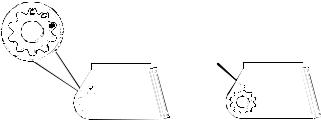
A. One-piece bracket: Press the two small plastic ratchets into the sides of the metal bracket as shown in the following illustration. Notice there are letters molded into each ratchet. Place each ratchet into the bracket with the letter "A" aligned with the dot stamped into the metal
bracket. This position sets the transducer's coarse angle adjustment for a 14° transom. Most outboard and stern-drive transoms have a 14° angle.
Dot
Align plastic ratchets in bracket.
B. Two-piece bracket: Locate the four plastic ratchets in the transducer's hardware package. Press two ratchets into the sides of the plastic bracket and two on either side of the transducer as shown in the following illustrations. Notice there are letters molded into each ratchet. Place the ratchets into the bracket with the letter "A" aligned with the alignment mark molded into the bracket. Place the ratchets onto the transducer with the letter "A" aligned with the 12 o'clock position on the transducer stem. These positions set the transducer's coarse angle adjustment for a 14° transom. Most outboard and sterndrive transoms have a 14° angle.
5

Alignment letters
Alignment
positions
Transducer |
|
|
Transducer bracket |
|
|
Insert and align ratchets. |
|
|
Transducer |
Transducer |
|
bracket |
||
|
Ratchet |
Ratchet |
|
Add ratchets to bracket and transducer.
2.Aligning the transducer on the transom.
A. One-piece bracket: Slide the transducer between the two ratchets. Temporarily slide the bolt though the transducer assembly and hold it against the transom. Looking at the transducer from the side, check to see if it will adjust so that its face is parallel to the ground. If it does, then the "A" position is correct for your hull.
If the transducer's face isn't parallel with the ground, remove the transducer and ratchets from the bracket. Place the ratchets into the holes in the bracket with the letter "B" aligned with the dot stamped in the bracket.
Reassemble the transducer and bracket and place them against the transom. Again, check to see if you can move the transducer so it's
6
 Loading...