


HOOK Series
Operation manual
ENGLISH
HOOK-4 |
HOOK-5 |
HOOK-7 |
HOOK-9 |
|
|
|
|
lowrance.com
Copyright © 2016 Navico
All rights reserved.
Lowrance® and Navico® are registered trademarks of Navico.
Fishing Hot Spots® is a registered trademark of Fishing Hot Spots Inc.
Navionics® is a registered trademark of Navionics, Inc.
Navico may find it necessary to change or end our policies, regulations and special offers at any time. We reserve the right to do so without notice. All features and specifications subject to change without notice.
Compliance Statements
Lowrance HOOK-4, HOOK-5, HOOK-7 and HOOK-9
•meets the technical standards in accordance with Part 15.103 of the FCC rules
•complies with CE under RTTE directive 1999/5/EC
•complies with the requirements of level 2 devices of the Radiocommunications (Electromagnetic Compatibility) standard 2008
For more information please refer to our website: www.lowrance.com.

Warning
The user is cautioned that any changes or modifications not expressly approved by the party responsible for compliance could void the user’s authority to operate the equipment. This equipment has been tested and found to comply with the limits for a Class B digital device, pursuant to Part 15 of the FCC rules. These limits are designed to provide reasonable protection against harmful interference in a residential installation. This equipment generates, uses and can radiate radio frequency energy and, if not installed and used in accordance with the instructions, may cause harmful interference to radio communications. However, there is no guarantee that the interference will not occur in a particular installation. If this equipment does cause harmful interference to radio or television reception, which can be determined by turning the
equipment off and on, the user is encouraged to try to correct the interference by one or more of the following measures:
•Reorient or relocate the receiving antenna
•Increase the separation between the equipment and receiver
•Connect the equipment into an outlet on a circuit different from that of the receiver
•Consult the dealer or an experienced technician for help
WARNING: When a GPS unit is used in a vehicle, the vehicle operator is solely responsible for operating the vehicle in a safe manner. Vehicle operators must maintain full surveillance of all pertinent driving or boating conditions at all times. An accident or collision resulting in damage to property, personal injury or death could occur if the operator of a GPS-equipped vehicle fails to pay full attention to travel conditions
and vehicle operation while the vehicle is in motion.
NOTE: This manual covers HOOK-4, HOOK-5, HOOK-7 and HOOK-9 units. As a result, screenshots of menus and dialogs may not match the look of your unit.

Table of contents |
|
Introduction...................................... |
6 |
Unit controls............................................. |
6 |
Inserting microSD cards........................... |
7 |
Basic operation................................ |
8 |
Setup wizard............................................ |
8 |
Pages....................................................... |
8 |
Selecting pages........................................ |
8 |
Page menus............................................. |
8 |
Working with menus............................... |
10 |
Dialogs................................................... |
10 |
Entering text........................................... |
11 |
Fishing modes........................................ |
11 |
Cursor.................................................... |
12 |
Goto cursor............................................ |
12 |
Advanced mode .................................... |
13 |
Standby mode........................................ |
13 |
Restore defaults..................................... |
13 |
Pages............................................... |
14 |
Steer page.............................................. |
14 |
Sonar page............................................. |
14 |
Downscan page .................................... |
15 |
Chart page............................................. |
15 |
Combo pages......................................... |
16 |
Overlay data........................................... |
17 |
Sonar operation.............................. |
18 |
CHIRP.................................................... |
18 |
Trackback............................................... |
19 |
Sonar menu............................................ |
19 |
Sonar options......................................... |
23 |
Downscan options.................................. |
24 |
Sonar settings........................................ |
25 |
Installation.............................................. |
27 |
Table of Contents | HOOK series |
4 |
DownScan operation..................... |
28 |
Trackback .............................................. |
28 |
DownScan menu.................................... |
28 |
Ping speed............................................. |
30 |
Downscan options.................................. |
30 |
Chart operation.............................. |
33 |
Chart menu............................................ |
33 |
Waypoints, Routes, Trails...................... |
34 |
Routes screen........................................ |
35 |
Trails screen........................................... |
39 |
Orientation.............................................. |
41 |
Chart settings......................................... |
42 |
Navigation settings................................. |
43 |
AIS................................................... |
45 |
AIS setup................................................ |
45 |
Target symbols....................................... |
46 |
Viewing AIS target information............... |
47 |
Settings........................................... |
48 |
Settings menu........................................ |
48 |
System................................................... |
48 |
Alarms ................................................... |
50 |
Saving screenshots................................ |
50 |
Specifications................................. |
52 |
Index................................................ |
56 |
5 |
Table of Contents | HOOK series |
Introduction
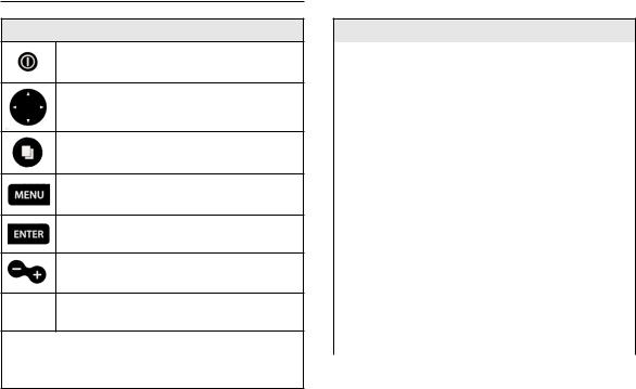
Unit controls
LIGHT/POWER: controls backlight level and turns unit on/off
KEYPAD: controls cursor & selects items on menus
PAGES: allows you to select a page to view
MENU: opens settings, context and page menus
ENTER: finalizes menu selections; save waypoint at cursor position
MOB: press and hold both Zoom keys to create a Man Overboard waypoint
 ZOOM Keys: used to zoom in/zoom out
microSD slot: insert a blank microSD card to save screen captures; or insert a microSD mapping card to use mapping data
Getting started
Turn unit |
To turn on/off the unit, press and |
|
hold the LIGHT/POWER key for |
||
on/off |
||
three seconds. |
||
|
||
|
|
|
|
Press the ZOOM IN and ZOOM OUT |
|
Man |
keys at the same time to set a Man |
|
Overboard waypoint. Your system will |
||
Overboard |
automatically create an active route |
|
waypoint |
back to the MOB waypoint. You must |
|
|
cancel navigation to terminate the |
|
|
function. |
|
|
|
|
Adjusting |
This unit has 10 backlight levels. |
|
the |
Press the LIGHT/POWER key to |
|
backlight |
switch backlight levels. |
|
|
|
|
Muting |
Select Audio from the System |
|
menu and press ENTER. Enable/ |
||
Audio |
||
disable Mute. |
||
|
Introduction | HOOK series |
6 |
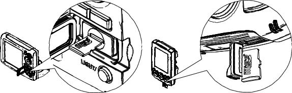
Inserting microSD cards
Carefully slide the microSD card into the slot until it clicks into place. To remove, carefully push in the card until it clicks out of place.
HOOK-5, HOOK-7 and HOOK-9 |
HOOK-4 |
7 |
Introduction | HOOK series |
Basic operation
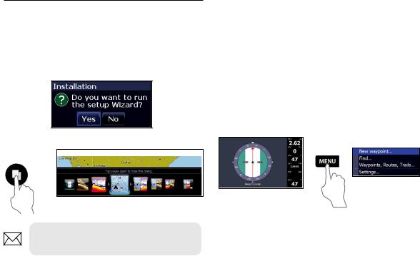
Setup wizard
The Setup wizard will appear when the unit is turned on for the first time. To choose your own settings, do not run the setup wizard. To restart the Setup wizard, restore defaults.
Pages
Pages dialog
NOTE: Available pages vary depending on the unit and the connected transducer.
Selecting pages
To select a page, press the keypad in the direction of the desired page and press ENTER.
Page menus
The Steer, Downscan, Sonar and Chart pages have menus that can only be accessed when those pages are displayed.
Steer menu
Steer page
Basic Operation | HOOK series |
8 |

Downscan page
Sonar page
Chart page
Downscan menu
Sonar menu
Chart menu
Combo pages
|
|
|
Two-panel page |
|
Three-panel page |
Press the PAGES key twice to switch active panels. The page menu for active page will be displayed when the MENU key is pressed. The active panel is denoted by an orange border.
Accessing the Settings menu
x2
9 |
Basic Operation | HOOK series |
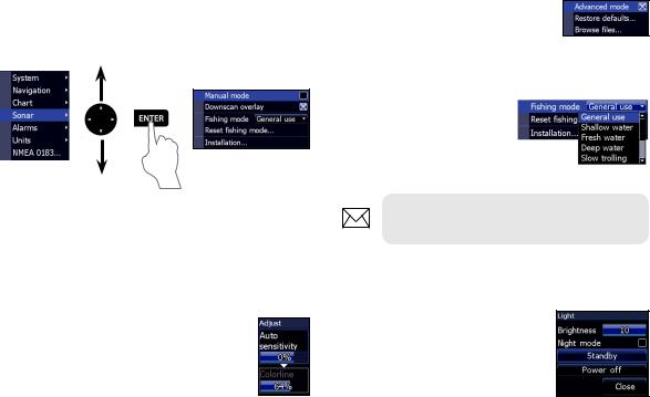
Accessing menu items
The keypad and ENTER key are used to select menu items and open submenus. Use the keypad to highlight the desired item and press ENTER.
Working with menus
There are several menu types used to make adjustments to options and settings, including scrollbars, on/off features and dropdown menus.
Scrollbars
Select the scrollbar and press the keypad left (decrease) or right (increase).
On/Off features
Select an on/off menu item and press ENTER to turn it on/off.
Dropdown menus
Access the dropdown menu and press the keypad up/down to select the desired item and press
ENTER.
NOTE: Press the MENU key to Exit menus.
Dialogs
Dialogs are used for user input or for presenting information to the user. Depending on the type of entry, different methods are used to confirm, cancel or close the dialog.
Basic Operation | HOOK series |
10 |
Entering text
Some functions, like naming a waypoint, route or trail, will require you to input text.
To input text:
1.Use the keypad to select the desired character and press ENTER.
2.Repeat Step 1 for each character.
3.When entry is completed, highlight OK and press ENTER.
Switches letters to uppercase/ lowercase
Switches keyboard between Alpha and QWERTY layout
Fishing modes
(Conventional sonar only)
Fishing modes enhance the performance of your unit by providing preset packages of sonar settings geared to specific fishing conditions.
11 |
Basic Operation | HOOK series |

Fishing mode options
General Use |
1000 ft or less |
Coastal |
|
|
|
|
|
Shallow |
60 ft or less |
Shallow weedy |
|
Water |
bottoms |
||
|
|||
Fresh Water |
400 ft or less |
Inland/Near coastal |
|
|
|
|
|
Deep Water |
1000 ft or more |
Offshore |
|
|
|
|
|
Slow |
400 ft or less |
Inland/Coastal |
|
Trolling |
|||
|
|
||
Fast |
400 ft or less |
Inland/Coastal |
|
Trolling |
|||
|
|
||
Clear Water |
400 ft or less |
Inland/Coastal |
|
|
|
|
|
Brackish |
400 ft or less |
Fresh-Saltwater mix |
|
Water |
|||
|
|
||
|
|
|
|
Ice |
400 ft or less |
Ice fishing |
|
|
|
|
NOTE: Use Fresh Water mode when fishing in less than 100 feet of water; otherwise your unit may not track bottom properly.
Cursor
The keypad moves the cursor around the display, allowing you to scroll the map, select map items and review sonar history.
Press MENU and select Return to vessel or Exit cursor mode to clear the cursor.
Goto cursor
Used to navigate to the cursor.
1.Move the cursor to a desired location and press MENU.
2.Select Goto cursor and press ENTER.
Basic Operation | HOOK series |
12 |
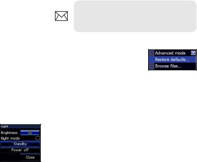
Advanced mode
Enables advanced features and settings.
The following features are enabled when Advanced mode is turned on:
•Navigation (Enables arrival radius, offcourse distance and Bearings setting)
•Alarms (Enables arrival, off course and anchor alarm options)
•NMEA 0183 Output (Requires optional Power/NMEA cable 000-0127-49)
•Units (Enables distance, speed, depth, temperature, and bearings options)
Standby mode
Lowers power consumption by turning off sonar and the display.
Press the PWR/LIGHT key to access the Backlight dialog.
NOTE: Leaving your unit in Standby mode when your boat is not in use will run down your battery.
Restore defaults
Resets unit options and settings to defaults.
13 |
Basic Operation | HOOK series |
Pages
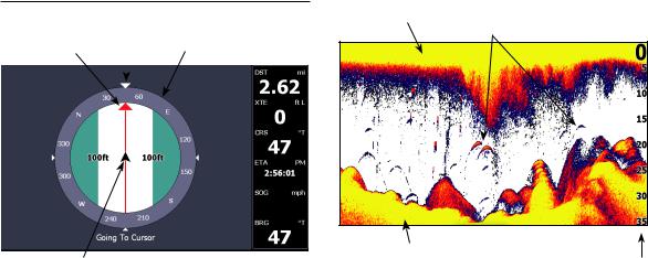
Direction to cursor
Current Track |
Compass |
|
|
Your location |
Navigation |
|
information |
Steer page
The Steer page has a compass that shows your current track, the direction to your destination, and a digital data navigation panel.
Surface Clutter
Fish arches
Bottom
Range
Scale
Sonar page
Displays the water column moving from right to left on your unit’s screen.
Pages | HOOK series |
14 |
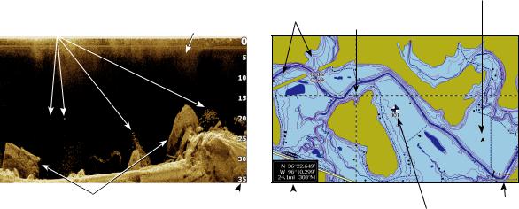
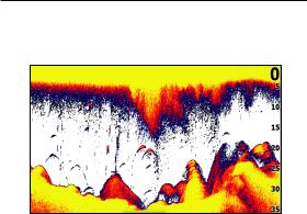
Fish |
Surface clutter |
|
|
|
|
Structure  Range scale
Downscan page
The Downscan page shows the water column moving from right to left. You can overlay downscan sonar on the conventional sonar page by selecting Downscan Overlay on the Sonar settings menu.
Current location
Depth
contours Cursor
|
|
|
|
|
|
|
Zoom |
|
|
|
|
Current cursor location; |
Waypoint |
||
distance to cursor |
Range |
||
Chart page
Consists of map that moves in real-time as you move. By default, the map is shown from a birdseye view with North at the top of the screen.
15 |
Pages | HOOK series |
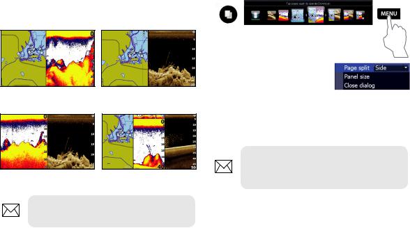
Combo pages
This unit has four pre-configured combo pages.
Chart/Sonar Chart/Downscan
Sonar/Downscan Chart/Sonar/Downscan
NOTE: Press the PAGES key twice to switch active panels.
Customizing combo pages
You can adjust the panel size of combo pages and control how the pages will be arranged on the screen:
vertically (side) or horizontally (over).
To make adjustments to combo page panels, select a combo page from the Pages carousel and press MENU.
NOTE: To adjust panel size, access the customize menu after selecting a combo page for display and select Panel size.
Pages | HOOK series |
16 |
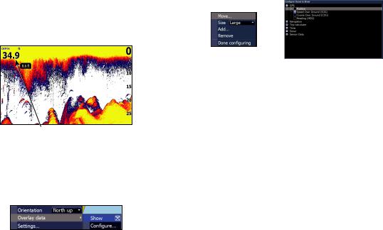
Overlay data
Used to select data shown on the Sonar, Structure and Chart pages.
Overlay data
Show
Enables/disables the display of overlay data, allowing you to remove overlay data from the screen without deleting the current overlay data configuration.
Configure
Allows you to select/customize overlay data.
To add overlay data:
1.From the Sonar, Chart or DownScan page, press MENU.
2.Select Overlay data and press ENTER.
3.Select Configure and press ENTER.
4.Press MENU and select Add. Press
ENTER.
5.Select a data category and press
ENTER.
6.Select the desired data and press
ENTER.
7.Press MENU and select Return to
Overlays. Press ENTER.
8.Press MENU, select Done Configuring and press ENTER.
17 |
Pages | HOOK series |
Sonar operation
This unit supports two types of sonar:
Conventional and Downscan.
The features described in this section are for conventional sonar. Refer to the Downscan section for information on Downscan features.
CHIRP
A CHIRP (Compressed High Intensity Radar Pulse) transducer transmits a modulated pulse of multiple frequencies within the bandwidth
of the selected transducer type. This results in better image quality, better target separation and greater depth penetration.
This unit supports High CHIRP, Medium CHIRP and Low CHIRP, depending on the transducer.
CHIRP can be used with Lowrance conventional sonar transducers.
•50/200 kHz (Low/High CHIRP)
•83/200 kHz (Medium/High CHIRP)
To use CHIRP, select the desired CHIRP frequency from the Frequency menu.
Sonar Operation | HOOK series |
18 |
 Loading...