


 Loading...
Link-5VHF
User Guide
ENGLISH
lowrance.com

Copyright © 2012 Navico
All rights reserved.
Lowrance® is a registered trademark of Navico
No part of this manual may be copied, reproduced, republished, transmitted or distributed for any purpose, without prior written consent of Lowrance Electronics.
Any unauthorized commercial distribution of this manual is strictly prohibited.
Lowrance Electronics may find it necessary to change or end our policies, regulations, and special offers at any time. We reserve the right to do so without notice. All features and specifications subject to change without notice.
All screens in this manual are simulated.
For free owner’s manuals and the most current information on this product, its operation and accessories, visit our web site: www.lowrance.com
Important safety information
Please read carefully before installation and use.
|
|
|
This is the safety alert symbol. It is used to alert you to potential |
|
DANGER |
|
|
|
|
personal injury hazards, Obey all safety messages that follow this |
|
|
|
|
symbol to avoid possible injury or death. |
|
|
|
|
|
|
|
WARNING indicates a potentially hazardous situation which, if not |
|
WARNING |
|
|
|
|
avoided, could result in death or serious injury |
|
|
|
|
|
|
|
|
|
|
|
|
CAUTION indicates a potentially hazardous situation which, if not |
|
CAUTION |
|
|
|
|
avoided, could result in minor or moderate injury. |
|
|
|
|
|
|
|
|
|
|
|
|
CAUTION used without the safety alert symbol indicates a po- |
|
CAUTION |
|
|
|
|
tentially hazardous situation which, if not avoided, may result in |
|
|
|
|
property damage. |
|
|
|
|
Section 1 - General Information........................................................................ |
6 |
1-1 Features.................................................................................................................................................. |
6 |
1-2 Customizing your Lowrance VHF Radio..................................................................................... |
7 |
1-3 How to Display and Navigate Menus.......................................................................................... |
7 |
1-4 How to Enter Alphanumeric Data................................................................................................. |
7 |
1-5 LCD Symbols and Meanings........................................................................................................... |
7 |
1-6 Basic Operation and Key Functions............................................................................................. |
9 |
Section 2 - The Radio Menu (MENU)................................................................. |
13 |
2-1 Radio Menu Options (Menu) ...................................................................................................... |
13 |
2-2 Maintain Your Buddy List (BUDDY LIST).................................................................................. |
14 |
2-2-1 Add an Entry..................................................................................................................................................... |
14 |
2-2-2 Edit an Entry...................................................................................................................................................... |
14 |
2-2-3 Delete an Entry............................................................................................................................................... |
15 |
2-3 Local or Distance Sensitivity (LOCAL/DIST)............................................................................ |
15 |
2-3-1 Set DISTANT Sensitivity.............................................................................................................................. |
15 |
2-3-2 Set LOCAL Sensitivity.................................................................................................................................. |
15 |
2-4 Backlighting (BACKLIGHT) and Contrast (CONTRAST)...................................................... |
15 |
2-4-1 Set the Backlighting Level........................................................................................................................ |
16 |
2.4.2 Set the Contrast Level.................................................................................................................................. |
16 |
2-5 GPS Data and Time (GPS/DATA).................................................................................................. |
16 |
2-5-1 Manually Enter Position and UTC Time (MANUAL)................................................................... |
16 |
2-5-2 Local Time (TIME OFFSET)........................................................................................................................ |
17 |
2-5-3 Time Format Options (TIME FORMAT).............................................................................................. |
17 |
2-5-4 Time Display Options (TIME DISPLAY).............................................................................................. |
18 |
2-5-5 Position Display Options (LL display)................................................................................................ |
18 |
2-5-6 Course & Speed Display Options (COG/SOG).............................................................................. |
18 |
2-5-7 GPS Alert Options (ALERT) ..................................................................................................................... |
19 |
2-6 GPS Simulator (SIMULATOR)........................................................................................................ |
19 |
2-7 Reset to Factory Defaults (RESET).............................................................................................. |
19 |
Section 3 - Radio Setup Menu (RADIO SETUP)................................................. |
20 |
3-1 Radio Setup Menu (RADIO SETUP)............................................................................................ |
20 |
3-2 Channel (UIC).................................................................................................................................... |
20 |
3-3 Channel Names (CH NAME)......................................................................................................... |
21 |
3-4 RING & BEEP Volume (RING VOLUME) and (KEY BEEP)...................................................... |
21 |
3-5 Internal Speaker Connections (INT SPEAKER)....................................................................... |
21 |
3-6 Set the Priority Channel (WATCH MODE)................................................................................ |
22 |
3-7 Weather Alert (Wx ALERT) ........................................................................................................... |
22 |
3-8 NMEA protocol (COM PORT)....................................................................................................... |
22 |
Lowrance - Link-5 Operation and Installation Instructions |
3 |
Section 4 - DSC Setup Menu (DSC SETUP)........................................................ |
23 |
4-1 DSC Setup - Menu Options.......................................................................................................... |
23 |
4-2 Enter or View Your USER MMSI (USER MMSI)......................................................................... |
23 |
4-2-1 Enter your MMSI............................................................................................................................................. |
23 |
4-2-2 View your MMSI ............................................................................................................................................. |
24 |
4-3 Maintain Your Groups (GROUP SETUP).................................................................................... |
24 |
4-3-1 Create a Group (GROUP SETUP)........................................................................................................... |
24 |
4-3-2 Edit Group Name Details ......................................................................................................................... |
25 |
4-3-3 Delete a Group................................................................................................................................................ |
25 |
4-4 Response to Individual Calls (INDIV REPLY)........................................................................... |
25 |
4-5 ATIS MMSI & ATIS Functionality.................................................................................................. |
26 |
4-5-1 Enter or Edit YOUR ATIS MMSI................................................................................................................ |
26 |
4-5-2 View your ATIS MMSI................................................................................................................................... |
26 |
4-5-3 Enable ATIS Functionality (ATIS FUNC)............................................................................................. |
27 |
4-6 DSC functionality options (DSC FUNC).................................................................................... |
27 |
4-7 Response Type to LL Polling Calls (LL REPLY)........................................................................ |
27 |
4-8 Automatic Channel switching (AUTO SWITCH).................................................................... |
28 |
4-9 DSC Test Reply (TEST REPLY)....................................................................................................... |
29 |
4-10 Set the inactivity timer (TIMEOUT)......................................................................................... |
29 |
Section 5 - Sending and Receiving DSC Calls................................................... |
30 |
5-1 What is DSC?...................................................................................................................................... |
30 |
5-2 Sending DSC calls............................................................................................................................ |
30 |
5-2-1 Make a Routine Call (INDIVIDUAL)...................................................................................................... |
31 |
5-2-2 Retrying a Routine Call............................................................................................................................... |
32 |
5-2-3 Acknowledgement of an Individual Incoming Call (INDIV)................................................ |
32 |
5-2-4 Recall the Most Recent Incoming Call (LAST CALL)................................................................. |
33 |
5-2-5 Call a Group (GROUP).................................................................................................................................. |
33 |
5-2-6 Call All Ships (ALL SHIPS)........................................................................................................................... |
33 |
5-2-7 Call using the Call Log (CALL LOG)..................................................................................................... |
34 |
5-2-8 Call using the Distress Log (DISTR LOG).......................................................................................... |
34 |
5-2-9 Call using the Sent Call Log (SENT CALL)....................................................................................... |
35 |
5-2-10 Request the LL Position of a Buddy (LL REQUEST)................................................................. |
35 |
5-2-11 Make a DSC test call (DSC TEST)........................................................................................................ |
36 |
5-3 Receiving DSC Calls......................................................................................................................... |
37 |
5-3-1 Receiving an All Ships Call (ALL SHIPS)............................................................................................ |
38 |
5-3-2 Receiving an Individual Call (INDIV)................................................................................................... |
38 |
5-3-3 Receiving a Group Call (GROUP).......................................................................................................... |
39 |
5-3-4 Receiving a Geographic Call (GEOGRAPH).................................................................................... |
40 |
5-3-5 Receiving a Polled Position Call (POSITION).................................................................................. |
40 |
4 |
Lowrance - Link-5 Operation and Installation Instructions |
Section 6 - Distress Calls................................................................................... |
41 |
6-1 Sending a Distress Call................................................................................................................... |
41 |
6-2 Receiving a Distress Call (DISTRESS!)........................................................................................ |
43 |
6-3 Distress Acknowledgement (DISTRESS ACK) ........................................................................ |
43 |
6-4 Distress Relay Individual (INDIV DISTR RELAY)...................................................................... |
44 |
Section 7 - Installation..................................................................................... |
45 |
Installation Options................................................................................................................................ |
45 |
Location Requirements......................................................................................................................... |
45 |
Checklist..................................................................................................................................................... |
46 |
Gimbal Installation................................................................................................................................. |
47 |
Change the Viewing Angle.................................................................................................................. |
47 |
Recessed Installation............................................................................................................................. |
47 |
Install the Microphone Bulkhead Mount....................................................................................... |
48 |
Fix the DSC label...................................................................................................................................... |
49 |
Connect the Radio Cables.................................................................................................................... |
49 |
Set Up the Radio...................................................................................................................................... |
50 |
Enter Your User MMSI............................................................................................................................ |
50 |
The Completed Installation................................................................................................................. |
51 |
Appendix A - Technical Specifications............................................................. |
52 |
Appendix B - Troubleshooting......................................................................... |
54 |
Appendix C - US & ROW VHF Marine Channel Charts...................................... |
55 |
C-1 International Channel Chart........................................................................................................ |
55 |
Special Notes on International Channel Usage....................................................................................... |
56 |
C-2 USA Channel Chart......................................................................................................................... |
57 |
Special Notes on USA Channel Usage........................................................................................................... |
58 |
C-3 CANADA Channel Chart................................................................................................................ |
59 |
Special Notes on Canada Channel Usage................................................................................................... |
60 |
C-4 US & Canada WEATHER Channels.............................................................................................. |
61 |
Appendix D - EU VHF Marine Channel Charts................................................. |
62 |
D-1 EU International Channel Chart................................................................................................. |
62 |
Special Notes on EU International Channel Usage................................................................................ |
63 |
D-2 Inland Waterways Country Specific table - ATIS ON........................................................... |
64 |
D-3 Special Channels 2 ......................................................................................................................... |
67 |
Appendix E - MMSI, FCC and License Information.......................................... |
68 |
FCC Compliance.......................................................................................................................................................... |
68 |
Lowrance - Link-5 Operation and Installation Instructions |
5 |

Section 1 - General Information
1-1 Features
Congratulations on your purchase of this Lowrance Link-5 marine band VHF radio. Your Link-5 provides the following useful features:
•Prominent channel display
•Adjustable contrast settings for the LCD
•Adjustable keypad backlighting for easy night-time use
•Waterproof and submersible to comply with JIS-7
•GPS latitude and longitude (LL) and time display (when connected to a GPS)
•Choice of High or Low (25 W or 1 W) transmission power
•6 key handset mic with built-in speaker
•Powerful 4 W external audio output
•Access to all currently-available marine VHF channel banks (USA, Canada, International) including weather channels where available (model dependant)
•Special CH16/9 key for quick access to the priority (international distress) channel
•Special 3CH key to select your three favourite channels
•Dedicated Wx (Weather) key
•PSCAN (similar to dual watch) facility
•DSC (Digital Select Calling) capability that meets Global DSC Class D Standards
•Separate CH70 receiver included built in
•DISTRESS call button to automatically transmit the MMSI and position until an acknowledgement is received
•Easy access to a buddy list of up to 20 favourite people
•MMSI storage for three favourite groups
•Group Call and All Ships Call facility
•LL position polling information
•Weather alert facility where available (US models)
•ATIS facility for inland waterways (EU models)
•With DSC Auto-Switch disable and DSC Test function
6 |
Lowrance - Link-5 Operation and Installation Instructions |

1-2 Customizing your Lowrance VHF Radio
You can customize the radio to suit your individual preferences. Some preferences can be set directly through the keys as explained in this Section. Other preferences are set up through the built-in menus and these are explained in the other Sections.
You can check the software version of the radio and the User MMSI each time the radio is turned on, the screen will display the software version and the USER MMSI if one is programmed into the radio.
1-3 How to Display and Navigate Menus
1.Press MENU (or CALL). Note that only four menu items can be displayed at any one time on the screen.
2.Some line items may show an ▲ or ▼ indicator. This means there is more information available to show. Scroll (rotate the Rotary knob, or use + / - keys on the hand mic) to scroll up and down the menu until the cursor is positioned at the desired option. Press ENT (press the Push To Select) to display that option.
3.Make any entries or changes as explained in the following section.
4.Press ENT to confirm changes. Otherwise, press EXIT to keep the original entry.
5.Press EXIT to backup one screen (this key is equivalent to an ESC function on a PC).
1-4 How to Enter Alphanumeric Data
If your radio does not have the optional alphanumeric microphone, you can Rotate the Rotary knob, or use + / - keys on the microphone key to enter alphanumeric data.
•Press - to count through numbers, or hold down to scroll rapidly to the desired number.
•Press + to step through the alphabet, or hold down to scroll rapidly to the desired character.
•If you make an error, press - until < is displayed, then press ENT to backup and correct the entry.
1-5 LCD Symbols and Meanings
Link-5 LCD showing all segments: |
Typical Link-5 startup screen: |
LINK5 AUS/NZ
VER:V1.999
DSC IS ON
ID:111222333
Lowrance - Link-5 Operation and Installation Instructions |
7 |
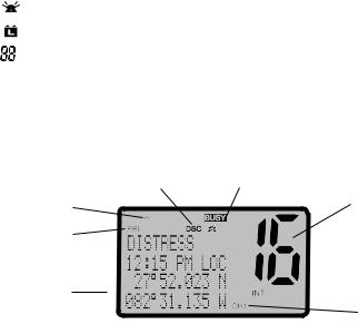
This simulation shows the locations of all the following information symbols:
Symbol |
Meaning |
|
|
|
|
||||||||
|
|
|
|
|
Transmitting. |
|
|
|
|
||||
|
TX |
|
|
|
|
||||||||
HI LO |
Transmission power. High (HI) 25W or Low (LO) 1W. |
||||||||||||
WX |
Weather channel. |
|
|
|
|||||||||
WX ALT |
Weather Alert. Alarm beeps will sound (US models only). |
||||||||||||
|
|
|
|
|
|
||||||||
|
BUSY |
|
|
Receiver busy with an incoming signal. |
|||||||||
PRI |
Priority channel is selected. |
|
|
|
|||||||||
|
|
|
|||||||||||
|
D |
|
Duplex operation. Otherwise, blank for Simplex operation. |
||||||||||
|
|
|
|
|
|
|
|
|
|
|
|
|
|
|
LOCAL |
Local calling is selected. Otherwise, blank for distance calling. |
|||||||||||
DSC |
DSC capability is available. |
|
|
|
|||||||||
|
|
|
|
|
|
|
Incoming DSC call. |
|
|
|
|||
|
|
|
|
|
|
|
Low Battery warning (activates at 10.5 V). |
||||||
|
|
|
|
|
|
|
|||||||
|
|
|
|
|
|
|
Channel selected. |
|
|
|
|||
USA INT CAN |
Selected channel bank for VHF radio operations and regulations. |
||||||||||||
|
|
|
|
|
|
DSC Auto channel switch function is disabled (OFF) (see section 4-8) |
|||||||
|
X |
|
|
|
|
||||||||
B A |
Channel suffix, if applicable. |
|
|
|
|||||||||
CH1 CH2 CH3 |
Shows which of the 3 favourite channels, if any, are selected. |
||||||||||||
|
|
|
|
|
|
|
Otherwise blank. |
|
|
|
|||
ATIS |
EU models only - must be enabled when in European inland waterways. |
||||||||||||
A typical display: |
|
|
|||||||||||
|
|
|
|
|
|
|
|
|
|
|
|
||
|
|
|
|
|
|
|
|
|
|
|
|
||
|
|
|
|
|
|
|
|
|
|
|
|
|
|
|
|
|
|
|
|
|
|
|
|
|
|
|
|
|
|
|
|
|
|
|
|
|
|
||||
|
|
|
|
|
|
|
|
|
|
|
|
||
|
|
|
|
|
|
|
|
|
|
|
|||
|
|
|
|
|
|
|
|
|
|||||
|
|
|
|
|
|
|
|
|
|
|
|
|
|
The latitude and longitude of the vessel and the local time are shown. A transmission on Channel 16 is being made at high power
The International channel bank is loaded.
Channel 16 is set as the Priority channel . It is also set as favourite channel 1 .
DSC functionality is enabled.
There is an incoming DSC call so the receiver is busy .
8 |
Lowrance - Link-5 Operation and Installation Instructions |
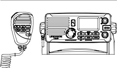
1-6 Basic Operation and Key Functions
All possible keys and their functions are listed here. Note that some of the keys may not be available depending on your Lowrance VHF radio model.
|
6 Key handset |
Link-5 base station radio |
|
mic |
|
|
|
|
Key: |
Function: |
|
VOL/PWR |
Volume and Power. |
|
|
Turn clockwise to power on. Continue to turn until a comfortable volume is reached. |
|
VOL/PWR will also adjust the settings of an external speaker, if connected. |
SQL |
Squelch or Threshold Level. |
|
Sets the threshold level for the minimum receiver signal. Turn fully counterclockwise |
|
until random noise is heard, then turn slowly clockwise until the random noise |
|
disappears. Make another 1/4 turn clockwise for best reception in open sea conditions. |
|
In areas of high noise (eg. close to large cities) reception may improve if sensitivity is |
|
reduced. Either turn SQL slowly clockwise or use the LOCAL setting. See section 2.3. |
16 / 9 |
Priority Channel. |
|
Also on the handset mic. Press to cancel all other modes and to tune into the priority |
|
channel. Press again to return to your original channel. The default Priority Channel is |
|
CH16. |
|
For US models: To make Channel 09 the priority channel, hold down 16/9 until a |
|
beep sounds and 09 is displayed. |
DISTRESS |
Send a DSC Distress Call. |
|
DSC must be active and an MMSI must be programmed. See Section 6. |
PTT |
Press To Talk. |
|
(Located on the handset mic). Press PTT to transmit at any time on an allowable |
|
channel. This automatically exits you from menu mode and stops scanning. You must |
|
release PTT to receive a signal. |
|
If PTT sticks, a built-in timer will automatically shut down a transmission after five |
Lowrance - Link-5 Operation and Installation Instructions |
9 |
|
minutes and sound a short error beep. |
PUSH TO |
|
SELECT |
Enter (ENT). |
|
Use ENT when navigating menus, to confirm entries and edits. |
ACCEPT |
Received DSC Call mode: Press to change immediately to the requested channel |
OPT |
Received Individual Call mode: Press to view any incoming individual call reply |
|
options |
|
Send DISTRESS Call mode: Press to view and select any available options |
ACK |
Receive Individual Call, LL Request, DSC Test Call, or Distress relay (US only) mode: |
|
Press to acknowledge an incoming call when an ACK is requested |
EXIT |
Escape (ESC). |
|
Use EXIT when navigating menus, to clear incorrect entries, to exit from a menu |
|
without saving changes, and to back up to the previous screen. |
QUIT |
DSC Call mode only: Press to return to the previous screen |
CALL |
DSC Call Menu. |
|
Press to enter the DSC Call Menu and make DSC calls. See Section 6. |
RESEND |
DISTRESS CALL mode only: Press to resend a distress alert again |
MENU |
Radio and DSC Setup Menu. |
|
Press to enter the DSC Setup Menu and to customize your radio. See Section 2-5. |
WX |
Weather Channel. |
|
For US models: In USA and Canadian waters, press to hear the most recently selected |
|
weather station. The WX symbol is displayed on the LCD. Rotate the dial or + / - on the |
|
handset mic to change to a different weather channel. Press WX again to return to the |
|
most recent channel. If the weather alert mode (ALT) is ON and an alert tone of |
|
1050 Hz is broadcast from the weather station, it is picked up automatically and the |
|
alarm sounds. Press any key to hear the weather alert voice message. |
|
For all other models: The Wx key can be programmed to a weather channel of your |
|
choice. Select a channel you wish to use as your weather channel, then press and hold |
|
the Wx key for a few seconds. The radio will beep to confirm your choice. You now |
|
have quick access to your favourite channel by pressing the Wx key. |
INFO |
DISTRESS CALL mode only: Press to review distress call information. |
3CH |
Three Favourite Channels. |
|
Also on the handset mic. Press to toggle between your favourite channels. The CH1, |
|
CH2, or CH3 symbol appears on the LCD to show which favourite channel is selected. |
|
To scan only one of your favourite channels, press 3CH then immediately press |
|
and release SCAN. If you want to scan all three favourite channels, press 3CH then |
|
immediately press and hold SCAN. |
|
To add a favourite channel for the first time, select that channel then hold 3CH to store |
|
it in the CH1 location. Repeat the procedure to store two more favourite channels in |
|
the CH2 and CH3 locations respectively. |
|
If you try and add another favourite channel it will overwrite the existing CH3. CH1 |
10 |
Lowrance - Link-5 Operation and Installation Instructions |
|
and CH2 remain unless you delete them. |
||
|
To delete a favourite channel, select that channel then hold down 3CH until the CH1, |
||
|
CH2 or CH3 symbol disappears off the LCD. |
||
PAUSE |
DISTRESS CALL mode only: Pause the automated distress alert resend countdown |
||
|
timer. |
||
SCAN |
Scan. |
||
|
Press to scan between your current channel and the priority channel in DUAL or |
||
|
TRI WATCH mode. The weather channel is also scanned if the USA channel bank is |
||
|
selected and the weather alert mode (ALT) is ON. |
||
|
Hold down SCAN to enter ALL SCAN mode where the priority channel is checked |
||
|
every 1.5 seconds. |
||
|
|
||
|
When a signal is received, scanning stops at that channel and |
BUSY |
appears on |
|
|
||
|
the screen. If the signal ceases for more than 5 seconds, the scan restarts. |
||
|
Press ENT to temporarily skip over (lock out) an “always busy” channel when in ALL |
||
|
SCAN mode and resume the scan. If a channel is skipped, the word ‘SKIP ON’ will |
||
|
momentarily replace the channel name shown on the LCD to designate a skipped |
||
|
channel. The channel name will then have ‘ *’ appended to the end of the channel |
||
|
name. Note that it is not possible to skip over the priority channel. |
||
|
To cancel a skipped channel, select the channel while in normal mode (non-scan |
||
|
mode) then press the ENT key - ‘SKIP OFF’ will be displayed momentarily and the |
||
|
channel will be restored. Alternatively, you can re-power the radio. |
||
|
Press SCAN to stop at the current channel. |
||
|
Press EXIT to cancel scan mode and return to normal operation. |
||
DISTR. CANCEL |
DISTRESS CALL mode only: Press to send a distress cancel call. |
||
Rotary knob |
Channel Select. |
||
|
Turn to select a channel. The current channel is shown on the LCD in BIG digits and an |
||
|
A or B designator suffix (if applicable) in small letters below the channel number. |
||
|
See Appendix C for a complete listing of channel charts. |
||
|
Push to activate the ENT function. |
||
|
You can also use the rotary knob for alphanumeric entry. Turn to step through |
||
|
alphanumeric characters one at a time, then push to confirm each selection. If you |
||
|
make an error, select the < character then push to backup. |
||
SILENCE |
DSC Call mode only: Rotate the rotary knob to silence the call alert when a DSC call is |
||
|
received. |
||
+ / - |
Channel Select. |
||
|
(Located on the handset mic). The current channel is shown on the screen in BIG digits |
||
|
with an appropriate designator suffix A or B in small letters below the channel number. |
||
|
Press + or - to step through the available channels one at a time, or hold down to |
||
|
scroll rapidly through all the available channels. |
||
|
See Appendix C for a complete listing of channel charts. |
||
Lowrance - Link-5 Operation and Installation Instructions |
11 |
Alphanumeric Entry.
This key can be used for both menu selection and for alphanumeric entry. Press + or - to scroll the cursor up or down to menu options when navigating menus.
When editing an item containing only numbers, press - to count through the numbers or hold down to scroll rapidly.
To enter a character, press + to step through the alphabet or hold down to scroll rapidly.
H/L |
Transmission Power. |
||||||
|
(Located on the handset mic). High (HI) 25 W or Low (LO) 1 W. Press to toggle between |
||||||
|
high or low transmission power for the entire channel bank. The HI or LO selection is |
||||||
|
shown on the LCD. |
||||||
|
Some channels allow only low power transmissions. Error beeps will sound if the |
||||||
|
power transmission setting is incorrect. |
||||||
|
Some channels allow only low power transmissions initially, but can be changed to |
||||||
|
high power by holding down H/L and PTT at the same time. |
||||||
|
See Appendix C for a complete listing of channel charts. |
||||||
|
|
|
|
|
|
|
|
|
|
|
|
|
|
|
|
|
|
|
|
|
|
|
|
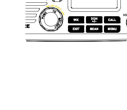
INFO |
PAUSE |
RESEND |
ACCEPT/OPT/ACK/ENT |
QUIT |
DISTR CANCEL |
Close-up of the Link-5 base station radio, showing the keys
12 |
Lowrance - Link-5 Operation and Installation Instructions |
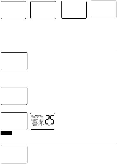
Section 2 - The Radio Menu (MENU)
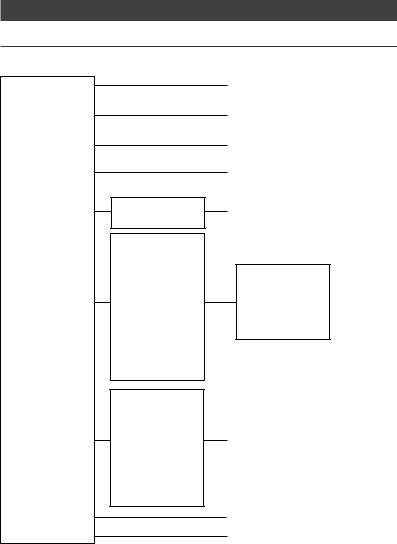
2-1 Radio Menu Options (Menu)
The following options are available through the MENU key:
BUDDY LIST LOCAL/DIST BACKLIGHT CONTRAST
GPS/DATA
DSC SETUP
RADIO SETUP
GPS SIM
RESET
* Model dependant
MANUAL
SETTING
USER MMSI GROUP SETUP ATIS MMSI * ATIS FUNC * INDIV REPLY DSC FUNC
LL REPLY AUTO SWITCH TEST REPLY TIMEOUT
UIC *
CH NAME RING VOLUME KEY BEEP
INT SPEAKER WATCH MODE * WX ALERT * COM PORT
Maintain your buddy list.
See Section 2-2.
Set radio sensitivity.
See Section 2-3.
Set backlight level.
See Section 2-4.
Set contrast level.
See Section 2-4.
Set position & UTC manually.
See Section 2-5.
Set local time and time format.
See Section 2-5.
DSC Setup Menu.
See Section 4.
Make DSC calls.
See Section 5.
Radio Setup Menu.
See Section 3.
Turn the GPS Simulator on/off.
See Section 2-6.
Reset factory settings.
See Section 2-7.
Sections 1-3 and 1-4 explain how to navigate around the menu and enter, save and change data.
Lowrance - Link-5 Operation and Installation Instructions |
13 |

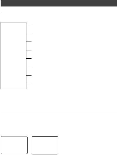
2-2 Maintain Your Buddy List (BUDDY LIST)
MENU SELECT ►BUDDY LIST LOCAL/DIST BACKLIGHT ▼
2-2-1 Add an Entry
Use the Buddy List to store the names and associated MMSI’s of 20 favourite people. Names are stored in the order of entry, with the most recent entry shown first.
The following sections show how to add, edit, and delete entries on your BUDDY LIST. Section 5 explains how to call a buddy.
BUDDY LIST |
ENTER |
NAME |
ENTER NAME |
BOB |
►MANUAL NEW |
–––––––––––– |
BOB |
123456789 |
|
ALEX |
ENTER |
MMSI |
ENTER MMSI |
►STORE |
TOM |
––––––––– |
123456789 |
CANCEL |
|
|
|
|
||
1.Select BUDDY LIST. The cursor is at MANUAL NEW. Press ENT.
2.Enter the buddy name, one character at a time (this may be alphanumeric) then press ENT repeatedly until the cursor moves to the MMSI entry line.
3.Enter the MMSI associated with that buddy name (this must be numeric) then press ENT. If the MMSI is for a Coast Station, enter the 7 digits then press ENT twice.
4.The new buddy name and MMSI are displayed. Press ENT to store the new entry, which is displayed at the top of your buddy list.
Note: When the BUDDY LIST is full (20 entries), you can make a new entry and the buddy at the end of the list is automatically erased.
2-2-2 Edit an Entry
BUDDY LIST |
ALEX |
EDIT NAME |
ALEX |
►MANUAL NEW |
►EDIT |
ALEX |
111223344 |
ALEX |
DELETE |
EDIT MMSI |
►STORE |
TOM |
|
112233445 |
|
|
CANCEL |
1.Select BUDDY LIST. Press ENT to display the list of entries.
2.Scroll down (if required) to the entry and press ENT.
3.Select EDIT. The cursor is at the first character of the name.
4.Edit the buddy name or, to edit only the MMSI, press ENT repeatedly until the cursor moves to the MMSI line.
5.When you are finished, press ENT (repeatedly if necessary) to display the next screen.
6.Press ENT to store the changes. The buddy list is displayed again. If more changes are required, repeat Steps 2 through 6. Otherwise, press EXIT to cancel.
14 |
Lowrance - Link-5 Operation and Installation Instructions |
2-2-3 Delete an Entry
BUDDY LIST |
BUDDY LIST |
TOM |
DELETE BUDDY |
►MANUAL NEW |
MANUAL NEW |
EDIT |
TOM |
ALEX |
ALEX |
►DELETE |
►YES |
TOM |
►TOM |
|
NO |
|
|
1.Select BUDDY LIST. Press ENT to display the list of entries.
2.Scroll down (if required) to the entry you want to delete and press ENT.
3.Select DELETE then select YES.
4.The entry is deleted immediately and the buddy list is displayed again.
2-3 Local or Distance Sensitivity (LOCAL/DIST)
MENU SELECT BUDDY LIST ►LOCAL/DIST BACKLIGHT ▼
Use LOCAL/DIST to improve the sensitivity of the receiver either locally (LOCAL) or over distances (DIST).
LOCAL is not recommended for use in open sea conditions. It is designed for use in areas of high radio noise; for example, close to cities.
See also SQL (Squelch Control) in Section 1.6.
2-3-1 Set DISTANT Sensitivity
SENSITIVITY |
1. |
Select LOCAL/DIST then select DIST. |
|
|
|
►DISTANT |
2. |
Press ENT to activate the DIST setting. This disables local |
LOCAL |
|
sensitivity and the menu is displayed again. |
|
|
2-3-2 Set LOCAL Sensitivity
SENSITIVITY
DISTANT ►LOCAL
1.Select LOCAL/DIST then scroll to LOCAL.
2.Press ENT to activate the LOCAL setting. This disables distance sensitivity and the menu is displayed again.
LOCAL is displayed on the LCD as a reminder that local sensitivity is selected.
2-4 Backlighting (BACKLIGHT) and Contrast (CONTRAST)
MENU SELECT LOCAL/DIST▲ ►BACKLIGHT CONTRAST ▼
Use BACKLIGHT to set the backlight levels for the LCD, keypad and microphone keypad to a comfortable level.
Use CONTRAST to set the contrast level for the LCD.
Lowrance - Link-5 Operation and Installation Instructions |
15 |

2-4-1 Set the Backlighting Level
BACKLIGHT |
1. |
Select BACKLIGHT. |
|
2. |
Select a comfortable backlight level using + or - to change |
||
▀ ▀ ▀ ▀ |
|||
LO |
HI |
the setting. |
|
PRESS ENT |
3. |
Press ENT to enable the setting and return to the menu. |
|
|
Note: The DISTRESS key backlighting cannot be switched off.
2.4.2 Set the Contrast Level
CONTRAST |
1. |
Select CONTRAST. |
|
|
|
▀ ▀ ▀ ▀ |
2. |
Select a comfortable contrast level using + or - to change the |
LO |
HI |
setting. |
PRESS ENT |
|
|
|
3. |
Press ENT to enable the setting and return to the menu. |
2-5 GPS Data and Time (GPS/DATA)
MENU SELECT BACKLIGHT ▲
CONTRAST
►GPS/DATA ▼
If the boat has an operational GPS navigation receiver, the VHF radio automatically detects and updates the vessel position and the local time.
However, if the GPS navigation receiver is disconnected or absent, you can specify the vessel position and the local time manually, using the GPS/DATA option.
This information is important because it will be used if a DSC distress call is transmitted.
You can also select GPS Alert and GPS Simulator options.
2-5-1 Manually Enter Position and UTC Time (MANUAL)
Note that this function is available only if an operational GPS receiver is not connected.
GPS/DATA |
MANUAL LL |
PORT OPS |
►MANUAL |
––’––.–––'N |
10:12AM UTC |
SETTING |
–––’––.–––'E |
M27’52.023'N |
|
MAN ––:––UTC |
082’31.135'W |
1.Select GPS/DATA, then MANUAL.
2.Enter the latitude, then the longitude, then the UTC.
3.Press ENT when all the information is correct.
The vessel’s latitude and longitude are shown on the screen, with the UTC time. The prefix M indicates a manual entry. The manual entries are cancelled if a real GPS position is received.
16 |
Lowrance - Link-5 Operation and Installation Instructions |

2-5-2 Local Time (TIME OFFSET)
The local time can be set by entering the time offset between UTC and local time as follows.
GPS/DATA |
SETTING |
TIME OFFSET |
MANUAL |
►TIME OFFSET |
►+01:30 |
►SETTING |
TIME FORMAT |
|
|
TIME DISPL▼ |
02:30PM LOC |
1.Select GPS/DATA, then SETTING.
2.Select TIME OFFSET to enter the difference between UTC and local time. 15 minute increments can be used with a maximum offset of ±13 hours.
In this example, a difference of +1.5 hours has been entered and the local time is displayed with the suffix LOC.
LM Y X W V U T S R Q P O N Z A B C D E F G H I K L M Y |
|
||||||||||||||||||||||||||
|
|
|
|
|
|
|
|
S |
Q |
§ |
Z |
|
A |
|
|
|
|
G |
|
|
|
|
K |
|
|
|
|
|
|
|
|
|
|
|
|
|
|
|
|
|
|
|
|
|
|
|
|
|
|
|
|
||||
|
|
|
|
|
|
|
T |
|
R |
|
N |
|
|
|
C |
|
|
|
|
|
|
|
|
|
|
|
|
|
|
|
|
|
|
|
|
|
|
|
|
|
|
|
|
|
|
|
|
|
|
|
|
|
|
||
L |
|
|
|
V |
|
|
|
S |
|
P |
|
Z |
A B |
|
|
|
G |
|
I |
|
K |
L |
|
|
|
||
|
|
|
|
|
|
|
|
|
|
|
|
|
|
|
|
|
|
|
|
|
|||||||
|
|
|
|
|
|
|
|
|
|
|
|
E |
|
|
|
|
|
|
|
|
|
||||||
|
|
|
|
|
|
|
|
|
|
|
|
Z |
|
C |
|
|
H |
|
|
|
|
|
|
|
|
||
|
W |
|
|
U |
|
T |
|
Q |
|
|
|
|
|
|
|
|
|
|
K |
|
|
|
|
||||
|
|
|
|
|
|
|
|
|
|
F |
|
|
|
|
|
|
|
|
|
|
|||||||
|
Line Date International |
|
|
|
|
|
|
R |
P* |
|
A |
B |
|
E |
|
|
|
|
|
|
|
L |
|
|
|
||
|
|
|
|
|
|
|
|
|
|
|
|
|
|
|
|
|
|
|
|
|
|
|
|
||||
|
|
|
|
|
|
|
S |
|
|
|
|
|
D |
|
|
|
|
|
|
|
|
|
|
|
|
||
|
|
|
|
|
U |
|
R |
|
Z |
Z |
B |
|
|
|
|
|
H |
|
I |
|
I |
|
|
|
|
||
|
|
|
|
|
T |
|
|
|
|
|
|
|
|
|
|
|
|
|
|||||||||
|
X |
|
|
|
|
|
|
|
|
|
|
C* |
D* |
|
|
|
|
|
|
|
|
||||||
|
|
|
|
|
|
|
|
|
|
|
|
|
E† |
|
|
|
|
|
|
|
|
X |
|
||||
|
|
|
|
|
|
|
|
R |
|
|
|
B |
|
|
E |
|
|
|
I |
|
|
|
|
|
|||
|
|
W |
|
|
|
|
|
|
|
|
C |
D |
F |
|
|
H |
|
|
|
|
InternationalLine Date |
MAPWORLD |
|||||
|
|
|
|
|
|
|
Q |
|
|
Z |
|
E* |
F* |
|
|
|
|
|
|
||||||||
|
|
|
|
|
|
|
R |
|
N |
A |
|
|
|
|
|
|
|
|
|||||||||
|
|
|
|
|
|
|
|
|
|
|
G |
|
|
|
K |
|
|
||||||||||
|
|
|
|
|
|
|
S |
|
|
|
|
C |
|
C |
|
|
|
|
|
|
M |
|
|||||
M |
|
|
|
|
|
|
R Q* |
|
|
|
|
|
E* |
H |
|
|
|
M |
|||||||||
|
M† |
|
|
|
|
|
|
|
Z |
|
|
|
E |
H |
|
|
|
|
|||||||||
|
|
M* |
|
|
V* |
|
|
S |
|
|
|
A |
|
C |
D |
|
|
G |
|
|
|
|
K |
|
|
|
OF |
|
|
|
|
|
|
|
Q |
|
O |
B |
|
F |
|
|
|
I |
|
|
I K |
L |
|
|
|||||
L |
|
|
X |
W |
|
|
|
|
C |
|
|
|
G |
I |
|
L |
|
||||||||||
M |
|
|
|
|
|
P |
|
Z |
A |
|
|
F* |
H |
|
|
|
|
M |
TIME |
||||||||
|
|
|
|
|
|
|
|
|
|
|
|
|
|
|
|
|
|
||||||||||
|
|
|
W |
|
|
|
|
|
|
|
O |
|
C |
|
|
|
|
|
|
L |
|
|
|||||
|
|
M* |
|
|
|
|
|
|
|
|
|
D |
|
|
|
|
|
|
|
|
|
M* |
|||||
|
|
|
W |
U |
|
|
|
|
|
|
|
|
|
|
|
|
H |
I* |
|
|
|
||||||
|
|
|
|
|
S |
|
|
|
|
|
|
|
|
|
|
|
|
|
|
|
|
ZONES |
|||||
|
|
|
|
|
|
|
Q |
|
|
|
B |
|
|
|
|
|
|
K |
|
* |
|
||||||
|
M |
|
|
|
|
|
|
|
|
|
|
|
|
|
|
|
|
|
|
|
|
||||||
|
|
|
|
|
|
|
P |
|
|
Z |
|
|
|
|
|
|
|
|
|
|
* |
L |
M |
||||
|
|
|
|
|
|
|
|
|
|
|
|
|
|
|
|
|
|
|
|
|
|
K |
|
||||
|
|
M |
|
|
|
|
|
|
|
|
|
|
|
|
|
|
|
|
|
|
|
|
K |
|
|
M |
|
|
|
STANDARD TIME ZONES |
|
Q |
|
|
|
|
|
|
|
|
|
|
|
|
M |
|
|
||||||||
|
|
|
|
Standard Time |
= Universal Time – value from table |
|
|
|
|
|
|
||||||||||||||||
|
|
|
|
O |
|
|
|
|
|
|
|||||||||||||||||
|
|
|
Corrected to January 2011 |
|
|
|
Universal Time |
= Standard Time + value from table |
|
|
|
|
|
|
|
|
|||||||||||
|
Zone boundaries are approximate |
|
|
|
h m |
h m |
|
h m |
|
h m |
|
h m |
|
h m |
|
h m |
|
|
||
|
Daylight Saving Time (Summer Time), |
|
Z |
0 |
D* – 4 |
30 |
G |
– 7 |
L |
–11 |
N |
+ 1 |
Q* + 4 30 |
V |
+ 9 |
|
|
|||
usually one hour in advance of Standard |
|
A |
– 1 |
E – 5 |
|
H |
– 8 |
L* |
–11 30 |
O |
+ 2 |
R |
+ 5 |
V* |
+ 9 30 |
|
|
|||
|
B |
– 2 |
E* – 5 |
30 |
I |
– 9 |
M |
–12 |
P |
+ 3 |
S |
+ 6 |
W |
+10 |
|
|
||||
|
Time, is kept in some places |
|
|
|
|
|||||||||||||||
|
|
|
C |
– 3 |
E† – 5 |
45 |
I* |
– 9 30 |
M |
–12 45 |
P* + 3 30 |
T |
+ 7 |
X |
+11 |
|
|
|||
|
|
|
|
|
§ |
|
||||||||||||||
|
Map outline © Mountain High Maps |
|
C* – 3 30 |
F – 6 |
|
K |
–10 |
M* –13 |
Q + 4 |
U |
+ 8 |
Y |
+12 |
|
||||||
Compiled by HM Nautical Almanac Office |
P |
D |
– 4 |
F* – 6 |
30 |
K* –10 30 |
M† –14 |
§ No Standard Time legally adopted |
|
|
||||||||||
180° |
150°W |
120°W |
90°W |
60°W |
30°W |
0° |
|
|
30°E |
|
60°E |
|
90°E |
120°E |
150°E |
180° |
||||
2-5-3 Time Format Options (TIME FORMAT)
Time can be shown in 12 or 24 hour format.
GPS/DATA |
SETTING |
TIME FORMAT |
MANUAL |
TIME OFFSET |
►12 Hr |
►SETTING |
►TIME FORMAT |
24 Hr |
|
TIME DISPL▼ |
07:15AM LOC |
Lowrance - Link-5 Operation and Installation Instructions |
17 |

1.Select GPS/DATA, then SETTING.
2.Select TIME FORMAT.
3.Select 12 Hr or 24 Hr as desired. In this example, 12 hour format has been selected and the LCD shows the AM or PM suffix.
2-5-4 Time Display Options (TIME DISPLAY)
If you have entered the time manually as described in the previous sections, the time is always shown on the screen with the prefix M.
However, if the vessel position is being updated through a GPS navigation receiver, you can switch the time display on the screen ON or OFF as follows:
SETTING |
TIME DISPLY |
TIME OFFSET |
►ON |
TIME FORMAT |
OFF |
►TIME DISPL▼ |
|
1.Select GPS/DATA, then SETTING.
2.Select TIME DISPLAY.
3.Select ON (on) or OFF (off ) as desired. In this example, OFF has been selected and the screen no longer shows the time.
If the time display is set ON, course and speed data are not displayed on the LCD (see section 2-5-6).
2-5-5 Position Display Options (LL display)
If you have entered the vessel position manually as described in the previous section, the vessel position is always shown on the screen with the suffix M.
However, if the time is being updated through a GPS navigation receiver, you can switch the vessel position display on the screen on or off as follows:
SETTING |
LL DISPLAY |
TIME FORMA▲ |
►ON |
TIME DISPLY |
OFF |
►LL DISPLY ▼ |
|
1.Select GPS/DATA, then SETTING.
2.Select LL DISPLAY.
3.Select ON (on) or OFF (off ) as desired. In this example, OFF has been selected and the screen no longer shows the vessel position.
2-5-6 Course & Speed Display Options (COG/SOG)
Use this option to display course over ground (COG) and speed over ground (SOG) data on the screen.
1. Select GPS/DATA, then SETTING.
SETTING |
COG/SOG |
TIME DISPL▲ |
►ON |
LL DISPLY |
OFF |
►COG/SOG ▼ |
|
2.Select COG/SOG.
3.Select ON (on) or OFF (off ) as desired. In this example, ON has been selected and the screen shows the bearing and speed.
If COG/SOG is set ON (on), the time is not displayed on the screen (see section 2-5-4).
18 |
Lowrance - Link-5 Operation and Installation Instructions |

2-5-7 GPS Alert Options (ALERT)
The GPS alert is usually set to ON (on) so that if the GPS navigation receiver is disconnected, the alarm sounds.
SETTING |
GPS ALERT |
LL DISPLY ▲ |
►ON |
COG/SOG |
OFF |
►GPS ALERT |
|
1.Select GPS/DATA, then SETTING.
2.Select GPS ALERT.
3.Select ON (on) or OFF (off ) as desired.
2-6 GPS Simulator (SIMULATOR)
The GPS Simulator is set to OFF whenever the radio is switched ON, or whenever real GPS data is available through the COM port. However, if you want to test it, turn it on.
MENU SELECT DSC SETUP ▲ RADIO SETUP ►GPS SIM ▼
1.Select GPS SIM, then select ON (on) or OFF (off ) as desired.
Whenever the GPS Simulator is turned ON (on), simulated Speed Over Ground (SOG), Course Over Ground (COG), and LL position appear on the screen. This data is updated automatically during the simulation.
Important: It is not possible to send a DSC transmission when in Simulator mode.
2-7 Reset to Factory Defaults (RESET)
Use this setting to return every setting to the factory defaults except all MMSI settings, entries in your buddy list and any edited channel names.
MENU |
SELECT |
RESET RADIO |
RADIO SETU▲ |
ARE YOU SURE |
|
GPS |
SIM |
►YES |
►RESET |
NO |
|
1.Select RESET. The radio asks for confirmation.
2.Select YES to reset the radio and return to the menu.
Lowrance - Link-5 Operation and Installation Instructions |
19 |
Section 3 - Radio Setup Menu (RADIO SETUP)
3-1 Radio Setup Menu (RADIO SETUP)
The following options are available through MENU key:
UIC *
CH NAME
RING VOLUME
KEY BEEP
INT SPEAKER
WATCH MODE *
WX ALERT *
COM PORT
* Model dependant
Channel band.
See Section 3-2.
Edit or delete channel names.
See Section 3-3.
Set the volume level of the incoming call notification beeps.
See section 3-4.
Set the volume level of the beeps.
See section 3-4.
Switch ON/OFF (on/off ) the radio’s internal speakers.
See section 3-5.
Selects Priority Channel operation with Dual or Tri watch scanning.
See section 3-6.
Selects if the WX Alert scanning mode is ON (on) or OFF (off ).
See section 3-7.
Select NMEA protocol for communications between the VHF radio and any other instruments.
See section 3-8.
Sections 1-3 and 1-4 explain how to navigate around the menu and enter, save and change data.
3-2 Channel (UIC)
Note: UIC may not be available on all models.
Toggle between USA, International or Canadian channel banks. The selected channel bank is displayed on the LCD along with the last used channel. All the channel charts are shown in Appendix C.
RADIO SETUP |
UIC |
►UIC |
►USA |
CH NAME |
INT’L |
RING VOLUM▼ |
CANADA |
20 |
Lowrance - Link-5 Operation and Installation Instructions |
3-3 Channel Names (CH NAME)
The channel charts are listed in Appendix C with their default name tags. CH NAME gives you the option to edit or delete the channel name tags displayed on the screen.
RADIO SETUP |
01 |
TELEPHONE |
►CH NAME |
►EDIT |
|
RING VOLUME |
CH NAME |
DELETE |
KEY BEEP ▼ |
TELEPHONE |
|
EDIT CH NAME |
EDIT CH NAME |
|
TELEPHONE |
PHONE1 |
|
|
►YES |
|
|
NO |
|
1.Select RADIO SETUP, then CH NAME.
2.Use + or - to step through the channels with their name tags until you see the channel name tag you want to change, then press ENT. In this example, the channel name TELEPHONE associated with channel 01 is being changed to PHONE1.
3.Select EDIT and press ENT to edit the existing name tag. Input the new name over the existing name. It can be a maximum of 12 characters.
To delete the channel name, select DELETE and press ENT.
4.Press ENT (repeatedly if necessary) to display the YES/NO confirmation.
5.Press ENT to confirm the new channel name tag or the deletion, then press EXIT to return to the menu.
3-4 RING & BEEP Volume (RING VOLUME) and (KEY BEEP)
Set the volume level of the incoming signal beeps (RING VOLUME) and/or the error and warning beeps (KEY BEEP) to HIGH (high) or LOW (low) as follows:
RADIO SETUP |
RING |
VOLUME |
KEY BEEP |
CH NAME |
►HIGH |
►HIGH |
|
►RING VOLUME |
LOW |
|
LOW |
KEY BEEP ▼ |
|
|
OFF |
1.Select RADIO SETUP, then RING VOLUME or BEEP VOLUME as appropriate.
2.Select a HIGH or LOW volume. (It is possible to turn the beeps off completely by selecting KEY BEEP then OFF.)
3.Press ENT to enable the new volume setting and return to the menu.
3-5 Internal Speaker Connections (INT SPEAKER)
Switch the radio’s internal speaker ON (on) or OFF (off ). The external speaker is always ON (on) if a speaker is plugged into the external speaker jack.
Lowrance - Link-5 Operation and Installation Instructions |
21 |

RADIO SETUP |
INT SPEAKER |
RING VOLUM▲ |
►ON |
KEY BEEP |
OFF |
►INT SPEAKE▼ |
|
1.Select RADIO SETUP, then INT SPEAKER.
2.Select ON (on) or OFF (off ) then press ENT to enable the setting and return to the menu.
3-6 Set the Priority Channel (WATCH MODE)
For EU models, watch mode is similar to a dual watch, scanning between the priority channel CH16 and the working channel. If you have US model and are operating on USA or Canadian channel banks, you can set the priority channel to cover both CH16 and CH09 as well as the working channel, as follows:
RADIO SETUP |
WATCH MODE |
|
KEY |
BEEP ▲ |
►ONLY 16CH |
INT |
SPEAKER |
16CH+9CH |
►WATCH MODE▼
1.Select RADIO SETUP, then WATCH MODE.
2.Select ONLY 16CH for dual watch mode, or 16CH+9CH for tri watch mode.
3-7 Weather Alert (Wx ALERT)
US models ONLY
The NOAA provides several weather forecast channels on USA and Canadian channel banks. If severe weather such as storms or hurricanes are forecast, the NOAA broadcasts a weather alert on 1050 Hz. You can set up the radio to pick up weather alerts, as follows:
RADIO SETUP |
WX ALERT |
INT SPEAKE▲ |
ON |
WATCH MODE |
►OFF |
►WX ALERT ▼ |
|
1.Select RADIO SETUP, then WX ALERT.
2.Select ON (on) or OFF (off ) then press ENT to enable the setting and return to the menu.
When a weather alert is broadcast, the alarm will sound. Press any key to hear the weather alert voice message.
3-8 NMEA protocol (COM PORT)
This radio uses NMEA0183 protocol to receive GPS data from a compatible GPS unit. The COM Port must be configured correctly before use. The radio can be added to a group of instru-
ments using NMEA protocol.
RADIO SETUP |
NMEA |
WATCH MODE▲ |
CHECKSUM |
WX ALERT |
►ON |
►COM PORT |
OFF |
1.Select RADIO SETUP, then COM PORT.
2.Select CHECKSUM ON (on) or OFF (off ) then press ENT to enable the setting and return to the menu.
CHECKSUM ON is the default setting.
The COM Port uses 4800 baud rate and can receive the following GPS data sentence: RMC, GGA, GLL, GNS. Additionally, this radio will output the following NMEA DSC data: DSC (for DSC call), DSE ( for enhanced position).
22 |
Lowrance - Link-5 Operation and Installation Instructions |
Loading...