


Lowrance 5 HDI, 5 TS, 7X GPS TS, 7 HDI, 7 TS Operator Manual
...
Hook2 Series
Operator Manual
5 HDI, 5TS, 7X GPSTS, 7 HDI, 7TS, 9TS, 9 HDI, and 12TS
ENGLISH
www.lowrance.com

Preface
Disclaimer
As Navico is continuously improving this product, we retain the right to make changes to the product at any time which may not be reflected in this version of the manual. Please contact your nearest distributor if you require any further assistance.
It is the owner’s sole responsibility to install and use the equipment in a manner that will not cause accidents, personal injury or property damage. The user of this product is solely responsible for observing safe boating practices.
NAVICO HOLDING AS AND ITS SUBSIDIARIES, BRANCHES AND AFFILIATES DISCLAIM ALL LIABILITY FOR ANY USE OF THIS PRODUCT IN A WAY THAT MAY CAUSE ACCIDENTS, DAMAGE OR THAT MAY VIOLATE THE LAW.
Governing Language: This statement, any instruction manuals, user guides and other information relating to the product (Documentation) may be translated to, or has been translated from, another language (Translation). In the event of any conflict between any Translation of the Documentation, the English language version of the Documentation will be the official version of the Documentation.
This manual represents the product as at the time of printing. Navico Holding AS and its subsidiaries, branches and affiliates reserve the right to make changes to specifications without notice.
Trademarks
Lowrance® and Navico® are registered trademarks of Navico Holding AS.
C-MAP® is a registered trademark of C-MAP. Navionics® is a registered trademark of Navionics, Inc.
SD™ and microSD™ are trademarks or registered trademarks of SD-3C, LLC in the United States, other countries or both.
Additional mapping data: Copyright© 2012 NSI, Inc.: Copyright© 2012 by Richardson’s Maptech.
Preface | Hook² Series Operator Manual |
|
3 |
|
Navico product references
This manual can refer to the following Navico products:
•DownScan Imaging™ (DownScan)
•DownScan Overlay™ (Overlay)
•StructureMap™ (StructureMap)
•StructureScan® (StructureScan)
Copyright
Copyright © 2017 Navico Holding AS.
Warranty
The warranty card is supplied as a separate document.
In case of any queries, refer to the brand website of your display or system: www.lowrance.com.
Compliance statements
This equipment complies with:
•CE under 2014/53/EU Directive
•The requirements of level 2 devices of the Radio communications (Electromagnetic Compatibility) standard 2008
The relevant Declaration of Conformity is available in the product's section at the following website: www.lowrance.com.
About this manual
This manual is a reference guide for operating the following Hook2models: 5 HDI, 5 TS, 7X GPS TS, 7 HDI, 7 TS, 9 TS, 9 HDI, and 12 TS. As a result, screenshots of menus and dialogs may not match the look of your unit.
These units are only capable of the sonar views and frequencies indicated in the specification included in the transducer’s installation guide for the transducer provided with the unit. The model is provided on the front of the unit. The following is a list of models, the transducer which should be used and the sonar functionality available.
4 |
|
Preface | Hook² Series Operator Manual |
|

•HDI models: The SplitShot transducer should be used which provides traditional sonar and DownScan functionality.
•TS models: The TripleShot transducer should be used which provides traditional sonar, DownScan and Side/StructureScan functionality.
Transducers added via one of the optional transducer adapter cables will still only have the available views and frequencies that the display is designed to work with. Airmar transducers are not supported via the adapter cable.
In the manual, important text that requires special attention from the reader is emphasized as follows:
ÚNote: Used to draw the reader’s attention to a comment or some important information.
 Warning: Used when it is necessary to warn personnel that they should proceed carefully to prevent risk of injury and/or damage to equipment/ personnel.
Manual version
This manual is written for software version 1.0. The manual is continually updated to match new software releases. The latest available manual version can be downloaded from www.lowrance.com.
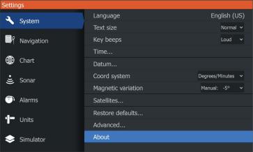
The Software version
The software version currently on this unit can be found in the About dialog. The About dialog is available in the System Settings.
For more information, refer to "About" on page 77.
For upgrading your software, refer to "Software upgrades" on page 81.
Preface | Hook² Series Operator Manual |
|
5 |
|
6 |
|
Preface | Hook² Series Operator Manual |
|

Contents
11 Introduction
11Front controls
12The Home page
13Application pages
15 Basic operation
15 System Controls dialog
15Turning the system on and off
16Display illumination
16 Stop sonar
16Using menus and dialogs
17Using the cursor on the panel
17Creating a Man Overboard waypoint
18Screen capture
19Customizing your system
19Customizing the Home page wallpaper
19Data Overlay
20Adding new custom pages
21Edit or delete custom pages
21 Adjusting the split on multiple panel pages
23 Charts
23The Chart panel
24Selecting chart type
24Vessel symbol
24Chart scale
24Panning the chart
24Waypoints, Routes, and Trails
25Navigating
25Displaying information about chart items
25Find objects on chart panels
26Chart overlay
26Positioning the vessel on the chart panel
27C-MAP specific chart options
28Navionics charts
32 Chart settings
Contents | Hook² Series Operator Manual |
|
7 |
|
34 GPS plotter
34GPS plotter page
35Vessel symbol
35 GPS plotter page scale
35Panning the GPS plotter image
35GPS view options
36Waypoints, Routes, and Trails
36Navigating
37GPS plotter settings
38Waypoints, Routes, and Trails
38 Waypoints, Routes, and Trails dialogs
38 Waypoints
40 Routes
43 Trails
46 Navigating
46Navigate to cursor position
46Navigate to a waypoint
46Navigate a route
47Navigation settings
49 Sonar
49The Sonar image
50Zooming the image
50Viewing history
50Customize the image settings
50Custom and Ice Fishing mode options
53More options
55Start recording sonar log data
56Stop recording sonar log data
57Viewing the recorded sounder data
58Sonar settings
60 StructureScan
60 The StructureScan image
60Zooming the StructureScan image
61Using the cursor on the StructureScan panel
8 |
|
Contents | Hook² Series Operator Manual |
|
61Viewing StructureScan history
62Recording StructureScan data
62 Setting up the StructureScan image
65 DownScan
65 The DownScan image
65 Zooming the DownScan image
65Using the cursor on the DownScan panel
66Viewing DownScan history
66 Customize the image settings
70 StructureMap
70The StructureMap image
70Activating Structure overlay
71StructureMap tips
71 Recording StructureScan data
71Using StructureMap with mapping cards
72Structure options
73Alarms
73 Alarm system
73 Type of messages
73 Alarm messages
73 Acknowledging a message
74 Alarms dialog
75 |
Tools |
75 |
Settings |
78 |
Waypoints/routes/trails |
78 |
Info |
78 |
Storage |
80 Maintenance
80Preventive maintenance
80Cleaning the display unit
80Checking the connectors
81Service assistant
81Software upgrades
82Backing up your system data
Contents | Hook² Series Operator Manual |
|
9 |
|
85 Simulator
85 Demo mode
85Simulator source files
86Advanced simulator settings
10 |
|
Contents | Hook² Series Operator Manual |
|
1 |
Introduction |
Front controls |
1


 2
2
3
4 


 5
5
6 


 7
7
1Pages - Press to activate the Home page.
2Zoom in/out - Press to zoom the image.
Press both keys simultaneous to create a MOB (Man Over Board) waypoint at the vessel's position.
ÚNote: Creating a MOB waypoint is not available on 4x Sonar only models.
3Arrows - On any full screen page: press to position the cursor on the image. Press to pan the image in any direction. On multiple panel pages: press to select a panel.
In menus and dialogs: press to highlight an option.
4Exit (X) - On a maximized multiple panel page: press to return to the multiple panel page.
In menus and dialogs: press to return to previous menu level and to exit a dialog.
5Menu/Enter - On any full screen page with no menu or dialog active: press to display the menu.
On multiple panel pages: press to maximize the current selected panel.
In menus and dialogs: press to confirm a selection.
6Cursor/Waypoint - Press to activate/deactivate the cursor. Press and hold to save a waypoint.
7Power - Press to display the System Controls dialog. Press and hold to power the unit on/off.
Introduction | Hook² Series Operator Manual |
|
11 |
|
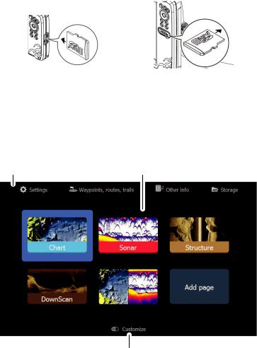
Micro SD card
Depending on model the card reader is located either on the side or on the front.
The Home page
The Home page is accessed from any operation by a short press on the Pages key.
Ú Note: Page icons on the Home page vary with model type.
1 |
2 |
3
1Tools panel - Select a button to access dialogs used for carrying out a task, or for browsing stored information.
12 |
|
Introduction | Hook² Series Operator Manual |
|
2Application page icons - Select a button to display the application page.
3Customize - Activate customize mode to delete or modify custom pages.
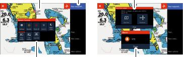
Application pages
1 |
2 |
4 |
3 |
5 |
1Application panel
2Menu - Panel specific menu.
3System Controls dialog - Quick access to basic system settings.
4Dialog - Information to or input from the user.
5Alarm message - Displayed if dangerous situations or system faults occur.
Each application connected to the system is presented on panels.
The application can be presented as a full page, or in combination with other panels in a multiple panel page.
All application pages are accessed from the Home page.
Custom pages
The system is delivered with one preconfigured custom page, and you can create your own. All custom pages can be modified and deleted. To add a custom page, refer to "Adding new custom pages" on page 20.
To edit or delete a custom page, refer to "Edit or delete custom pages" on page 21.
Introduction | Hook² Series Operator Manual |
|
13 |
|
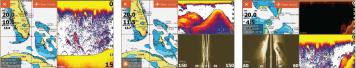
Multiple panel custom pages
You can have up to 4 panels on a custom page. Refer to "Adding new custom pages" on page 20.
2 panels page |
3 panels page |
4 panels page |
Panel sizes in a multiple panel page can be adjusted from the System Controls dialog. Refer to "Adjusting the split on multiple panel pages" on page 21.
•With cursor not active on any panel, switch active panel by using the Arrow keys. An active panel is indicated with an orange border.
•Maximize the active panel by pressing the Menu/Enter key. Press the Exit (X) key to go back to the multiple panel page.
•To display the panel menu, it must first be maximized. Once maximized, press the Menu/Enter key (again) to display the menu for the maximized pane. Press the Exit (X) key to close the menu, press the Exit (X) key again to go back to the multiple panel page.
•Activate the cursor on the active or maximized panel by pressing the Cursor/Waypoint key, then use the Arrow keys to position the cursor. Press the Cursor/Waypoint key again to remove the cursor.
14 |
|
Introduction | Hook² Series Operator Manual |
|

2 |
Basic operation |
|
|
System Controls dialog |
|
The System Controls dialog provides quick access to basic system |
|
settings. You display the dialog by making a short press on the |
|
Power key. |
The icons displayed on the dialog can vary. For example, the adjust splits option is only available if you are viewing a multiple panel page when you open the System Controls dialog.
Activating functions
Select the icon of the function you want to set or toggle on or off. For those functions that toggle on and off, an orange bar across the top of the icon indicates the function is activated, as shown in the Data overlay icon above.
Turning the system on and off
You turn the system on and off by pressing and holding the Power key. You can also turn the unit off from the System Controls dialog.
If the Power key is released before the shut-down is completed, the power off process is cancelled.
Standby mode
In Standby mode, the Sonar and the backlight for screen and keys are turned off to save power. The system continues to run in the background.
You select Standby mode from the System Controls dialog.
Basic operation | Hook² Series Operator Manual |
|
15 |
|

Switch from Standby mode to normal operation by a short press on the Power key.
Display illumination
Brightness
The display backlighting can be adjusted at any time from the System Controls dialog.
You can also cycle the preset backlight levels by short presses on the Power key.
Night mode
The night mode option optimizes the color palette and backlight for low light conditions.
ÚNote: Details on the panel may be less visible when the Night mode is selected.
Stop sonar
Select the Stop sonar option in the System Controls dialog to stop all sonar from pinging. Use the stop sonar option anytime you want to disable all sonar but not power off the unit.
Using menus and dialogs
Menus
The menu is used to operate the system and to adjust settings.
Press the Menu/Enter key to display the page menu. Press the Menu/Enter key again to close the menu.
Use the Arrow keys to highlight a menu option, then press the Menu/Enter key to confirm the selection.
Scroll bars - activate the scroll bar in the menu and use the Arrow keys to adjust it. Press the Menu/Enter key to save your adjustment.
The status of the cursor (active vs. inactive) changes the menu options.
Dialog boxes
Use the Arrow keys to highlight a dialog option, then press the Menu/Enter key to confirm the selection.
16 |
|
Basic operation | Hook² Series Operator Manual |
|
Numeric and alphanumeric keyboards are automatically displayed when required for entering user information in dialogs.
A dialog is closed by saving or cancelling the entry. A dialog can also be closed by pressing the Exit (X) key.
Using the cursor on the panel
The cursor can be used to mark a position, and to select items. By default, the cursor is not shown on the panel.
Display the cursor by pressing the Cursor/Waypoint key and use the Arrow keys to move the cursor on the panel.
When the cursor is active on the chart page, the cursor position window is displayed. The bottom line of the window shows the distance and heading from the vessel to the cursor.
When the cursor is active on the sonar page, the window also shows the depth and temperature at the cursor.
To remove the cursor and cursor elements from the panel, press the Cursor/Waypoint key.
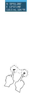
Creating a Man Overboard waypoint
If an emergency situation should occur, you can save a Man Overboard (MOB) waypoint at the vessel’s current position by pressing both the Zoom keys simultaneously.
When you activate the MOB function the following actions are automatically performed:
•A MOB waypoint is created at the vessel’s position
•The display switches to a zoomed panel, centered on the vessel's position
•The cursor is positioned on the MOB waypoint, and navigation information to the MOB waypoint is shown in the cursor information window
Multiple MOB waypoints are saved by repeatedly pressing the zoom keys. The cursor information window continues to show navigation information to the initial MOB waypoint until the cursor is moved or removed from the panel.
Basic operation | Hook² Series Operator Manual |
|
17 |
|
Cancel navigation to MOB
The system continues to display navigational information towards the MOB waypoint until you cancel the navigation from the menu.
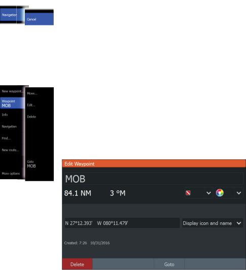
Display MOB waypoint information
You can display MOB information by selecting the MOB waypoint so the MOB waypoint pop-up is displayed. Open the menu and select the Info option in the menu.
The MOB waypoint menu option
When an MOB waypoint is activated, you can use the Waypoint MOB menu option to:
•Move it on the panel
•Edit its attributes
•Delete it
•Goto it
When you select the Edit menu option the Edit Waypoint dialog opens.
Screen capture
Simultaneously press the Pages key and Power key to take a screen capture. Screen captures are saved to internal memory.
To view files, refer to "Files" on page 78.
18 |
|
Basic operation | Hook² Series Operator Manual |
|

3 |
Customizing your system |
|
|
Customizing the Home page wallpaper |
|
The Home page's wallpaper can be customized. You can select one |
|
of the pictures included with the system, or you can use your own |
|
picture in .jpg or .png format. |
The images can be available on any location that can be seen in the files browser. When a picture is chosen as the wallpaper, it is automatically copied to the Wallpaper folder.
Data Overlay
You can have data information as overlay on a page.
Turning Data overlay on and off
You can turn overlay data on or off for any active page by selecting the Data overlay icon on the System Controls dialog. When Data overlay is on, an orange bar appears above the icon.
Customizing your system | Hook² Series Operator Manual |
|
19 |
|
Edit overlay data
Use the Edit overlay option on the System Controls dialog to access edit menu options to:
•Add a new data overlay to the active panel.
•Delete a selected data overlay.
•Change a selected data overlay to display different data.
•Configure a selected data overlay appearance (digital or analog, size, etc.).
•Re-locate an item by selecting it and then the Move menu option. Use the Arrow keys to move selected item.
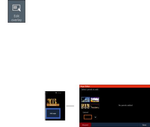
Adding new custom pages
A maximum of 9 pages are allowed. You can have up to 4 panels on a custom page.
1.Select the add page icon on the Home page to open the page editor dialog
2.Use the Arrow keys to highlight a panel, then press the Menu/ Enter key. The panel is added to the page.
3.(Optional) Repeat step 2 to add additional panels. A maximum of 4 panels are allowed.
-To change the layout: use the Arrow keys to select the layout option. Use this option to specify how you want the panels displayed.
-To remove a panel: use the Arrow keys to select the pane on the right side of the dialog and to highlight the delete (X) icon in the top right corner of the panel. Press the Menu/Enter key. The panel is removed from the pane on the right side of the dialog.
-To move a panel: use the Arrow keys to select the pane on the right side of the dialog and to highlight the arrows icon in the
20 |
|
Customizing your system | Hook² Series Operator |
|
||
|
|
Manual |
|
|
top left corner of the panel you want to move. Press the Menu/Enter key. A larger arrows icon is displayed. Use the Arrow keys to move the highlighted panel. Press the Menu/ Enter key to save your adjustment.
4. Save the page layout.
The system displays the new custom page, and an icon for the new page is included on the Home page.
Edit or delete custom pages
1.On the Home page, use the Arrow keys to highlight the customize option and press the Enter/Menu key to turn ON the customize option.
2.Use the Arrow keys to:
-Select the X option on a custom page icon, and press the Menu/Enter key to remove the page
-Select the tool option on a custom page icon, and press the Menu/Enter key to display the page editor dialog
3.Change the layout, add, and remove panels using the custom page editor dialog. Refer to Step 3 in "Adding new custom pages" on page 20.
4.Save or discard your changes to leave edit mode.
Adjusting the split on multiple panel pages
1.Open the multiple panel page
2.Quick-press the Power key to open the System Controls dialog
3.Select the adjust splits option. The cursor arrows icon appears on the multiple panel page.
Customizing your system | Hook² Series Operator Manual |
|
21 |
|
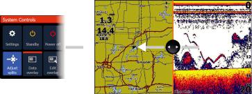
4.Use the Arrow keys to move the split to the desired position
5.Press the Menu/Enter key to save the split adjustment.
22 |
|
Customizing your system | Hook² Series Operator |
|
||
|
|
Manual |
|
|

4 |
Charts |
|
|
Ú Note: Charts are not available on 7x TS models. Instead the GPS |
|
function is available, refer to "GPS plotter" on page 34. |
|
The chart function displays your vessel’s position relative to land |
|
and other chart objects. On the chart panel you can plan and |
navigate routes, and place waypoints.
You can overlay a StructureScan image. Refer to "StructureMap" on page 70.
The Chart panel
1Waypoint*
2Vessel with extension line (extension line is optional)
3Route*
4North indicator
5Grid lines*
6Range rings*
7Trail*
Charts | Hook² Series Operator Manual |
|
23 |
|

8Chart range scale
9Range rings interval (only displayed when Range rings are turned on)
*Optional chart items. You turn the optional chart items on/off individually from the Chart settings dialog.
Selecting chart type
You specify the chart type shown on the Chart panel by selecting one of the available chart types in the chart settings dialog. Refer to
"Chart settings" on page 32.
Vessel symbol
When the system has a valid GPS position lock, the vessel symbol indicates vessel position. If no GPS position is available, the vessel symbol includes a question mark.
Chart scale
You zoom in and out on the chart by using the Zoom keys.
Chart range scale and range rings interval (when turned on) are shown in the lower right corner of the chart panel.
Panning the chart
You can move the chart in any direction by using the Arrow keys to move the cursor to the edge of the chart panel in the desired direction.
To remove the cursor and cursor elements from the panel, press the Cursor/Waypoint key. This also centers the chart to the vessel position.
Waypoints, Routes, and Trails
You can position and manage waypoints, routes and trails on the page. For more information, refer to "Waypoints, Routes, and Trails" on page 38.
24 |
|
Charts | Hook² Series Operator Manual |
|
Navigating
You can use the page for navigating to the cursor, to a waypoint, or navigate a route. Refer to "Navigating" on page 46.
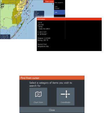
Displaying information about chart items
When you position the cursor over a chart item, waypoint, trail or a route, basic information for the selected item is displayed as a popup.
ÚNote: Pop-up information has to be enabled in chart settings to see basic item information.
Select the info option in the menu to display a list of items near the cursor. Select an item in the list to display all available information for that item.
Find objects on chart panels
Select the find menu option to search for chart items.
Charts | Hook² Series Operator Manual |
|
25 |
|
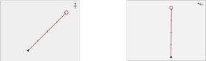
Chart overlay
Structure (StructureMap) information can be displayed as overlay on your chart panel.
ÚNote: Structure overlay (StructureMap) is only available on models that have TripleShot/SideScan capability.
When Structure overlay is selected, the chart menu expands to include basic menu functions for the overlay. Refer to "StructureMap" on page 70.
Positioning the vessel on the chart panel
Chart orientation
You can specify how the chart is rotated in the panel. The chart orientation symbol in the panel’s upper right corner indicates the north direction.
North up |
Course up |
North up
Displays the chart with north upward.
Course up
The chart direction is depending on if navigating or not:
•when navigating: the desired course line is oriented up
•if not navigating: the direction the vessel is actually traveling (COG) is oriented up
Look ahead
Moves the vessel icon on the panel to maximize your view ahead of the vessel.
26 |
|
Charts | Hook² Series Operator Manual |
|
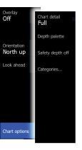
C-MAP specific chart options
Chart overlay, orientation, and look ahead options (previously described in this section) are common to both C-MAP and Navionics charts. The following describe C-MAP specific chart options.
Chart detail
•Full
All available information for the chart in use.
•Medium
Minimum information sufficient for navigation.
•Low
Basic level of information that cannot be removed, and includes information that is required in all geographic areas. It is not intended to be sufficient for safe navigation.
Depth palette
Controls the Depth palette used on the map.
Depth filter
Filters out depth values shallower than the selected depth filter limit.
Safety depth
C-MAP charts use different shades of blue to
distinguish between shallow (lighter shades) and deep (darker shades) water. After enabling Safety depth, specify the
desired safety depth limit. The Safety depth sets the limit at which depths will be drawn without blue shading.
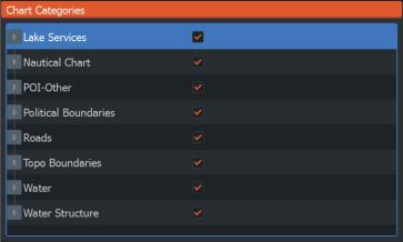
Chart categories
Several categories and sub-categories are included. You can turn on/off the categories individually depending on which information you want to see.
Charts | Hook² Series Operator Manual |
|
27 |
|
Navionics charts
Some Navionics features require the most current data from Navionics. For those features, a message is displayed stating that the feature is unavailable if you do not have the appropriate Navionics charts or chart card inserted. For more information on what is required for these features, refer to www.navionics.com.
You can also get a message if you try to use a restricted feature when the Navionics chart card is not activated. To activate the card, contact Navionics.
28 |
|
Charts | Hook² Series Operator Manual |
|
 Loading...