


HDS-5, HDS-7,
HDS-5m & HDS-7m
Operation Manual

Copyright © 2011 Navico
All Rights Reserved
Lowrance® and Navico® are registered trademarks of Navico.
Fishing Hot Spots® is a registered trademark of Fishing Hot Spots Inc.
Navionics® is a registered trademark of Navionics, Inc.
NMEA 2000® is a registered trademark of the National Marine Electronics Association.
Points of Interest Data in this unit are by infoUSA, copyright© 2001-2010, All Rights Reserved. infoUSA is a trademark of infoUSA, Inc.
Additional mapping data: copyright© 2010 by Transas Ltd.; Copyright© 2010 by Maptech Inc.
Navico may find it necessary to change or end our policies, regulations and special offers at any time. We reserve the right to do so without notice.All features and specifications subject to change without notice.
Software updates for your unit
Occassionally check the Lowrance website for free software upgrades for your unit. Go to www.lowrance.com for the software upgrades. Select the Downloads option from the grey menu bar near the top of the Lowrance website homepage. The Downloads screen will appear. Select Products Software Updates from the list on the left side of the screen. The Products Software Updates screen will appear. Scroll through the Product list and select your unit to download the software update.
IMPORTANT NOTE ABOUT RESTRICTED OPERATION OUTSIDE OF THE AMERICAS
Units designed for sale in the Americas will have limited Language and Units functionality outside of a zone defined as 30 degrees West longitude on the East and the International Date Line on the West. Language options will be restricted to English (US) only and Units will be restricted to non-metric measures.
Units sold with Enhanced US Basemap, Nautic Insight, Lake Insight or Insight USA units are impacted and will not have this functionality outside of the defined region. Units sold with WorldWide Basemap will function without these restrictions.

|
Contents |
Table of contents |
|
Introduction........................................................................................ |
4 |
Getting Started................................................................................. |
6 |
Turning on the Unit..................................................................................... |
6 |
Setup wizard............................................................................................... |
6 |
Keypad........................................................................................................ |
6 |
Backlight..................................................................................................... |
6 |
Cursor......................................................................................................... |
6 |
Language.................................................................................................... |
7 |
Menus......................................................................................................... |
7 |
Selecting Chart Data ................................................................................. |
8 |
Selecting a Fishing Mode........................................................................... |
8 |
Entering Letters in Text Boxes.................................................................... |
9 |
Restore Defaults......................................................................................... |
9 |
Pages............................................................................................... |
10 |
Pages Screen........................................................................................... |
10 |
Data Overlay............................................................................................. |
11 |
Configuration menu.................................................................................. |
14 |
Sonar Page (Sonar units only)................................................................. |
15 |
Chart Page............................................................................................... |
15 |
Radar Page (optional).............................................................................. |
16 |
Info Page.................................................................................................. |
16 |
Utilities...................................................................................................... |
21 |
Displaying Combo Pages......................................................................... |
23 |
Sonar Operation (HDS-5 & 7 only)................................................ |
26 |
Viewing Sonar History.............................................................................. |
26 |
Sonar Menu.............................................................................................. |
27 |
Sonar Options........................................................................................... |
30 |
1

Contents |
|
Palette...................................................................................................... |
31 |
Measure Distance.................................................................................... |
33 |
Log Sonar Data........................................................................................ |
33 |
Chart Operation............................................................................... |
36 |
Chart menu............................................................................................... |
37 |
Waypoints................................................................................................. |
38 |
Routes...................................................................................................... |
44 |
Trails......................................................................................................... |
48 |
Measuring Distances on Chart page........................................................ |
50 |
Search by Coordinates............................................................................. |
51 |
Find Chart item......................................................................................... |
51 |
Map Orientation........................................................................................ |
52 |
Look Ahead.............................................................................................. |
52 |
Chart categories....................................................................................... |
53 |
2D and Shaded Relief ..................................................................... |
53 |
Navionics.................................................................................................. |
55 |
Radar Operation (optional)............................................................ |
58 |
Radar menu.............................................................................................. |
59 |
Adjust menu.............................................................................................. |
59 |
Guard Zones............................................................................................. |
64 |
Radar Overlay.......................................................................................... |
65 |
Settings Menu.................................................................................. |
66 |
Chart Settings Menu................................................................................ |
75 |
Sonar Settings (HDS-5 &7)...................................................................... |
78 |
Manual Mode............................................................................................ |
79 |
Fishing Modes ......................................................................................... |
80 |
Installation Menu...................................................................................... |
81 |
Keel Offset................................................................................................ |
81 |
Radar Settings Menu (optional)................................................................ |
85 |
Fuel........................................................................................................... |
96 |
2

|
Contents |
Alarms.................................................................................................... |
100 |
Units........................................................................................................ |
101 |
Network.................................................................................................. |
102 |
Vessels (only available if connected to AIS receiver)............................ |
108 |
Simulator................................................................................................ |
110 |
Specifications: HDS-5/5m & HDS-7/7m........................................ |
113 |
Unit Care.......................................................................................... |
114 |
Troubleshooting.............................................................................. |
115 |
Index................................................................................................ |
123 |
3

Introduction
Introduction
About this manual
Thank you for purchasing from Lowrance, the industry leader in marine technology. This manual documents how to adjust features and options in your display unit. The information in each section follows the same sequence as your display unit’s menus. If you would like information on how to get the most out of your unit, visit our web site, www.lowrance.com; click on the Support tab and select Tips and Tutorials.
HDS-5/7 and HDS-5m/7m
The Sonar Operation section and all other sonar references, only apply to the HDS-5 and HDS-7 sonar/GPS combo units. Sonar references do not apply to the HDS-5m and HDS-7m GPS only units.
Manual Conventions
When you are instructed to press a button in this manual, the button will be shown in all caps and bold text like — Menu, Exit, Enter, etc. If you are instructed to select an item from a menu, the item to be selected will be listed in bold like —
Brightness, Key beeps, etc.
For example: Press Menu, select Language and press Enter.
WARNING: When a GPS unit is used in a vehicle, the vehicle operator is solely responsible for operating the vehicle in a safe manner. Vehicle operators must maintain full surveillance of all pertinent driving, boating or flying conditions at all times. An accident or collision resulting in damage to property, personal injury or death could occur if the operator of a GPS-equipped vehicle fails to pay full attention to travel conditions and vehicle
operation while the vehicle is in motion.
Lowrance Customer Service
US (800) 324-1356
Canada (800) 661-3983 or (905) 629-1614
4
Introduction
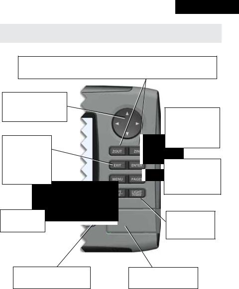
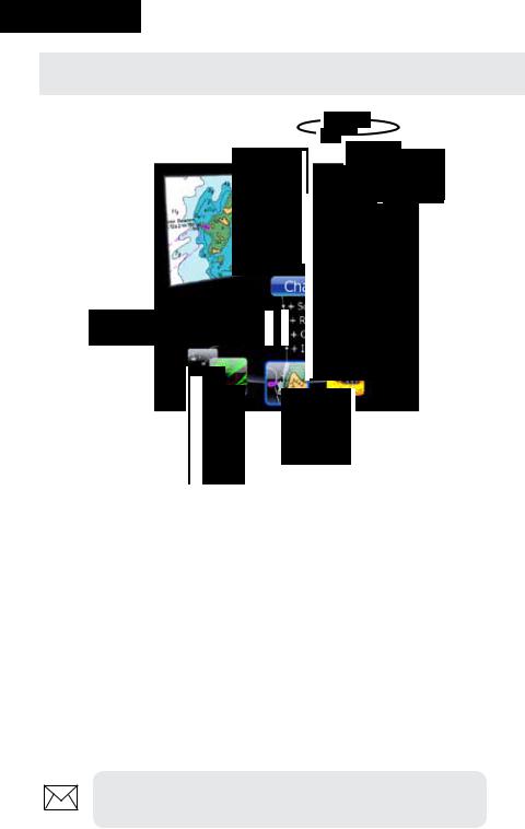
Lowrance HDS-5/7 & HDS 5m/7m
ZOUT: Zoom out to see more of the map with less detail ZIN: Zoom in to see less of the map with more detail
MOB: Pressing ZOUT and ZIN at the same time will set a man overboard waypoint
KEYPAD: move the cursor, scroll through menus, adjust features, view sonar/GPS history
EXIT: cancels entries, closes menus & windows; toggles between cursor position and chart location on Chart page
MENU: opens context & settings menus
WPT/FIND: saves a waypoint at current position; accesses searching tools
ENTER: confirms menu selections; shortcut key for functions like saving a waypoint at cursor position
PAGES: opens Pages menu; hold down the
Pages key to switch active panels when viewing combo pages
LIGHT/POWER: controls backlight level & turns the unit on/off
MMC/SD Card slot: insert
MMC/SD and high-detail mapping cards here
5
Getting Started
Getting Started
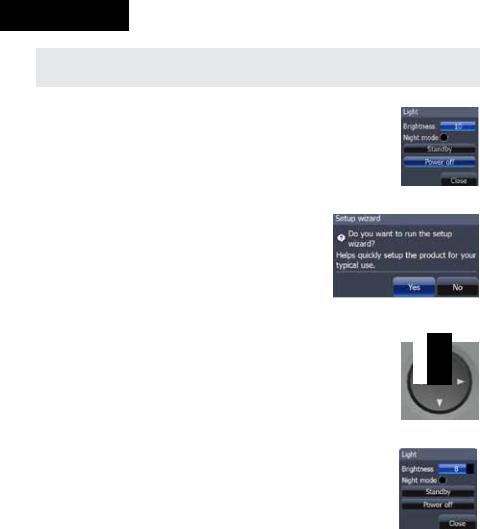
Turning on the Unit
Press the Power/Light key to turn on the unit. To turn off the unit, press the Power/Light key, select Power Off and press
Enter.
Setup wizard
The Setup wizard will appear when unit is turned on for the first time. To choose your own settings, do not run the setup wizard. To restart the Setup wizard, restore defaults.
Keypad
Keypad
This unit’s keypad can be used in two ways. Pressing the arrow symbols on the keypad will move the cursor in the corresponding direction on the screen and allow you to scroll through menus.
Backlight
Tap the Light/Powerkey to make adjustments to the backlight level and open the Backlight Menu. To turn on Night Mode from the menu, highlight Night Mode and press enter. Night mode optimizes the display for low light conditions.
Cursor
Use the unit’s keypad to move the cursor around the display, select onscreen objects, highlight data items and view sonar history. Press Exit to remove the cursor from the screen.
6
Getting Started
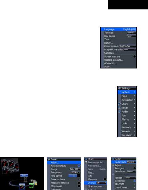
Language
Selects language used for menus, text boxes and messages.
To select a language:
1.Press Menu twice.
2.Select System and press ENTER
3.Highlight Language and press ENTER.
4.Use the keypad to select a language and press ENTER.
Menus
This unit has a Settings menu, a Pages screen and several context menus. The Settings menu provides access to the settings menus for the three main operation modes: Sonar, Chart and Radar. The Settings menu is accessed by pressing MENU twice.
The Pages screen allows you to select a page to be shown on the display. Utilities are also accessed from the Pages screen. Press the PAGES key to select a page.
Each page has its own context menu which allows you to access functions for that page. Context menus are accessible only when its corresponding page is displayed. The Sonar Menu, for example, will only be available when the Sonar Page is on the display. To access a context menu, select the desired page and press the MENU key.
Settings
menu
Pages screen |
|
|
|
|
|
Sonar menu |
|
Chart menu Radar menu |
|||
Closing Menus
Press the EXIT key to close a menu. Repeatedly pressing EXIT will close all menus, taking you back to the main screen.
7
Getting Started
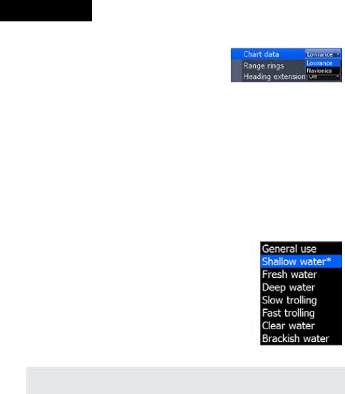
Selecting Chart Data
This unit supports Lowrance and Navionics map data. Chart data is selected from the Chart Settings menu.
To select Chart data:
1.Press Menu twice.
2.Highlight Chart and press Enter.
3.Select Chart Data and press enter.
4.Select the desired map data option and press enter.
Selecting a Fishing Mode
Fishing modes enhance the performance of your unit by providing preset packages of sonar settings geared to specific fishing conditions.
To select a fishing mode:
1.Press Menu twice.
2.Select Sonar and press enter.
3.Highlight Fishing Mode and press enter.
4.Select the desired fishing mode and press enter.
Fishing |
Depth |
Settings |
|
Palette |
Mode |
|
|||
|
|
|
|
|
General Use |
≤1,000 ft |
50% Ping speed |
Bottom brown/ blue background |
|
|
|
|
|
|
Shallow Water |
≤ 60 ft |
75% Ping speed |
bottom brown/white background |
|
|
|
|
|
|
Fresh Water |
≤ 400 ft |
50% Ping speed |
bottom brown/white background |
|
Deep Water |
≥ 1,000 ft |
50% Ping speed |
|
Deep Blue |
Slow Trolling |
≤ 400 ft |
50% Ping speed |
Bottom brown/white background |
|
|
|
|
|
|
Fast Trolling |
≤ 400 ft |
Lower chart speed |
Bottom brown/white background |
|
|
|
|
|
|
Clear Water |
≤ 400 ft |
50% Ping speed |
Bottom brown/white background |
|
Ice Fishing |
≤ 400 ft |
Settings optimized to reduce interference from |
||
|
other sonar units |
|||
|
|
|
||
8
Entering Letters in Text Boxes
This unit has some features and functions that may require you to enter data in a text box.
To enter data in a text box:
1.HighlightthetextboxandpressENTER. A keyboard will appear on the screen.
2.Use the keypad to highlight the first character and press ENTER. Repeat this step until all characters have been entered.
3.Highlight OK and press enter.
Getting Started
Keypad button controls uppercase & lowercase
Keyboard window
Restore Defaults
The Restore Defaults command switches the unit back to the settings it had when you purchased it (default).
To Restore Defaults:
1.Press Menu twice.
2.Select System and press enter.
3.Highlight Restore Defaults and press Enter.
4.Select each item you want to restore or delete and press Enter.
5.Select OK and press Enter.
9
Pages
Pages
With Chart selected, unit will display a full chart screen
Combo display options allows you to display a split screen
Page Icons
Page icons rotate around the circular
Pages menu
Chart icon rotated to center of page; has blue border indicating it is the selected page option
Pages Screen
Consists of page icons that scroll horizontally around the Pages menu. To view the pages screen, press the Pages key.
Selecting Pages
Pressing the keypad left or right will move the page icons around the menu. To select a page, move the desired page icon to the center of the screen.
When selected, the page name will be highlighted in blue at the top of a list of combo display options. Its icon, will be framed by a blue border below the list. To display the page, press ENTER.
NOTE: Hold down the Pages key to switch active panels when viewing combo pages.
10
Pages
Data Overlay
Data overlay is information you can display on top of the page screen, allowing you to customize each page with desired data.
Data Overlay menu
Every page option has its own Data Overlay menu. The menu allows you to edit, add or remove overlay data from the display. To access Data Overlay menu, select a page option and press menu.
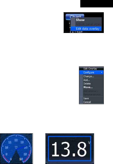
Edit Overlay menu
Accesses data overlay options for all the unit’s page screens.
To access Edit Overlay menu:
1.Select Edit data overlay from the Data overlay menu and press Enter.
2.Press menu. The Edit overlay menu will appear.
Edit Mode
When a gauge is added to the display it will be shown in edit mode. Analog and bar gauges are shaded in blue when they are in Edit Mode. Digital Gauges will be shown with a blue border.
Analog gauge in edit |
Digital gauge in edit mode |
mode |
|
11

Pages
Move or Placing a Gauge
The Move gauge command allows you to move data overlay to any position on the screen. When you use the Place gauge command, the gauge will be locked in its current position.
To move/place a gauge:
1.Press the Enter key when the gauge is in edit mode. Four directional arrows will appear.
2.Use the keypad to move the gauge into the desired location.
3.Press Enter to place the gauge.
Select Data
Used to select data that will be shown on the data overlay display. When selecting data you first will open a main data category and then choose data to be displayed from the a data subcategory.
Select data menu |
Time subcategory |
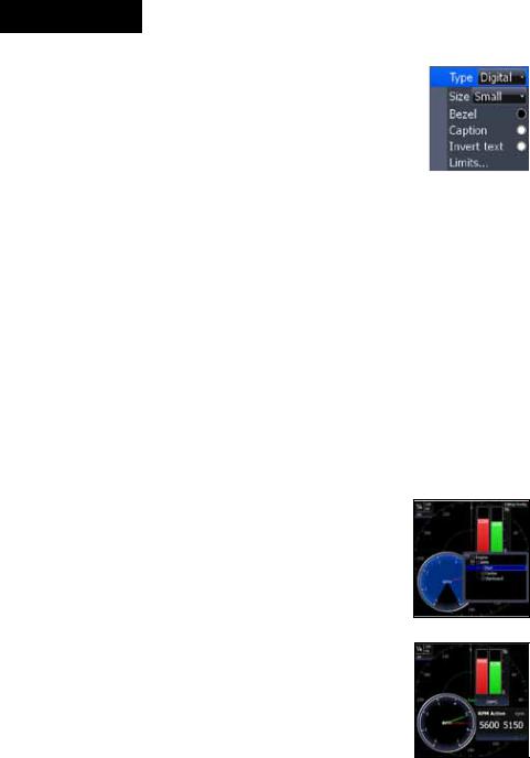
Type |
|
Switches data overlay display between analog, digital and bar gauge formats, provided the format is appropriate for the selected data type.
To change the gauge type:
1.With the gauge in edit mode, press Menu.
2.Select Configure and press Enter.
3.Select Type and press Enter.
12

Pages
 Time in digital format
Size |
|
|
|
Time in analog format |
|
|
|
||
|
|
Selects the size of the data overlay display. Data overlay can be displayed in four sizes.
With the gauge in edit mode (shaded in blue) press the Zoom out key to increase overlay size; press the Zoom in key to decrease overlay size.
|
|
|
|
|
|
|
|
|
|
|
|
|
|
|
|
|
|
|
|
Small digital gauge |
Large analog gauge |
||
Limits
Controls the number scale used on data overlay gauges and selects warning thresholds.
Changing the limits on an analog or bar gauge removes unnecessary numbers from the gauge, making them easier to read. Warnings help you stay within selected warning thresholds.
Limits are configured by inputting analog or bar gauge limits in the Limits text boxes — minimum and maximum. Warnings thresholds are entered in the Low and High text boxes.
Configuration
Limits menu
13
Pages
Configuration menu
Allows you to Add/Remove sources and adjust Bezel, Caption and Invert Text Settings. Other configuration menu options are covered previously in the section.
To access the Configuration menu, highlight Configuration on the Edit Overlay menu and press enter.
|
Configuration Settings |
|
Bezel |
Adds a bezel to the data overlay gauge, making it easier to |
|
see against certain backgrounds |
||
|
||
Caption |
Allows you to add/remove data label from gauge |
|
Invert Text |
Changes appearance of data overlay text |
Add Source
Displays the same type of data from different sources on the same analog gauge.
If, for example, you have multiple engines, you could select port engine RPM as your data type and then display starboard engine RPM using the Add source command.
Both data sources could be displayed simultaneously on an analog gauge with two needles; one dedicated to each source.
To add a source:
1.Select Add source from the Edit Overlay menu and press Enter.
2.Highlight a category and press Enter. A list of subcategories will appear.
3.Select the desired subcategory and press
Enter.
To remove add source data:
1.Highlight Remove source on the Edit overlay menu and press Enter.
2.Select the source you want to remove and press
Enter.
Add Source menu
Showing RPM from two engines.
14
Pages
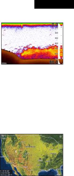
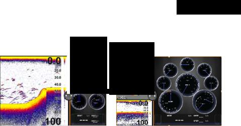
Sonar Page (Sonar units only)
Displays the water column moving from right to left on your unit’s screen. On the right side of the screen, the Amplitude Scope bar previews echoes about to appear on the display.
The sonar page supports multiple splitscreen views and 14 color palette settings. Sonar display options are covered in more detail in the Sonar Operation section.
On the Sonar Page you can:
•Move the cursor to any location on the screen to get a depth reading
•Show fish echoes as fish symbols with fish depths
•Adjust Range to view only desired portion of the water column
To access the Sonar Page, use the keypad to highlight Sonar on the Pages menu and press ENTER.
Chart Page
Consists of a Map that moves in real time as you move. By default, the map is shown from a birds-eye view with North at the top of the screen.
This page has three map orientation options (North Up, Track Up & Course Up) and two ways to view the map: 2D and Shaded Relief (only available on select models). The cursor is used to scroll the map, select
objects and find the distance between objects. The Chart page is covered in more detail in the Chart Operation section.
On the Chart Page you can:
•Save Waypoints
•Find points of interest (POI)
•Navigate routes; navigate to cursor and waypoints
To access the Chart page, use the keypad to highlight Chart on the Pages menu and press ENTER to access the Chart Page.
15
Pages
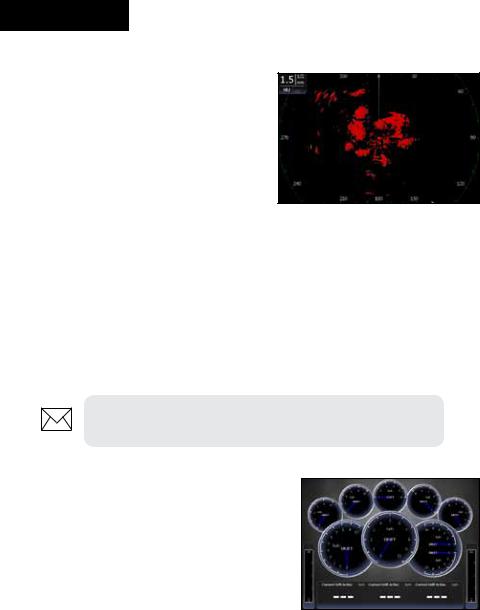
Radar Page (optional)
Displays the PPI (Position Plan Indicator) screen, Range Rings and the cursor.
The PPI can be shifted to show more of a desired portion of the screen (Look Ahead, Center & Offset) and the color palette can be changed to show returns in white, yellow, black or green. The radar page is covered in more detail in the Radar Operation section.
On the Radar Page you can:
•Overlay compass data, range rings and EBL/VRMs on display
•Choose screen orientation from Head Up, Course Up & North Up
•Make radar targets more visible via Target Expansion
Use the keypad to highlight Radar on the page screen and press ENTER to access the Radar Page.
NOTE: You will only be able to see the Radar page if your unit is connected to a radar.
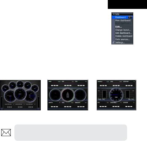
Info Page
Consists of multiple gauges — Analog, Digital and Bar — that can be customized to display selected data. Customizing the info page allows you to monitor several types of desired data at the same time.
On the Info Page you can:
•Select data to be displayed in analog gauge or digital formats
•Change the page layout using one of three templates
•Select the range (scale) of analog gauges
To access the Info Page, use the keypad to select Info on the pages screen and press enter.
16
Pages
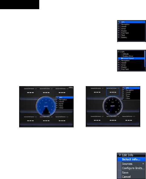
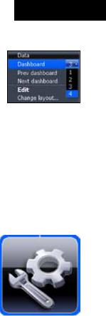
Info menu
Controls Info page data, page layout and data display format selection. To access the Data menu, press Menu while on the Info page.
Dashboards
Layout templates that are customized with selected data and saved for on-the-water viewing. You can customize a different layout template for each dashboard or add custom data to the same layout template and save it as a different dashboard each time.
Vessel layout |
Navigation Layout |
Angler Layout |
NOTE: You can toggle through the dashboard templates on the screen by pressing the keypad left/right.
Edit
Used to select information displayed on the Info page. To switch the screen to Edit Mode, select Edit from the Info menu and press enter. The active gauge will be shaded in blue (analog) or surrounded by a blue border (digital and bar).
17
Pages
To edit gauge display:
1.Use the keypad to select the gauge you want to edit and press enter. The Select Info menu will appear.
2.Use the keypad to select a data category and press enter. A list of subcategories will appear.
3.Select the desired subcategory and press enter.
4.Press Menu. The Edit Info menu will appear.
5.Select Save and press enter.
GPS category
Ground Speed
subcategory
Editing data on an analog |
Editing data on a digital gauge |
gauge |
|
Edit Info menu
Changes Info Page gauge data, allowing you to display desired data on analog, digital and bar gauges. It also controls gauge limits.
To access the Edit Info menu, switch the screen to Edit mode and press menu.
To select info:
1.Highlight Select Info from the Edit Info menu and press enter. The Select Info menu will appear.
2.Use the keypad to select the desired category and press enter. A list of subcategories will appear.
3.Select the desired subcategory and press enter.
18
Pages
To add source:
1.Select Add Source from the Edit Info menu and press enter.
2.Use the keypad to select the desired category and press enter. A list of subcategories will appear.
3.Select the desired subcategory and press enter.
To remove a source:
1.Highlight Remove Source from the Edit Info menu and press enter. The Remove data-source window will appear.
2.Select the source you want to remove and press enter.
To Configure Limits:
1.Highlight Configure Limits on the Edit Info menu and press enter. The Configure Limits menu will appear.
2.Select the desired text box and press enter.
3.Use the keypad to enter the desired limit or warning threshold.
4.Select OK and press enter.
NOTE: The Limits portion of the Configure Limits menu will only be shown when configuring analog gauge limits.
19
Pages
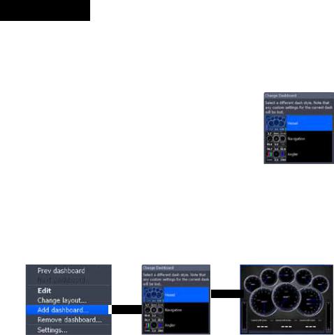
Change Layout
Controls the gauge layout of dashboard templates and customized dashboards. That allows you to select a desired gauge layout template for all dashboards.
To change layout:
1.Highlight the desired dashboard and press enter.
2.Select Change Layout from the Info menu and press enter.
3.Use the keypad to choose a gauge layout template and press enter.
Add Dashboard
Allows you to customize and save multiple dashboard templates. Desired data can be added to the gauges on each dashboard, allowing you to create custom dashboards for a variety of fishing conditions.You can even use the same gauge layout template for each dashboard.
When you have created all desired dashboards, press the keypad left/right to toggle through your dashboards.
To add a dashboard:
1.Select Add Dashboard from the Info menu and press enter. The Change Layout menu will appear.
2.Select the desired gauge layout and press enter. Refer to the previous Edit segment to customize the dashboard.
20
Pages
To remove dashboards:
1.Select the number of the dashboard you want to delete from the numerical dashboard list.
2.Highlight Remove Dashboard and press enter.
A confirmation message will appear.
3.Select Delete and press enter.
Settings
Numerical dashboard list
Opens the Settings menu. Settings information is covered in detail in the Settings menu section.
Utilities
Allows you to set alarms, view sonar logs and access other system settings.
To access Utilities:
1.Use the keypad to center the utilities icon on the screen.
2.Scroll down the list of utilities until the desired option is highlighted.
3.Press ENTER.
Utilities Icon
|
Utilities |
|
Waypoints, |
Access Waypoint, Route and Trails screen; covered in |
|
Routes/Trails |
the Chart Operation Section |
|
|
|
|
Find |
Search for POIs, Vessels, Coordinates,Trails, Waypoints |
|
and Routes; covered in Chart Operation Section |
||
|
||
Alarms |
Access alarm history, status and change settings |
|
Vessels |
View status and messages from vessels in the area |
|
Sun/Moon |
Displays time when sun and moon will rise/set |
|
Trip Calculator |
Keeps running tally/total of engine hours |
|
Files |
Access, copy and delete data files and sonar logs |
21
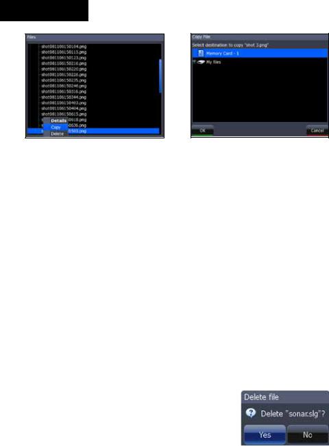
Pages
Copying a screenshot |
Copy File screen |
Data files/Sonar logs
To copy data files/sonar logs:
1.Highlight Files from the Utilities menu and press enter.
2.Select the desired File category and press the keypad to the right. A list of subcategories will appear.
3.Select a subcategory and press the keypad to the right. Highlight the desired data file/sonar log.
4.Press Menu. Highlight Copy and press enter. The Copy File screen will appear.
5.Select a place to copy the file, like an MMC card. Press enter.
To delete data files/sonar logs:
1.Highlight Files from the Utilities menu and press enter.
2.Select the desired File category and press enter. A list of subcategories will appear.
3.Select a subcategory and press enter. Highlight the desired data file/sonar log.
4.Press Menu, select Delete and press enter.
A confirmation message will appear.
5.Select Yes and press enter.
22
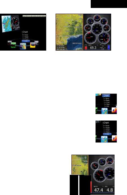
Pages
Info selected as combo |
GPS/Info combo page |
display option |
|
Displaying Combo Pages
You can display multiple pages at the same time by scrolling the desired page’s icon to the center of the screen and then choosing a secondary page from the list of combo page display options.
To display a combo page:
1.Use the keypad to select the first page for the combo display. This is the primary page, which will be displayed in the left panel.
2. Select another page from the primary page’s combo Primary page display list. This is the secondary page. It will be
displayed in the right panel.
3.Press Enter. The selected combo page will be displayed.
Selecting an Active Panel
When combo pages are displayed only one panel can be active at a time. The panel outlined with an orange border is the active panel. You will only be able to access the context menu of the active panel. Pressing the Menu key will open the active panel’s context menu.
To switch the active setting to the other panel, hold down the Pages key for 1 second.
Secondary |
page |
Chart panel is active as shown by the orange border
23
Pages
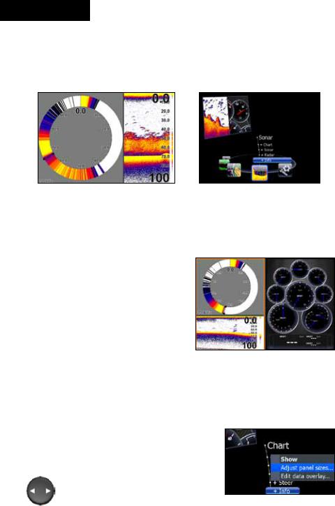
Displaying Multiple Panels (Sonar units only)
Multiple panels can be displayed by setting up a combo display using a page that supports the Split feature. By displaying multiple panels, you can view more information on the screen at one time.
Step 1: Select sonar split screen |
Step 2: Choose page from |
|
combo display options list |
To display multiple panels:
1.Select a Split view for the sonar page. (Accessing the Split feature is covered in detail in the Sonar
section.)
2.Press the Pages key and use the keypad to center the Sonar icon on the screen.
3.Use the keypad to select Info
Page from the combo page display list. Press Enter. The
combo page will be displayed with the Sonar split view on the left; the Info page on the right.
Flasher, normal sonar and the info page shown on a multi-panel display.
Adjust Panel Sizes
Controls the size of panels when combo pages or multi-panels displays are in use. Adjusting the size of the panels, allows you to emphasize the panel you want to see more clearly.
Panels can only be adjusted left/right, so the panels on the side with the split view
can not be adjusted vertically. Adjust panel sizes selected on the Data Overlay menu
24
Pages
Moving panel cursor left/right will change the size of each panel
|
|
|
|
|
|
|
|
|
|
|
|
|
|
|
|
|
|
|
|
|
|
|
|
|
|
|
|
|
|
|
|
|
|
|
|
|
|
|
|
Adjusting panels on combo page |
|
Adjusting panels on multi-panel display |
|||||
(Sonar/Info combo shown) |
|
|
(Sonar/Info combo shown) |
||||
To adjust panel sizes:
1.With the combo page or multi-panel display on the screen, press the Pages key.
2.Press menu. Highlight Adjust Panel Sizes from the Data Overlay menu and press enter.
3.Press the keypad left/right to adjust the panels to a desired size and press enter.
25
Sonar
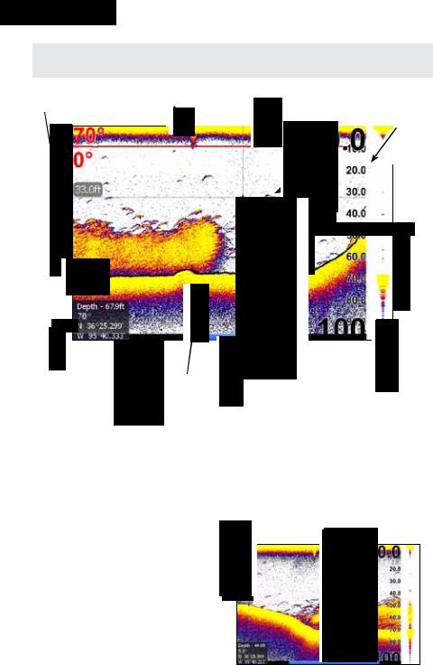
Sonar Operation (HDS-5 & 7 only)
Water column |
|
Surface clutter |
Temperature Graph |
|
Range |
|||||||||||||||||
|
|
|
|
|
|
Fish Arches |
|
|||||||||||||||
|
|
|
|
|
|
|
|
|
|
|
|
|||||||||||
|
|
|
|
|
|
|
|
|
|
|
|
|
|
|
|
|
|
scale |
||||
|
|
|
|
|
|
|
|
|
|
|
|
|
|
|
|
|
|
|
|
|
||
|
|
|
|
|
|
|
|
|
|
|
|
|
|
|
|
|
|
|
|
|
|
|
|
|
|
|
|
|
|
|
|
|
|
|
|
|
|
|
|
|
|
|
|
|
|
|
|
|
|
|
|
|
|
|
|
|
|
|
|
|
|
|
|
|
|
|
|
|
|
|
|
|
|
|
|
|
|
|
|
|
|
|
|
|
|
|
|
|
|
|
|
|
|
|
|
|
|
|
|
|
|
|
|
|
|
|
|
|
|
|
|
|
|
|
|
|
|
|
|
|
|
|
|
|
|
|
|
|
|
|
|
|
|
|
|
|
|
|
|
|
|
|
|
|
|
|
|
|
|
|
|
|
|
|
|
|
|
|
|
|
Depth
 Line
Line
Brush
Water depth, water temp and cursor coordinates
|
|
|
|
|
Cursor |
|
|
|
|
|
|
Colorline |
|
|
|||
Blue sonar history bar; reviews recent sonar history
Amplitude Scope
— shows amplitude of real-time sonar echoes
To access the Sonar Page:
1.Press the Pages key.
2.Use the keypad to select Sonar and press ENTER.
Cursor |
Blue sonar history bar |
|
Viewing Sonar History
You can review your recent sonar history by moving the cursor to the left until the screen starts to move in reverse.
To resume normal operation, move the cursor all the way to the right of the screen or press Exit.
26
Sonar
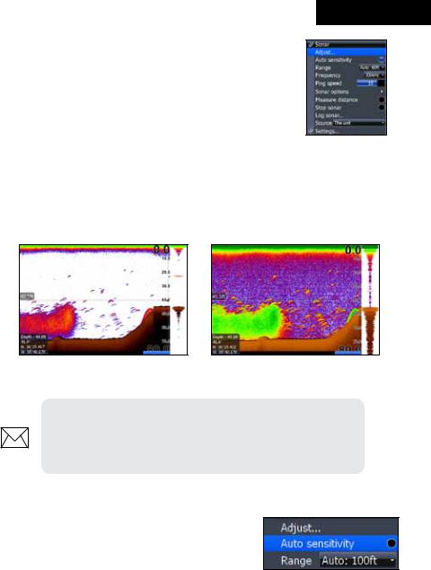
Sonar Menu
Accesses features ranging from Auto Sensitivity and Depth
Range to Frequency and Stop Sonar.
From the Sonar Page, press MENU to access the Sonar
Menu.
Sensitivity
Controls the level of detail shown on the display. Increasing Sensitivity will show more detail on the screen; decreasing Sensitivity displays less. Too much detail will clutter the screen. Conversely, desired echoes may not be displayed if Sensitivity is set too low.
Sensitivity set to 60 percent |
Sensitivity set to 80 percent |
NOTE: By default, Sensitivity is set to auto mode. You may have to turn off Auto Sensitivity to set sensitivity to a desired level. Auto Sensitivity is covered in more detail later in this section.
Auto Sensitivity
Keeps sensitivity at a level that works well under most conditions, reducing the need for adjustments. You can make minor changes to sensitivity with Auto Sensitivity turned on, but you will have to turn it off to make significant adjustments.
Auto Sensitivity can be turned on/off by selecting Auto Sensitivity from the Sonar menu and pressing ENTER.
27
Sonar
|
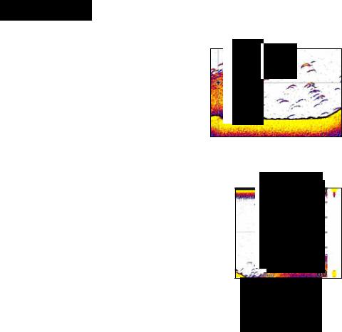
Wide yellow hard |
Reddish-blue soft |
Colorline |
sonar return |
sonar returns |
Distinguishes strong sonar echoes from weak sonar echoes. That makes it easier for you to distinguish fish or structure from the bottom.
A hard return will be shown as a wide, bright yellow line, whereas a soft return will be a narrow reddish-blue line.
Range
Used to select the section of the water column — Range set to 60 feet from surface to bottom — shown on the display.
When there is a portion of the water column you want to focus on, select a range from the Depth Range menu that includes the desired area.
The values on the Range menu determine the depth shown on the display. If you selected 20m from the
range menu the unit will display 0-20m of the water column, regardless of the water depth. There are
21 depth ranges, including automatic and custom
settings. The automatic setting will set the range from the water surface to water depth.
Frequency
This unit supports three transducer frequencies; two of which are supported by your transducer. 200 kHz has the highest sensitivity and best target discrimination in shallower water; 83 kHz offers a wider cone angle for greater water coverage and 50 kHz provides the best depth penetration. You can view both available frequencies at the same time by setting up a sonar split screen.
Split
Adjusts the configuration of sonar page display using one of four options: No Split,
Zoom, Bottom Lock and Flasher.
28
 Loading...