


HC 2062 |
Installation
Instructions
For Fully Integrated NoFrost
Combined Refrigerator-Freezers
HCB 2062
HC/HCB 20 7083 319-00
Important
PLEASE READ AND FOLLOW THESE INSTRUCTIONS
These instructions contain Warning and Caution statements. This information is important for safe and efficient installation.
Always read and follow all Warning and Caution statements!
Warning indicates a potentially hazardous situation which, if not avoided, could result in death or serious injury.
Caution indicates a potentially hazardous situation which, if not avoided, may result in minor or moderate injury.
IMPORTANT
This highlights information that is especially relevant to a problem-free installation.
Make sure incoming voltage is the same as the unit rating.
To reduce the risk of fire, electric shock, or personal injury, installation work and electrical wiring must be done by a qualified electrician in accordance with all applicable codes and standards, including fire-rated construction.
TO THE INSTALLER
It is very important that the guidelines and instructions are followed in the manual to ensure proper installation and operation of the unit. The Installation Guidelines section contains important information for making sure the installation is correct. Read and understand all the information in Installation Guidelines and in this manual before the unit is installed.
Always wear protective devices such as protective gloves and eye shields when installing the appliance. Also use
hearing protection when drilling holes into concrete floors.
Contents |
Page |
Planning Information |
|
Unit dimensions............................................... |
4 |
Unit Venting...................................................... |
4 |
Cabinet opening dimensions............................ |
5 |
Panel Dimensions - |
|
Framed Cabinet Design................................... |
6 |
Panel Dimensions - |
|
Frameless Cabinet Design.............................. |
7 |
Blocking For Safety |
|
Mounting the anti - tipping device on concrete |
|
floors................................................................ |
8 |
Mounting the anti - tipping device on wooden |
|
floors................................................................ |
8 |
Mounting the anti tipping device at cabinets |
|
deeper than 24"............................................... |
9 |
Cover strips...................................................... |
9 |
Ice Maker |
|
Safety instructions and warnings.................. |
10 |
Water connection........................................... |
10 |
Connection to the water supply..................... |
10 |
Installation |
|
Leveling the Refrigerator............................... |
12 |
Adjusting the front of the drawer................... |
12 |
Fasten the appliance in the recess................ |
12 |
Before mounting the door panels.................. |
12 |
Mounting the attachment brackets |
|
onto the door panels...................................... |
13 |
Mounting the freezer drawer panels............. |
14 |
Mounting the refrigerator door panels...... |
14-17 |
Mounting the ventilation grille........................ |
17 |
2
Installation Guidelines
Area Requirements
Verify the following:
•Floors can support refrigerator’s weight plus approximately 1200 pounds (544 kg) of food weight.
•Finished kitchen floor height is level. Appliance must be shimmed level if the floor heights
are not equal to make sure air vents are not obstructed.
•Remove anything attached to rear or side walls that can obstruct appliance opening.
•Cutout dimensions are accurate.
•Electrical outlet is in correct location.
Do not install this refrigerator-freezer next to any other refrigerator. Installing this refrigerator-freezer next to any other refrigerator or freezer can cause condensation or cause damage to the appliance.
Electrical Requirement
If codes require a separate grounding circuit to be used, have a qualified electrician install the circuit.
Do not ground to a gas pipe. Check with a qualified electrician if you are not sure
the appliance is properly grounded. Do not have a fuse in the neutral or grounding circuit.
ELECTRIC SHOCK HAZARD
•Electrically ground appliance.
•Do not use an extension cord.
•Failure to follow these instructions could result in fire or electric shock.
ELECTROCUTION HAZARD
Electrical grounding required. This appliance is equipped with a three-prong (grounding) polarized plug for your protection against possible shock hazards.
•Do not remove the round grounding prong from the plug.
•Do not use a two-prong grounding adapter.
•Do not use an extension cord to connect power to the unit.
To protect the appliance from possible damage, allow the appliance to stand 1/2 to 1 hour in place before turning the electricity on. This allows the refrigerant and system lubrication to reach equilibrium.
Customer’s Responsibility
A 115 Volt, 60 Hz, 15 Amp fused electrical supply is required. We recommend using a dedicated circuit for this appliance to prevent electrical overload. Follow the National Electrical Code and local codes and ordinances when installing the receptacle.
Blocking for Safety
The anti tipping brackets must be installed to prevent the unit from tipping after it is installed. Refer to Blocking for Safety.
Unit Venting
Do not restrict the air flow. Air flow must be provided for the unit to operate.
3
Planning Information
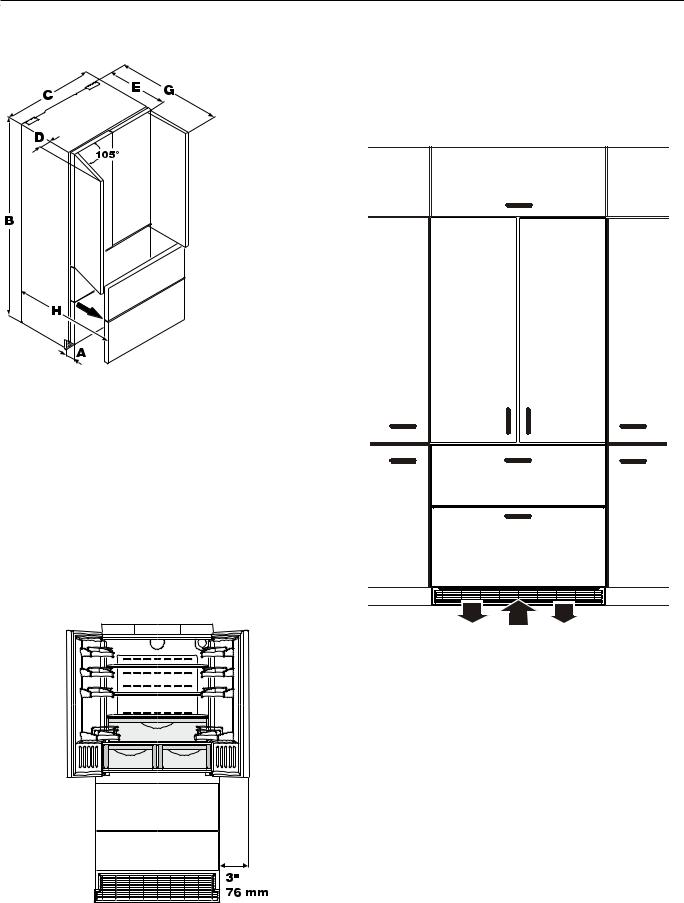
Unit Dimensions - Figure 1 |
Unit Venting - Figure 3 |
|
A = 3" (76 mm) |
|
B = 79-13/16" (2027 mm) |
Figure 1 |
C = 35-13/16" (910 mm) |
D = 3" (76 mm) |
|
|
E = 24" (610 mm) |
|
G = 42-7/16" (1078 mm) |
|
H = 37-1/8" (943 mm) |
Door swing clearence - Figure 2
Please allow for door swing clearance at locations next to a wall.
The illustrated measurement is without mounted front panels. Be sure to add your panel thickness and handle depth to this measurement in order to avoid interferences.
Figure 2
HC/HCB 20 appliances do not require any ventilation openings in the cabinet. The required airflow is directed through the toe kick area.
Figure 3
It is important to use the provided cover grille for the ventilation opening. This opening must not be covered with a cabinet base.
4
Planning Information
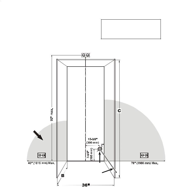
Cabinet Opening Dimensions - Figure 4
Cabinet |
Inset cabinet |
Frameless/faceframe cabinet |
Height C |
Depth B |
Depth B |
|
|
|
80" |
24" + panel thickness |
24" |
|
|
|
84" |
24" + panel thickness |
24" |
|
|
|
For appliance with panel to be flush, adjacent cabinetry depth must equal appliance depth (24") plus panel thickness (5/8" - 3/4").
IMPORTANT
Do not install the shut-off valve behind the appliance.
The position of the electrical outlet is possible within the grey shaded areas or above the appliance.
Water line opening |
Water supply line |
IMPORTANT
For 24" cabinets, the water line opening must be in the location as shown in Figure 4.
With cabinets deeper than 24", there is room to fit the pipe behind the appliance and the wall so there are no requirements for the water line lead out position.
Figure 4
IMPORTANT
The free length of the water supply line must be at least 31-1/2" (800 mm) when the tube comes out of the prescribed opening.
5
Planning Information
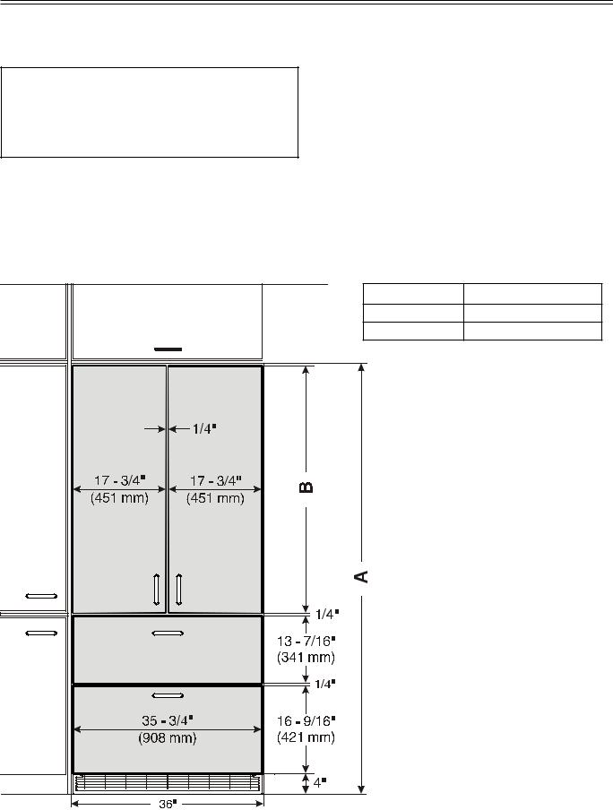
Panel Dimensions - Inset Installation Style - Figure 5
Appliance and panels sit fully within the opening and are flush with what could be its own box, between two pantry cabinets or decorative columns, etc.This is the most common installation scenario.
The panels should be at least 5/8 inch (16 mm) thick to allow the connecting rails to be fastened to them.
IMPORTANT
The maximum panel thickness is 3/4" (19 mm).
You can order stainless steel panels for inset installation style.
Refrigerator door panels 80”- article-number 9900 337-00 |
|
Refrigerator door panels 84”- article-number 9900 335-00 |
|
Freezer drawer panels - article-number 9900 323-00 |
|
Cabinet Opening A Refrigerator door panel B |
|
80" (2032 mm) |
45 - 1/4" (1150 mm) |
84" (2134 mm) |
49 - 1/4" (1251 mm) |
Figure 5 |
|
6 |
|
 Loading...