


Installation
Instructions
For Fully Integrated NoFrost
Combined Refrigerator-Freezers
HC 2082
HCB 2082
HC/HCB 2082 7084 845-00
Important
Please Read and Follow these Instructions
These instructions contain Danger, Warning and Caution notes.
This information is important for safe and efficient installation and operation.
Always read and comply with all Danger, Warning and Caution notes!
 DANGER!
Danger indicates a hazard which will cause serious injury or death if precautions are not followed.

 WARNING!
Warning indicates a potentially hazardous situation which, if not avoided, could result in death or serious injury.
 CAUTION!
Caution indicates a potentially hazardous situation which, if not avoided, may result in minor or moderate injury.
IMPORTANT
This indicates information that is especially relevant to a problem-free installation and operation.
Note to the Installer
It is very important to follow the instructions in the manual to ensure proper installation and operation of the unit.
Before installing the unit, be sure to thoroughly read and understand all of the information in this manual.
Contents |
Page |
|
Unit dimensions.............................................................. |
|
4 |
Unit Venting.................................................................... |
|
4 |
Cabinet opening dimensions......................................... |
|
5 |
Panel Dimensions - Framed Cabinet Design................ |
|
6 |
Panel Dimensions - Frameless Cabinet Design............ |
|
7 |
Mounting the anti - tipping device on concrete floors |
... 8 |
|
Mounting the anti - tipping device on wooden floors.... |
8 |
|
Mounting the anti tipping device at cabinets |
|
|
deeper than 24".............................................................. |
|
9 |
Cover strips..................................................................... |
|
9 |
Ice Maker |
|
|
Safety instructions and warnings................................. |
|
10 |
Water connection Requirements................................. |
|
10 |
Water connection Adapter............................................ |
|
10 |
Connection to the water supply................................... |
|
11 |
Leveling the Refrigerator.............................................. |
|
12 |
Adjusting the front of the drawer.................................. |
|
12 |
Fasten the appliance in the recess.............................. |
|
12 |
Before mounting the door panels................................ |
|
12 |
Mounting the attachment brackets |
|
|
onto the door panels..................................................... |
|
13 |
Mounting the freezer drawer panels............................ |
|
14 |
Mounting the refrigerator door panels..................... |
14-17 |
|
Mounting the ventilation grille...................................... |
|
17 |
R600a Refrigerant

 WARNING!
The refrigerant contained within the appliance R600a is environmentally friendly, but flammable. Leaking refrigerant can ignite.
To prevent possible ignition follow the warnings below:
• Keep ventilation openings, in
the appliance enclosure or in 
 the built-in structure, clear of
 obstruction.
• Do not damage the refrigerant circuit.
•Any repairs and work on the appliance should only be performed by the customer service department.
2
Safety
Disposal of Old Appliance
 DANGER!
Risk of child entrapment.
Child entrapment and suffocation are not problems of the past.
Junked or abandoned refrigerators are still dangerous – even if they will sit for “just a few days.”
If you are getting rid of your old refrigerator, please follow these instructions to help prevent accidents.
Before you discard old appliances:
•Take off the doors.
•Leave the shelves in place so that children may not easily climb inside.
•Cut off the power cable from the discarded refrigerator. Discard separately from the refrigerator.
•Be sure to follow your local requirements for disposal of appliances.
Contact the trash collection agency in your area for additional information.
Disposal of Carton
The packaging is designed to protect the appliance and individual components during moving and is made of recyclable materials.

 WARNING!
Keep packaging materials away from children. Polythene sheets and bags can cause suffocation!
Please recycle packaging material where facilities are available.
Electrical Safety
Connect this appliance to a 15 amp or 20 amp, 110120 VAC, circuit which is grounded and protected by a circuit breaker or fuse.
We recommend using a dedicated circuit for this appliance to prevent circuit overload and the chance of interruption to the appliance.
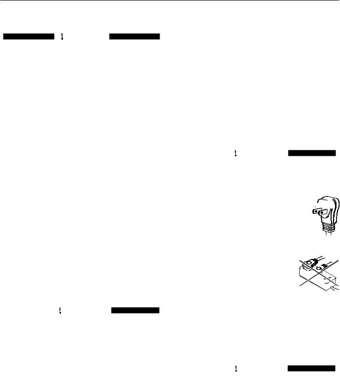
This appliance is equipped with a three-prong (grounding) polarized plug for your protection against possible shock hazards.
Where a two-prong wall receptacle is encountered, contact a qualified electrician and have it replaced with a properly grounded three-prong receptacle in accordance with all local codes and ordinances.

 WARNING!
Electrocution hazard.
Electrical grounding required.
• Do not remove the round grounding 
 prong from the plug.


• Do not use extension cords or ungrounded (two prong) adapters.
•Do not use a power cord that is frayed or damaged.
•Do not use a power strip. 

Failure to follow these instructions may result in fire, electrical shock or death.
Blocking for Safety

 WARNING!
To avoid a hazard due to instability of the appliance, it must be fixed in accordance with the instructions.
3
Planning Information
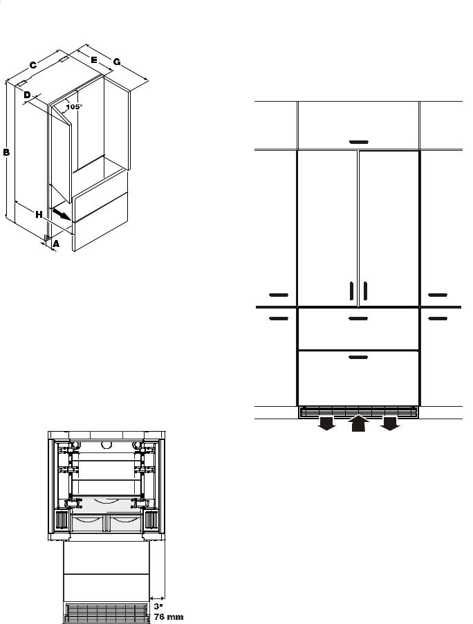
Unit Dimensions - Figure 1 |
Unit Venting - Figure 3 |
|
HC/HCB 20 appliances do not require any ventilation |
|
openings in the cabinet. The required airflow is directed |
|
through the toe kick area. |
|
A = 3" (76 mm) |
|
B = 79-13/16" (2027 mm) |
Figure 1 |
C = 35-13/16" (910 mm) |
D = 3" (76 mm) |
|
|
E = 24" (610 mm) |
|
G = 42-7/16" (1078 mm) |
|
H = 37-1/8" (943 mm) |
Door swing clearence - Figure 2
Please allow for door swing clearance at locations next to a wall.
The illustrated measurement is without mounted front panels. Be sure to add your panel thickness and handle depth to this measurement in order to avoid interferences.
Figure 2
Figure 3
It is important to use the provided cover grille for the ventilation opening. This opening must not be covered with a cabinet base.
4
Planning Information
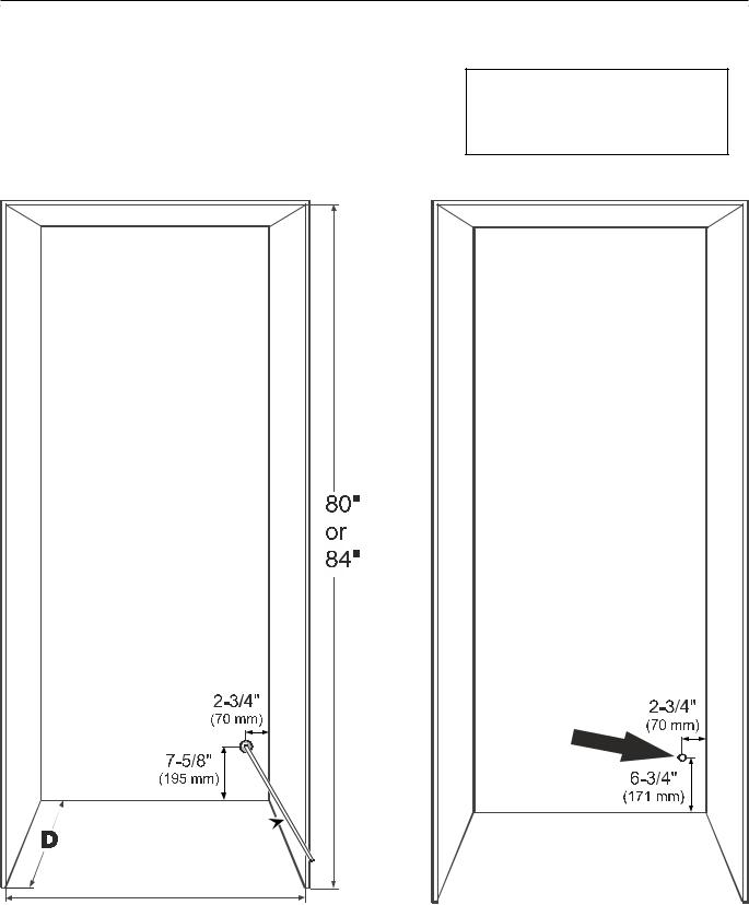
Cabinet Opening Dimensions - Figure 4
Inset cabinet |
Frameless/faceframe cabinet |
Depth D |
Depth D |
|
|
24" + panel thickness |
24" |
|
|
IMPORTANT
For 24" cabinets, the water line opening must be in the location as shown.
With cabinets deeper than 24", there is room to fit the pipe behind the appliance and the wall so there are no requirements for the water line lead out position.
The free length of the water supply line must be at least 31-1/2" (800 mm) when the tube comes out of the prescribed opening.
Do not install the shut-off valve behind the appliance.
Water supply line 
36" Single 72" Side by Side
Figure 4
For appliance with panel to be flush, adjacent cabinetry depth must equal appliance depth (24") plus panel thickness (5/8" - 3/4").
This is where the power cord extends from the back of the appliance.
Free length of the power cord = 90 inch (2280 mm)
Be sure to take these specifications into consideration when choosing the location of the electrical outlet.
IMPORTANT
The electrical outlet must not be situated behind the appliance and must be easily accessible.
5
Planning Information
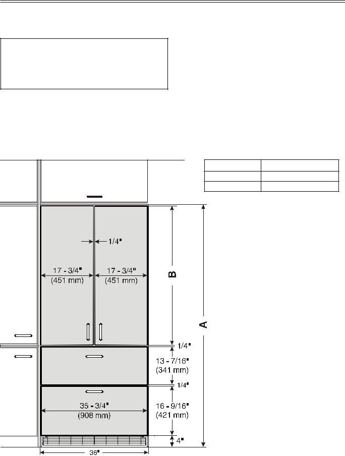
Panel Dimensions - Inset Installation Style - Figure 5
Appliance and panels sit fully within the opening and are flush with what could be its own box, between two pantry cabinets or decorative columns, etc. This is the most common installation scenario.
The panels should be at least 5/8 inch (16 mm) thick to allow the connecting rails to be fastened to them.
IMPORTANT
The maximum panel thickness is 3/4" (19 mm).
You can order stainless steel panels for inset installation style.
Refrigerator door panels 80”- article-number 9900 337-00 |
|
Refrigerator door panels 84”- article-number 9900 335-00 |
|
Freezer drawer panels - article-number 9900 323-00 |
|
Cabinet Opening A Refrigerator door panel B |
|
80" (2032 mm) |
45 - 1/4" (1150 mm) |
84" (2134 mm) |
49 - 1/4" (1251 mm) |
Figure 5 |
|
6 |
|
 Loading...