


Detachable Front
Panel Car Receiver
OWNER’S MANUAL
MODEL:TCC-2510/2515
Take time to read this OWNER’S MANUAL thoroughly. Familiarity with installation and operating procedures will help you obtain the best performance from your CAR Receiver.
P/N:3828SNC064B
Installations

 Precautions:
 Be careful not to touch the rear side panel of the unit when removing the unit from the installation sleeve, since it may be hot. On this side the cooling ribs are located.
 The unit is designed to operate only on 12 volt DC negative ground electrical system.
 When you replace the fuse, be sure to use a fuse of specified amperage for each wire as mentioned in chapter “Connections”. Using a fuse of higher amperage may cause serious damage to the unit.
Notes:
 Use only the parts included with the unit to ensure
installation. The use of unauthorized arts can cause malfunctions.
 Consult with your nearest car audio dealer if installation requires the drilling of holes or other modifications of the vehicle.
 Do not use the front panel as a way of gripping the unit during installation and wiring. The front panel may come away and the unit may drop on the floor.

 Mounting the unit
Dashboard
Installation sleeve
Bend the claws according to the thickness
of the dashboard.

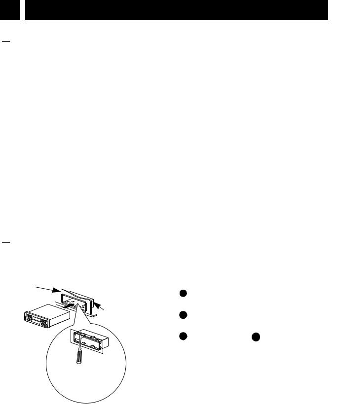
 When removing the unit from the installation sleeve
If you need to remove the unit from the installation sleeve, proceed as follows.
1Remove the rear supporter from the unit.
2Remove the front panel from the unit.
|
A into hole on one |
side of the |
and pull the lever |
toward you. Do |
same |
operation on |
other side and |
pull out the |
from the |
installation sleeve.
2

Installations
1 |
2 |
A
A
Connections
 Main connector
Connect the main connector to the female connector on the back of the unit.

 Antenna Connection
Insert the plug of the car antenna cable into the jack at the rear of the unit.

 Memory Back-up Lead
(Yellow)
Connect the yellow memory power supply wire to a 12V + terminal that is always supplied with power regardless of the vehicle’s ignition switch position. If this connection is made incorrectly or is not made at all, the unit will not work.

 Ground Connection(Black)
 Connect the ground lead (black) to a metal part of the vehicle and secure it using the screw provided on the vehicle for this purpose.
 If this connection is loose, or if the cord is connected to something other than a metal part of the car, noise or malfunction may result.

 Power Supply Lead
(Red)
Connect the red power supply wire to the 12V + terminal controlled by the car ignition switch.

 Line Out Jacks(Optional)
Connect to the Line-in RCA jacks of the power amplifier.

 Power Antenna
Lead/External Amplifier
Remote Turn-on Lead
Your will find a separate lead, blue with a male terminal suitable to many automatic antenna. This lead is not to be used with nonautomatic antenna. If an automatic car antenna is used, when connecting the lead, the antenna will be automatically extened when the main switch is turned on. This can also be used as a remote turnon wire connection for amplifiers that have a remote sensing lead. Using this connection will allow simultaneous turning on/off of the radio and an external amplifier.
3
 Loading...