


LGEPR_MCV902_MCD502_ENG_MFL32702807
MINI Hi-Fi SYSTEM
OWNER’S MANUAL
MODEL: MCV902
MCV902-A0U/D0U/X0U,
MCS902F, MCS902S,
MCS902AW, MCS902W
MCD502
MCD502-A0U/D0U/X0U,
MCS502F
Before connecting, operating or adjusting this product, please read this instruction booklet carefully and completely.
USB 

Safety Precaution
CAUTION
RISK OF ELECTRIC SHOCK
DO NOT OPEN
CAUTION: TO REDUCE THE RISK
OF ELECTRIC SHOCK
DO NOT REMOVE COVER (OR BACK) NO USER-SERVICEABLE PARTS INSIDE REFER SERVICING TO QUALIFIED SERVICE PERSONNEL.
This lightning flash with arrowhead symbol within an equilateral triangle is intended to alert the user to the presence of uninsulated dangerous voltage within the product’s enclosure that may be of sufficient magnitude to constitute a risk of electric shock to persons.
The exclamation point within an equilateral triangle is intended to alert the user to the presence of important operating and maintenance (servicing) instructions in the literature accompanying the product.
WARNING: TO PREVENT FIRE OR ELECTRIC SHOCK HAZARD, DO NOT EXPOSE THIS PRODUCT TO RAIN OR MOISTURE.
WARNING: Do not install this equipment in a confined space such as a book case or similar unit.
CAUTION: Do not block any ventilation openings. Install in accordance with the manufacturer's instructions.
Slots and openings in the cabinet are provided for ventilation and to ensure reliable operation of the product and to protect it from over heating.
The openings should be never be blocked by placing the product on a bed, sofa, rug or other similar surface. This product should not be placed in a built-in installation such as a bookcase or rack unless proper ventilation is provided or the manufacturer's instruction has been adhered to.
CAUTION:
This product employs a Laser System.
To ensure proper use of this product, please read this owner’s manual carefully and retain it for future reference. Should the unit require maintenance, contact an authorized service center.
Use of controls, adjustments or the performance of procedures other than those specified herein may result in hazardous radiation exposure.
To prevent direct exposure to laser beam, do not try to open the enclosure. Visible laser radiation when open. DO NOT STARE INTO BEAM.
CAUTION: The apparatus should not be exposed to water (dripping or splashing) and no objects filled with liquids, such as vases, should be placed on the apparatus.
CAUTION concerning the Power Cord
Most appliances recommend they be placed upon a dedicated circuit;
That is, a single outlet circuit which powers only that appliance and has no additional outlets or branch circuits. Check the specification page of this owner's manual to be certain.
Do not overload wall outlets. Overloaded wall outlets, loose or damaged wall outlets, extension cords, frayed power cords, or damaged or cracked wire insulation are dangerous. Any of these conditions could result in electric shock or fire. Periodically examine the cord of your appliance, and if its appearance indicates damage or deterioration, unplug it, discontinue use of the appliance, and have the cord replaced with an exact replacement part by an authorized servicer.
Protect the power cord from physical or mechanical abuse, such as being twisted, kinked, pinched, closed in a door, or walked upon. Pay particular attention to plugs, wall outlets, and the point where the cord exits the appliance.
To disconnect power from the mains, pull out the mains cord plug. When installing the product, ensure that the plug is easily accessible.
POWER SAVE MODE - OPTIONAL
You can set up the unit into an economic power save mode.
In the power-on status, press and hold  / ] (POWER) button for about 3 seconds.
-Nothing is displayed in the display window when the unit goes into the power save mode.
To cancel power save mode, press  / ] (POWER).
2
Before use
Contents
Before use
About the Symbols for instruction /
Notes on Discs / Notes on Tapes . . . . . . . .3
Front / Back Panel . . . . . . . . . . . . . . . . . .4
Remote Control . . . . . . . . . . . . . . . . . . . . .5
Connections |
|
Speaker System Connections . . . . . . . . . |
6 |
Antenna (Aerial) Connections / |
|
Auxiliary Equipment Connections / |
|
Optional Equipment Connections . . . . . . . |
7 |
Operation |
|
Audio Adjustment . . . . . . . . . . . . . . . . . .8-9 Sleep Timer Function / Setting the Clock . .9 Timer Function . . . . . . . . . . . . . . . . . . . .10 Presetting the Radio Stations /
Listening to the Radio . . . . . . . . . . . . . . .11
RDS Function - OPTIONAL . . . . . . . . . . .12 Tape Playback / Tape Recording . . . . . . .13
CD Playback . . . . . . . . . . . . . . . . . . . . . .14 To Program Play / Repeat /
To check MP3 file information . . . . . . . . .15
About MP3/WMA . . . . . . . . . . . . . . . . . .16 USB Function . . . . . . . . . . . . . . . . . . . . . . .17
Reference
Troubleshooting . . . . . . . . . . . . . . . . . . .18
Specifications . . . . . . . . . . . . . . . . . . . . .19
About the symbols for instruction
Indicates hazards likely to cause harm to the unit itself or other material damage.
Note Indicatesfeatures. special notes and operating
Notes on Discs
Handling discs
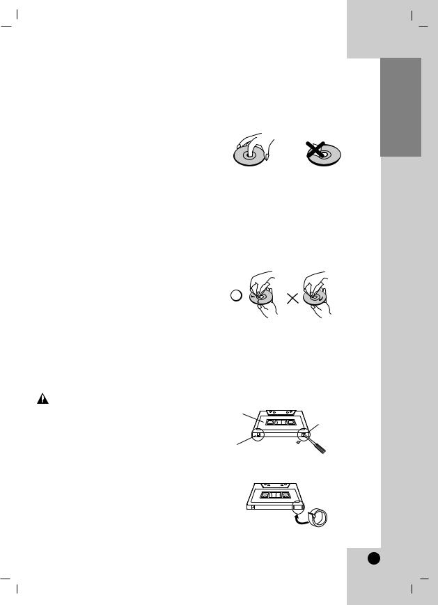
Do not touch the playback side of the disc. Hold the disc by the edges so that fingerprints do not get on the surface. Never stick paper or tape on the disc.
Storing discs
After playing, store the disc in its case. Do not expose the disc to direct sunlight or sources of heat and never leave it in a parked car exposed to direct sunlight.
Cleaning discs
Fingerprints and dust on the disc can cause poor picture quality and sound distortion. Before playing, clean the disc with a clean cloth. Wipe the disc from the center outward.
Do not use strong solvents such as alcohol, benzine, thinner, commercially available cleaners, or anti-static spray intended for older vinyl records.
Notes on Tapes
Preventing record
Removing the tab(s) of the cassette (with a small screwdriver) will prevent accidental erasure.
Side A
Tab for side A
Tab for side B
To record again, cover the hole of the tab with an adhesive tape.
Adhesive tape
<![endif]>Before use
3

Front / Back Panel |
|
|
||
|
|
|
MCV902 Model |
|
1 |
|
9 |
|
|
2 |
|
|
|
|
|
|
|
|
|
3 |
|
10 |
|
|
4 |
|
|
|
|
5 |
|
|
|
16 |
|
|
|
|
|
6 |
|
11 |
|
17 |
7 |
|
12 |
|
18 |
|
|
|
|
19 |
8 |
|
|
13 |
20 |
|
|
|
14 |
|
1. • DISC SKIP button |
|
|
||
|
• CD SELECT buttons (DISC1, DISC2, DISC3) |
MCD502 Model |
||
|
• Z OPEN/CLOSE button |
|||
|
|
|
||
2. |
DISPLAY WINDOW |
|
|
|
3. |
|
/ ] (POWER) button |
|
|
4. |
• XDSS button |
15 |
|
|
|
• AUTO TUNING DOWN/UP button |
|
|
|
|
|
REWIND/ FAST FORWARD (bb/BB) |
|
|
|
|
button |
7. |
Z PUSH EJECT position - TAPE 1 |
|
• PRESET DOWN/UP button |
|||
|
|
BACKWARD PLAY (b) button : OPTIONAL |
8. |
• GAME LINK connector |
|
|
FORWARD PLAY (B) button |
|
(VIDEO IN, AUDIO L/R) |
|
• STOP (x)/ CLEAR button |
9. |
• USB connector |
|
|
• OAO button |
CD DOOR |
||
5. • FUNCTION SELECT buttons |
10. |
• CLOCK button |
||
|
|
[ TUNER, TAPE, CD, AUX / AV, USB ] |
|
• TIMER button |
|
• PLAY MODE (DEMO) button |
|
• ST./ MONO/ NOR. DUBB. button |
|
|
• PROG. MEMO. button |
|
• CD SYNC./ HI-DUBB. button |
|
|
• RECz/ PAUSE[] (RECORD/ RECORD |
11. |
• MIC1/ MIC2 (MIC JACK) |
|
|
|
PAUSE) button |
|
: 6.3 mm - OPTIONAL |
|
• SET/ RDS(OPTIONAL)/ CD[]/ AM-NOISE |
|
• MIC VOL. (MIC VOLUME KNOB) |
|
|
|
button |
|
- OPTIONAL |
|
• VOLUME CONTROL KNOB |
12. |
Z PUSH EJECT position - TAPE 2 |
|
|
• EQ button |
13. |
SPEAKER TERMINAL (MCV902 model) |
|
|
• SURROUND button |
14. |
POWER CORD |
|
|
• USER EQ button |
15. |
SPEAKER TERMINAL (MCD502 model) |
|
|
• MP3 OPT (MP3 OPTIMIZER) button |
16. |
AM/ FM ANTENNA TERMINAL |
|
|
• MULTI JOG |
17. |
AUX IN (AUXILIARY INPUT connector) |
|
|
|
MANUAL TUNING |
18. |
VIDEO OUT connector |
|
|
CD SKIP (./>) |
19. |
WOOFER SYSTEM connector |
|
|
CLOCK ADJUST |
|
(MCV902 model) |
6. |
|
PHONES (HEADPHONE JACK) |
20. |
SUB WOOFER SPEAKER TERMINAL |
|
: |
6.3mm |
|
(MCV902 model) |
4

Remote Control
|
LINK button (MCV902 model) |
|
WOOFER POWER button |
|
|
(MCV902 model) |
MUTE button |
|
POWER button |
|
|
|
• USB button |
|
PRESET/FOLDER( / ) buttons |
• FUNCTION button |
|
VOLUME ( / ) buttons |
||
|
||
SLEEP button |
|
|
|
DIMMER button |
|
CD FUNCTION buttons |
|
|
PLAY/PAUSE (B/[]) button • |
PROGRAM/MEMO button |
|
CD STOP(x) button • |
||
|
||
CD SKIP/SEARCH • |
TAPE FUNCTION buttons |
|
(. bb/BB >) buttons |
||
• BACKWARD PLAY (b) button |
||
TUN.(-/+) buttons • |
||
: OPTIONAL |
||
REPEAT button • |
||
• FORWARD PLAY (B) button |
||
|
||
D.SKIP button |
• FAST REWIND PLAY (bb) button |
|
• FAST FORWARD PLAY (BB) button |
||
|
||
EQ PATT. • |
• TAPE-1/2 SELECT buttons |
|
• RECORD/ RECORD PAUSE (z/[]) |
||
(EQUALIZER PATTERN) button |
||
XDSS button • |
button |
|
• TAPE STOP (x) button |
||
SURR. (SURROUND) button • |
||
OAO button • |
RANDOM button |
|
|
||
NUMERIC buttons |
INFO (MP3/ WMA file information |
|
display) button |
||
|
Remote Control battery installation
Detach the battery cover on the rear of the remote control, and insert two R03 (size AAA)
| <![if ! IE]> <![endif]>AAA |
<![if ! IE]> <![endif]>AAA |
batteries with |
and |
|
|
aligned correctly. |
|
 Caution
:Do not mix old and new batteries. Never mix different types of batteries (standard,
alkaline, etc.).
Remote Control Operation Range
Point the remote control at the remote sensor and press the buttons.
• Distance : About 23 ft (7 m) from the front of the remote sensor.
• Angle : About 30° in each direction of the front of the remote sensor.
<![endif]>Before use
5

Connections |
|
|
|
Speaker System Connections |
|
|
|
MCV902 Model |
|
|
|
|
|
subwoofer(A) |
subwoofer(B) |
Surround |
Surround |
|
|
speaker |
speaker |
|
|
(Left) |
(Right) |
|
|
Wire band color: Blue |
Gray |
Orange |
|
Front |
Front |
Notes: |
|
speaker |
speaker |
|
|
• Do not place the surround/ subwoofer |
|||
(Left) |
(Right) |
speakers by TV. |
|
|
|
|
|
|
|
• If TV screen becomes discolored do not |
|
White |
Red |
place front speakers within 30cm from TV. |
|
|
|
||
Connection of the front speakers
Connect the speaker cables to the front speaker terminals.
Connection of the surround speakers
Connect the speaker cables to the surround speaker terminals.
Connection of the subwoofer
Connect the subwoofer(A) cables to the subwoofer terminals and the woofer system cable to the woofer system connector. Connect the subwoofer(B) speaker cables to the subwoofer(A) speaker terminals.
MCD502 Model
Front speaker |
Front speaker |
(Right) |
(Left) |
Red |
White |
Connection of the front speakers
Connect the front speaker cables to the speaker terminals.
Notes:
•Connect the speakers using the supplied speaker cables by matching the colors of the terminals and those of the cords.
•Be sure to match the speaker cord to the appropriate terminal on the components: + to + and – to –. If the cords are reversed, the sound will be distorted and will lack base.
•If you use front speakers with low maximum input rating, adjust the volume carefully to avoid excessive output on the speaker.
•Connect the Left/Right speaker correctly. If it reversed, the sound may be distorted.
6
 Loading...