


LS-T186ABL

SERVICE MANUAL
Room Air Conditioner
CAUTION
-BEFORE SERVICING THE UNIT, READ THE SAFETY
PRECAUTIONS IN THIS MANUAL.
-ONLY FOR AUTHORIZED SERVICE PERSONNEL.
MODEL :
LS-T186ABL/ABG/CBG/CEL/EEL/CDL/ADL/ADG
LS-T186AHG/FBG/CBL/AEL/NEG/AEM/ABM
LS-T246ABL/CBG/CEL/EEL/QEG/SEG/CEM
LS-T266CBG/FBG/ABL/CEL
LS-T246LEL/LEM/ABM/AAL
WEBSITE http://biz.LGservice.com
E-MAIL http://www.LGEservice.com/techsup.html

Contents
Details of 2002 LG Model Name............................................................................................ 3
Functions................................................................................................................................4
Product References .............................................................................................................. 7
Dimensions............................................................................................................................. 8
Refrigeration Cycle Diagram............................................................................................... 10
Wiring Diagram..................................................................................................................... 11
Operation Details ................................................................................................................. 12
Display Function .................................................................................................................. 19
Self-diagnosis Function....................................................................................................... 19
Installation ............................................................................................................................ 20
Operation .............................................................................................................................. 31
Disassembly of the parts (Indoor Unit).............................................................................. 33
2-way, 3-way Valve................................................................................................................ 36
Cycle Troubleshooting Guide.............................................................................................. 43
Electronic Parts Troubleshooting Guide............................................................................ 44
Electronic Control Device.................................................................................................... 52
Schematic Diagram.............................................................................................................. 54
Exploded View and Replacement Parts List...................................................................... 57
-2-

Details of 2002 LG Model Name
-3-
12
3456789
Code Type Code of Model Meaning
1,2 Type of Airconditioner A~Z LS: LG Split Type Airconditioner
3 Chassis A~Z Name of toll of Unit
Ex. LS-R ➔ S R Chassis
4,5 Capacity(Btu/h) 1~9 Cooling/Heating Capacity
Ex. "09" ➔ 9,000Btu/h
6 Electric Range 1~9 Electric Standard
1 ➔ 115V/60Hz 6 ➔ 220~240V/50Hz
2 ➔ 220V/60Hz 7 ➔ 110V, 50/60Hz
3 ➔ 208~230V/60Hz 8 ➔ 380~415V/50Hz
5 ➔ 200~220V/50Hz 9 ➔ 380~415V/60Hz
7 Serial No. 0~9
A~Z
8 Cooling/Heating A~Z
9 LG/OEM Brand A~Z L: LG Brand M: 1st OEM Brand
G: 2nd LG Brand N: 2nd OEM Brand
-
Basic A 0
Plasma Filter B 1
Auto Swing
+ Plasma Filter C 2
Telephone + LED Display D 3
Telephone + LCD Display E 4
Auto Swing
+ Plasma Filter + Telephone + LCD
F5
Low Ambient + Ambient/change G 6
Plasma Filter + Low Ambient + Ambient/change
H7
Internet J 8
Auto Swing + Plasma Filter + Oxygen Generator
K9
Auto Swing + Soft Start L Z
Auto Swing + Star Rating M Y
Auto Swing + Star Rating + Plasma Filter N X
Auto Swing + Soft Start + Star Rating P W
Auto Swing + Soft Start + Star Rating 4 + Plasma
QV
Auto Swing + Telephone + LCD R U
Auto Swing + Telephone + LCD + Soft Start
ST
C/O
C
A
D
G
K
H/P
H
B
E
J
L
E/H+C/O
X
5
7
-
-
E/H+H/P
Y
6
8
-
-
C/O
F
M
Q
-
-
H/P
R
P
S
-
-
C/O
V
W
1
3
H/P
N
Y
2
4
H/PTH/P
U
INDOOR
BASIC
BASIC
PLASMA
PLASMA
GOLD FIN
OUTDOOR
BASIC
GOLD FIN
GOLD FIN
BASIC
GOLD FIN
UNIT
R22
HFC R22+AC INV.
HFC+AC
INV.
HFC+DC
INV.
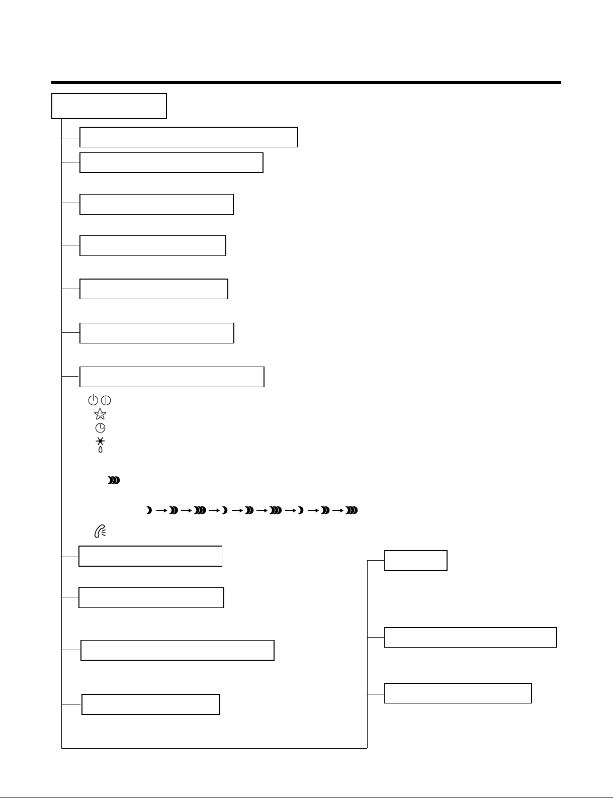
Functions
• Room temperature sensor. (THERMISTOR)
• Maintains the room temperature in accordance with the Setting Temp.
• Indoor fan is delayed for 5 sec at the starting.
• Restarting is inhibited for approx. 3 minutes.
• High, Med, Low, CHAOS, JET COOL
---
Lights up in operation
---
Lights up in Sleep Mode
---
Lights up in Timer Mode
---
Lights up in Defrost Mode (for Heating Model)
OUTDOOR---
Lights up in compressor operation (for Cooling Model)
---
The function illustrates its dynamic mode
by using a multiple lighting system.
()
---
Linghts up in Telephone Control operation.
• Intermittent operation of fan at low speed.
• The fan is switched to low(Cooling), med(Heating) speed.
• The unit will be stopped after 1, 2, 3, 4, 5, 6, 7 hours.
• The fan is switched to intermittent or irregular operation
•
The fan speed is automatically switched from high to low speed.
• The louver can be set at the desired position or swing
up and down automatically.
Indoor Unit
Operation ON/OFF by Remote controller
Sensing the Room Temperature
Room temperature control
Starting Current Control
Time Delay Safety Control
Indoor Fan Speed Control
Operation indication Lamps (LED)
Soft Dry Operation Mode
• The function will be operated while in any
operation mode with selecting the function.
• The function is to be stopped while it is
operating with selecting the function.
• Both the indoor and outdoor fan stops during defrosting.
• The indoor fan stops until the
evaporator pipe temperature will be reached
at 28°C.
Sleep Mode Auto Control
Natural Air Control by CHAOS Logic
Airflow Direction Control
PLASMA
-4-
Defrost(Deice) control (Heating)
Hot-start Control (Heating)
PLASMA
-5-
Healthy Dehumidification Operation Mode.
( )
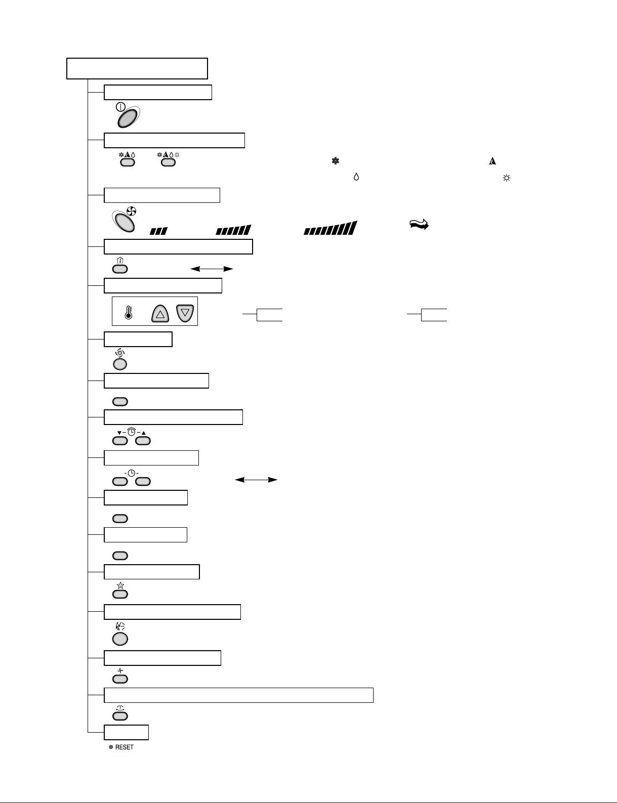
Remote Control
Operation ON/OFF
Reset
Operation Mode Selection
Temperature Setting
Timer Selection
Timer Setting
JET COOL
Timer Cancel
Sleep Operation
Airflow Direction Control
(Cooling
model only)
(Heating
model only)
TEMPERATURE
LOW HIGH
Cooling Operation Mode.( )
Heating Operation Mode.( )
Auto Operation Mode.( )
Fan Operation Mode
Horizontal Airflow Direction Control Button(Optional)
Room, Temperature Display
Setting the Time or Timer
PLASMA(Optional)
ON OFF
SET
PLASMA
CANCEL
Fan Speed Selection
(Low) (Med) (High) (CHAOS)
: (High:39°C Low:11°C)
: OFF, ON, OFF ON
: Cancel Sleep Mode, Timer ON or Timer OFF
: 1, 2, 3, 4, 5, 6, 7, Off Timer
: Fan Operates without cooling or heating.
Cooling
Down to 18°C
Up to 30°C
Heating
Down to 16°C
Up to 30°C
-6-
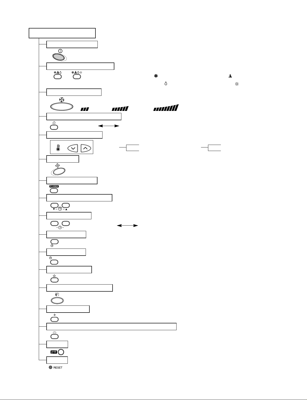
Healthy Dehumidification Operation Mode.
( )
Remote Control
Operation ON/OFF
Reset
Operation Mode Selection
Temperature Setting
Timer Selection
Timer Setting
JET COOL
Timer Cancel
Sleep Operation
Airflow Direction Control
(Cooling
model only)
(Heating
model only)
TEMPERATURE
LOW HIGH
Cooling Operation Mode.( )
Heating Operation Mode.( )
Auto Operation Mode.( )
Air Circulation
Horizontal Airflow Direction Control Button(Optional)
Room, Temperature Checking
Setting the Time or Timer
PLASMA(Optional)
Fan Speed Selection
(Low) (Med) (High)
ON
OFF
CANCEL
SET
2nd F
: (High:39°CLow:11°C)
: OFF, ON, OFF ON
: Cancel Sleep Mode, Timer ON or Timer OFF
: 1, 2, 3, 4, 5, 6, 7, Off Timer
: Fan Operates without cooling or heating.
Cooling
Down to 18°C
Up to 30°C
Heating
Down to 16°C
Up to 30°C
-7-
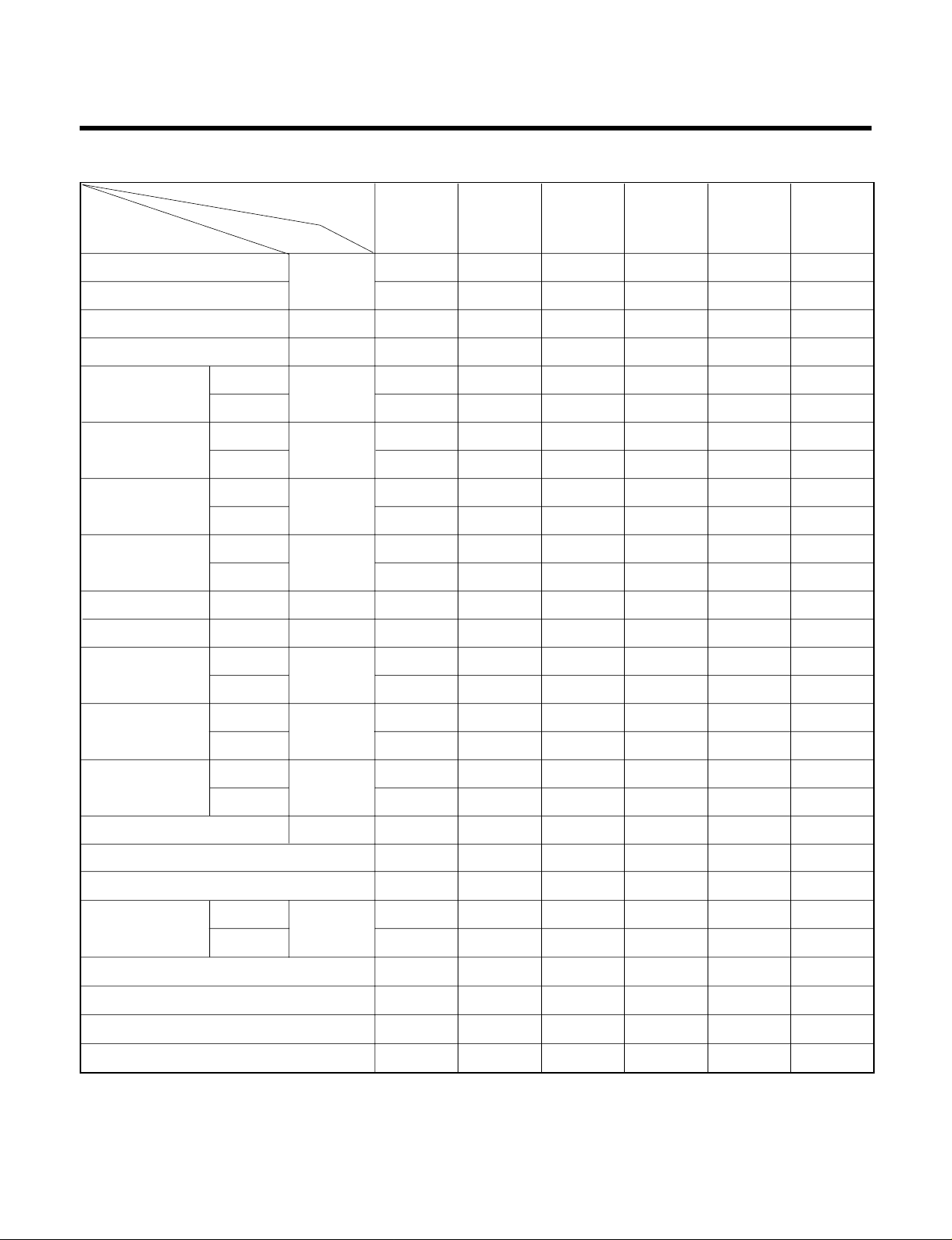
Product References
Model Name
Item Unit
Cooling Capacity
Btu/h
Heating Capacity
Moisture Removal l/h
Power Source Ø, V, Hz
Cooling
W
Heating
Running Cooling
A
Current Heating
E.E.R. Cooling Btu/hW
C.O.P Heating
Refrigerant g
Airflow Direction Control (Up & Down)
Remocon Type
inch(mm)
Sleeping Operation
Drain Hose
Connecting Cable
Power Cord
Air Circulation
Noise Level
Input
m3/min
dB (A)±3
Indoor
Outdoor
Indoor
Outdoor
Indoor
Outdoor
Indoor
Outdoor
Indoor
Outdoor
Liquid
Gas
Service Valve
Motor Output
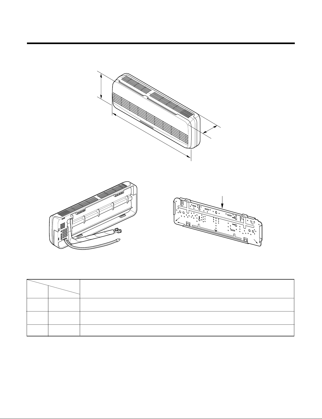
Dimensions
(W x H x D)
Net. Weight
W
mm
kg
NOTE: Please refer to Label Quality on the product since this specification may be changed for improving
performance
LS-T186_Series
LS-T186CDL
LS-T186ADG
LS-T186NEG
LS-T246_Series
LS-T266_Series
LS-T246QEG LS-T246AAL
18,000 18,500 17,500 24,000 24,000 24,000
19,000 - 18,000 24,000 24,000 -
2.2 2.2 2.2 2.88 2.88 2.88
1Ø, 220-240V, 50Hz 1Ø, 220-240V, 50Hz 1Ø, 220-240V, 50Hz 1Ø, 220-240V, 50Hz 1Ø, 220-240V, 50Hz 1Ø, 220-240V, 50Hz
13.4 13.4 13.4 14.9 14.9 14.9
42 42 42 42 14.9 14.9
42 42 42 47 47 47
55 55 55 57 58 58
1,860 1,610 1,590 2,700 2,300 2,700
1,870 - 1,630 2,650 2,300 -
9.2 9.2 7 12.6 10.5 12.6
9.2 - 7 12.2 10.5 -
9.6 9.6 11 8.88 10.4 9.0
2.98 - 3.23 2.69 3.06 22 22 22 35 35 35
61 61 82.9 82.9 82.9 82.9
1,090 x 314 x 1721,090 x 314 x 172 1,090 x 314 x 172 1,090 x 314 x 172 1,090 x 314 x 172 1,090 x 314 x 172
870 x 655 x 320 870 x 655 x 320 870 x 655 x 320 870 x 655 x 320 870 x 880 x 320 870 x 880 x 320
12 12 12 12 12 12
60 60 60 60 72 60
1,325(R22) 1,150(R22) 1,400(R22) 1,600(R22) 1,600(R22) 1,420(R-22)
Optional Optional Optional Optional Optional Optional
L.C.D Wireless L.C.D Wireless L.C.D Wireless L.C.D Wireless L.C.D Wireless L.C.D Wireless
1/4" (6.35) 1/4" (6.35) 1/4" (6.35) 3/8" (9.52) 3/8" (9.52) 3/8" (9.52)
1/2" (12.7) 1/2" (12.7) 1/2" (12.7) 5/8" (15.88) 5/8" (15.88) 5/8" (15.88)
OOOOOO
OOOOOO
1.5mm2x 0.7mm21.5mm2x 0.7mm21.5mm2x 0.7mm22.5mm2x 0.7mm22.5mm2x 0.7mm22.5mm2x 0.7mm
2
1.5mm
2
1.5mm
2
1.5mm
2
2.5mm
2
2.5mm
2
2.5mm
2
-8-
Installation plate
D
H
W
MODEL
DIM Unit
W mm 1090
H mm 314
D mm 172
ALL MODELS
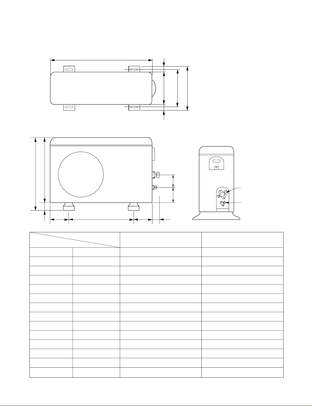
Dimensions
(1) Indoor Unit
-9-
W
L7 L6 L8 L9
D
L1
L2
L3
L10L11
L4L5
H
Gas side
Liquid side
(2) Outdoor Unit
MODEL
DIM
W mm 870 870
H mm 655 880
D mm 320 320
L1 mm 370 370
L2 mm 340 340
L3 mm 25 25
L4 mm 630 855
L5 mm 25 25
L6 mm 546 546
L7 mm 162 162
L8 mm 162 162
L9 mm 54 54
L10 mm 74.5 74.5
L11 mm 79 79
ALL MODELS LS-T246QEG
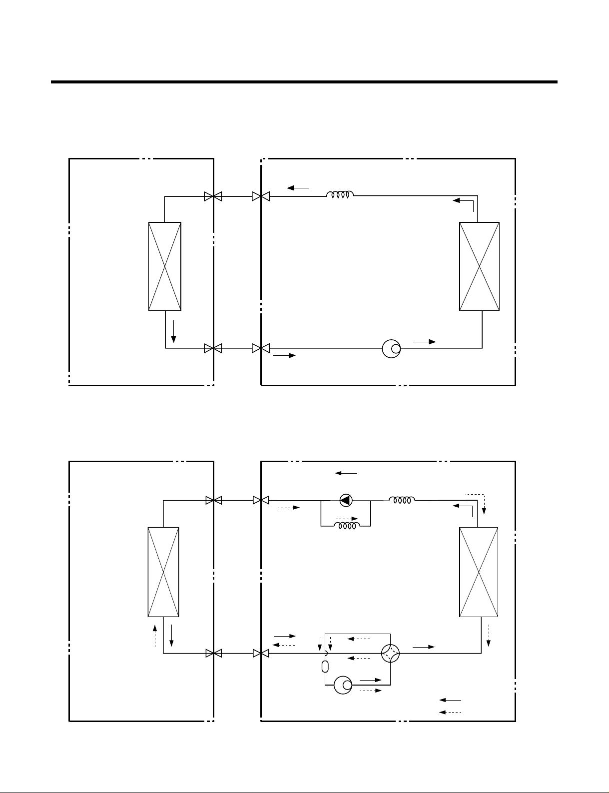
Refrigeration Cycle Diagram
-10-
INDOOR UNIT OUTDOOR UNIT
INDOOR UNIT OUTDOOR UNIT
HEAT
EXCHANGE
(EVAPORATOR)
HEAT
EXCHANGE
(EVAPORATOR)
HEAT
EXCHANGE
(CONDENSER)
HEAT
EXCHANGE
(CONDENSER)
COMPRESSOR
COMPRESSOR
ACCUMU
LATOR
GAS SIDE
GAS SIDE
VALVE
LIQUID SIDE
LIQUID SIDE
VALVE
CAPILLARY TUBE
CAPILLARY TUBE
CHECK VALVE
(Heating Model only)
COOLING
HEATING
REVERSING
VALVE
(Heating Model Only)
(1) Cooling Only Models
(2) Cooling & Heating Models
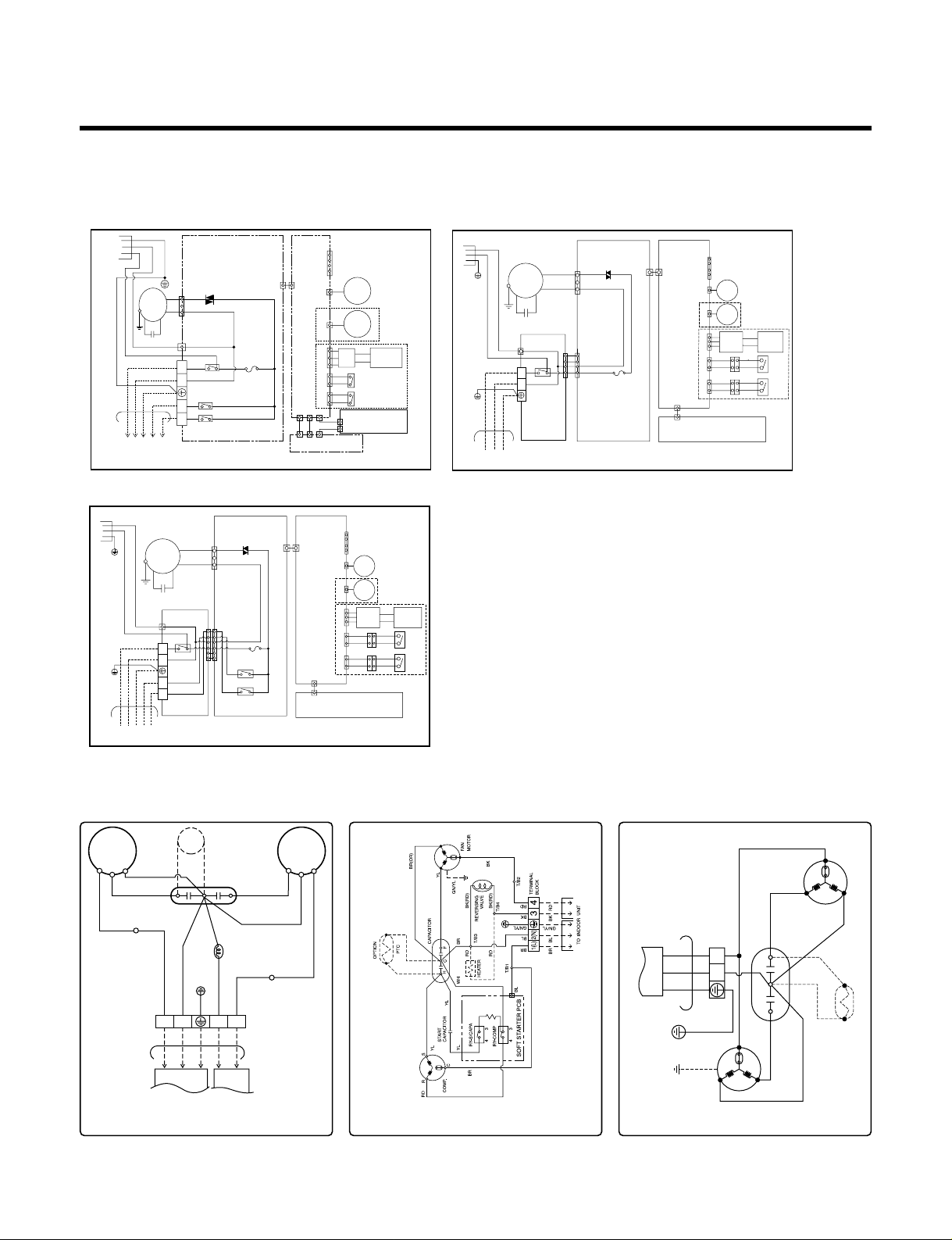
Wiring Diagram
-11-
POWER
BR
BRBLBKRDGN/YL
BL
1(L) 2(N)
34
MOTOR
CN-MOTOR
CN-TAB1
CN-AC/DC
CN-AC/DC
CN-TH
THERMISTOR
STEP
MOTOR
STEP
MOTOR
H.V.
ASM
RD
AIR
CLEAN
(
PLASMA
)
SAFETY S/W1
SAFETY S/W2
BK
BK
BK
BK
BK
CN-U/D
CN-L/R
CN-DISP
DISPLAY PWB ASM
SUB PWB ASM
CN-TELE
CN-LCD
INDOOR WIRING DIAGRAM
RY-4WAY
RY-FAN
T/BLOCK
TO OUTDOOR UNIT
TRIAC
AC PWB ASM DC PWB ASM
OR
BK
BR
4
RY-COMP
FUSE
250V T2A
3
YL
SH-CAPA
GN/YL
BR
(
BK/Plained
)
GN/YL
BL
(
WH/Ribbed
)
MOTOR
OR
RD
BK
BK BK
BK BK
BK BK
BK BK
POWER
BR(BK/Plained)
BL(WH/Ribbed)
BK
YL
SH-CAPA
T/BOARD
T-BLOCK
CN-MOTOR
THERMISTOR
STEP
MOTOR
CN-ACDC1
CN-ACDC2
CN-THCN-U/DCN-L/RCN-HVBCN-12V
CN-DISP
DISPLAY PWB ASM.
P/No : 3854A20238J
CN-CONT
TRIAC
AC PWB ASM. DC PWB ASM.
CN-TAB
RY-COMP
TO OUTDOOR UNIT
INDOOR WIRING DIAGRAM
43
1(L)
BR
BR
BL
GN/YL
2(N)
FUSE
250V T2A
STEP
MOTOR
H.V.
ASM.
S/W1
S/W2
AIR
CLEAN
(PLASMA)
GN/YL
GN/YL
MOTOR
OR
RD
BK
BK BK
BK BK
BK BK
BK BK
POWER
GN/YL
GN/YL
BR(BK/Plained)
BL(WH/Ribbed)
BK
YL
SH-CAPA
T/BOARD
T-BLOCK
RY-4WAY
RY-FAN
CN-MOTOR
THERMISTOR
STEP
MOTOR
CN-ACDC1
CN-ACDC2
CN-THCN-U/DCN-L/RCN-HVBCN-12V
CN-DISP
DISPLAY PWB ASM.
P/No : 3854A20238H
CN-CONT
TRIAC
AC PWB ASM. DC PWB ASM.
CN-TAB
RY-COMP
TO OUTDOOR UNIT
INDOOR WIRING DIAGRAM
43
1(L)
BR
BR
BL
BK
RD
GN/YL
2(N)
3 4
FUSE
250V T2A
STEP
MOTOR
H.V.
ASM.
S/W1
S/W2
AIR
CLEAN
(PLASMA)
(1) Indoor Unit
COMP
C
S
R
FAN
MOTOR
BR
BR
BL
RD
BK
GN/YL
BR
BL
RD
BK
YL
BK(RD)
BK
(RD)
BR(OR)
GN/YL
REVERSING
YL
CAPACITOR
RD
TO INDOOR UNIT
OUTDOOR WIRING DIAGRAM
TERMINAL
BLOCK
HCF
PTC
1(L)2(N
)
34
VALVE
T / B 2
T / B 1
OUTDOOR WIRING DIAGRAM (LS-T246QEG) OUTDOOR WIRING DIAGRAM (3854A20167B)
RD
BR(OR)
OPTION
PTC
YL
BK
(BR)
C
R
S
COMP.
BK
YL
FAN
MOTOR
TP
HC F
TO INDOOR UNIT
TERMINAL
BLOCK
BR
BL
GN/YL
GN/YL
GN/YL
T/B
CAPACITOR
1(L)
2(N)
(2) Outdoor Unit
Cooling
Heatpump

Operation Details
1. MAIN UNIT FUNCTION
• DISPLAY
1) C/O Model
Operation Indicator
• ON while in appliance operation, OFF while in appliance pause.
• Flashing while in disconnection or short in Thermistor. (3 sec off / 0.5 sec on)
Sleep Timer Indicator
• ON while in sleep timer mode, OFF when sleep timer cancel or appliance operation pause.
Timer Indicator
• ON while in timer mode (on/off), OFF when timer mode is completed or canceled.
Comp. Running Incidator
• While in appliance operation, ON while in outdoor unit compressor running, OFF while in compressor off.
2) H/P Model
Operation Indicator
• ON while in appliance operation, OFF while in appliance pause.
• Flashing while in disconnection or short in Thermistor. (3 sec off / 0.5 sec on)
Sleep Timer Indicator
• ON while in sleep timer mode, OFF when sleep timer cancel or appliance operation pause.
Timer Indicator
• ON while in timer mode (on/off), OFF when timer mode is completed or canceled.
Defrost Indicator
• OFF except when hot start during heating mode operation or while in defrost control.
■ Cooling Mode Operation
• When the intake air temperature reaches 0.5°C below the setting temp, the compressor and the outdoor fan
stop.
• When it reaches 0.5°C above the setting temp, they start to operate again.
Compressor ON Temp ➲ Setting Temp+0.5°C
Compressor OFF Temp ➲ Setting Temp-0.5°C
• While in compressor running, operating with the airflow speed set by the remote control. While in compressor
not running, operating with the low airflow speed regardless of the setting.
■ Healthy Dehumidification Mode
• When the dehumidification operation input by the remote control is received, the intake air temperature is
detected and the setting temp is automatically set according to the intake air temperature.
26°C ≤ Intake Air Temp ➲ 25°C
24°C ≤ Intake Intake Air Temp<26°C ➲ Intake Air Temp-1°C
18°C ≤ Intake Intake Air Temp<24°C ➲ Intake Air Temp-0.5°C
Intake Air Temp<18°C ➲ 18°C
-12-

• While in compressor off, the indoor fan repeats low airflow speed and pause.
• While the intake air temp is between compressor on temp. and compressor off temp., 10-min dehumidifica-
tion operation and 4-min compressor off repeat.
Compressor ON Temp. ➲ Setting Temp+0.5°C
Compressor OFF Temp. ➲ Setting Temp-0.5°C
• In 10-min dehumidification operation, the indoor fan operates with the low airflow speed.
■ Heating Mode Operation
• When the intake air temp reaches +3°…above the setting temp, the compressor is turned off. When below
the setting temp, the compressor is turned on.
Compressor ON Temp. ➲ Setting Temp.
Compressor OFF Temp. ➲ Setting Temp.+3°C
• While in compressor on, the indoor fan is off when the indoor pipe temp. is below 20°C, when above 28°C,it
operates with the low or setting airflow speed. When the indoor pipe temp is between 20°C and 28°C, it operates with Super-Low(while in sleep mode, with the medium airflow speed).
• While in compressor off, the indoor fan is off when the indoor pipe temp is below 33°C, when above 35°C,it
operates with the low airflow speed.
• If overloaded while in heating mode operation, in order to prevent the compressor from OLP operation, the
outdoor fan is turned on/off according to the indoor pipe temp.
• While in defrost control, both of the indoor and outdoor fans are turned off.
■ Defrost Control
• While in heating mode operation in order to protect the evaporator pipe of the outdoor unit from freezing,
reversed to cooling cycle to defrost the evaporator pipe of the outdoor unit.
• After 40 min heating mode operation, at 4 min interval, whether to carry out defrost control or not and the time
of defrost control are determined according to the following conditions.
1) While in heating mode operation, the maximum of the indoor pipe temperature is measured and it is com-
pared with the present indoor pipe temperature to get the difference of the indoor pipe temperatures (=the
maximum temperature of indoor pipe ? the present temperature of indoor pipe), according to which, whether
to carry out defrost control or not is determined.
2) According to the need of defrost control shown above and the elapsed time of heating mode operation at that
moment, the defrost control time is determined.
3) When the determined time of defrost control is below 7 min, heating mode operation continues without carry-
ing out defrost control. According to the procedure stated above, the determination is made again. When the
defrost control time is 7 min or longer, defrost control is then carried out.
• While in defrost control, the minimum temp of the indoor pipe is measured and it is compared with the present
temp of the indoor pipe to get the difference of the indoor pipe temperatures (=the present temperature of the
indoor pipe ? the minimum temperature of the indoor pipe). When the difference is 5°C or higher, defrost control is completed and heating mode operation is carried out.
• While in defrost control, if the defrost time determined before the start of defrost control is completed, defrost
control stops and heating mode operation is carried out regardless of the above condition.
• When the indoor pipe temp is 42°C or above, defrost control is not carried out even if the condition is one of
the defrost conditions above.
• While in defrost control, the compressor is on and the indoor fan, the outdoor fan, and the 4 way valve are off.
-13-

-14-
■ Fuzzy Operation (C/O Model)
• According to the temperature set by Fuzzy rule, when the intake air temp is 0.5°C or more below the setting
temp, the compressor is turned off. When 0.5°C or more above the setting temp, the compressor is turned on.
Compressor ON Temp ➲ Setting Temp + 0.5°C
Compressor OFF Temp ➲ Setting Temp + 0.5°C
• At the beginning of Fuzzy mode operation, the setting temperature is automatically selected according to the
intake air temp at that time.
26°C ≤ Intake Air Temp ➲ 25°C
24°C ≤ Intake Air Temp< 26°C ➲ Intake Air Temp + 1°C
22°C ≤ Intake Air Temp< 24°C ➲ Intake Air Temp + 0.5°C
18°C ≤ Intake Air Temp< 22°C ➲ Intake Air Temp
Intake Air Temp<18°C ➲ 18°C
• When the Fuzzy key (Temperature Control key) is input after the initial setting temperature is selected, the
Fuzzy key value and the intake air temperature at that time are compared to select the setting temperature
automatically according to the Fuzzy rule.
• While in Fuzzy operation, the airflow speed of the indoor fan is automatically selected according to the
temperature.
■ Fuzzy Operation (H/P Model)
• When any of operation mode is not selected like the moment of the power on or when 3 hrs has passed since
the operation off, the operation mode is selected.
• When determining the operation mode, the compressor, the outdoor fan, and the 4 way valve are off and only
the indoor fan is operated for 15 seconds. Then an operation mode is selected according to the intake air
temp at that moment as follows.
24°C ≤ Inatake Air Temp ➲ Fuzzy Operation for Cooling
21°C ≤ Inatake Air Temp<24°C ➲ Fuzzy Operation for Dehumidification
Inatake Air Temp<21°C ➲ Fuzzy Operation for Heating
• If any of the operation modes among cooling / dehumidification / heating mode operations is carried out for 10
sec or longer before Fuzzy operation, the mode before Fuzzy operation is operated.
1) Fuzzy Operation for Cooling
• According to the setting temperature selected by Fuzzy rule, when the intake air temp is 0.5°C or more below
the setting temp, the compressor is turned off. When 0.5°C or more above the setting temp, the compressor
is turned on.
Compressor ON Temp ➲ Setting Temp +0.5°C
Compressor OFF Temp ➲ Setting Temp + 0.5°C
• At the beginning of Fuzzy mode operation, the setting temperature is automatically selected according to the
intake air temp at that time.
26°C≤ Intake Air Temp ➲ 25°C
24°C≤ Intake Air Temp<26°C ➲ Intake Air Temp + 1°C
22°C≤ Intake Air Temp<24°C ➲ Intake Air Temp + 0.5°C
18°C≤ Intake Air Temp<22°C ➲ Intake Air Temp
Intake Air Temp<18°C ➲ 18°C
• When the Fuzzy key (Temperature Control key) is input after the initial setting temperature is selected, the
Fuzzy key value and the intake air temperature at that time are compared to select the setting temperature
automatically according to the Fuzzy rule.
• While in Fuzzy operation, the airflow speed of the indoor fan is automatically selected according to the temperature.

-15-
2) Fuzzy Operation for Dehumidification
• According to the setting temperature selected by Fuzzy rule, when the intake air temp is 0.5°C or more below
the setting temp, the compressor is turned off. When 0.5°C or more above the setting temp, the compressor
is turned on.
Compressor ON Temp ➲ Setting Temp + 0.5°C
Compressor OFF Temp ➲ Setting Temp+0.5°C
• At the beginning of Fuzzy mode operation, the setting temperature is automatically selected according to the
intake air temp at that time.
26°C ≤ Intake Air Temp ➲ 25°C
24°C ≤ Intake Air Temp<26°C ➲ Intake Air T emp+1°C
22°C ≤ Intake Air Temp<24°C ➲ Intake Air Temp+0.5°C
18°C ≤ Intake Air Temp<22°C ➲ Intake Air Temp
Intake Air Temp<18°C ➲ 18°C
• When the Fuzzy key (Temperature Control key) is input after the initial setting temperature is selected, the
Fuzzy key value and the intake air temperature at that time are compared to select the setting temperature
automatically according to the Fuzzy rule.
• While in Fuzzy operation, the airflow speed of the indoor fan repeats the low airflow speed or pause as in
dehumidification operation.
3) Fuzzy Operation for Heating
• According to the setting temperature selected by Fuzzy rule, when the intake air temp is 3°Cormoreabove
the setting temp, the compressor is turned off. When below the setting temp, the compressor is turned on.
Compressor ON Temp ➲ Setting Temp
Compressor OFF Temp ➲ Setting Temp + 3°C
• At the beginning of Fuzzy mode operation, the setting temperature is automatically selected according to the
intake air temp at that time.
20°C≤Intake Air Temp ➲ Intake Air Temp + 0.5°C
Intake Air Temp<20°C ➲ 20°C
• When the Fuzzy key (Temperature Control key) is input after the initial setting temperature is selected, the
Fuzzy key value and the intake air temperature at that time are compared to select the setting temperature
automatically according to the Fuzzy rule.
• While in Fuzzy operation, the airflow speed of the indoor fan is set to the high or the medium according to the
intake air temperature and the setting temperature.
■ Airflow Speed Selection
• The airflow speed of the indoor fan is set to high, medium, low, or chaos (auto) by the input of the airflow
speed selection key on the remote control.
■ On-Timer Operation
• When the set time is reached after the time is input by the remote control, the appliance starts to operate.
• The timer LED is on when the on-timer is input. It is off when the time set by the timer is reached.
• If the appliance is operating at the time set by the timer, the operation continues.
-16-
■ Off-Timer Operation
• When the set time is reached after the time is input by the remote control, the appliance stops operating.
• The timer LED is on when the off-timer is input. It is off when the time set by the timer is reached.
• If the appliance is on pause at the time set by the timer, the pause continues.
■ Off-Timer ↔ On-Timer Operation
• When the set time is reached after the on/off time is input by the remote control, the on/off-timer operation is
carried out according to the set time.
■ Sleep Timer Operation
• When the sleep time is reached after <1,2,3,4,5,6,7,0(cancel) hr> is input by the remote control while in appliance operation, the operation of the appliance stops.
• While the appliance is on pause, the sleep timer mode cannot be input.
• While in cooling mode operation, 30 min later since the start of the sleep timer, the setting temperature
increases by 1°C. After another 30 min elapse, it increases by 1°C again.
• When the sleep timer mode is input while in cooling cycle mode, the airflow speed of the indoor fan is set to the
low.
• When the sleep timer mode is input while in heating cycle mode, the airflow speed of the indoor fan is set to
the medium.
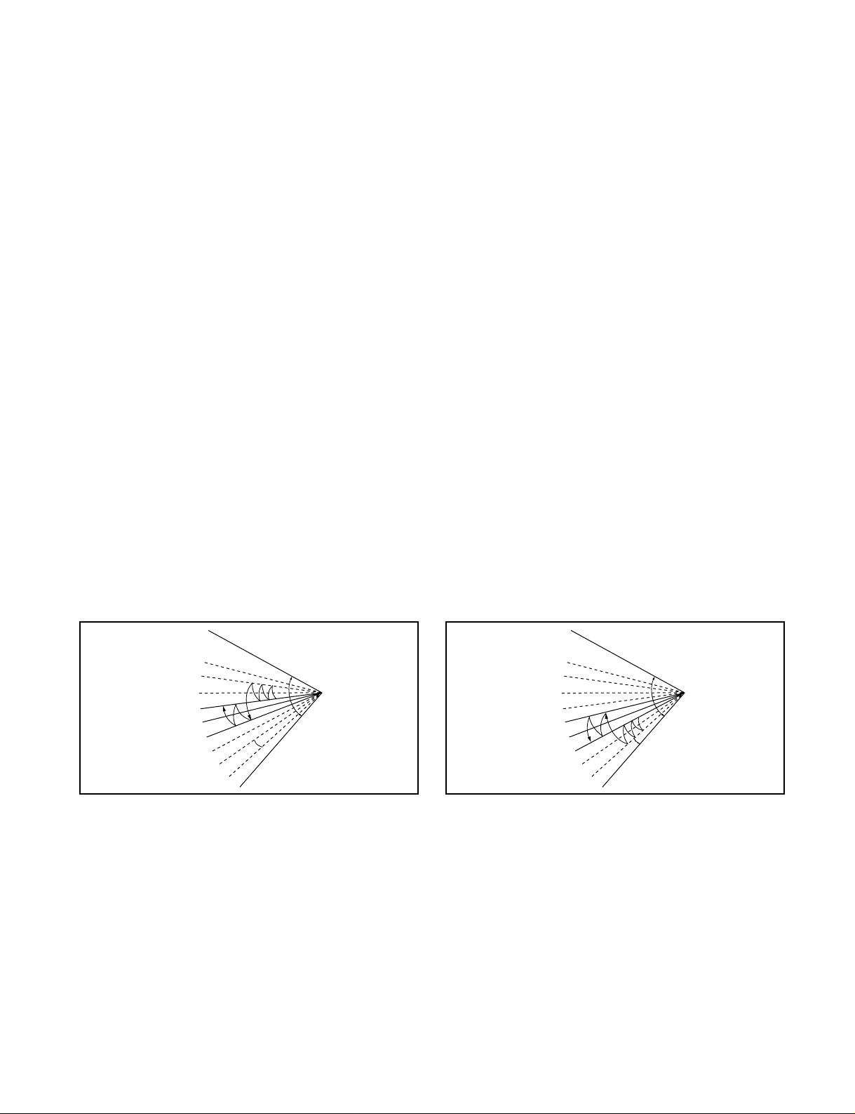
■ Chaos Swing Mode
• By the Chaos Swing key input, the upper/lower vane automatically operates with the Chaos Swing or they are
fixed to the desired direction.
• While in Chaos Swing mode, the angles of cooling and heating cycle operations are different.
■ Chaos Natural Wind Mode
• When the Chaos Natural Wind mode is selected and then operated, the high, medium, or low speed of the airflow mode is operated for 2~15 sec. randomly by the Chaos Simulation.
CLOSED
OPEN
< Cooling Mode >
8°
CLOSED
OPEN
< Heating Mode >
8°
-17-
■ Jet Cool Mode Operation (C/O Model)
• If the Jet Cool key is input at any operation mode while in appliance operation, the Jet Cool mode operates.
• In the Jet Cool mode, the indoor fan is operated at super-high speed for 30 min at cooling mode operation.
• In the Jet Cool mode operation, the room temperature is controlled to the setting temperature, 18°C
• When the sleep timer mode is input while in the Jet Cool mode operation, the Jet Cool mode has the priority.
• When the Jet Cool key is input, the upper/lower vanes are reset to those of the initial cooling mode and then
operated in order that the air outflow could reach further.
■ Jet Cool Mode Operation (H/P Model)
• While in heating mode or Fuzzy operation, the Jet Cool key cannot be input. When it is input while in the other
mode operation (cooling, dehumidification, ventilation), the Jet Cool mode is operated.
• In the Jet Cool mode, the indoor fan is operated at super-high speed for 30 min at cooling mode operation.
• In the Jet Cool mode operation, the room temperature is controlled to the setting temperature, 18
°C.
• When the sleep timer mode is input while in the Jet Cool mode operation, the Jet Cool mode has the priority.
• When the Jet Cool key is input, the upper/lower vanes are reset to those of the initial cooling mode and then
operated in order that the air outflow could reach further.
■ Forced Operation
• Operation procedures when the remote control can't be used.
• The operation will be started if the power button is pressed.
• If you want to stop operation, re-press the button.
• While in forced operation, the key input by the remote control has no effect and the buzzer sounds 10 times to
indicate the forced operation.
■ Test operation
•
During the TEST OPERATION, the unit operates in cooling mode at high speed fan, regardless of room temperature and resets in 18±1 minutes.
•
During test operation, if remote controller signal is received, the unit operates as remote controller sets.
If you want to use this operation, open the front panel upward and Press the power button let it be pressed for
about 3 seconds.
•
If you want to stop the operation, re-press the button.
■ Auto restart
•
In case the power comes on again after a power failure, Auto Restarting Operation is the function to operate
procedures automatically to the previous operating conditions.
■ Air Cleaner Operation
•
When an air cleaner function is selected during Air Conditioner operation
- Plasma air cleaner function will be operated while in any operation mode with selecting the function.
- The function is to be stopped while it is operating with selecting the function.
•
When an air cleaner function is selected during operation off
- The function will be only operated.
•
When inlet grille of air conditioner is opened during plasma operation, High Voltage Generator(H.V.B) is to be
stopped. When inlet grille of air conditioner is closed during plasma operation, High Voltage Generator(H.V.B)
will be operated again.
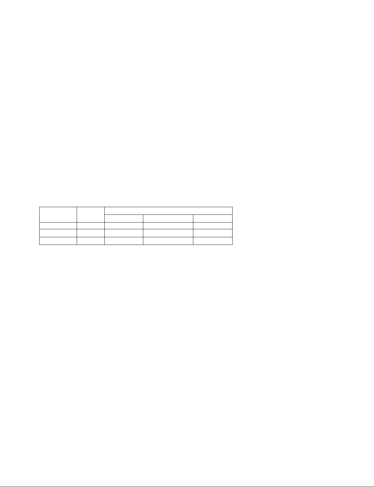
Heat pumpModel
Cooling Model
Room Temp. ≥ 24°C21°C ≤Room Temp. < 24°C Room Temp.< 21°C
Operating mode Cooling Cooling Healthy Dehumidification Heating
Indoor FAN Speed
High High High High
Setting Temperature
22°C22°C23°C24°C

-18-
■ Remote Control Operation Mode
• When the remote control is selected by the slide switch on the main unit, the appliance operates according to
the input by the remote control.
■ Protection of the evaporator pipe from frosting
• If the indoor pipe temp is below 0°C in 7 min. after the compressor operates without any pause while in cooling cycle operation mode, the compressor and the outdoor fan are turned off in order to protect the indoor
evaporator pipe from frosting.
• When the indoor pipe temp is 7°C or higher after 3 min. pause of the compressor, the compressor and the
outdoor fan is turned on according to the condition of the room temperature.
■ Buzzer Sounding Operation
• When the appliance-operation key is input by the remote control, the short "beep-beep-" sounds.
• When the appliance-pause key is input by the remote control, the long "beep—" sounds.
• When a key is input by the remote control while the slide switch on the main unit of the appliance is on the
forced operation position, the error sound "beep-beep-beep-beep-beep-" is made 10 times to indicate that the
remote control signal cannot be received.

Display Function
-19-
Self-diagnosis Function
3sec 3sec 3sec
(once)
Error
Code
1
Error Display LED
(Indoor body operation LED)
Error contents
• Indoor room temperature
thermistor open/short
• Indoor pipe temperature
thermistor open/short.
• Indoor Thermistor
assembly check
SVC check point
1. Heating Model 2. Cooling Model
• Cooling, Soft Dry, Fan, Heating • Cooling, Soft Dry, Fan
• Sleep Mode • Sleep Mode
• Timer Mode • Timer Mode
• Hot-start, Defrost
• PLASMA Mode • PLASMA Mode
• Telephone Control Mode • Telephone Control Mode
Operation Indicator
Timer Indicator
Sleep Timer Indicator
Defrost Indicator
PLASMA Indicator
Telephone control
Indicator
Telephone control
Indicator
Operation Indicator
Timer Indicator
Sleep Timer Indicator
Compressor on Indicator
PLASMA Indicator
OUTDOOR
PLASMA PLASMA
1) Selection of the best location
1. Indoor unit
• Do not have any heat or steam near the unit.
• Select a place where there are no obstacles in front of
the unit.
• Make sure that condensation drainage can be conveniently routed away.
Do not install near a doorway.
• Ensure that the space around the left and right of the
unit is more than "A". The unit should be installed as
high on the wall as possible, allowing a minimum of
"B" from ceiling.
• Use a stud finder to locate studs to prevent unnecessary damage to the wall.
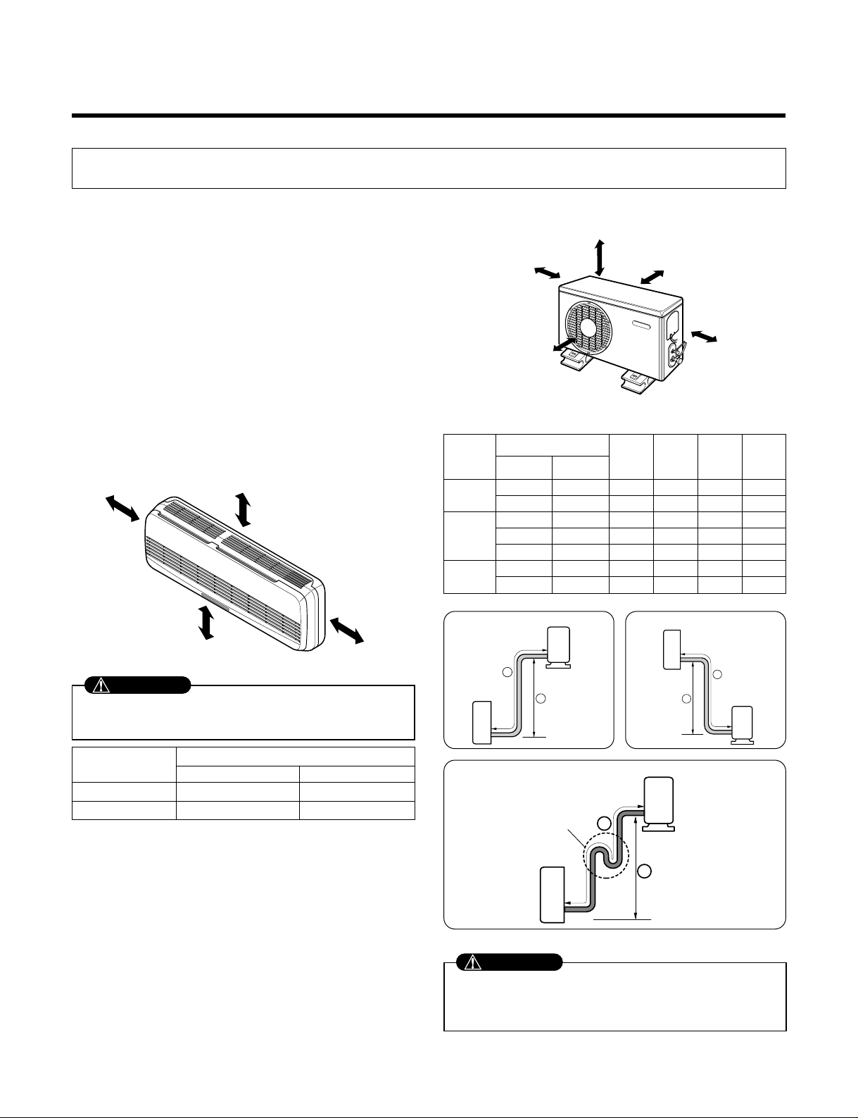
2. Outdoor unit
• If an awning is built over the unit to prevent direct sunlight or rain exposure, make sure that heat radiation
from the condenser is not restricted.
• Ensure that the space around the back and sides is
more than 10cm. The front of the unit should have
more than 70cm of space.
• Do not place animals and plants in the path of the
warm air.
• Take the air conditioner weight into account and select
a place where noise and vibration are minimum.
• Select a place so that the warm air and noise from the
air conditioner do not disturb neighbors.
2) Piping length and elevation
Installation
1. Installation of indoor, Outdoor unit
-20-
More than "A"
More than "B"
More than 2.3m
More than "B"
More than 10cm More than 10cm
More
than 60cm
More than 60cm
More than 70cm
Install the indoor unit on the wall where the height
from the floors more than 2.3 meters.
CAUTION
• Capacity is based on standard length and maximum
allowance length is on the basis of reliability.
• Oil trap should be installed every 5~7 meters.
CAUTION
Grade
Clearance(cm)
AB
7K~28K 10 5
30K~38K 30 12
Pipe Size
Capacity
(Btu/h)
GAS LIQUID
Max.
Length
A (m)
Additional
Refrigerant
(g/m)
Max.
Elevation
B (m)
Standard
Length
(m)
7k~14k
3/8"(Ø9.52) 1/4"(Ø6.35) 4or7.5 7 15 20
1/2"(Ø12.7) 1/4"(Ø6.35) 4or7.5 7 15 20
1/2"(Ø12.7) 1/4"(Ø6.35) 4or7.5 15 30 20
18k~28k 5/8"(Ø15.88) 1/4"(Ø6.35) 4or 7.5 15 30 20
5/8"(Ø15.88) 3/8"(Ø9.52) 4or7.5 15 30 30
30k~38k
5/8"(Ø15.88) 3/8"(Ø9.52) 7.5 15 30 30
3/4"(Ø19.05) 3/8"(Ø9.52) 7.5 15 30 50
If case more than 5m
Outdoor unit
Indoor unit
A
B
Outdoor unit
Indoor unit
A
B
A
Oil trap
Outdoor unit
Indoor unit
B
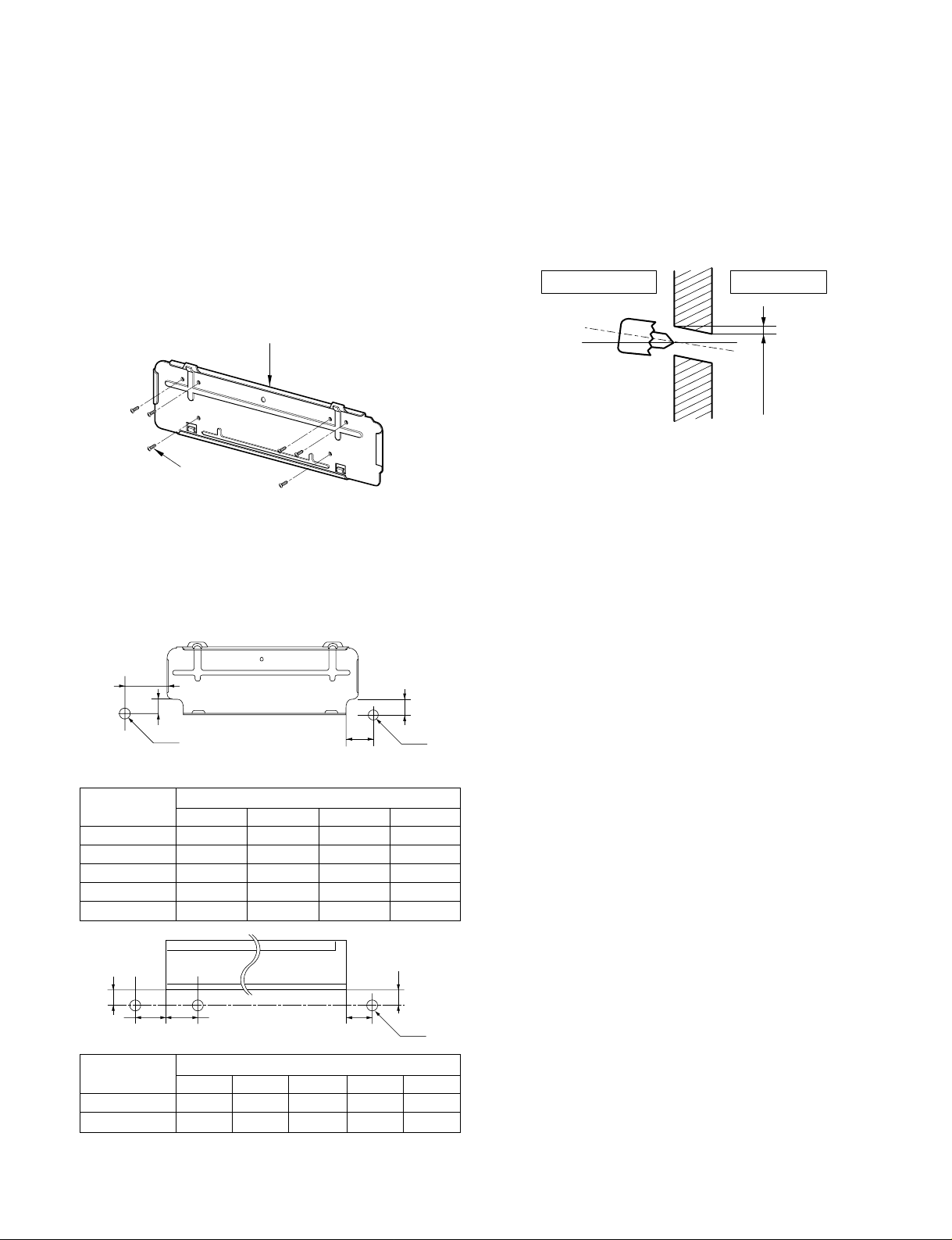
3) How to fix installation plate
The wall you select should be strong and solid enough
to prevent vibration
1. Mount the installation plate on the wall with four
type A screws. If mounting the unit on a concrete
wall, use anchor bolts.
• Mount the installation plate horizontally by aligning
thecenterlineusingalevel.
2. Measure the wall and mark the centerline. It is
also important to use caution concerning the
location of the installation plate-routing of the
wiring to power outlets is through the walls typically. Drilling the hole through the wall for piping
connections must be done safely.
4) Drill a hole in the wall
• Drill the piping hole with a ø70mm hole core drill. Drill
the piping hole at either the right or the left with the
hole slightly slanted to the outdoor side.
-21-
Installation Plate
Type "A" screw
5-7mm
(3/16"~5/16")
Indoor
WALL
Outdoor
Installation plate
Ø70mm
Left rear piping Right rear piping
C
D
B
A
Ø70mm
Ø70mm
Left rear piping
Right rear piping
CE A
B
D
Installation plateInstallation plate
ABCD
SJ 90 20 80 20
SL, SK 45 40 80 20
SQ 75 12 80 12
SR 0 40 20 40
ST 105 0 210 0
CHASSIS
(Grade)
Distance (mm)
ABCDE
SM 180 115 - 115 50
SN 180 115 195 115 -
CHASSIS
(Grade)
Distance (mm)
-22-
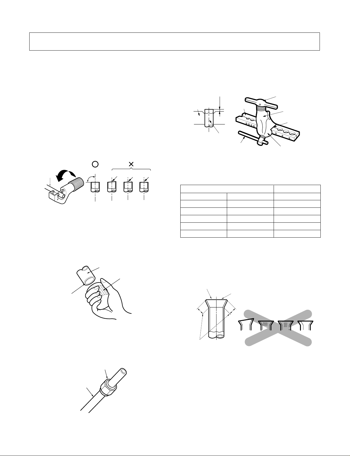
2. Flaring Work and Connection of Piping
1) Flaring work
Main cause for refrigerant leakage is due to defect in
the flaring work. Carry out correct flaring work using the
following procedure.
1. Cut the pipes and the cable.
•
Use the piping kit accessory or pipes purchased locally.
• Measure the distance between the indoor and the
outdoor unit.
• Cut the pipes a little longer than the measured
distance.
• Cut the cable 1.5m longer than the pipe length.
2. Burr removal
• Completely remove all burrs from the cut cross section of pipe/tube.
• Put the end of the copper tube/pipe in a downward
direction as you remove burrs in order to avoid dropping burrs into the tubing.
3. Putting nut on
• Remove flare nuts attached to indoor and outdoor
unit, then put them on pipe/tube having completed
burr removal.
(not possible to put them on after flaring work)
4. Flaring work
• Firmly hold copper pipe in a die in the dimension
showninthetableabove.
• Carry out flaring work using flaring tool as shown
below.
5. Check
• Compare the flared work with figure below.
• If flare is noted to be defective, cut off the flared sec-
tion and re-flare it.
Copper
pipe
90°
Slanted Uneven Rough
Bar
Copper pipe
Clamp handle
Red arrow mark
Cone
Yoke
Handle
Bar
"A"
Inclined
Inside is shiny without scratches
Smooth all round
Even length
all round
Surface
damaged
Cracked Uneven
thickness
= Improper flaring =
Pipe
Reamer
Point down
Flare nut
Copper tube
mm inch mm
Ø6.35 1/4 0~0.5
Ø9.52 3/8 0~0.5
Ø12.7 1/2 0~0.5
Ø15.88 5/8 0~1.0
Ø19.05 3/4 1.0~1.3
Outside diameter
 Loading...