


Room Air Conditioner
SERVICE MANUAL
MODEL : LS-L1260CL/CM/CN/CD/CS LS-L1260HL/HM/HN/HD/HS

Contents |
|
|
|
|
|
|
|
|
|
|
|
|
||||
Functions .................................................................................................................................3 |
||||||||||||||||
|
|
|
|
|
|
|
|
|
............................................................................................................ |
|||||||
Product Specification |
|
|
|
|
|
|
|
5 |
||||||||
|
|
|
.............................................................................................................................. |
|||||||||||||
Dimensions |
|
|
|
|
|
|
|
|
|
|
|
|
|
6 |
||
|
|
|
|
|
|
|
|
|
|
|
|
.................................................................................................. |
||||
Refrigeration Cycle Diagram |
|
|
|
|
8 |
|||||||||||
|
|
|
|
........................................................................................................................ |
||||||||||||
Wiring Diagram |
|
|
|
|
|
|
|
|
|
|
|
|
9 |
|||
|
|
|
|
|
|
.................................................................................................................. |
||||||||||
Operation Details |
|
|
|
|
|
|
|
|
|
|
10 |
|||||
|
|
|
|
|
................................................................................................................... |
|||||||||||
Display Function |
|
|
|
|
|
|
|
|
|
|
|
17 |
||||
|
|
|
|
|
|
|
|
|
|
........................................................................................................ |
||||||
Self-diagnosis Function |
|
|
|
|
|
|
17 |
|||||||||
|
|
............................................................................................................................. |
||||||||||||||
Installation |
|
|
|
|
|
|
|
|
|
|
|
|
|
|
18 |
|
|
............................................................................................................................... |
|||||||||||||||
Operation |
|
|
|
|
|
|
|
|
|
|
|
|
|
|
|
34 |
|
|
|
|
|
|
|
|
|
|
|
|
|
|
............................................................................... |
||
Disassembly of the parts (Indoor Unit) |
|
|
36 |
|||||||||||||
|
|
|
|
|
|
|
................................................................................................................. |
|||||||||
2-way, 3-way Valve |
|
|
|
|
|
|
|
|
|
39 |
||||||
|
|
|
|
|
|
|
|
|
|
|
|
|
............................................................................................... |
|||
Cycle Troubleshooting Guide |
|
|
|
46 |
||||||||||||
|
|
|
|
|
|
|
|
|
|
|
|
|
|
|
............................................................................. |
|
Electronic Parts Troubleshooting Guide |
|
47 |
||||||||||||||
|
|
|
|
|
|
|
|
|
|
|
..................................................................................................... |
|||||
Electronic Control Device |
|
|
|
|
|
54 |
||||||||||
|
|
|
|
|
|
|
|
............................................................................................................... |
||||||||
Schematic Diagram |
|
|
|
|
|
|
|
|
56 |
|||||||
|
|
|
|
|
|
|
|
|
|
|
|
|
|
|
|
........................................................................... |
Exploded View & Replacement Parts List |
58 |
|||||||||||||||
-2-
Functions
Indoor Unit
Operation ON/OFF by Remote controller
Sensing the Room Temperature
• Room temperature sensor. (THERMISTOR)
Room temperature control
• Maintains the room temperature in accordance with the Setting Temp.
Starting Current Control
• Indoor fan is delayed for 5 sec at the starting.
Time Delay Safety Control
• Restarting is inhibited for approx. 3 minutes.
Indoor Fan Speed Control
• High, Med, Low, CHAOS
Operation indication Lamps (LED)
--- Lights up in operation
--- Lights up in Sleep Mode
--- Lights up in Timer Mode
 --- Lights up in Defrost Mode (for Heating Model) OUTDOOR --- Lights up in compressor operation (for Cooling Model)
Soft Dry Operation Mode
• Intermittent operation of fan at low speed.
Sleep Mode Auto Control
•The fan is switched to low(Cooling), med(Heating) speed.
•The unit will be stopped after 1, 2, 3, 4, 5, 6, 7 hours.
Natural Air Control by CHAOS Logic
•The fan is switched to intermittent or irregular operation
•The fan speed is automatically switched from high to low speed.
Airflow Direction Control
•The louver can be set at the desired position or swing up and down automatically.
Defrost(Deice) control (Heating)
ƒU Both the indoor and outdoor fan
stops during defrosting.
Hot-start Control (Heating)
ƒU The indoor fan stops until the evaporator pipe temperature will be reached at 28°C.
-3-
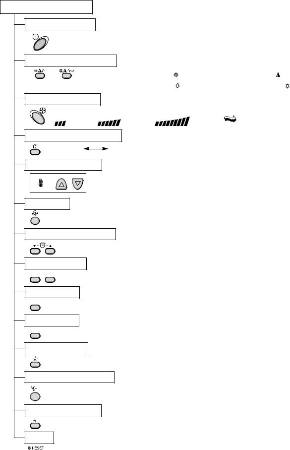
Remote Controller
Operation ON/OFF
Operation Mode Selection
(Cooling (Heating model only) model only)
Cooling Operation Mode.( |
) |
Auto Operation Mode.( |
) |
Soft Dry Operation Mode.( |
) |
Heating Operation Mode.( |
) |
Fan Speed Selection |
|
|
|
(Low) |
(Med) |
(High) |
(CHAOS) |
Room, Temperature Display |
|
|
|
: (High: 39°C |
LOW : 11°C) |
|
|
Temperature Setting
TEMPERATURE HIGH LOW
Cooling |
|
|
Down to 18°C |
Heating |
|
|
Down to 16°C |
|
|
|
|
||||
|
|
Up to 30°C |
|
|
Up to 30°C |
||
|
|
|
|
|
|
||
|
|
|
|
|
|
JET COOL
Setting the Time or Timer
Timer Selection
ON 

 OFF
OFF
: OFF, ON, OFF 
 ON
ON
Timer Setting
SET
Timer Cancel
CANCEL
: Cancel Sleep Mode, Timer ON or Timer OFF
Sleep Operation
: 1, 2, 3, 4, 5, 6, 7, Off Timer
Airflow Direction Control
Fan Operation Mode
: Fan Operates without cooling or heating.
Reset
-4-
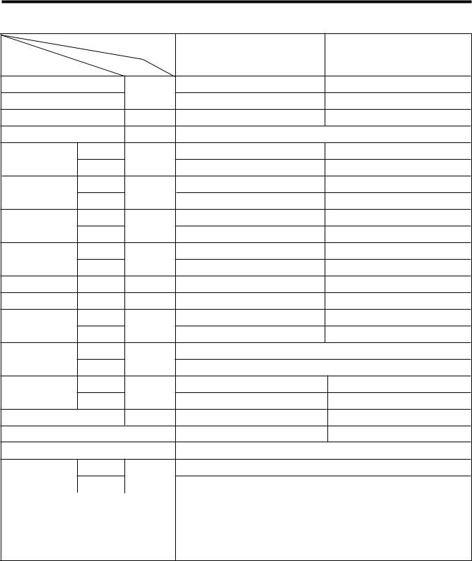
Product Specifications
SPEC. AT 230V
|
Model Name |
LS-L1260CL |
LS-L1260HL |
||
|
|
|
|||
Item |
|
Unit |
|
|
|
Cooling Capacity |
|
Btu/h |
12,000 |
12,000 |
|
Heating Capacity |
|
- |
13,000 |
||
|
|
||||
Moisture Removal |
|
l/h |
1.5 |
1.5 |
|
Power Source |
|
Ø, V, Hz |
|
1Ø, 220-240V, 50Hz |
|
Air Circulation |
Indoor |
m3/min |
9.5 |
9.5 |
|
Outdoor |
25 |
25 |
|||
|
|
||||
Noise Level |
Indoor |
dB (A)¡ 3 |
36 |
36 |
|
Outdoor |
46 |
46 |
|||
|
|
||||
Input |
Cooling |
W |
1,190 |
1,200 |
|
Heating |
- |
1,120 |
|||
|
|
||||
Running |
Cooling |
A |
5.4 |
5.5 |
|
Current |
Heating |
- |
5.0 |
||
|
|||||
E.E.R. |
Cooling |
Btu/hW |
10.1 |
10.0 |
|
C.O.P |
Heating |
|
- |
3.4 |
|
Motor Output |
Indoor |
W |
13 |
13 |
|
Outdoor |
26 |
26 |
|||
|
|
||||
Dimensions |
Indoor |
mm |
|
888 x 287 x 170 |
|
(W¡¿H¡¿D) |
Outdoor |
|
770 x 540 x 245 |
||
|
|
|
|||
Net. Weight |
Indoor |
kg |
9 |
9 |
|
Outdoor |
34 |
35 |
|||
|
|
||||
Refrigerant (R22) |
|
g |
740 |
830 |
|
Airflow Direction Control (Up & Down) |
§ |
§ |
|||
Remocon Type |
|
|
|
L.C.D Wireless |
|
Service Valve |
Liquid |
inch(mm) |
|
1/4" (6.35) |
|
Gas |
|
1/2" (12.7) |
|||
|
|
|
|||
Sleeping Operation |
§ |
|
§ |
|
|
|
|
Drain Hose |
§ |
|
§ |
|
|
|
|
Connecting Cable |
|
1.0mm2 |
|
|
|
|
|
Power Cord |
|
1.0mm2 |
|
-5-
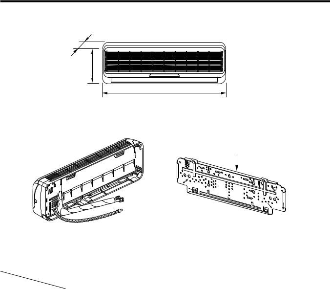
Dimensions
(1) Indoor Unit
D
H
W
Installation plate
|
MODEL |
12K Btu Series |
|
||
DIM |
Unit |
|
|
|
|
W |
mm |
888 |
|
|
|
H |
mm |
287 |
|
|
|
D |
mm |
170 |
|
|
|
-6-
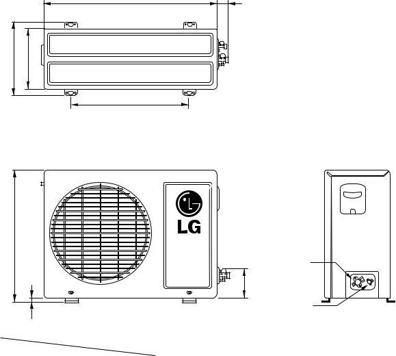
(2) Outdoor Unit
|
W |
L2 |
L1 |
D |
|
|
L3 |
|
H
L4
Gas side
(3-way valve)
L5
Liquid side (2-way valve)
|
MODEL |
12K Btu Series |
|
DIM |
unit |
||
|
|||
|
|
|
|
W |
mm |
770 |
|
|
|
|
|
H |
mm |
540 |
|
|
|
|
|
D |
mm |
245 |
|
|
|
|
|
L1 |
mm |
287 |
|
|
|
|
|
L2 |
mm |
64 |
|
|
|
|
|
L3 |
mm |
518 |
|
|
|
|
|
L4 |
mm |
10 |
|
|
|
|
|
L5 |
mm |
100 |
|
|
|
|
-7-
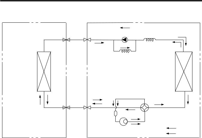
Refrigeration Cycle Diagram
INDOOR UNIT |
OUTDOOR UNIT |
LIQUID SIDE |
CHECK VALVE |
(Heating Model only) |
|
2-WAY VALVE |
|
|
CAPILLARY TUBE |
HEAT |
HEAT |
EXCHANGE |
EXCHANGE |
(EVAPORATOR) |
(CONDENSER) |
GAS SIDE |
|
|
|
3-WAY VALVE |
ACCUMU |
|
REVERSING |
|
VALVE |
||
|
|
||
|
LATOR |
|
(Heating Model Only) |
|
|
COMPRESSOR |
COOLING |
|
|
HEATING |
|
|
|
|
|
Pipe size(Diameter:Ø) |
MAX. |
Max |
||
MODEL |
Piping length |
Elevation |
|||
|
|
||||
Gas(inch) |
Liquid(inch) |
||||
|
(m) |
(m) |
|||
|
|
|
|||
|
|
|
|
|
|
12K Btu SERIES |
1/2" |
1/4" |
15 |
7 |
|
|
|
|
|
|
|
-8-

Wiring Diagram
(1) Indoor Unit
1. LS-L1260CL |
|
|
|
|
|
POWER |
|
CN-MOTOR |
|
|
FORCED |
|
|
MAIN PCB |
|||
|
|
OPERATION |
|||
GN/YL |
|
ASM |
|
AUTO |
|
|
TRIAC |
|
RESTART |
||
OR |
|
REMOTE |
|||
|
|
||||
MOTOR |
|
|
|
CONTROL |
|
|
|
|
|
||
|
BK |
|
|
TH1 |
|
|
|
|
ZNR |
THERMISTOR |
|
|
|
|
|
||
BR |
YL |
|
|
CN- |
|
|
|
|
|||
SH-CAPA. |
TAB1 |
|
CN-U/D |
STEP |
|
|
MOTOR |
||||
BR |
|
|
|
||
BL |
|
CN- |
|
|
|
BL |
|
CN-TAB2 |
|
|
|
|
|
4 |
3 |
|
|
RY-COMP. FUSE
AC250V/T2A
BR |
BL |
GN/YL |
CN-DISP1 |
|
1(L) 2(N) |
|
PILLAR |
||
|
TERMINAL |
|||
BR |
BL |
GN/YL |
||
DISPLAY PCB ASM |
||||
|
|
|
||
INDOOR WIRING DIAGRAM
TO OUTDOOR UNIT |
3854A30077A |
|
(2) Outdoor Unit
1. LS-L1260CL
|
BL |
|
|
|
|
|
CAPACITOR |
|
|
|
RD |
H C |
F |
RD |
R |
S |
|
|
|
|
COMP. |
|
BL |
|
|
BL |
|
|
|
C
BR
OLP
FAN YL MOTOR
BR
1
BR |
BL |
GN/YL |
|
1(L) |
2(N) |
TERMINAL |
|
BLOCK |
|||
|
|
||
BR |
BL |
GN/YL |
BLACK
TO INDOOR UNIT
OUTDOOR WIRING DIAGRAM
3854A30077B
2. LS-L1260HL |
|
|
|
|
||
POWER |
|
CN-MOTOR |
|
|
|
FORCED |
|
|
|
MAIN PCB |
|||
|
|
|
OPERATION |
|||
GN/YL |
|
|
ASM |
|
AUTO |
|
|
|
TRIAC |
|
RESTART |
||
OR |
|
|
REMOTE |
|||
|
|
|
||||
MOTOR |
|
|
|
|
CONTROL |
|
|
|
|
|
|
||
BR |
BK |
|
|
|
TH1 |
|
|
|
|
ZNR |
THERMISTOR |
||
|
|
|
|
|||
BR |
YL |
|
|
|
CN- |
|
|
|
|
|
|||
SH-CAPA. |
CN-TAB1 |
|
|
CN-U/D |
STEP |
|
|
|
MOTOR |
||||
BL |
|
|
|
|
||
BL |
|
CN-TAB2 |
|
|
|
|
BR |
|
|
|
FUSE |
|
|
|
|
|
|
|
|
|
|
|
4 |
3 |
AC250V/T2A |
|
|
RY-COMP.
4WAY-CN |
RY-4WAY |
BR |
BL |
GN/YL |
BK |
RD |
RY-FAN |
|
|
|
|
|
|
||
|
|
|
|
|
CN-DISP1 |
|
1(L) 2(N) |
|
3 |
4 |
PILLAR |
||
|
TERMINAL |
|||||
BR |
BL |
GN/YL |
BK |
RD |
||
DISPLAY PCB ASM |
||||||
|
|
|
|
|
||
INDOOR WIRING DIAGRAM
TO OUTDOOR UNIT |
3854AR6093Y |
|
2. LS-L1260HL
COMP. |
PTC |
|
|
|
GN/YL |
FAN |
|
|
|
|
|
||||
|
|
|
|
MOTOR |
|||
C |
R |
BL BL |
|
|
|
||
|
|
|
|
|
|||
S |
|
|
|
|
|
|
|
|
|
|
CAPACITOR |
|
|||
OLP |
|
H |
C |
F |
|
RD |
BL YL |
|
|
|
|
|
|||
|
|
|
|
|
|
||
BR RD BL |
|
|
|
|
|
|
|
|
|
BK |
|
|
|
|
|
|
|
(RD) |
|
|
|
|
|
|
|
REVERSING |
VALVE |
|
|
RD |
|
|
|
|
|
BL |
|
||
|
|
|
|
|
|
YL |
|
|
BR |
BL GN/YL |
BK |
YL |
|
|
|
|
(RD) |
|
TERMINAL |
|
|||
|
1(L) 2(N) |
3 |
|
4 |
|
||
|
|
BLOCK |
|
||||
|
|
|
|
|
|
|
|
|
BR |
BL GN/YL |
BK |
RD |
|
|
|
TO INDOOR UNIT
OUTDOOR WIRING DIAGRAM
3854A30077D
-9-
Operation Details
1. MAIN UNIT FUNCTION
• DISPLAY
1) C/O Model
Operation Indicator
•On while in appliance operation, off while in appliance pause
•Flashing while in disconnection or short in Thermistor (3 sec off / 0.5 sec on)
Sleep Timer Indicator
• On while in sleep timer mode, off when sleep timer cancel or appliance operation pause
Timer Indicator
• On while in timer mode (on/off), off when timer mode is completed or canceled.
Comp. Running Incidator
•While in appliance operation, on while in outdoor unit compressor running, off while in compressor off
2)H/P Model
Operation Indicator
•On while in appliance operation, off while in appliance pause
•Flashing while in disconnection or short in Thermistor (3 sec off / 0.5 sec on)
Sleep Timer Indicator
• On while in sleep timer mode, off when sleep timer cancel or appliance operation pause
Timer Indicator
• On while in timer mode (on/off), off when timer mode is completed or canceled
Defrost Indicator
•Off except when hot start during heating mode operation or while in defrost control
■Cooling Mode Operation
•When the intake air temperature reaches 0.5°C below the setting temp, the compressor and the outdoor fan stop.
•When it reaches 0.5°C above the setting temp, they start to operate again.
Compressor ON Temp |
Setting Temp+0.5°C |
Compressor OFF Temp |
Setting Temp-0.5°C |
•While in compressor running, operating with the airflow speed set by the remote control. While in compressor not running, operating with the low airflow speed regardless of the setting.
■Healthy Dehumidification Mode
•When the dehumidification operation input by the remote control is received, the intake air temperature is
detected and the setting temp is automatically set according to the intake air temperature.
26°C ≤ Intake Air Temp |
25°C |
24°C ≤ Intake Intake Air Temp<26°C |
Intake Air Temp-1°C |
18°C ≤ Intake Intake Air Temp<24°C |
Intake Air Temp-0.5°C |
Intake Air Temp<18°C |
18°C |
-10-
•While in compressor off, the indoor fan repeats low airflow speed and pause.
•While the intake air temp is between compressor on temp. and compressor off temp., 10-min dehumidification operation and 4-min compressor off repeat.
Compressor ON Temp. |
Setting Temp+0.5°C |
Compressor OFF Temp. |
Setting Temp-0.5°C |
•In 10-min dehumidification operation, the indoor fan operates with the low airflow speed.
■Heating Mode Operation
•When the intake air temp reaches +3°…above the setting temp, the compressor is turned off. When below the setting temp, the compressor is turned on.
Compressor ON Temp. |
Setting Temp. |
Compressor OFF Temp. |
Setting Temp.+3°C |
•While in compressor on, the indoor fan is off when the indoor pipe temp. is below 20°C, when above 28°C , it operates with the low or setting airflow speed. When the indoor pipe temp is between 20°C and 28°C, it operates with Super-Low(while in sleep mode, with the medium airflow speed).
•While in compressor off, the indoor fan is off when the indoor pipe temp is below 33°C, when above 35°C , it operates with the low airflow speed.
•If overloaded while in heating mode operation, in order to prevent the compressor from OLP operation, the outdoor fan is turned on/off according to the indoor pipe temp.
•While in defrost control, both of the indoor and outdoor fans are turned off.
■Defrost Control
•While in heating mode operation in order to protect the evaporator pipe of the outdoor unit from freezing, reversed to cooling cycle to defrost the evaporator pipe of the outdoor unit.
•After 40 min heating mode operation, at 4 min interval, whether to carry out defrost control or not and the time of defrost control are determined according to the following conditions.
1)While in heating mode operation, the maximum of the indoor pipe temperature is measured and it is compared with the present indoor pipe temperature to get the difference of the indoor pipe temperatures (=the maximum temperature of indoor pipe ? the present temperature of indoor pipe), according to which, whether to carry out defrost control or not is determined.
2)According to the need of defrost control shown above and the elapsed time of heating mode operation at that moment, the defrost control time is determined.
3)When the determined time of defrost control is below 7 min, heating mode operation continues without carrying out defrost control. According to the procedure stated above, the determination is made again. When the defrost control time is 7 min or longer, defrost control is then carried out.
•While in defrost control, the minimum temp of the indoor pipe is measured and it is compared with the present temp of the indoor pipe to get the difference of the indoor pipe temperatures (=the present temperature of the indoor pipe ? the minimum temperature of the indoor pipe). When the difference is 5°C or higher, defrost control is completed and heating mode operation is carried out.
•While in defrost control, if the defrost time determined before the start of defrost control is completed, defrost control stops and heating mode operation is carried out regardless of the above condition.
•When the indoor pipe temp is 42°C or above, defrost control is not carried out even if the condition is one of the defrost conditions above.
•While in defrost control, the compressor is on and the indoor fan, the outdoor fan, and the 4 way valve are off.
-11-
■ Fuzzy Operation (C/O Model)
•According to the temperature set by Fuzzy rule, when the intake air temp is 0.5°C or more below the setting temp, the compressor is turned off. When 0.5°C or more above the setting temp, the compressor is turned on.
Compressor ON Temp |
Setting Temp + 0.5°C |
Compressor OFF Temp |
Setting Temp + 0.5°C |
•At the beginning of Fuzzy mode operation, the setting temperature is automatically selected according to the intake air temp at that time.
26°C ≤ Intake Air Temp |
25°C |
24°C ≤ Intake Air Temp < 26°C |
Intake Air Temp + 1°C |
22°C ≤ Intake Air Temp < 24°C |
Intake Air Temp + 0.5°C |
18°C ≤ Intake Air Temp < 22°C |
Intake Air Temp |
Intake Air Temp<18°C |
18°C |
•When the Fuzzy key (Temperature Control key) is input after the initial setting temperature is selected, the Fuzzy key value and the intake air temperature at that time are compared to select the setting temperature automatically according to the Fuzzy rule.
•While in Fuzzy operation, the airflow speed of the indoor fan is automatically selected according to the temperature.
■Fuzzy Operation (H/P Model)
•When any of operation mode is not selected like the moment of the power on or when 3 hrs has passed since the operation off, the operation mode is selected.
•When determining the operation mode, the compressor, the outdoor fan, and the 4 way valve are off and only the indoor fan is operated for 15 seconds. Then an operation mode is selected according to the intake air temp at that moment as follows.
24°C ≤ Inatake Air Temp |
Fuzzy Operation for Cooling |
21°C ≤ Inatake Air Temp<24°C |
Fuzzy Operation for Dehumidification |
Inatake Air Temp<21°C |
Fuzzy Operation for Heating |
•If any of the operation modes among cooling / dehumidification / heating mode operations is carried out for 10 sec or longer before Fuzzy operation, the mode before Fuzzy operation is operated.
1)Fuzzy Operation for Cooling
•According to the setting temperature selected by Fuzzy rule, when the intake air temp is 0.5°C or more below the setting temp, the compressor is turned off. When 0.5°C or more above the setting temp, the compressor is turned on.
Compressor ON Temp |
Setting Temp +0.5°C |
Compressor OFF Temp |
Setting Temp + 0.5°C |
•At the beginning of Fuzzy mode operation, the setting temperature is automatically selected according to the intake air temp at that time.
26°C≤ Intake Air Temp |
25°C |
24°C≤ Intake Air Temp<26°C |
Intake Air Temp + 1°C |
22°C≤ Intake Air Temp<24°C |
Intake Air Temp + 0.5°C |
18°C≤ Intake Air Temp<22°C |
Intake Air Temp |
Intake Air Temp<18°C |
18°C |
•When the Fuzzy key (Temperature Control key) is input after the initial setting temperature is selected, the Fuzzy key value and the intake air temperature at that time are compared to select the setting temperature automatically according to the Fuzzy rule.
•While in Fuzzy operation, the airflow speed of the indoor fan is automatically selected according to the temperature.
-12-
2) Fuzzy Operation for Dehumidification
•According to the setting temperature selected by Fuzzy rule, when the intake air temp is 0.5°C or more below the setting temp, the compressor is turned off. When 0.5°C or more above the setting temp, the compressor is turned on.
Compressor ON Temp |
Setting Temp + 0.5°C |
Compressor OFF Temp |
Setting Temp+0.5°C |
•At the beginning of Fuzzy mode operation, the setting temperature is automatically selected according to the intake air temp at that time.
26°C ≤ Intake Air Temp |
25°C |
24°C ≤ Intake Air Temp<26°C |
Intake Air Temp+1°C |
22°C ≤ Intake Air Temp<24°C |
Intake Air Temp+0.5°C |
18°C ≤ Intake Air Temp<22°C |
Intake Air Temp |
Intake Air Temp<18°C |
18°C |
•When the Fuzzy key (Temperature Control key) is input after the initial setting temperature is selected, the Fuzzy key value and the intake air temperature at that time are compared to select the setting temperature automatically according to the Fuzzy rule.
•While in Fuzzy operation, the airflow speed of the indoor fan repeats the low airflow speed or pause as in dehumidification operation.
3)Fuzzy Operation for Heating
•According to the setting temperature selected by Fuzzy rule, when the intake air temp is 3°C or more above the setting temp, the compressor is turned off. When below the setting temp, the compressor is turned on.
Compressor ON Temp |
Setting Temp |
Compressor OFF Temp |
Setting Temp + 3°C |
•At the beginning of Fuzzy mode operation, the setting temperature is automatically selected according to the intake air temp at that time.
20°C≤ Intake Air Temp |
Intake Air Temp + 0.5°C |
Intake Air Temp<20°C |
20°C |
•When the Fuzzy key (Temperature Control key) is input after the initial setting temperature is selected, the Fuzzy key value and the intake air temperature at that time are compared to select the setting temperature automatically according to the Fuzzy rule.
•While in Fuzzy operation, the airflow speed of the indoor fan is set to the high or the medium according to the intake air temperature and the setting temperature.
■Airflow Speed Selection
•The airflow speed of the indoor fan is set to high, medium, low, or chaos (auto) by the input of the airflow speed selection key on the remote control.
■On-Timer Operation
•When the set time is reached after the time is input by the remote control, the appliance starts to operate.
•The timer LED is on when the on-timer is input. It is off when the time set by the timer is reached.
•If the appliance is operating at the time set by the timer, the operation continues.
-13-

■Off-Timer Operation
•When the set time is reached after the time is input by the remote control, the appliance stops operating.
•The timer LED is on when the off-timer is input. It is off when the time set by the timer is reached.
•If the appliance is on pause at the time set by the timer, the pause continues.
■Off-Timer <=> On-Timer Operation
•When the set time is reached after the on/off time is input by the remote control, the on/off-timer operation is carried out according to the set time.
■Sleep Timer Operation
•When the sleep time is reached after <1,2,3,4,5,6,7,0(cancel) hr> is input by the remote control while in appliance operation, the operation of the appliance stops.
•While the appliance is on pause, the sleep timer mode cannot be input.
•While in cooling mode operation, 30 min later since the start of the sleep timer, the setting temperature increases by 1°C. After another 30 min elapse, it increases by 1°C again.
•When the sleep timer mode is input while in cooling cycle mode, the airflow speed of the indoor fan is set to the low.
•When the sleep timer mode is input while in heating cycle mode, the airflow speed of the indoor fan is set to the medium.
■Chaos Swing Mode
•By the Chaos Swing key input, the upper/lower vane automatically operates with the Chaos Swing or they are fixed to the desired direction.
•While in Chaos Swing mode, the angles of cooling and heating cycle operations are different.
< Cooling Mode > |
< Heating Mode > |
|
|
|
|
CLOSED |
CLOSED |
|
7° |
7° |
OPEN |
OPEN |
■Chaos Natural Wind Mode
•When the Chaos Natural Wind mode is selected and then operated, the high, medium, or low speed of the airflow mode is operated for 2~15 sec. randomly by the Chaos Simulation.
-14-

■Jet Cool Mode Operation (C/O Model)
•If the Jet Cool key is input at any operation mode while in appliance operation, the Jet Cool mode operates.
•In the Jet Cool mode, the indoor fan is operated at super-high speed for 30 min at cooling mode operation.
•In the Jet Cool mode operation, the room temperature is controlled to the setting temperature, 18°C
•When the sleep timer mode is input while in the Jet Cool mode operation, the Jet Cool mode has the priority.
•When the Jet Cool key is input, the upper/lower vanes are reset to those of the initial cooling mode and then operated in order that the air outflow could reach further.
■Jet Cool Mode Operation (H/P Model)
•While in heating mode or Fuzzy operation, the Jet Cool key cannot be input. When it is input while in the other mode operation (cooling, dehumidification, ventilation), the Jet Cool mode is operated.
•In the Jet Cool mode, the indoor fan is operated at super-high speed for 30 min at cooling mode operation.
•In the Jet Cool mode operation, the room temperature is controlled to the setting temperature, 18°C.
•When the sleep timer mode is input while in the Jet Cool mode operation, the Jet Cool mode has the priority.
•When the Jet Cool key is input, the upper/lower vanes are reset to those of the initial cooling mode and then operated in order that the air outflow could reach further.
■Auto Restarting Operation
•When the power is restored after a sudden power failure while in appliance operation, the mode before the power failure is kept on the memory and the appliance automatically operates in the mode on the memory.
•The slide switch on the main unit of the appliance should be on the Auto Restarting position in order that the Auto Restarting operation is available.
•Operation Mode that is kept on the memory
-State of Operation ON/OFF
-Operation Mode/Setting Temp/Selected Airflow Speed
-Sleep Timer Mode/Remaining Time of Sleep Timer (unit of hour)
•If no input by the remote control or no switching of the slide switch within 7 hr after the appliance operates by the Auto Restarting operation, the appliance is forced to stop at the moment of 7-hr elapse.
FORCED
OPERATION
AUTO
RESTART
REMOTE
CONTROL
Slide Switch
■Forced Operation (C/O Model)
•To operate the appliance by force in case that the remote control is lost, the forced operation selection switch is on the main unit of the appliance to operate the appliance in the standard conditions.
•When the power is supplied while the slide switch is on the forced operation position, or when the slide switch position is switched to the Auto Restarting position (or test operation) or switched from the remote control position to the forced operation position while the power is on, the forced operation is carried out.
•When the slide switch position is switched from the forced operation position to the Auto Restarting position or the remote control position, the forced operation is canceled and the appliance stops operating.
•The forced operation is carried out in cooling mode with the setting temperature 22°C and the high speed of airflow.
•While in forced operation, the key input by the remote control has no effect and the buzzer sounds 10 times to indicate the forced operation.
-15-
■Forced Operation (H/P Model)
•To operate the appliance by force in case that the remote control is lost, the forced operation selection switch is on the main unit of the appliance to operate the appliance in the standard conditions.
•When the power is supplied while the slide switch is on the forced operation position, or when the slide switch position is switched to the Auto Restarting (or test operation) position or switched from the remote control position to the forced operation position while the power is on, the forced operation is carried out.
•When the slide switch position is switched from the forced operation position to the Auto Restarting position or the remote control position, the forced operation is canceled and the appliance stops operating.
•The forced operation is carried out in cooling mode with the setting temperature 22°C and the high speed of airflow.
•In the forced operation mode, the indoor fan is operated at low speed for around 15 sec and then the operation condition is set according to the intake air temperature as follows.
24°C≤ Intake Air Temp |
Cooling Mode Operation, 22°C, High Speed |
21°C≤ Intake Air Temp<24°C |
Dehumidification Operation, 23°C, High Speed |
Intake Air Temp<21°C |
Heating Mode Operation, 24°C, High Speed |
•While in forced operation, the key input by the remote control has no effect and the buzzer sounds 10 times to indicate the forced operation.
■Remote Control Operation Mode
•When the remote control is selected by the slide switch on the main unit, the appliance operates according to the input by the remote control.
■Protection of the evaporator pipe from frosting
•If the indoor pipe temp is below 0°C in 7 min. after the compressor operates without any pause while in cooling cycle operation mode, the compressor and the outdoor fan are turned off in order to protect the indoor evaporator pipe from frosting.
•When the indoor pipe temp is 7°C or higher after 3 min. pause of the compressor, the compressor and the outdoor fan is turned on according to the condition of the room temperature.
■Buzzer Sounding Operation
•When the appliance-operation key is input by the remote control, the short "beep-beep-" sounds.
•When the appliance-pause key is input by the remote control, the long "beep—" sounds.
•When a key is input by the remote control while the slide switch on the main unit of the appliance is on the forced operation position, the error sound "beep-beep-beep-beep-beep-" is made 10 times to indicate that the remote control signal cannot be received.
-16-
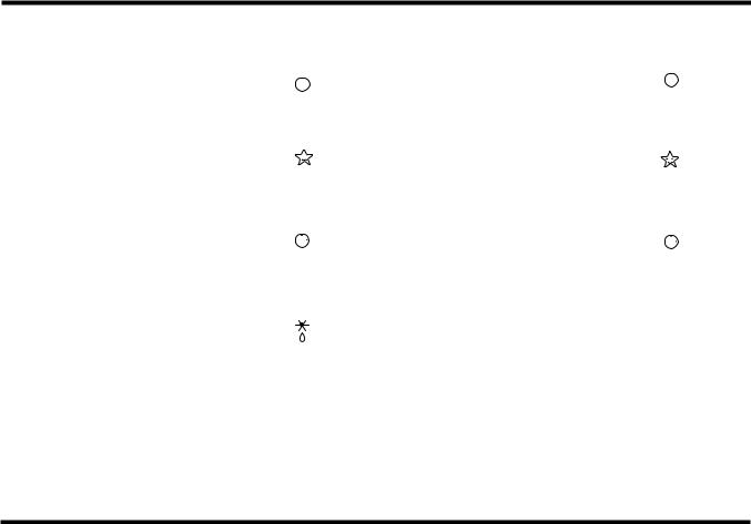
Display Function
1. Heating Model |
|
2. Cooling Model |
|
|
|
|||||
|
|
|
|
|
|
|
|
|
|
|
|
|
Operation Indicator |
|
|
|
|
Operation Indicator |
|
|
|
|
|
|
|
|
|
|
|
|
|
|
|
|
• Cooling, Soft Dry, Fan, Heating |
|
|
|
• Cooling, Soft Dry, Fan |
|
|
|
|
|
|
|
|
|
|
|
|
|
|
|
|
|
Sleep Timer Indicator |
|
|
|
|
Sleep Timer Indicator |
|
|
|
|
|
|
|
|
|
|
|
|
||
|
|
|
|
|
|
|
|
|
|
|
|
|
• Sleep Mode |
|
|
|
• Sleep Mode |
|
|
|
|
|
|
|
|
|
|
|
|
|
|
|
|
|
Timer Indicator |
|
|
|
|
Timer Indicator |
|
|
|
|
|
|
|
|
|
|
||||
|
|
|
|
|
|
|
||||
|
|
|
|
|
|
|
||||
|
|
|
|
|
|
|
|
|
||
|
|
|
|
|
|
|
|
|
|
|
|
|
|
|
|
|
|
|
|
|
|
|
|
• Timer Mode |
|
|
|
• Timer Mode |
|
|
|
|
|
|
|
|
|
|
|
|
OUT |
||
|
|
Defrost Indicator |
|
|
|
|
Compressor on Indicator |
|||
|
|
|
|
|
|
DOOR |
||||
|
|
|
|
|
|
|
|
|||
|
|
|
|
|
|
|
|
|
|
|
|
|
• Hot-start, Defrost |
|
|
|
|
|
|
|
|
Self-diagnosis Function
■Thermistor Error Indicator
•When the indoor pipe sensor or the room temperature sensor is open or is shorted, the error is indicated.
•To indicate the error, the operation LED (or the cooling LED) flashed at 3 sec interval.
•When the error is cleared, the LED stops flashing, the operation (or cooling) LED is on.
•While in appliance pause, the error is not indicated.
-17-
Installation
1. Installation of indoor, Outdoor unit
1) Selection of the best location
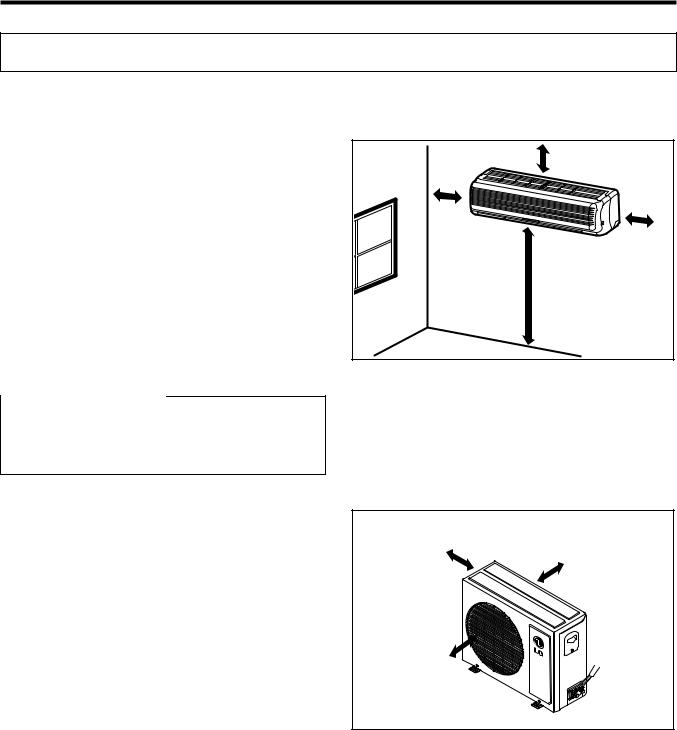
1.Indoor unit
•There should not be any heat source or steam near the unit.
•There should not be any obstacles to prevent the air circulation.
•A place where air circulation in the room will be good.
•A place where drainage can be easily obtained.
•A place where noise prevention is taken into consideration.
•Do not install the unit near the door way.
•Ensure the spaces indicated by arrows from the wall, ceiling, fence or other obstacles.
More than 5 cm |
More than |
5 cm |
More than |
5 cm |
More than 2.3 m |

 CAUTION
Install the indoor unit on the wall where the height from the floor is more than 2.3 meters.
2.Outdoor unit
•If an awning is built over the unit to prevent direct sunlight or rain exposure, be careful that heat radiation from the condenser is not restricted.
•There should not be any animals or plants which could be affected by hot air discharged.
•Ensure the correct distance is left from the wall, ceiling, fence, or other obstacles as indicated in the diagram.
More than 10 cm
More than 10 cm
More than 70 cm
-18-
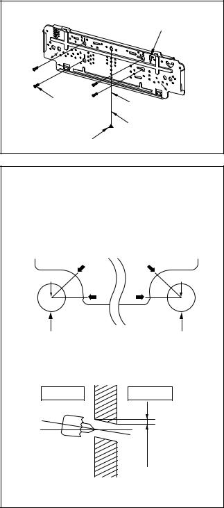
2) Indoor Unit Installation
The mounting wall should be strong and solid enough to protect it from the vibration.
1.Mount the installation plate on the wall with four Type "A" screws.
(if mounting the unit on the concrete wall, consider using anchor bolts.)
•Always mount the Installation plate horizontally by aligning the marking-off line by means of the thread and a level.
2.Drill the piping hole with 70mm dia. holecore drill.
•Line according to the arrows marked on lower the left and the right side of the Installation Plate. The meeting point of the extended line is the center of the hole.
•Drill the Piping hole at either the right or the left and the hole should be slightly slanted to the outdoor side.
Installation plate
Type "A" screw
Marking-off line Thread
Weight
The lower left and right side of Installation Plate
12K Btu
Left rear piping |
Right rear piping |
A |
A |
Center |
Center |
A |
A |
ø70mm |
ø70mm |
|
WALL |
Indoor |
Outdoor |
5-7mm
-19-
 Loading...