


 REFRIGERATOR
SERVICE MANUAL
CAUTION
PLEASE READ THE SAFETY PRECAUTIONS OF THIS MANUAL CAREFULLY BEFORE REPAIRING OR OPERATING THE REFRIGERATOR
MODELS:
LSC27910SW /01
LSC27910ST /01
LSC27910TT /01
LSC27910SB /01

ECN (Engineering Change Number)
Rev.01
Change Base Compressor (due to Back Prone Loading transportation)
Items related to this change:
•Damper,Compressor (312A)
•Stopper,Compressor (314A)
•Base Assembly,Compressor (315A)

WARNINGS AND SAFETY PRECAUTIONS .......................................................................... |
3 |
1. SPECIFICATIONS ............................................................................................................... |
4 |
2. PARTS IDENTIFICATION ................................................................................................... |
5 |
3. HOW TO INSTALL THE REFRIGERATOR ........................................................................ |
6 |
4. HOW TO DISASSEMBLE AND ASSEMBLE...................................................................... |
10 |
5. MICOM FUNCTION ............................................................................................................. |
15 |
6. EXPLANATION FOR MICOM CIRCUIT .............................................................................. |
25 |
7. ICEMAKER AND DISPENSER WORKING PRINCIPLES AND REPAIR............................ |
42 |
8. CIRCUIT .............................................................................................................................. |
48 |
9. TROUBLE DIAGNOSIS ...................................................................................................... |
49 |
10. EXPLODED VIEW ............................................................................................................. |
88 |
- 2 -

 WARNINGS AND PRECAUTIONS FOR SAFETY
Please observe the following safety precautions to use the refrigerator safely and correctly and to prevent accident or injury when servicing.
1.Be careful of an electric shock. Disconnect power cord from wall outlet and wait for more than three minutes before replacing PWB parts. Shut off the power whenever replacing and rapairing electric components.
2.When connecting power cord, wait for more than five minutes after power cord was disconnected from the wall outlet.
3.Check if the power plug or card is pinched between the refrigerator and the wall. If the cord is damaged, it could cause fire or electric shock.
4.If the wall outlet is ocerloaded, it may cause a fire. Use a dedicated circuit for the refrigerator.
5.Be sure the outlet is grounded. This is particulary important in wet or damp areas.
6.Use standard electrical components.
7.Make sure hooks are correctly engaged.
Remove dust and foreign materials from the housing and connecting parts.
8.Do not fray, damage, run over, kink, bend, pull out, or twist the power cord.
9.Please check for evidence of moisture intrusion in the electrical components. Replace the parts or mask with insulation tape if moisture intrusion was confirmed.
10.Do not touch the icemaker with hands or tools to confirm the operation of geared motor.
11.Do not suggest that customers repair their refrigerator themselves. This work requires special tools and knowledge. Non-professionals could cause fire, injury, or damage to the product.
12.Do not store flammable materials such as ether, benzene, alcohol, chemicals, gas, or medicine in the refrigerator.
13.Do not put anything on top of the refrigerator, especially something containing water, like a vase.
14.Do not put glass bottles full of water into the freezer. The contents will freeze and break the glass period.
15.When you scrap or discard the refrigerator, remove the doors and dispose of it where children are not likely to play in or around it.
- 3 -
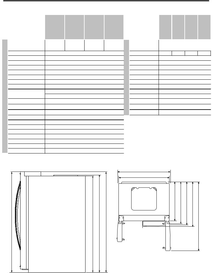
1. SPECIFICATIONS
SPECIFICATIONS
|
Color |
|
|
Dimensions |
|
|
Net Weight |
|
|
Capacity |
|
|
Refrigerant |
|
|
Climate class |
|
|
Rated Rating |
|
FEATURES |
Cooling System |
|
Temperature Control |
||
|
||
GENERAL |
Defrosting System |
|
Insulation |
||
|
||
|
Compressor |
|
|
Evaporator |
|
|
Condenser |
|
|
Lubricanting Oil |
|
|
Drier |
|
|
Capillary Tube |
|
|
First Defrost |
|
|
Defrost Cycle |
|
|
Defrosting Device |
|
|
Anti-freezing Heater |
MODELS |
LSC27910SW |
|
LSC27910ST |
|
LSC27910TT |
|
LSC27910SB |
|
Super white |
|
Stainless |
|
Titanium |
|
Black |
|
|
|
|
||||
|
|
|
|
|
|
|
|
36 x 33 x 70 in
286.6 lbs
27 cuft
R134a (185gr)
Temperate (N)
115V~ / 60Hz
Fan Cooling
MICOM control
Full Automatic
Heater Defrost
Cyclo, Pentane
LD72LACH PTC Starting Type
Fin Tube Type
Wire Condenser
Polyol Ester 310 ± 10 cc
MOLECULAR SIEVE XH-7
ID Ø0.83
4 Hours
13 - 70 Hours
Heater, Sheath
Water Tank Heater
SPECIFICATIONS
|
Case Material |
|
|
Door Material |
|
REFRIGERATOR |
Handle Type |
|
Display Graphic |
||
|
||
|
Basket, Quantity |
|
|
Ice Tray & Bank |
|
|
Magic Crisper |
|
|
Lamp |
|
|
Shelf |
|
|
Tray meat |
|
FREEZER |
Egg Bank |
|
Shelf |
||
|
Basket, Quantity |
|
|
Lamp |
MODELS |
LSC27910SW |
|
LSC27910ST |
LSC27910TT |
|
LSC27910SB |
|
|
|
|
Embo (normal) |
|
|
||
|
PCM |
|
Stainless |
|
VCM |
|
VCM |
|
|
|
|
||||
|
|
|
Vista |
|
|
|
|
|
|
|
A-LG |
|
|
|
|
|
|
|
3 full + 1half |
|
|
||
AUTO ICE MAKER+ SPACE PLUS
Yes
Yes (1) 40W/Blue
1 (Fix) + 2 (S/Out)
Yes
No
3 Plastic
Yes (1) 40W/Blue
3 EA (Wire)
|
|
|
|
912 mm (3529/32 in.) |
|
|
|
|
|
|
|
|
908 mm (3511/16 in.) |
|
|
|
|
|
|
|
|
/ |
in.) |
in.) |
in.) |
in.) |
|
|
|
|
/ |
/ |
16 |
/ |
|
|
|
|
|
2 |
8 |
8 |
5 |
8 |
|
|
|
|
1 |
5 |
5 |
5 |
|
(69mm1771 |
(68mm1741.5 |
(68mm1746.5 |
(69mm1771 |
724mm (28 |
779mm (30 |
830mm (32 |
/ |
1261mm (49 |
mm891 (35 |
||||||||
in.) |
in.) |
in.) |
in.) |
|
|
|
|
|
16 |
/ |
/ |
16 |
|
|
|
|
|
/ |
2 |
4 |
/ |
|
|
|
|
|
1 |
3 |
|
|
|
|
|
||
11 |
|
|
11 |
|
|
|
|
|
Front View |
Top View |
- 4 -
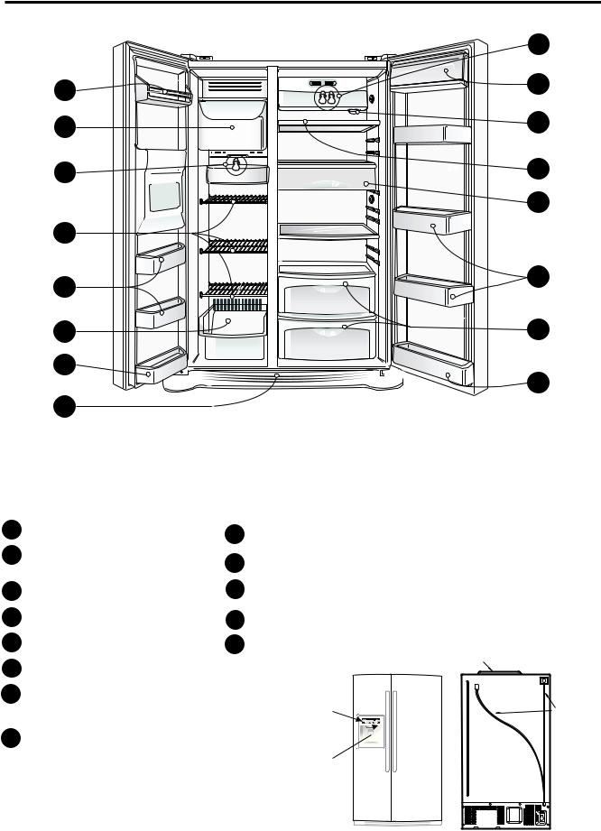
2. PARTS IDENTIFICATION
|
I |
A |
G |
|
|
B |
H |
C |
J |
|
K |
B |
|
D |
L |
|
|
E |
M |
D |
L |
|
|
F |
|
Use this page to become more familiar with the parts and features. Page references are included for your convenience.
Note: This guide covers several different models.The refrigerator you have purchased may have some or all of the items listed below. The locations of the features shown below may not match your model.
AFreezer Shelf
BIce Bin
For storage of ice cubes made by the icemaker.
Do not store anything except ice in the ice bin.
CFreezer Lamp
DFreezer Door Rack
EDrawer
FBase Grille
G Dairy Corner
For storage of dairy products
such as butter and cheese.
H Water Filter
I Refrigerator Lamp
JRefrigerator Shelf
KSnack Pan
For storage of meat or fresh food.
L Refrigerator Door Rack
M Vegetable Drawer
PWB Cover
Display Frame |
Water Tubes |
Dispenser Lamp 
Ice & Water
Dispenser Button
- 5 -
3. HOW TO INSTALL THE REFRIGERATOR
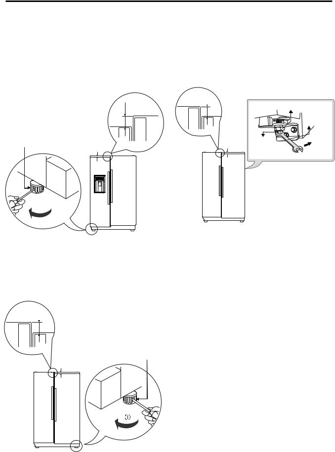
1. DOOR ALIGNMENT
Before adjust the doors, remove the Base Grille.
If the freezer compartment door is lower than the refrigerator compartment door, make them level by inserting flat blade screwdriver into the groove of the left leveling leg and rotating it clockwise.
Height difference
Left leveling |
Height |
leg |
|
|
difference |
Adjust the level when the refrigerator door is lower than the freezer door during the installation of the refrigerator.
Tools you need
•Wrench 5/16 in (8 mm)
•Wrench 3/4 in (19 mm)
Height difference
|
|
Keeper nut |
|
|
Wrench |
Height |
Adjustment |
Up |
difference |
hinge pin |
|
|
|
Down
If the freezer compartment door is higher than the refrigerator compartment door, make them level by inserting flat blade screwdriver into the groove of the right leveling leg and rotating it clockwise.
Height difference
Left leveling leg
Height
difference
Using a ¾” (19 mm) wrench, turn the keeper nut clockwise to lossen the keeper nut.
Using a 5/16” (8 mm) wrench, turn the adjustment hinge pin clockwise or counterclockwise to level the refrigerator and freezer door.
After setting the level door, turn the keeper nut counterclockwise to tighten.
Do not over tightening the door adjustment screw. The hinge pin can be pulled out. (Adjustable range of height is a maximum of ½” (1.27 cm)).
AFTER LEVELING THE DOOR HEIGHT
Make sure the front leveling legs are completely touching the floor.
- 6 -
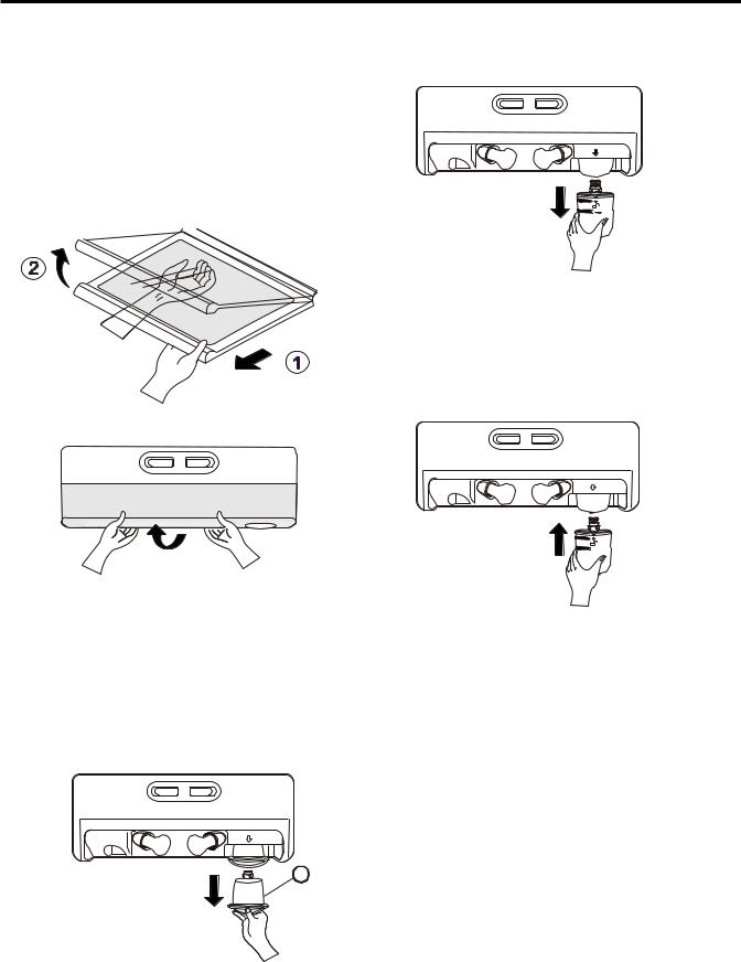
2. WATER FILTER
Before removing or installing water filter:
1.Take out the top shelf and move it to the lowest level.
2.Remove the lamp cover by pressing the tab under the cover and pulling cover to the front.
3.IMPORTANT: Turn off household water supply.
Removing the water filter:
1.For first-time installation, remove filter substitute cap
(A) by turning it counterclockwise a quarter turn and pulling it down.
2.For subsequent installation, remove old filter by slowly turning it to the left a quarter turn and pulling it down.
A
Installing the water filter
Remove red cap from the filter and insert the two tabs on the filter tip into the two slots in the refrigerator filter receptacle. You should feel the filter
entering completely. Turn the filter to the right a quarter turn clockwise to lock it into place. The locked symbol will be lined up with the indicator arrow.
After installing water filter
a)Replace the cover lamp and shelf to the initial position.
b)Dispense 2.5 gallons (9.46 L) of water to purge the system (dispense for approximately 5 minutes). Open the refrigerator door and check the shelf area for leaks.
c)After installing filter, turn on household water supply.
- 7 -
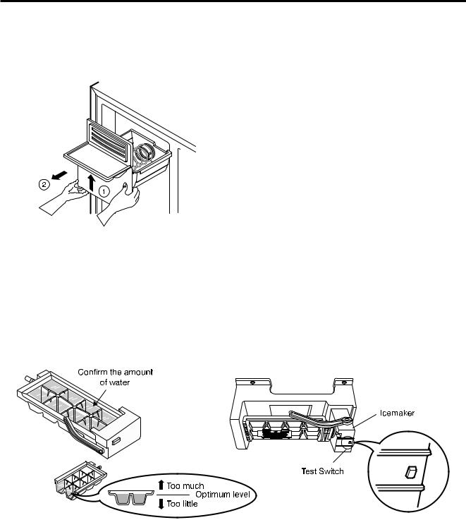
3. HOW TO CONTROL THE AMOUNT OF WATER SUPPLIED TO ICEMAKER
3-1. Confirm the amount of water supplied to the icemaker
.
1. Pull out the ice bin shelf in the upper part of the freezer compartment.
Caution: •Do not put hands or tools into the chute to confirm the operation of geared motor.
It may damage the refrigerator or hurt your hands.
2. Turn on the electricity after connecting water pipe.
1)Press the test switch under the icemaker for two seconds as shown below.
2)The bell rings (ding ~ dong), the ice tray rotates, and water comes out the icemaker water tube.
3)The water is supplied into the tray two or three times. The amount is small each time. Put a container under the ice tray and press test switch.
4)When the ice tray rotates,the water in it will spill. Collect the spilled water and discard it.
5)When ice tray has finished rotation, water comes out the water tube. Check the amount that goes into the ice tray. (Refer to the drawing below. The optimum amount is 110cc. (Almost 4 oz.)).
* It is acceptable is the adjusted water level is less than the optimum level.
- 8 -
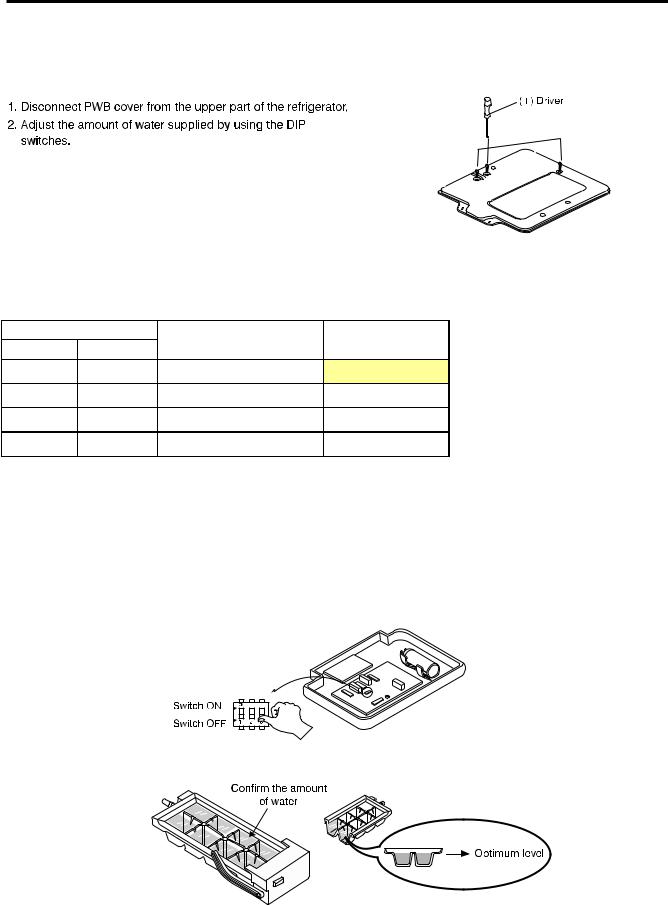
3-2 Control the amount of water supplied to the icemaker.
Caution: • Unplug the power cord from the wall outlet and wait at least three minutes before removing the main PWB cover. 310 Volts are present in the control panel.
Water Supplying Time Control Option
SWITCH |
WATER SUPPLY TIME |
NOTE |
||
SW2 |
SW1 |
|||
|
|
|||
OFF |
OFF |
6.5s |
FACTORY SETTING |
|
|
|
|
|
|
OFF |
ON |
5.5s |
|
|
|
|
|
|
|
ON |
OFF |
7.5s |
|
|
|
|
|
|
|
ON |
ON |
8.5s |
|
|
|
|
|
|
|
1)The water supplying time is set at five seconds when the refrigerator is deivered.
2)The amount of water supplied depends on the setting time and water pressure (city water pressure).
3)If the ice cubes are too small, increase the water supplying time. This happens when too little water is supplied into the ice tray.
4)If the ice cubes stick together, decrease the water supplying time. This happens when too much water is supplied into the ice tray.
Caution: When adjusting the amount of water supplied, adjust step by step. Otherwise the water may spill over.
3. When the adjustment of the control switch for the amount of water supplied is complete, check the level of water in the ice.
- 9 -
4. HOW TO DISASSEMBLY AND ASSEMBLE
1. REMOVING AND REPLACING
REFRIGERATOR DOORS
Before remove the doors, remove the Base Grille.
To remove the right (refrigerator) door:
(1) 
 (2)
(2)
(3)
(4)

 (5)
(5)
(3)
Rivet
Type 1
(4)
(5)
Type 2
1.Open the door. Remove the top hinge cover screw (1).
2.Use a flat blade screwdriver to pry back the hooks
(not shown) on the cabinet underside of the cover (2). Lift up the cover.
3.Rotate the hinge lever (3) clockwise. Lift the top hinge
(4) free of the hinge lever latch (5).
NOTE: Regardless the type of hinge lever (3); type1: without rivet or type 2: with rivet the removal process is the same.
4.Lift the door from the lower hinge pin.
5.Place the door, inside facing up, on a nonscratching surface.
CAUTION: When lifting the hinge free of the latch, be careful that the door does not fall forward.
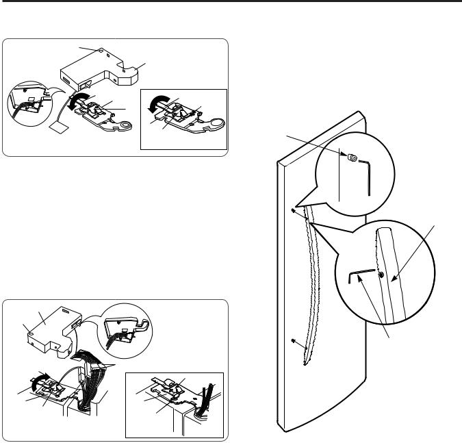
Removing the left (freezer) door with water line connection.
•Pull up the water feed tube while pressing area (Figure 1) as shown in the figure below.
•NOTE:If a tube end is deformed or abraded, trim the part away. Disconnecting the tube under the door causes about 0.5 liters water to flow out. Put a large container at end of tube to prevent water from draining onto the floor.
Figure 1 |
(2)
(1)
(4) |
(3) |
(5) |
|
|
(7) |
(5) |
|
(6) |
(6) |
|
Rivet |
(7) |
|
|
|
|
|
Type 1 |
|
Type 2 |
1.Open the door. Remove the top hinge cover screw (1).
2.Use a flat blade screwdriver to pry back the hooks (not shown) on the cabinet underside of the cover (2). Lift up the cover.
3.Disconnect all the wire harnesses (3).
4.Remove the grounding screw (4).
5.Rotate hinge lever (5) counterclockwise. Lift the top hinge (6) free of the hinge lever latch (7).
NOTE: Regardless the type of hinge lever (5); type1: without rivet or type 2: with rivet the removal process is the same.
 CAUTION: When lifting the hinge free of the latch, be careful that the door does not fall forward.
6.Lift the door from the lower hinge pin being careful to pull the water lines through the lower hinge pin.
7.Place the door, inside facing up, on a nonscratching surface.
- 10 -
Reinstalling the rigth (Refrigerator) door
(1)
|
(2) |
(3) |
(3) |
(4) |
|
(5) |
Rivet |
|
(4) |
|
(5) |
Type 1 |
Type 2 |
|
1.Place the door onto the lower hinge pin.
2.Fit top hinge (4) over hinge lever latch (5) into place. Rotate lever (3) counterclockwise to secure
hinge.
NOTE: Regardless the type of hinge lever (3); type1: without rivet or type 2: with rivet the removal process is the same.
3.Hook tab on switch side of corner under edge of wire opening in cabinet top. Position cover (2) into place. Insert and tighten cover screw (1).
Reinstalling the left (Freezer) door
(2) |
|
|
(1) |
|
|
(4) |
(3) |
|
(7) |
||
|
||
(5) |
(5) |
|
(6) |
(6) |
|
(7) |
Rivet |
|
|
||
Type 1 |
Type 2 |
1.Feed the water tubes through the lower hinge pin and place the door onto the lower hinge pin.
2.Fit top hinge (6) over hinge lever latch (7) and into place. Rotate lever (5) clockwise to secure hinge
NOTE: Regardless the type of hinge lever (5); type1: without rivet or type 2: with rivet the removal process is the same.
3.Install the grounding screw (4) and connect all the wire harnesses (3).
4.Hook tab on door switch side of cover (2) under edge of wire opening in cabinet top. Position cover into place. Insert and tighten cover screw (1).
5.Reconnect the water tubes by inserting the tubes into the connectors.
2.HANDLE REMOVAL
•Loosen the set screws with a 3/32” (2.38 mm) Allen wrench and remove the handle.
NOTE: If the handle mounting fasteners need to be tightened or moved, use a 1/4” (6.35 mm) Allen wrench.
Mounting fasteners
Set screw
Allen Wrench
- 11 -
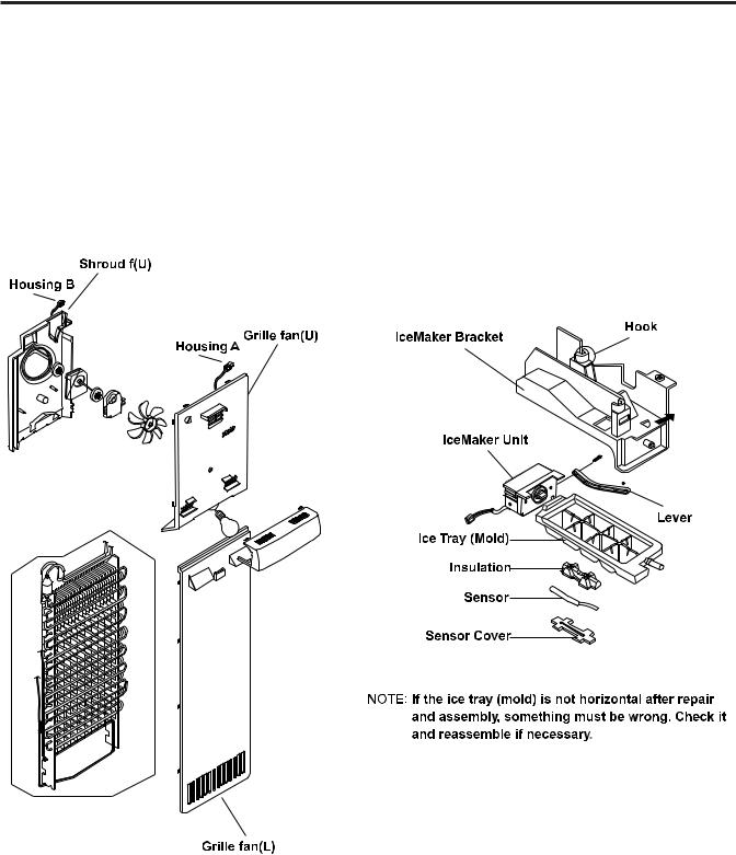
3. FAN SHROUD GRILLE |
4. ICEMAKER ASSEMBLY |
1.Loose one screw with a screwdriver blade.
2.Disassembly of an upper grille fan: Hold upper part of an upper grille fan (U) and pull forward carefully.
3.Disassembly of a lower grille fan: Hold upper part of a lower grille fan and pull forward carefully.
4.Disassembly of an upper freezer shroud: Hold lower part, oull forward and disconnect housing A and B.
5.Check foam sticking conditions around a shroud, upper freezer and lower freezer during assembling. If damaged torn, or badly stuck, assemble with a new one afer sealing well.
1. Dispenser Model
1)How to disassemble:
(1)Remove ice bin from the freezer compartment.
(2)Loose the screw on the upper part of icemaker bracket.
(3)Disconnect icemaker bracket so that it can slide forward.
(4)Disconnect icemaker housing and sensor housing.
(5)Disconnect icemaker horizontally by pressing bracket hook part. (Don’t disassemble further. The set value may be changed).
2)The assembly is the reverse order of the above disassembly.
- 12 -

5. WATER VALVE DISASSEMBLY
• Disassembly
1.Pull out tube while pressing collets and disassemble it.
•Assembly
1.Insert tube until you can see only one line. 
2. After inserting, pull out tube to check if it is properly inserted.
Collet
Tube
Insert Line
- 13 -
7. DISPENSER
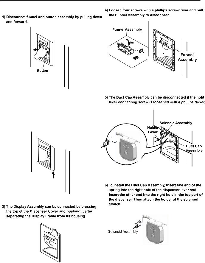
2) Remove the Display Frame moving out with both hands in one side and make the same process in the other side and pulling it forward like shows the picture.
- 14 -

5. MICOM FUNCTION
1. MONITOR PANEL
1-1. Display Second Function
|
2 |
1 |
Display Power Saving Mode |
1. Buzzer sound mute Mode
The buzzer sound is set to OFF.
It activates by sounding the recognition sound of “Ding ~” after pressing and holding ICE PLUS” button more than 5 seconds. It inactivates when resetting the mode power.
2. Display OFF mode.
Display off mode puts the display into standby mode until the door is opened.
To put the display into Display off Mode, press and hols the FRZ. TEMP. and ICE PLUS buttons simultaneously for 5 seconds until the Ding~sounds. (Use both buttons for this to work.) When Display off Mode is activated, the display remains OFF unless a door is opened or a button is pressed. The display will return to the OFF position after 30 seconds inactivity.
To remove the display from Display off Mode, press and hold the FREEZER and ICE PLUS buttons simultaneously for 5 seconds until the Ding~sounds. The Display off Mode default setting is OFF after a power interruption.
- 15 -

2. DESCRIPTION OF FUNCTION
2-1. FUNCTION OF TEMPERATURE SELECTION
Base
|
|
|
|
º |
º |
º |
º |
º |
|
||||||||
|
|
º |
º |
º |
º |
º |
||
|
||||||||
|
|
|
|
|
||||
º |
º |
|
|
|
||||
Press the button to cycle through the settings in this order: (Medium) |
(Medium High) (High) |
(Low) |
||||||
• |
|
|
|
|
||||
• |
|
|
|
|
||||
•
2-1-1 Lock Function (dispenser and display button lock)
1.In power application of refrigerator, the LOCK text is turned off at the right side of lock graphic of display with the lock release status.
2.If you wish lock the controls, push on the ALARM/LOCK button for more than 3 seconds, after this time, the LOCK graphic on the display will be turned on.
3.The buzzer sound and control panel and dispenser function is not performed even if pressing display button ather than lock key in the lock status.
4.If you wish unlock the controls, press the ALARM/LOCK button more than 3 seconds. The LOCK graphic on the display will be turned off.
- 16 -
2-1-2. Filter condition display function
1.There is a replacement indicator light for the water filter cartridge on the dispenser.
2.Water filter needs replacement once six months.
3.Water filter light and FILTER RESET HOLD 3 SECONDS text turn n to tell you need to replace the filter soon.
4.After replace the filter, press and hold the lock button more than 3 seconds.
Then water filter light and FILTER RESET HOLD 3 SECONDS text turn off with reset status.
 I
I


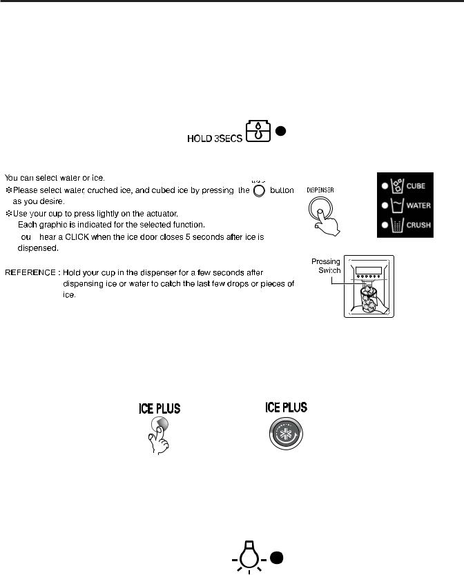
2-2. Dispenser use selection
•
• ´ll
´ll
2-3. ICE PLUS
Please select this function for prompt freezer.
• Function is repeated folloing below whenever pressing ICE PLUS
•The arrow mark graphic remains at the On status after flickering 4 times when selecting Special Refrigeration ICE PLUS.
• ICE PLUS function automatically turns off if a fixed time passes.
2-4 Dispenser Light
•Dispenser switch or dispenser light button turn the dispenser light in the dispenser on and off.
•The dispenser light Function is repeated following below whenever pressing LIGHT/FILTER button.
•If dispenser light continuously turns on more than 7 minutes with dispenser light button, the dispenser light turns off automatically by compulsion.
 I
I


- 17 -
2-5 ICE PLUS
1.Ice Plus increases the cooling speed in the freezer by running the fan and the compressor simultaneously.
2.Ice Plus is released if the power fails and is restored.
3.The temperature setting is not changed when Ice Plus is selected.
4.You can change the temperature in the freezer and the refrigerator even if Ice Plus has been selected and is in progress.
5.The refrigerator operates independently of the Ice Plus setting and operation.
6.At the end of the Ice Plus cycle, the freezer defaults to its original setting.
7.If frost removal starting time is arrived during Ice Plus, Ice Plus operation is done only for the remaining time after completion of frost removal when the Ice Plus operation time passes 90 minutes. If passing 90 minutes, Ice Plus operation is done only for 2 hours after completion of frost removal.
8.If pressing Ice Plus button during frost removal, the Ice Plus LCD or LED is turned on but if pressing the Ice Plus, compressor operates after the remaining time has passed.
9.If selection Ice Plus within 7 minutes (delay for 7 minutes of compressor) after the compressor stops, compressor operates after the remaining time has passed.
10.The freezer fan motor operates at the high speed of RPM during operation of Ice Plus.
2-6 Control of variable type of freezing fan
2-7 Control of cooling fan motor
- 18 -
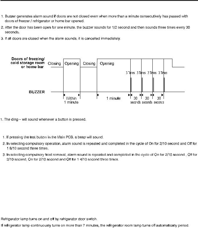
2-8. Door opening alarm
Closing
2-9. Ringing of button selection buzzer
2-10 Ringing of compulsory operation, compulsory frost removal buzzer
2-11 Defrost function
1.Defrost is performedwhenever total operation time of compressor becomes 7 - 50 hour.
2.In providing initial power (or returning power failure), frost removal starts whenever total operation time of compressor becomes 4 - 5 hours.
3.Defrost is completed if temperature of a defrost sensor becomes more than 5°C after starting defrost. The defrost cycle will fail if the refrigerator does not reach a temperature of 5°C (9°F) two hours into the defrost cycle.
4.The defrost cycle will not operate of the defrost sensor fails, arcs, or shorts cut.
2-12 Refrigerator lamp automatically off
- 19 -
2-13 Sequential operation of built-in product
Built-in products such as compressor, frost removal heater, freezing room fan, Cooling Fan and step motor damper are sequentially operated as follows for preventing noise and part damage occurred due to simultaneous operation of a lot of parts in applying initial power and completing test.
º C |
º |
º |
º |
- 20 -
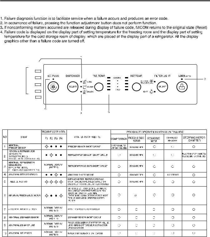
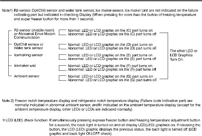
2-14. Failure Diagnosis Funtion
F4
F3
TROUBLE CODE INDEX F2
F1
- 21 -
- 22 -

2-15. Test Function
 ºC
ºC
- 23 -
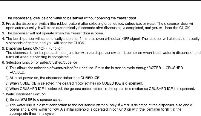
2.16. Function of dispenser and water dispenser built-in
- 24 -
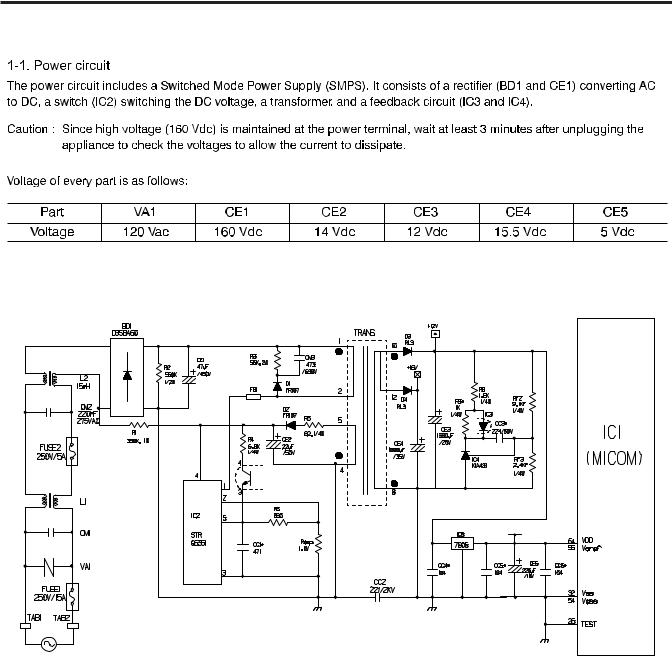
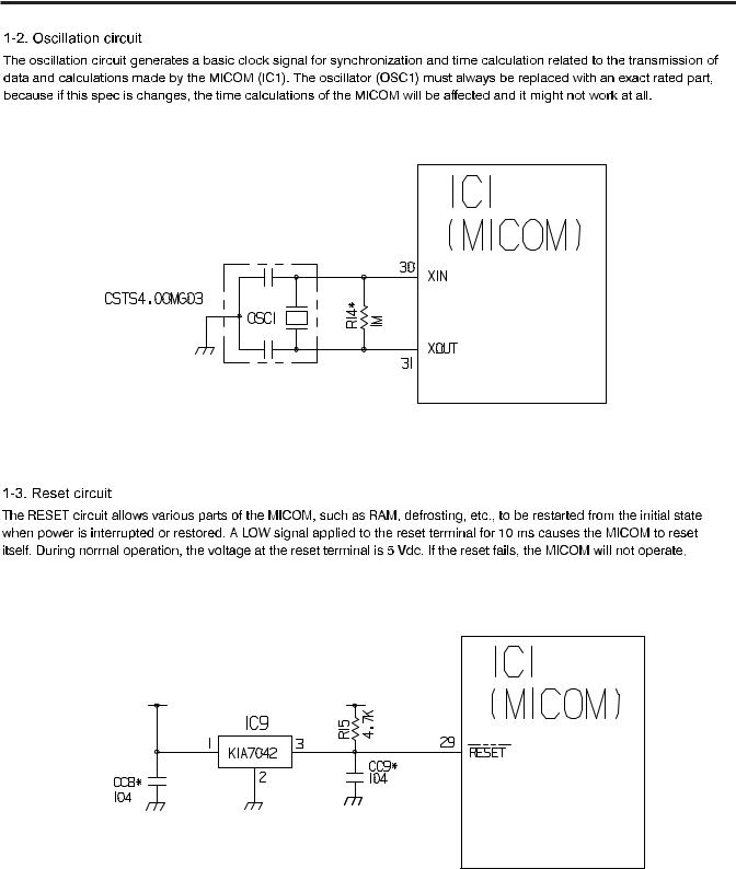
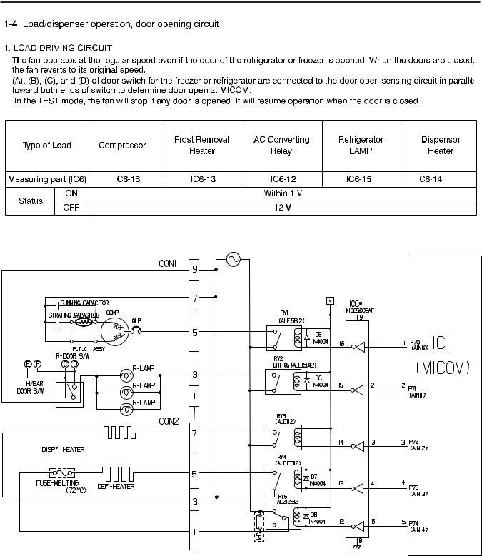
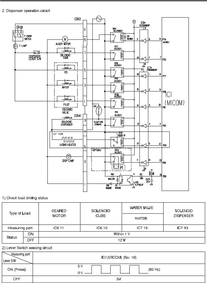
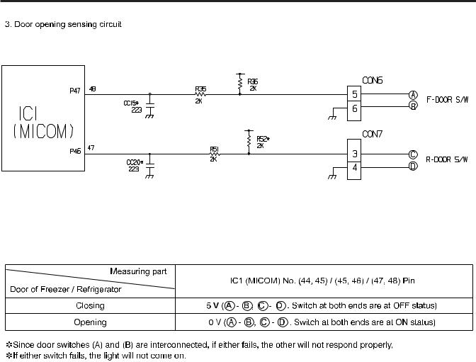
6. EXPLANATION FOR MICOM CIRCUIT
1. Explanation for PWB circuit
- 25 -
- 26 -
• |
• |
• |
- 27 -
- 28 -
- 29 -
 Loading...