


Internal Use Only
Website http://biz.lgservice.com
30” Freestanding Electric Range
SERVICE MANUAL
MODEL: LSB5682SW
LSB5682SB
LSB5682SS
CAUTION
BEFORE SERVICING THE UNIT, READ THE SAFETY PRECAUTIONS IN THIS MANUAL.
|
April, 2008 |
P/NO : MFL38379705 |
Printed in Korea |
|
|
|
|

FORWARD
This LG Service Manual, “30” Freestanding Self-Cleaning Electric Range,” provides the technician with information on the operation and service of the Freestanding Self-Cleaning
Electric Range. It is to be used as a training Service Manual. For specific information on the model being serviced, refer to the “Owner’s Manual” or “Tech Sheet” provided with the electric range.
SAFETY PRECAUTIONS
•Repairs of the appliance should be carried out by a licensed technician only. Incorrect repairs may result in dangerous situations. If you need repairs, contact an LG Service Center or your dealer.
•If the power cord is defective, it must be replaced by a qualified service agent with a UL listed range cord.
•Electrical leads and cables should not be allowed to touch the oven.
•Rating plate is located on the left side of warming drawer.
•The power supply of the appliance should be turned off when it is being repaired.
!WARNING
•DISCONNET power supply cord from the outlet before servicing.
•Replace all panels and parts before operating.
•RECONNECT all grounding devices.
- Failure to do so can result in severe personal injury, death or electrical shock.
• DO NOT Touch when the oven operates.
- The interior parts will be very hot.
LG Electronices assumes no responsibility for any repairs made
on our products by anyone other than Authorized Service Technicians.

TABLE OF CONTENTS
(PAGE)
GENERAL- - - - - - - - - - - - - - - - - - - - - - - - - - - - - - - - - - - - - - - - - - - - - - - - - - - - - - - - - - - - - - - - - - - - - - - - - - - - - - - - - - - - - - - - - - - - 1-1 ~ 1-4
• Important safety instructions - - - - - - - - - - - - - - - - - - - - - - - - - - - - - - - - - - - - - - - - - - - - - - - - - - - - - - - - - - - - - - - - - - - - - - - - - - - - - - - - - - - - - - |
1-1 ~ 1-2 |
• Model & Serial number label and tech sheet locations - - - - - - - - - - - - - - - - - - - - - - - - - - - - - - - - - - - - - - - - - - - - - - - - - - - - |
- - - - - - - 1-3 |
• Specifications - - - - - - - - - - - - - - - - - - - - - - - - - - - - - - - - - - - - - - - - - - - - - - - - - - - - - - - - - - - - - - - - - - - - - - - - - - - - - - - - - - - - - - - - - - - - - - - - - - - - - - - - - - - |
- - - - - - - 1-4 |
USING YOUR RANGE - - - - - - - - - - - - - - - - - - - - - - - - - - - - - - - - - - - - - - - - - - - - - - - - - - - - - - - - - - - - - - - - - - - - - - - - - 2-1 ~ 2-5
• General imformation - - - - - - - - - - - - - - - - - - - - - - - - - - - - - - - - - - - - - - - - - - - - - - - - - - - - - - - - - - - - - - - - - - - - - - - - - - - - - - - - - - - - - - - - - - - - - - - - - - |
- - - - - - - 2-1 |
• Control panel features - - - - - - - - - - - - - - - - - - - - - - - - - - - - - - - - - - - - - - - - - - - - - - - - - - - - - - - - - - - - - - - - - - - - - - - - - - - - - - - - - - - - - - - - - - - - - - |
2-2 ~ 2-5 |
-To turn on a single surface unit (Right Rear, Left Rear, Left Front)
-To turn on a dual surface unit (Right Front)
-To set the warming zone controlTo set the warming zone control
-Clock
-Start, Clean/Off and On/Off pad
-Oven light
-Timer On/Off
-Convection auto conversion
-Thermostat adjustment
-Preheating alarm light On/Off
-Beeper volume
-Temperature unit (°F or °C)
-Bake, Timed Bake, Delayed timed Bake
-Broil
-Convection Bake
-Convection Roast
-Cook & Warm
-Oven lockout
-Changing hour mode on clock (12HR, 24HR)
-Proof
-Self-Clean
-Warming drawer
COMPONENT ACCESS - - - - - - - - - - - - - - - - - - - - - - - - - - - - - - - - - - - - - - - - - - - - - - - - - - - - - - - - - - - - - - - - - - - - - 3-1 ~ 3-17
• Component Locations - - - - - - - - - - - - - - - - - - - - - - - - - - - - - - - - - - - - - - - - - - - - - - - - - - - - - - - - - - - - - - - - - - - - - - - - - - - - - - - - - - - - - - - - - - - |
- - - - - - - - - - - 3-1 |
• Removing the Back, Control cover and Key membrane Assembly - - - - - - - - - - - - - - - - - - - - - - - - - - - - - - - - - |
- - - - - - - - - - 3-2 |
• Removeing the Control Power Supply and Power Control Board (PCB) - - - - - - - - - - - - - - - - - - - - - - - - - |
- - - - - - - - - - 3-3 |
• Removing the Surface Element and the Ceramic Glass Cooktop - - - - - - - - - - - - - - - - - - - - - - - - - - - - - - - - - - |
- - - - - - - - - 3-4 |
• Removing the Door Latch and the Door Switch - - - - - - - - - - - - - - - - - - - - - - - - - - - - - - - - - - - - - - - - - - - - - - - - - - - - - - - - - - - |
- - - - - - - - - - 3-5 |
• Removing the BROIL element - - - - - - - - - - - - - - - - - - - - - - - - - - - - - - - - - - - - - - - - - - - - - - - - - - - - - - - - - - - - - - - - - - - - - - - - - - - - - - - - - |
- - - - - - - - - - 3-6 |
• Removing the BAKE element - - - - - - - - - - - - - - - - - - - - - - - - - - - - - - - - - - - - - - - - - - - - - - - - - - - - - - - - - - - - - - - - - - - - - - - - - - - - - - - - - - - |
- - - - - - - - - - 3-7 |
• Removing the CONVECTION Fan blade and Fan motor - - - - - - - - - - - - - - - - - - - - - - - - - - - - - - - - - - - - - - - - - - - - - - |
- - - - - - - - - - 3-8 |
• Removing the Oven light & Socket assembly - - - - - - - - - - - - - - - - - - - - - - - - - - - - - - - - - - - - - - - - - - - - - - - - - - - - - - - - - - - - - |
- - - - - - - - - - 3-9 |
• Removing the latch drive assembly - - - - - - - - - - - - - - - - - - - - - - - - - - - - - - - - - - - - - - - - - - - - - - - - - - - - - - - - - - - - - - - - - - - - - - - - - - - |
- - - - - - - - 3-10 |
- Door locking mechanism - - - - - - - - - - - - - - - - - - - - - - - - - - - - - - - - - - - - - - - - - - - - - - - - - - - - - - - - - - - - - - - - - - - - - - - - - - - - - - - - - - - - - - |
- - - - - - - - 3-10 |
• Removing the Oven temperature Sensor - - - - - - - - - - - - - - - - - - - - - - - - - - - - - - - - - - - - - - - - - - - - - - - - - - - - - - - - - - - - - - - - - - - |
- - - - - - - - 3-11 |
• Removing the storage drawer - - - - - - - - - - - - - - - - - - - - - - - - - - - - - - - - - - - - - - - - - - - - - - - - - - - - - - - - - - - - - - - - - - - - - - - - - - - - - - |
- - - - - - - - 3-12 |
• Removing & Replacing the Lift-off Oven Door - - - - - - - - - - - - - - - - - - - - - - - - - - - - - - - - - - - - - - - - - - - - - - - - - - - - - - - - - - - - - |
- - - - - - - - 3-13 |
• Removing the Oven Door Handle & Glass - - - - - - - - - - - - - - - - - - - - - - - - - - - - - - - - - - - - - - - - - - - - - - - - - - - - - - - - - - - - - - - - |
3-14 ~ 3-15 |
• Removing the Oven Door Gasket - - - - - - - - - - - - - - - - - - - - - - - - - - - - - - - - - - - - - - - - - - - - - - - - - - - - - - - - - - - - - - - - - - - - - - - - - - - - - |
- - - - - - - - 3-16 |
• Removing a Side Panel - - - - - - - - - - - - - - - - - - - - - - - - - - - - - - - - - - - - - - - - - - - - - - - - - - - - - - - - - - - - - - - - - - - - - - - - - - - - - - - - - - - - - - - - - - - |
- - - - - - - - 3-17 |

(Page)
COMPONENT TEST - - - - - - - - - - - - - - - - - - - - - - - - - - - - - - - - - - - - - - - - - - - - - - - - - - - - - - - - - - - - - - - - - - - - - - - - - - - - - 4-1 ~ 4-7
• Convection Motor - - - - - - - - - - - - - - - - - - - - - - - - - - - - - - - - - - - - - - - - - - - - - - - - - - - - - - - - - - - - - - - - - - - - - - - - - - - - - - - - - - - - - - - - - - - - - - - - - - - - - - - - - - - |
4-1 |
• Door locking Motor - - - - - - - - - - - - - - - - - - - - - - - - - - - - - - - - - - - - - - - - - - - - - - - - - - - - - - - - - - - - - - - - - - - - - - - - - - - - - - - - - - - - - - - - - - - - - - - - - - - - - - - - - |
4-2 |
• Micro Switch (normally open type) - - - - - - - - - - - - - - - - - - - - - - - - - - - - - - - - - - - - - - - - - - - - - - - - - - - - - - - - - - - - - - - - - - - - - - - - - - - - - - - - - - - |
4-2 |
• LVT - - - - - - - - - - - - - - - - - - - - - - - - - - - - - - - - - - - - - - - - - - - - - - - - - - - - - - - - - - - - - - - - - - - - - - - - - - - - - - - - - - - - - - - - - - - - - - - - - - - - - - - - - - - - - - - - - - - - - - - - - - - - - - - |
4-2 |
• Oven Sensor - - - - - - - - - - - - - - - - - - - - - - - - - - - - - - - - - - - - - - - - - - - - - - - - - - - - - - - - - - - - - - - - - - - - - - - - - - - - - - - - - - - - - - - - - - - - - - - - - - - - - - - - - - - - - - - - - |
4-3 |
• Door switch - - - - - - - - - - - - - - - - - - - - - - - - - - - - - - - - - - - - - - - - - - - - - - - - - - - - - - - - - - - - - - - - - - - - - - - - - - - - - - - - - - - - - - - - - - - - - - - - - - - - - - - - - - - - - - - - - - - |
4-3 |
• Broil element - - - - - - - - - - - - - - - - - - - - - - - - - - - - - - - - - - - - - - - - - - - - - - - - - - - - - - - - - - - - - - - - - - - - - - - - - - - - - - - - - - - - - - - - - - - - - - - - - - - - - - - - - - - - - - - - - |
4-3 |
• Bake element - - - - - - - - - - - - - - - - - - - - - - - - - - - - - - - - - - - - - - - - - - - - - - - - - - - - - - - - - - - - - - - - - - - - - - - - - - - - - - - - - - - - - - - - - - - - - - - - - - - - - - - - - - - - - - - - |
4-3 |
• Oven lamp - - - - - - - - - - - - - - - - - - - - - - - - - - - - - - - - - - - - - - - - - - - - - - - - - - - - - - - - - - - - - - - - - - - - - - - - - - - - - - - - - - - - - - - - - - - - - - - - - - - - - - - - - - - - - - - - - - - - |
4-4 |
• Single surface unit(RF, LR, RR) - - - - - - - - - - - - - - - - - - - - - - - - - - - - - - - - - - - - - - - - - - - - - - - - - - - - - - - - - - - - - - - - - - - - - - - - - - - - - - - - - - - - - - |
4-5 |
• Warming Zone(CR) - - - - - - - - - - - - - - - - - - - - - - - - - - - - - - - - - - - - - - - - - - - - - - - - - - - - - - - - - - - - - - - - - - - - - - - - - - - - - - - - - - - - - - - - - - - - - - - - - - - - - - - |
4-6 |
• Dual surface unit(LF) - - - - - - - - - - - - - - - - - - - - - - - - - - - - - - - - - - - - - - - - - - - - - - - - - - - - - - - - - - - - - - - - - - - - - - - - - - - - - - - - - - - - - - - - - - - - - - - - - - - - - - |
4-7 |
COMPOSITION OF CONTROL - - - - - - - - - - - - - - - - - - - - - - - - - - - - - - - - - - - - - - - - - - - - - - - - - - - - - - - - - - - - - |
5-1 ~ 5-4 |
• Main PCB - - - - - - - - - - - - - - - - - - - - - - - - - - - - - - - - - - - - - - - - - - - - - - - - - - - - - - - - - - - - - - - - - - - - - - - - - - - - - - - - - - - - - - - - - - - - - - - - - - - - - - - - - - - - |
- - - - - - - - - - - 5-2 |
• Cook-top display PCB - - - - - - - - - - - - - - - - - - - - - - - - - - - - - - - - - - - - - - - - - - - - - - - - - - - - - - - - - - - - - - - - - - - - - - - - - - - - - - - - - - - - - - - - - - - - |
- - - - - - - - - - 5-3 |
• Oven relay PCB - - - - - - - - - - - - - - - - - - - - - - - - - - - - - - - - - - - - - - - - - - - - - - - - - - - - - - - - - - - - - - - - - - - - - - - - - - - - - - - - - - - - - - - - - - - - - - - - - - - - - |
- - - - - - - - - - 5-3 |
FAILURE MODE FLOW CHART - - - - - - - - - - - - - - - - - - - - - - - - - - - - - - - - - - - - - - - - - - - - - - - - - - - - - - - - - - - - |
6-1 ~ 6-11 |
• No display (No power) - - - - - - - - - - - - - - - - - - - - - - - - - - - - - - - - - - - - - - - - - - - - - - - - - - - - - - - - - - - - - - - - - - - - - - - - - - - - - - - - - - - - - - - - |
- - - - 6-1 ~ 6-4 |
• Oven does not heat - - - - - - - - - - - - - - - - - - - - - - - - - - - - - - - - - - - - - - - - - - - - - - - - - - - - - - - - - - - - - - - - - - - - - - - - - - - - - - - - - - - - - - - - - - - - |
- - - 6-5 ~ 6-7 |
• Cook-top does not heat - - - - - - - - - - - - - - - - - - - - - - - - - - - - - - - - - - - - - - - - - - - - - - - - - - - - - - - - - - - - - - - - - - - - - - - - - - - - - - - - - - - - - - - |
- - - 6-8 ~ 6-9 |
• Oven lamp does not operate - - - - - - - - - - - - - - - - - - - - - - - - - - - - - - - - - - - - - - - - - - - - - - - - - - - - - - - - - - - - - - - - - - - - - - - - - - - - - - - |
- - - - - - - - - - 6-10 |
• No key input - - - - - - - - - - - - - - - - - - - - - - - - - - - - - - - - - - - - - - - - - - - - - - - - - - - - - - - - - - - - - - - - - - - - - - - - - - - - - - - - - - - - - - - - - - - - - - - - - - - - - - |
- - - - - - - - - - 6-11 |
FAILURE CODES- - - - - - - - - - - - - - - - - - - - - - - - - - - - - - - - - - - - - - - - - - - - - - - - - - - - - - - - - - - - - - - - - - - - - - - - - - - - - - - - - |
- - - - - - - - - 7-0 |
F-CODE FLOW CHART - - - - - - - - - - - - - - - - - - - - - - - - - - - - - - - - - - - - - - - - - - - - - - - - - - - - - - - - - - - - - - - - - - - - - |
7-1 ~ 7-10 |
• F-1 error - - - - - - - - - - - - - - - - - - - - - - - - - - - - - - - - - - - - - - - - - - - - - - - - - - - - - - - - - - - - - - - - - - - - - - - - - - - - - - - - - - - - - - - - - - - - - - - - - - - - - - - - - - - - - |
- - - - - - - - - - - 7-1 |
• F-2 error - - - - - - - - - - - - - - - - - - - - - - - - - - - - - - - - - - - - - - - - - - - - - - - - - - - - - - - - - - - - - - - - - - - - - - - - - - - - - - - - - - - - - - - - - - - - - - - - - - - - - - - - - - - - |
- - - 7-2 ~ 7-4 |
• F-3, F-4 error - - - - - - - - - - - - - - - - - - - - - - - - - - - - - - - - - - - - - - - - - - - - - - - - - - - - - - - - - - - - - - - - - - - - - - - - - - - - - - - - - - - - - - - - - - - - - - - - - - - - - - |
- - - 7-5 ~ 7-6 |
• F-9 error - - - - - - - - - - - - - - - - - - - - - - - - - - - - - - - - - - - - - - - - - - - - - - - - - - - - - - - - - - - - - - - - - - - - - - - - - - - - - - - - - - - - - - - - - - - - - - - - - - - - - - - - - - - - |
- 7-9 ~ 7-10 |
TROUBLE SHOOTING - - - - - - - - - - - - - - - - - - - - - - - - - - - - - - - - - - - - - - - - - - - - - - - - - - - - - - - - - - - - - - - - - - - - - - - - - 8-1 ~ 8-3
SCHEMATIC DIAGRAM - - - - - - - - - - - - - - - - - - - - - - - - - - - - - - - - - - - - - - - - - - - - - - - - - - - - - - - - - - - - - - - - - - - - - - - - - - - - - - - - - - 9-1
• STRIP CIRCUITS - - - - - - - - - - - - - - - - - - - - - - - - - - - - - - - - - - - - - - - - - - - - - - - - - - - - - - - - - - - - - - - - - - - - - - - - - - - - - - - - - - - - - - - - - - - - - - - - - - - - 9-2 ~ 9-5
EXPLODED VIEW - - - - - - - - - - - - - - - - - - - - - - - - - - - - - - - - - - - - - - - - - - - - - - - - - - - - - - - - - - - - - - - - - - - - - - - - - - - - 10-1 ~ 10-9 REPLACEMENT PARTS LIST - - - - - - - - - - - - - - - - - - - - - - - - - - - - - - - - - - - - - - - - - - - - - - - - - - - - - - - - - - - 11-1 ~ 11-9

GENERAL
IMPORTANT SAFETY INSTRUCTIONS
Read and follow all instructions before using your oven to prevent the risk of fire, electric shock, injury to person, or damage when using the range. This guide don’t cover all possible conditions that may occur. For further assistance contact your service agent or manufacturer.
This is the safety alert symbol. This symbol alerts you to potential hazards that can kill or hunt you
!and others. All safety messages will follow the safety alert symbol and either the word “WARNING” or “CAUTION”. These word means :
!WARNING
!CAUTION
This symbol will alert you to hazards or unsafe practices which could cause serious bodily harm or death.
This symbol will alert you to hazards or unsafe practices which could cause bodily injury or property damage.
!WARNING
•DO NOT step or sit on the door and install the Anti-Tip Bracket packed with range.
-The range could be tipped and injury might result from spilled hot liquid, food, or the range itself.
-If the range is pulled away from the wall for cleaning, service, or any other reason, ensure that the Anti-Tip Device is properly reengaged when the range is pushed back against the wall.
•DISCONNET power supply cord from the outlet before servicing.
•Replace all panels and parts before operating.
•RECONNECT all grounding devices.
- Failure to do so can result in severe personal injury, death or electrical shock.
• DO NOT touch heating elements or interior surfaces of oven.
-Heating element may be hot even though they are dark in color.
-Interior surfaces of an oven become hot enough to cause burns.
•During and after use, do not touch, or let clothing or other flammable materials contact heating elements or interior surfaces of oven until they have had sufficient
time to cool.
-Other surfaces of the appliance may become hot enough to cause burns among these surfaces are oven vent openings and surfaces near these openings, oven doors, and windows of oven doors.
•DO NOT store items of interest to children in cabinets above a range or on the back guard of a range.
- Children climbing on the range to reach items could be seriously injured.
!CAUTION
•Always use Pot Holders or oven mitts when removing food from the Warming Drawer.
- You can be burned as cookware and plates will be hot.
• Be careful when you work on the electric range handling the sheet metal part.
- Sharp edge may be present and you can cut yourself.
• Be careful not to bend the fan blade
- Failure to do so can result in vibration, noise, and poor performance of convection when operating.
•Be careful not to scratch or chip the oven liner paint when you remove the oven light socket in the next step.
•Turn power OFF before removing the Warming Drawer.
•Be careful when removing and lifting the door.
•DO NOT lift the door by the handle.
- Failure to do so can result in personal injury as the door is very heavy.
1-1
GENERAL
IMPORTANT SAFETY INSTRUCTIONS
•Be sure your appliance is properly installed and grounded by a qualified technician.
•Do not repair or replace any part of the appliance unless specifically recommended in the manual.
All other servicing should be referred to a qualified technician.
•Always disconnect power to appliance before servicing by removing the fuse or switching off the circuit breaker
!WARNING
• DO NOT step or sit on the door and install the Anti-Tip Bracket packed with range.
- The range could be tipped and injury might result from spilled hot liquid, food, or the range itself.
-If the range is pulled away from the wall for cleaning, service, or any other reason, ensure that the Anti-Tip Device is properly reengaged when the range is pushed back against the wall.
To reduce the risk of tipping of the range, the range must be secured by properly installed anti-tip devices. To check if the bracket is installed properly,
-Warming drawer : grasp the top rear edge of the Range and carefully attempt to tilt it forward.
verify that the anti-tip devices are engaged.
-Storage drawer : Remove drawer and verify leveling leg is inserted into and fully secured by the anti-tip devices.
Refer to the installation manual for proper anti-tip bracket installation.
!WARNING
•DO NOT touch heating elements or interior surfaces of oven.
-Heating element may be hot even though they are dark in color.
-Interior surfaces of an oven become hot enough to cause burns.
•During and after use, do not touch, or let clothing or other flammable materials contact heating elements or interior surfaces of oven until they have had sufficient time to cool.
-Other surfaces of the appliance may become hot enough to cause burns among these surfaces are oven vent openings and surfaces near these openings, oven doors, and windows of oven doors.
!WARNING
•DO NOT store items of interest to children in cabinets above a range or on the back guard of a range.
-Children climbing on the range to reach items could be seriously injured.
1-2

GENERAL
IMPORTANT SAFETY INSTRUCTIONS
•Do Not Leave Children Alone - Children should not be left alone or unattended in area where appliance is in use. They should never be allowed to sit or stand on any part of the appliance.
•Never Use Your Appliance for Warming or Heating the Room.
•Storage in or on Appliance – Flammable materials should not be stored in an oven or near surface units. Be sure all packing materials are removed from the appliance before operating it. Keep plastics, clothes and paper away from parts of the appliance that may become hot
•Wear Proper Apparel – Loose-fitting or hanging garments should never be worn while using the appliance.
•Do Not Use Water on Grease Fires – Turn off oven to avoid spreading the flame. Smother the fire or flame by closing the door or use dry chemical, baking soda or foamtype extinguisher.
•Use Only Dry Potholders – Moist or damp potholders on hot surfaces may result in burns from steam.
Do not let potholder touch hot heating elements. Do not use a towel or other bulky cloth.
!WARNING
•DISCONNET power supply cord from the outlet before servicing.
•Replace all panels and parts before operating.
•RECONNECT all grounding devices.
-Failure to do so can result in severe personal injury, death or electrical shock.
SURFACE COOKING UNITS
•Use Proper Pan Size – This appliance is equipped with one or more surface units of different sizes. Select utensils having flat bottoms large enough to cover the surface unit heating element. The use of undersized utensils will expose a portion of the heating element to direct contact and may result in ignition of clothing. Proper relationship of utensil to burner will also improve efficiency.
•Never Leave Surface Units Unattended at High Heat Settings – Boil overs may cause smoking and greasy spillovers may ignite.
•Make Sure Reflector Pans or Drip Bowls Are in Place – Absence of these pans or bowls during cooking may subject wiring or components underneath to damage.
•Protective Liners – Do not use aluminum foil to line surface unit drip bowls or oven bottoms, except as suggested in the manual. Improper installation of these liners may result in a risk of electric shock, or fire.
•Glazed Cooking Utensils – Only certain types of glass, glass/ceramic, ceramic, earthenware, or other glazed utensils are suitable for rangetop service without breaking due to the sudden change in temperature.
•Utensil Handles Should Be Turned Inward and Not Extend Over Adjacent Surface Units – To reduce the risk of burns, ignition of flammable materials, and spillage due to unintentional contact with the utensil, the handle of a utensil should be positioned so that it is turned inward, and does not extend over adjacent surface units.
•Do Not Soak Removable Heating Elements – Heating elements should never be immersed in water.
•Be sure you know which control pads operate each surface unit. Make sure you turned on the correct surface unit.
SELF-CLEAN OVENS
•Do Not Clean Door Gasket – The door gasket is essential for a good seal. Care should be taken not to rub, damage, or move the gasket.
•Do Not Use Oven Cleaners – No commercial oven cleaner or oven liner protective coating of any kind should be used in or around any part of the oven.
•Clean in the self-clean cycle only parts listed in this manual.
Before self-cleaning the oven, remove the broiler pan and any utensils from the oven.
•Never keep pet birds in the kitchen – the health of birds is extremely sensitive to the fumes released during an oven selfclean cycle. Fumes may be harmful or fatal to birds. Move birds to well-ventilated room.
•Important Instruction – In the event the self-clean mode “F” code goes on, or three long beeps sound, oven is malfunctioning in the self-clean mode. Turn off or disconnect appliance from power supply and have serviced by a qualified technician.
VENTILATING HOODS:
•Clean Ventilating Hoods Frequently – Grease should not be allowed to accumulate on hood or filter.
•When flaming foods under the hood, turn the fan on.
OVEN
•Use Care When Opening Door – Let hot air or steam escape before you remove or replace food in the oven
•Do Not Heat Unopened Food Containers – Build-up of pressure may cause container to burst and result in injury.
•Keep Oven Vent Ducts Unobstructed – the oven vent is located above the left rear surface unit. this area could become hot during oven use. Never block this vent and never place plastic or heatsensitive items on vent
•Placement of Oven Racks – Always place oven racks in desired location while oven is cool. If rack must be moved while oven is hot, do not let potholder contact hot heating element in oven.
•Do Not allow aluminum foil or meat probe to contact heating elements.
GLASS/CERAMIC COOKING SURFACES
•Do Not Cook on Broken Cook-Top – If cook-top should break, cleaning solutions and spillovers may penetrate the broken cooktop and create a risk of electric shock. Contact a qualified technician immediately.
•Clean Cook-Top With Caution – If a wet sponge or cloth is used to wipe spills on a hot cooking area, be careful to avoid steam burn. Some cleaners can produce noxious fumes if applied to a hot surface.
DEEP FAT FRYERS:
•Use extreme caution when moving the grease kettle or disposing of hot grease.
1-3
GENERAL
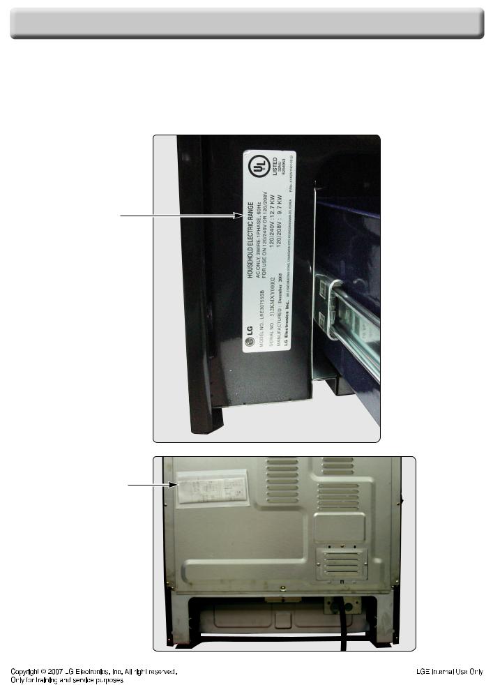
MODEL & SERIAL NUMBER LABEL AND TECH SHEET LOCATIONS
The Model/Serial Number label and
Model & Serial
Number Location
Tech Sheet Location
(On Low Rear Cover)
1-4

|
|
|
|
|
GENERAL |
||||||||
|
|
|
|
SPECIFICATIONS |
|||||||||
|
|
|
|
|
|
|
|
|
|
|
|
|
|
|
|
|
|
Model Number |
LSB5682SW / LSB5682SB / LSB5682SS |
||||||||
|
|
|
|
|
|
|
|
|
|
|
|
|
|
|
|
|
|
Category |
Convection |
||||||||
Overall |
|
Width |
30" |
|
|
|
|
|
|
|
|
||
|
|
|
|
Installation type |
Freestanding |
||||||||
|
|
|
|
Color availability |
WH, BK, STS |
||||||||
Control |
|
Oven |
Keypad |
||||||||||
|
|
|
|
Cooktop |
Keypad |
||||||||
|
|
|
|
Display |
LED |
||||||||
|
|
|
|
Electronic clock & timer |
Yes |
||||||||
|
|
|
|
Control lock capability |
Yes |
||||||||
|
|
|
|
Audible preheat signal |
Yes |
||||||||
|
|
|
|
Special function |
|
|
|
|
|
|
|
|
|
|
|
|
|
|
1. Clock(12hr, 24hr) |
||||||||
|
|
|
|
|
2. Temperature unit (F / C) |
||||||||
|
|
|
|
|
3. Beeper Volume(High , Low, Mute) |
||||||||
|
|
|
|
|
4. Smart oven light On/Off |
||||||||
|
|
|
|
|
5. Convection auto conversion on/off |
||||||||
|
|
|
|
|
6. Thermostat Adjustment |
||||||||
|
|
|
|
|
7. Sabbath mode |
||||||||
|
|
|
|
|
|
|
|
|
|
|
|
|
|
Cooktop |
|
Material |
Ceramic glass |
||||||||||
|
|
|
|
# of element |
5 |
|
|
|
|
|
|
|
|
Power |
|
LR |
6"-1,200 |
|
|
|
|
|
|
|
|
||
|
|
|
|
RR |
6"-1,200 |
|
|
|
|
|
|
|
|
|
|
|
|
CR |
warming zone |
||||||||
|
|
|
|
LF |
9"-2,500 |
|
|
|
|
|
|
|
|
|
|
|
|
RF |
Dual (9”/12"-1,700/2,700) |
||||||||
Oven |
|
Capacity(cu.ft) |
5.6 |
|
|
|
|
|
|
|
|
||
|
|
|
|
Broil element |
4000 watt |
||||||||
|
|
|
|
Bake element |
3400 watt |
||||||||
|
|
|
|
Convection System |
Yes |
||||||||
|
|
|
|
-Convection element |
No |
||||||||
|
|
|
|
# of Racks |
2 standards |
||||||||
|
|
|
|
Interior oven light |
120 V, 40Watt |
||||||||
|
|
|
|
Proof |
Yes |
||||||||
|
|
|
|
Cook & warm |
Yes |
||||||||
|
|
|
|
Favorites |
No |
||||||||
|
|
|
|
|
|||||||||
|
|
|
|
|
|
|
|
|
|
|
|
|
|
|
|
|
|
Door lockout |
Yes |
||||||||
|
|
|
|
Broiler pan |
Yes |
||||||||
Drawer |
|
Type |
Storage drawer |
||||||||||
|
|
|
|
Element |
- |
|
|
|
|
|
|
|
|
|
|
|
|
Warming rack |
- |
|
|
|
|
|
|
|
|
Dimensions |
|
Oven Interior(W x H x D) |
24 1/2 x 20 1/4 x 19 3/8 |
||||||||||
(inch) |
|
Exterior - Width |
29 7/8 |
|
|
|
|
|
|
|
|
||
|
|
|
|
Exterior - Height |
36 (cooktop), 47 5/8 (backguard top) |
||||||||
|
|
|
|
Exterior - Depth |
25 11/16 (Door), 28 (with handle) |
||||||||
|
|
|
|
Net weight: Lbs (Kg) |
181 lbs (82kg) |
||||||||
Power |
|
Rating |
48A(120/240 V) / 42A(120/208 V) |
||||||||||
|
|
|
|
|
1-5 |
|
|
|
|
|
|
|
|
|
|
|
|
|
|
|
|
|
|||||
|
|
|
|
|
|
|
|
|
|||||
USING YOUR RANGE
GENERAL INFORMATION
Rating Label
Model numbers are recorded on the rating label. Rating label is located on the lower front left corner of the oven frame. It can be seen by opening the storage drawer or warming drawer. Before ordering parts, write down the correct model and serial number from rating label. This avoids incorrect shipments and delays. Please refer to parts reference material when ordering replacement parts.
Functional Operation
Bake Mode
Top and hidden bottom elements operate during bake. Bake can be used to cook foods which are normally baked. Oven must be preheated.
 Broil element
Hidden bake element
Convection Bake / Roast Mode
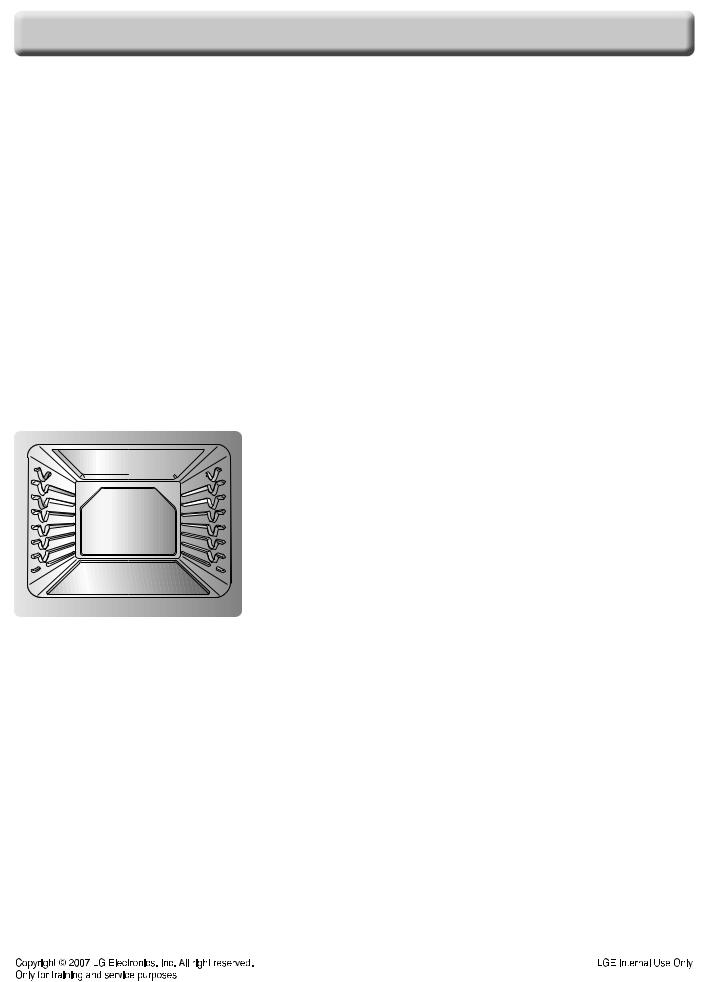
Upper element, lower element, Rear element(some model) and fan operate during convection bake. Convection bake should be used for cooking casseroles and roasting meats. Oven should be preheated for best results when using convection bake. Pans do not need to be staggered. Cooks approximately 25% quicker than bake.
Broil element
Convection element
Hidden bake element
Cooking Guide
Refer to the owners manual for recommendations of times and temperatures. Times, rack position, and temperatures may vary depending on conditions and food type. For best results, always check food at minimum time. When roasting, choose rack position based on size of food item.
Broil Mode
Top element operates during broil. Broil can be used to cook foods which are normally broiled. Preheating is not required when using broil. All foods should be turned at least once except fish, which does not need to be turned.
 Broil element
Hidden bake element
2-1
USING YOUR RANGE
CONTROL PANEL FEATURES
A single |
C |
A single |
||||
|
|
|
Warming zone |
|
|
|
Left Rear element |
Right Rear element |
|||||
16 |
1 |
3 |
4 |
2 |
5 |
|
6 |
||
|
|
|
|
|
|
|
|
|
|
|
|
|
|
|
|
|
|
|
|
|
|
|
|
|
|
|
|
|
|
|
|
|
|
|
|
|
|
|
|
|
|
|
|
|
|
|
|
|
|
|
|
|
|
|
|
|
|
|
|
|
|
|
|
|
|
|
|
|
|
|
|
|
|
|
|
|
|
|
|
|
|
|
|
|
|
|
|
|
|
8 |
9 |
10 |
11 |
12 |
13 |
14 |
15 |
7 |
A single |
B Dual |
||||
|
|
|
|
|
|
Left Front element |
Right Front |
||||
|
|
|
Dual element |
||
1.BAKE PAD: Press to select the bake function.
2.BROIL PAD: Press to select the broil function.
3.CONVECTION BAKE PAD: Press to select baking with the convection function.
4.CONVECTION ROAST PAD: Press to select roasting with the convection function.
5.NUMBER PADS: Use to set any function requiring numbers such as the time of day on the clock, the timer, the oven temperature, the start time and length of operation for timed baking.
6.START PAD: Must be pressed to start any cooking or cleaning function.
12.COOK & WARM PAD: Press to keep cooked foods warm. See the how to set the oven for warming section.
13.PROOF PAD: Press to select a warm environment useful for rising yeast-leavened products.
14.SELF CLEAN PAD: Press to select self-cleaning function. See the using the Self-Cleaning Oven section.
15.OVEN LIGHT PAD: Press to turn the oven light on or off.
16.DISPLAY
7.CLEAR/OFF PAD: Press to cancel all oven operations except the clock and timer.
8.CLOCK PAD: Press before setting the time of day.
9.TIMER ON/OFF PAD: Press to select the timer feature.
10.COOK TIME PAD: Press and then use the number pads to set the amount of time you want your food to cook. The oven will shut off when the cooking time has run out.
11.START TIME PAD: Use along with BAKE, CONV. BAKE, CONV. ROAST, COOK TIME and SELF CLEAN pads to set the oven to start and stop automatically at a time you set.
2-2
ASingle surface units
: Right Rear, Left Rear, Left Front
BDual surface unit : Right Front
CWarming Zone : Center Rear

USING YOUR RANGE
A To turn on a single surface unit (Right Rear, Left Rear, Left Front)
Press ON/OFF pad for the desired element. Press (  /
/  ) pad to choose the desired setting.
B To turn on a dual surface unit (Right Front)
Press ON/OFF pad
Press the ELEMENT SIZE pad as needed to select the desired burner size. Default size is 9”. When first selected, 12” size is ON. The light above the ELEMENT SIZE pad indicates which size surface unit is on.
Press (  /
/  ) pad to choose the desired setting.
time a pad is pressed a beep will sound. power level decreases or increases by 0.5
9.0 through 3.0. (by 0.2 from 3.0 through 1.0) is the lowest power level available.
will appear when the unit is hot to touch
C To set the warming zone control
1.Press ON/OFF pad at the warming zone.
2.Press (  /
/  ) pad to choose the desired setting.
Note:
•Each time a pad is pressed a beep will sound.
•The controls for the warming zone allow for 5 different heat settings : Lo~Hi
•“HS” will appear when the unit is hot to touch.
1. SETTING THE CLOCK
CLEAR |
|
|
CLOCK |
|
|
Desired |
|
|
START |
/OFF |
|
|
|
|
Clock |
|
|
||
|
|
|
|
|
|
|
|
||
|
|
|
|
|
|
|
|
|
|
2.START, CLEAN/OFF AND ON/OFF PAD
1.Touch START pad to start oven.
2.Touch CLEAR/OFF pad to cancel a program during cooking or Erase during programming.
3.Touch ON/OFF pad to start or cancel the surface unit.
3.TO TURN ON/OFF THE OVEN LIGHT
The oven light automatically turns ON when the Door is opened. The oven light may also be Manually turned ON or OFF by pressing the
OVEN LIGHT pad
Note: The oven light cannot be turned on if self-clean feature is active.
4. TIMER ON/OFF |
|
|
|
|
|||
|
|
|
|
|
|
|
|
|
TIMER |
|
|
Desired |
|
|
TIMER |
|
ON/OFF |
|
|
time |
|
|
ON/OFF |
|
|
|
|
|
|
|
|
To cancel timer at any time, touch TIMER ON/OFF pad.
Note:
1.If you press TIMER ON/OFF pad once, it allows you to make a “second” unit of timer setting.
(for example: if you press “5” and “6”, it means 56 seconds)
2.If you press TIMER ON/OFF pad twice, it allows you to make a “minute” unit of timer setting.
(for example: if you press “5” and “6”, it means 56 minutes)
5.CHANGING HOUR MODE ON CLOCK (12HR, 24HR)
Press and hold the COOK&WARM pad for 3 seconds
Press “1” pad once for 12-hour,
START
“1” pad twice for 24-hour.
6.TEMPERATURE UNIT (°F or °C)
1.Press and hold COOK&WARM pad for 3 seconds
2.Press “2” pad once for °F
or “2” pad twice for °C
3.Press START pad’
7.BEEPER VOLUME
1.Press and hold COOK&WARM pad for 3 seconds
2.Press “3” pad once for “Beep Hi” Press “3” pad to switch beeper volume
(HI, LO, OFF)
3.Press START pad
8.PREHEATING ALARM LIGHT ON/OFF
1.Press and hold COOK&WARM pad for 3 seconds
2.Press “4” pad once for ON
or “4” pad twice for OFF
3.Press START pad
9.CONVECTION AUTO CONVERSION
1.Press and hold COOK&WARM pad for 3 seconds
2.Press “5” pad once for ON
or “5” pad twice for OFF 3. Press START pad.
2-3

USING YOUR RANGE
10.THERMOSTAT ADJUSTMENT
The oven temperature can be adjusted from -35°F (-19°C) to 35°F (19°C).
Note: The thermostat adjustments made with this feature will just change Bake, Convection Bake and Convection Roast temperature.
To increase the oven temperature:
1.Press and hold BAKE pad for 3 seconds
2.Press the desired temperature
3.Press START pad.
To decrease the oven temperature:
1.Press and hold BAKE pad for 3 seconds
2.Press the desired temperature
3.Press the BAKE pad once
4.Press START pad
11.SABBATH MODE
1.Set the BAKE (or Timed BAKE, Delay Timed Bake)
2.Press START pad
3.Press and hold the BROIL pad for 3 seconds
4.Press START pad
To Cancel SABBATH mode
1.Press and hold “BROIL” pad for 3 seconds
2.Press START pad.
Note: You may change the oven temperature once baking has started.Press BAKE, enter the oven temperature change (170 to 550F °) and press START (For Jewish Holidays only). Remember that the oven control will no longer beep or display any further changes once the oven is set for the Sabbath feature.
12. BAKE, TIMED BAKE, DELAYED TIMED BAKE
Desired
BAKE START temperature
COOK
Desired time START
TIME
START |
|
|
Desired |
|
|
START |
TIME |
|
|
start time |
|
|
|
|
|
|
|
|
||
|
|
|
|
|
|
|
13. BROIL
BROIL: once |
Hi |
|
START |
|
: twice |
Low |
|
|
|
|
|
|||
|
|
|
|
|
14. CONVECTION BAKE
CONV. |
|
|
Desired |
|
|
START |
BAKE |
|
|
Temp. |
|
|
|
|
|
|
|
|
||
|
|
|
|
|
|
|
15. CONVECTION ROAST
CONV. |
|
|
Desired |
|
|
START |
ROAST |
|
|
Temp. |
|
|
|
|
|
|
|
|
||
|
|
|
|
|
|
|
16. COOK & WARM
COOK & |
|
START |
|
WARM |
|
|
|
|
|
||
|
|
|
|
17. OVEN LOCKOUT
Press and hold the START pad for 3 seconds (to activate or reactivate LOCKOUT)
18. PROOF
PROOF  START
START
19. SELF-CLEAN
|
|
SELF CLEAN |
|
|
START |
|||||||
|
|
: Once |
3-hour |
|
|
|
||||||
|
|
|
|
|
||||||||
|
|
: Twice |
2-hour |
|
|
|
||||||
|
|
: 3 times |
4-hour |
|
|
|
||||||
|
|
|
|
|
|
|
|
|
|
|
|
|
|
|
|
|
|
|
|
|
|
|
|
||
|
|
|
|
|
|
|
|
|
||||
|
|
|
START |
|
|
Desired |
|
START |
||||
|
|
|
TIME |
|
|
start time |
|
|
||||
|
|
|
|
|
|
|
||||||
|
|
|
|
|
|
|
|
|
|
|
|
|
2-4
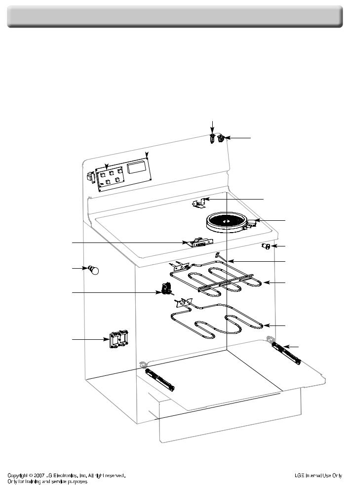
COMPONENT ACCESS
This section instructs you on how to service each component inside the range. The components and their locations are shown below.
COMPONENT LOCATIONS
Cook Top |
Main PCB |
||
Display PCB |
|
|
|
|
|
|
|
|
|
|
|
|
|
|
|
LVT 
Door Latch Assembly
Oven Light
Convection Motor
Oven Relay PCB
Circuit Breaker
Appliance Outlet
Door Locking Motor
& Micro Switch
Surface Elements
Door Switch
Oven Sensor
Broil Heater
Bake Heater
Hinge Hanger
3-1
COMPONENT ACCESS
REMOVING THE BACK, CONTROL COVER AND KEY MEMBRANE ASSEMBLY
!WARNING
•DISCONNET power supply cord from the outlet before servicing.
•Replace all panels and parts before operating.
•RECONNECT all grounding devices.
-Failure to do so can result in severe personal injury, death or electrical shock.
!CAUTION
•Be careful when you work on the electric range handling the sheet metal part.
-Sharp edge may be present and you can cut yourself.
going to the range. wall so that you can
the rear panel and
 Control Cover
4.Remove the 3 screws from the rear control cover and remove the cover.
5.Remove 6 screws of PCB assembly and separate PCB assembly.
6.Remove 9 screws of KEY Membrane assembly and separate PCB assembly.
PCB Assembly
KEY MEMBRANE Assembly
 Back Cover
3-2

COMPONENT ACCESS
REMOVING THE CONTROL POWER SUPPLY AND POWER CONTROL BOARD (PCB)
!WARNING
•DISCONNET power supply cord from the outlet before servicing.
•Replace all panels and parts before operating.
•RECONNECT all grounding devices.
-Failure to do so can result in severe personal injury, death or electrical shock.
!CAUTION
•Be careful when you work on the electric range handling the sheet metal part.
-Sharp edge may be present and you can cut yourself.
1.Turn off the electrical supply going to the range.
2.Pull the range away from the wall so that you can access the rear panel.
3.Remove back cover & control cover (See step 3~4 on page 3-2)
4.There are 3 PCB's (power control board). When you check PCB, check the proper pcb in default mode and check main pcb.
NOTE: Refer to the page 5-1~5-3 for composition of control board
Main PCB
Oven
Relay PCB
5. |
supply: |
2 Connector
2 Screws
3-3
COMPONENT ACCESS
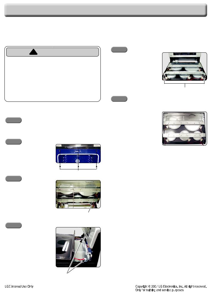
REMOVING THE SURFACE ELEMENTS AND THE CERAMIC GLASS COOKTOP
!WARNING
•DISCONNET power supply cord from the outlet before servicing.
•Replace all panels and parts before operating.
•RECONNECT all grounding devices.
-Failure to do so can result in severe personal injury, death or electrical shock.
Step. 5
Protect the cooktop surface and turn the assembly over.
Bracket screws
Step. 6
To remove the surface
CERAMIC GLASS COOKTOP
Step. 1
Unplug the cord or disconnect
Step. 2
Open oven door and remove the 3screws at the front of the cookthen close the door.
Step. 3
Lift up the cooktop front and Remove the ground screw securing ground wire
a)Remove the wires from the element and limiter terminals.
b)Remove the element bracket screw (shown above) for the element you are servicing.
d)Carefully lift the bottom of the bracket just far enough to remove the element.
REASSEMBLY NOTE: When you reinstall the element make sure that the wires are inserted into the correct tap then reinstall the bracket screw to secure it to the
Ground Screws
Step. 4
Slightly lift up and pull up the cook-top and then unplug the 2 connectors at the back by squeezing side tabs
2 Connectors
3-4

COMPONENT ACCESS
REMOVING THE DOOR LATCH & DOOR SWITCH
b) Remove the door latch from the burner box and unhook the actuating rod.
!WARNING
•DISCONNET power supply cord from the outlet before servicing.
•Replace all panels and parts before operating.
•RECONNECT all grounding devices.
-Failure to do so can result in severe personal injury, death or electrical shock.
!CAUTION
Unhook
Actuating
Rod
5. To remove the |
switch: |
a) If not already |
raise the cooktop |
(see page 3 |
the procedure). |
•Be careful when you work on the electric range handling the sheet
metal part.
-Sharp edge may be present and you can cut yourself.
1.Turn off the electrical supply going to the range.
2.Open the oven door.
3.Raise the cooktop (see page 3-4 for the procedure).
4.To remove the door latch:
a)Remove the two screws from the door latch and remove the latch.
b) Remove the |
|
|
switch from the range. |
|||
To do this, squeeze tabs and use a ratchet |
||||||
extension or |
small socket, and tap it out of |
|||||
the hole with |
hammer. |
|||||
|
|
|
|
|
|
|
|
|
|
|
|
|
|
|
|
|
|
|
|
|
|
|
|
|
|
|
|
|
|
|
|
|
|
|
|
Wires |
2 Screws |
Door |
|
Switch |
3-5

COMPONENT ACCESS
REMOVING THE BROIL ELEMENT
!WARNING
•DISCONNET power supply cord from the outlet before servicing.
•Replace all panels and parts before operating.
•RECONNECT all grounding devices.
-Failure to do so can result in severe personal injury, death or electrical shock.
!CAUTION
•Be careful when you work on the electric range handling the sheet metal part.
-Sharp edge may be present and you can cut yourself.
1.Turn off the electrical supply going to the range.
2.Open the oven door and remove the racks from inside the oven.
3.To remove the broil element:
a)Remove the 4 screws from the front and rear brackets.
b)Pull the element forward so that you can access the terminals and disconnect the wires.
2 Terminals
2 Upper bracket Screws
2 Rear bracket Screws
3-6

COMPONENT ACCESS
REMOVING THE HIDDEN BAKE ELEMENT
1. Unplug range or disconnect power. |
7. Bend the insulation glass fiber up. |
2.Pull the range out of its mounting location so that you can access the rear of the unit.
3.Remove the rear panel from the unit. (See step 3 on page 3-2 for procedure)
Hidden bake element
8. Remove two screws |
Screw |
and bend up two flanges |
|
Flanges
4.Remove the 2 screws of power cord assembly box and 1 ground screw.
5.Set the box aside
9.Carefully pull the hidden bake element and its mounting bracket out of the range.
6.Cut the 9 points of flange and remove the bake heater cover.
REPLACING THE MOUNTING BRACKET
Total 9 points
1. Drive the two screws
3-7
COMPONENT ACCESS
REMOVING THE CONVECTION ELEMENT, FAN BLADE AND FAN MOTOR
1.Disconnect power and remove oven racks.
2.Pull the range out of its mounting location so that you can access the rear of the unit.
3.Remove the rear panel from the unit. (See step 3~4 on page 3-2 for procedure)
4.Disconnect the wire connection.
7.To remove Fan motor assembly, disconnect wire connection and remove the three bracket screws
8.Pull the fan motor assembly forward.
5.Remove the four Fan cover screws and set the fan cover aside.
Fan |
|
Fan motor |
|
blade |
Support |
||
|
|||
Fan cover |
|
Washer |
|
|
|
||
|
|
Mounting |
|
Fan cover |
|
Screws |
|
|
(3ea) |
||
Screws |
|
|
|
(4ea) |
Cavity |
||
|
|||
|
Inner |
Outer |
|
Nut
6. To remove Fan blade, remove Nut by screwing clockwise. Fan blade can
|be replaced from inside oven.
Nut
!CAUTION
•Be careful not to bend the fan blade
-Failure to do so can result in vibration, noise, and poor performance of convection when operating.
3-8
COMPONENT ACCESS
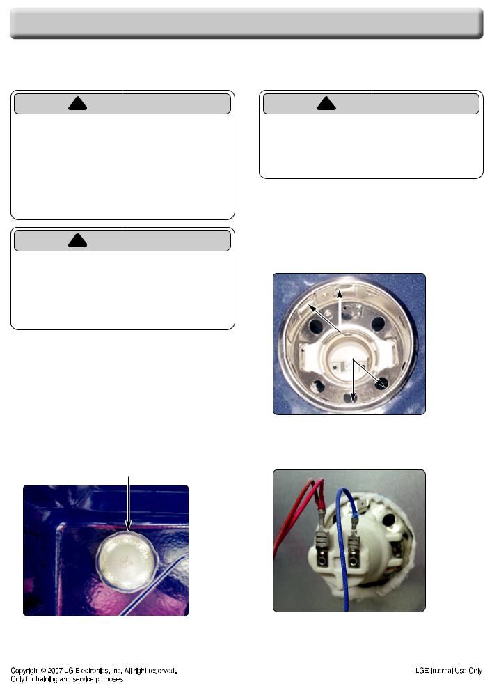
REMOVING THE OVEN LIGHT & SOCKET ASSEMBLY
! WARNING |
! CAUTION |
•DISCONNET power supply cord from the outlet before servicing.
•Replace all panels and parts before operating.
•RECONNECT all grounding devices.
-Failure to do so can result in severe personal injury, death or electrical shock.
!CAUTION
•Be careful when you work on the electric range handling the sheet metal part.
-Sharp edge may be present and you can cut yourself.
To replace:
1.Unplug range or disconnect power.
2.Turn the glass bulb cover in the back of the oven counterclockwise to remove.
3.Turn bulb counterclockwise to remove from socket.
4.Replace bulb and bulb cover by turning clockwise.
Glass cover & Bulb
•Be careful not to scratch or chip the oven liner paint when you remove the oven light socket in the next step.
5.Use a screwdriver and bend the clips on the oven light socket away from the edges of the liner hole, and pull the socket out of the liner.
NOTE: If it is too difficult to remove the socket from the front of the oven, you will have to push the socket out from the back of the unit.
Socket Clips
5. Disconnect the wires from the socket terminals.
<Viewed From Rear Panel>
3-9

COMPONENT ACCESS
REMOVING THE LATCH DRIVE ASSEMBLY
! WARNING
DOOR LOCKING MECHANISM
•DISCONNET power supply cord from the outlet before servicing.
•Replace all panels and parts before operating.
•RECONNECT all grounding devices.
-Failure to do so can result in severe personal injury, death or electrical shock.
!CAUTION
•Be careful when you work on the electric range handling the sheet metal part.
-Sharp edge may be present and you can cut yourself.
1.Turn off the electrical supply going to the range.
2.Pull the range away from the wall so that you can access the rear panel.
3.Remove the back cover & control cover (see step 3~4 on page 3-2).
4.Disconnect the wires from the latch drive motor and switch.
5.Remove the two mounting screws from the latch drive.
screws |
screws |
The door lock assembly is located at the back side of range.
The structural elements are as below.
1.When the oven control is programmed and started for the Self clean and Lock out mode, PCB (Power control board) chip operates the motor.
HOOK
Latch ROD
|
|
|
|
CAM |
|
|
|
|
|
|
|
|
|
MICRO |
|
|
|
|
|
|
|
|
|
SWITCH |
|
|
|
|
MOTOR |
|
|
|
|
|
2. |
|
|
to latch rod |
|
|
|
|
(from locked |
|
3.The cam activates the micro switch that causes the motor to stop.
4.The locked status remains until the range temperature drops to approximately 500F after end of the self clean or lock out feature is reactivated. The motor operates to unlock door at that time.
6. Unhook the Latch rod from the cam.
3-10
 Loading...